the Creative Commons Attribution 4.0 License.
the Creative Commons Attribution 4.0 License.
 | 18 Jan 2021
Design and analysis of a novel deployable hexagonal prism module for parabolic cylinder antenna
Xiaofei Ma
Yang Li
Tuanjie Li
Hangjia Dong
Dawei Wang
Juntao Zhu
This paper presents a novel deployable hexagonal prism module for parabolic cylinder antennas that exhibit characteristics of geometric scalability. The hexagonal prism module consists of six basic rib mechanisms distributed along the axis and parabolic directions of the parabolic cylinder. The basic rib mechanism along the axis direction is designed, and the position of each member in the deployed state is calculated according to the geometric relationships at the folded state. The basic rib mechanism along the parabolic direction is designed to ensure that the mechanism can be fully folded. The degree of freedom of basic loop mechanisms consisting of four basic rib mechanisms due to the splice of multiple modules is analyzed. The degree of freedom of the proposed hexagonal prism module is verified through simulations and experiments of a deployable mechanism composed of three hexagonal prism modules. The simulation and experiment results show that the proposed hexagonal prism module can offer synchronized and coordinated movement during the deployment process.
- Article
(5885 KB) - Full-text XML
- BibTeX
- EndNote


Space-deployable antennas have many successful applications, including space stations, satellite communications, and deep-space explorations. Due to the limitation of space and the carrying capacity of the carrier, deployable antennas are required to be light and have a high storage ratio. Deployable truss antennas have the characteristics of high storage ratio and good structural stability, which have attracted the interest of many researchers.
The parabolic cylinder deployable truss antenna has the advantages of strong directivity, easy beam scanning, and high gain. It has been widely applied to search radar, radio telescopes, and so on. In 2011, the Air Force Research Laboratory studied a parabolic cylindrical antenna called a large-scale, phased-array-fed reflector (Lane et al., 2011). In 2015, the National Astronomical Observatory of the Chinese Academy of Sciences designed a 45 m × 40 m antenna array for the Xinjiang Tianlai project to detect dark energy in the universe (Chen et al., 2016). The designed antenna array is composed of three feed-forward parabolic cylindrical antennas, and its receiving area is 15 m × 40 m. NASA has designed and tested a dual-band (Ka/W) aperture antenna that uses an offset parabolic cylinder as the main reflector. This antenna was installed on NASA's ER-2 aircraft for W-band high-altitude suborbital radar measurements (Spence et al., 2016). At present, the main types of parabolic cylinder deployable mechanisms include foldable plates (Yu et al., 2014), driving mechanisms by an inflatable hardening tube (Im et al., 2007), scissor mechanisms (Brancart et al., 2016; Zhang et al., 2020), and Bennett mechanisms (Xiao et al., 2019; Song et al., 2017). Yu et al. (2014) proposed a parabolic cylindrical deployable structure composed of foldable plates, which is deployed by releasing lateral and longitudinal constraints. Im and Durden (2007) introduced a prototype model of a parabolic cylinder antenna. It was made of a film supported by a linkage mechanism and deployed by an inflatable hardening tube. The above two mechanisms deployed by the deformation of members, which causes poor controllability. Brancart et al. (2016) designed a parabolic cylinder structure which has a deployable grid and a restraining membrane. So, it has the advantages of stable geometry and structural characteristics. Zhang et al. (2020) introduced a parabolic cylindrical antenna with a hinged rib mechanism for which the structural form is similar to the umbrella. Each module of the antenna is divided into the transverse mechanism and longitudinal mechanism. Xiao et al. (2019) proposed a parabolic cylinder mechanism composed of Bennett linkage connected by scissor units. This mechanism adjusts the pulling force direction of the driving cable through a pulley that is deployed. Song et al. (2017) put forward a parabolic cylinder mechanism based on Bennett linkage and studied the deployment performance. However, the joint structure among modules is weak, and bearing capacity is low. They are not suitable for large-scale antennas. The deployable truss reflector is composed of some basic modules, which can be connected into a large-scale deployable structure by changing the size and number of modules (Liu et al., 2012). Lin et al. (2019) developed a modular parabolic cylinder deployable mechanism with 1 degree of freedom. Dong et al. (2019) proposed a truss parabolic cylinder deployable antenna which uses the parallelogram mechanism as a basic deployable unit. But, the parallelogram mechanism cannot make the antenna fold fully.
This paper proposes a novel deployable hexagonal prism module for parabolic cylindrical antennas. Based on the geometric property of the module connection, basic rib mechanisms along the axis and parabolic directions of the hexagonal prism module are designed to ensure that the mechanism can be folded fully. Finally, the degree of freedom and kinematic characteristics are investigated for the deployable mechanism spliced by multiple hexagonal prism modules. Simulation and experimental analysis are conducted for a deployable mechanism composed by three designed hexagonal prism modules.
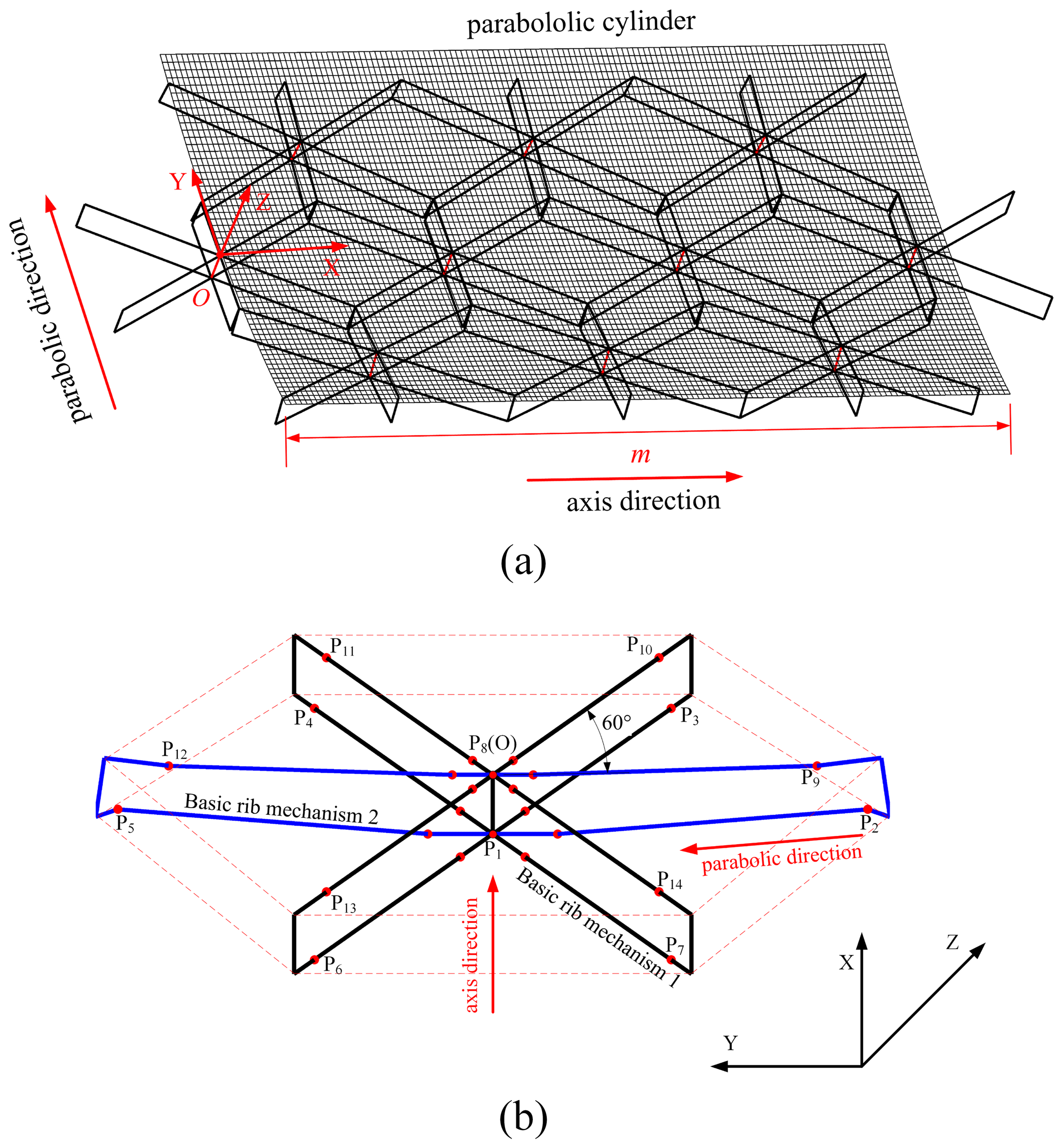
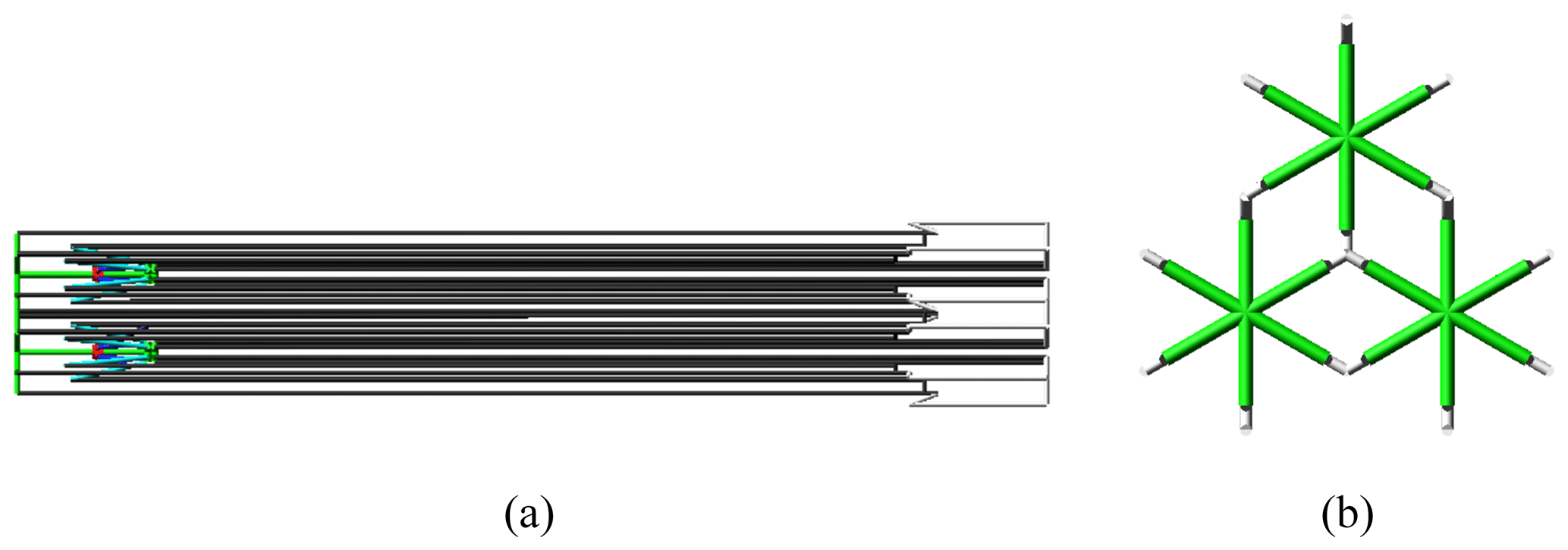
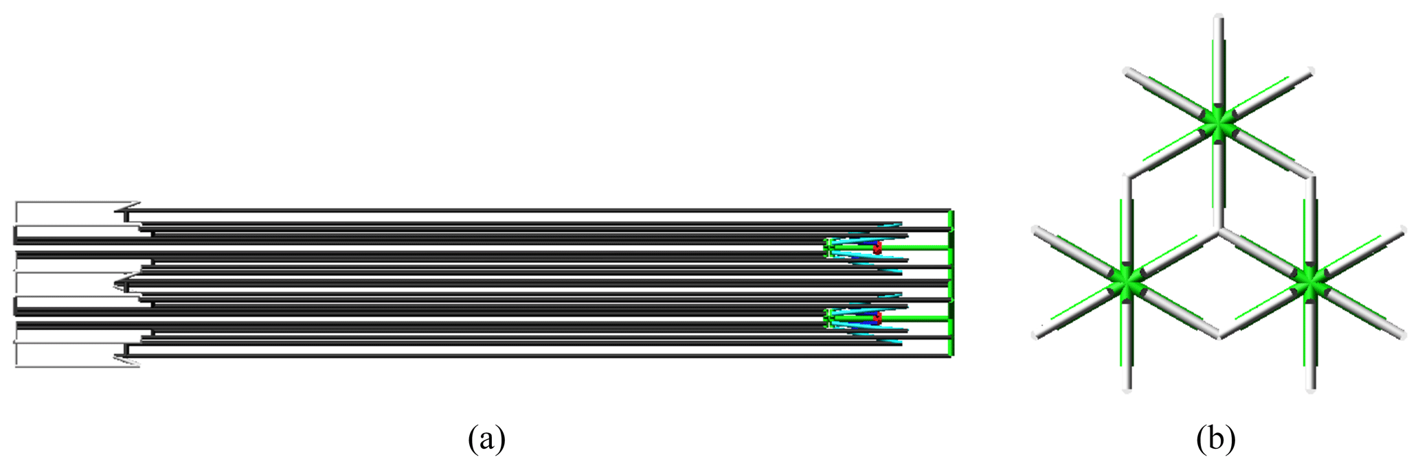
Figure 1Composition of parabolic cylinder antenna. (a) Deployable mechanism of antenna. (b) Hexagonal prism module.
2.1 Compositions of parabolic cylinder antenna
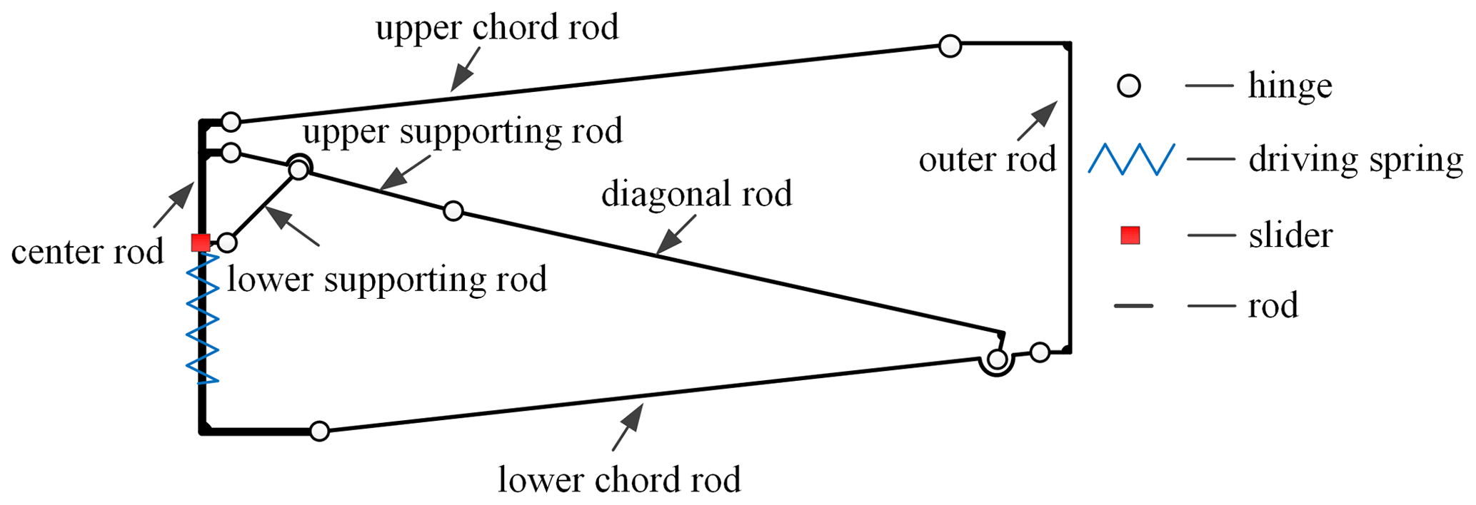
The deployable mechanism of a parabolic cylinder antenna is formed by splicing multiple hexagonal prism modules along the axis and parabolic direction, and its storage ratio is about 12.7, as shown in Fig. 1a. The hexagonal prism module in Fig. 1b is composed of four basic rib mechanism 1, labeled with black solid lines, and two basic rib mechanism 2, labeled with blue solid lines. The basic rib mechanism 2 is along the parabolic direction, and the angle between the basic rib mechanism 1 and the axis direction is 30∘. The projected angle between two adjacent basic rib mechanisms is 60∘. In each hexagonal prism module, six basic rib mechanisms share a center rod equipped with a driving spring and a slider, which can control the folding and unfolding of six basic rib mechanisms simultaneously. Each basic rib mechanism is constructed with a center rod, a driving spring, a slider, an upper supporting rod, a lower supporting rod, a diagonal rod, an upper chord, a lower chord, and an outer rod, as shown in Fig. 2. The basic rib mechanism 1 is a parallelogram mechanism, and the basic rib mechanism 2 is an ordinary planar four-bar mechanism.
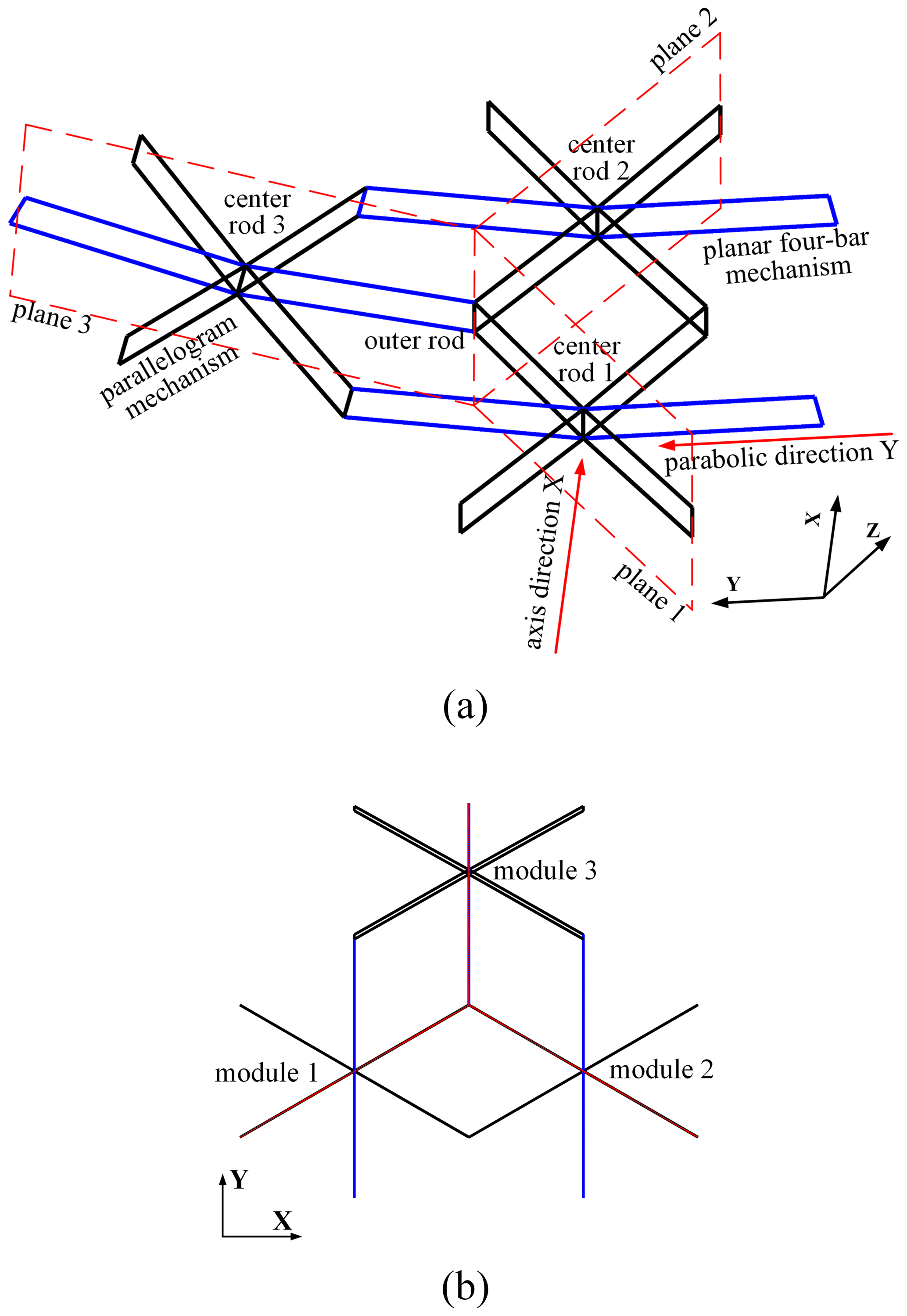
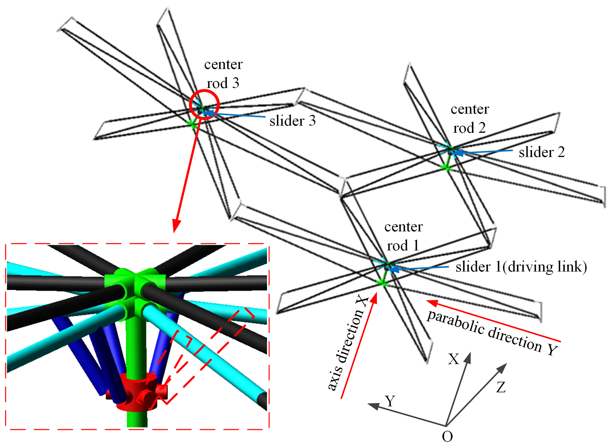
We will take a deployable mechanism consisting of three hexagonal prism modules, shown in Fig. 3, to illustrate the design procedure. In the figure, planes 1, 2, and 3, in which the three basic rib mechanisms are located, are orthogonal. The orthogonal line coincides with the outer rod when three modules are connected. In the completely unfolded state, the straight lines of center rods 1 and 2 along the axis direction are parallel to the outer rod, while the center rod 3 is not parallel to the outer rod. In order to ensure that the connected modules can be folded completely, the center rods of all modules are parallel to the outer rod in the folded state. Thus, some design requirements must be considered for the hexagonal prism module. In Fig. 3, four basic rib mechanisms, namely rib mechanism 1, are used as parallelogram mechanisms, and two basic rib mechanism 1 are planar four-link mechanisms. The reason is that the planar four-link mechanism can change the rotation angle between the outer rod and center rod during the deployment process, but the parallelogram mechanism does not have this function.
All nodes on the upper surface of hexagonal prism module, shown in Fig. 1b as P8 ∼ P14, are on the working surface of the fitting cylinder. According to the fitting cylinder equation, the coordinates of these nodes on the upper surface are able to be obtained. The fitting cylinder equation is derived by the least squares method, and we then obtain the radius R (in this paper R = 17 m) and center coordinates of the fitting circle. If the total lengths of the parabolic cylinder and the coordinate origin are m and O, respectively, as shown in Fig. 1a, the coordinates of the node P10 on the outer rod of the parallelogram mechanism is as follows:
where , , , N is the maximum number of modules along the axis direction, and N=4 in this paper.
The heights of the center rod and outer rod are h, and the distances from nodes P10 and P9 to the circle center are L1. The coordinates of node P9 on the outer rod are obtained. And if the straight line of the center rod is along the radius direction of the cylindrical surface, then the coordinates of node P2 on the outer rod are the following:
where α1 is the central angle of chord length L1, and α2 is the central angle of the projection of line OP10 onto the y axis.
2.2 Mechanism design
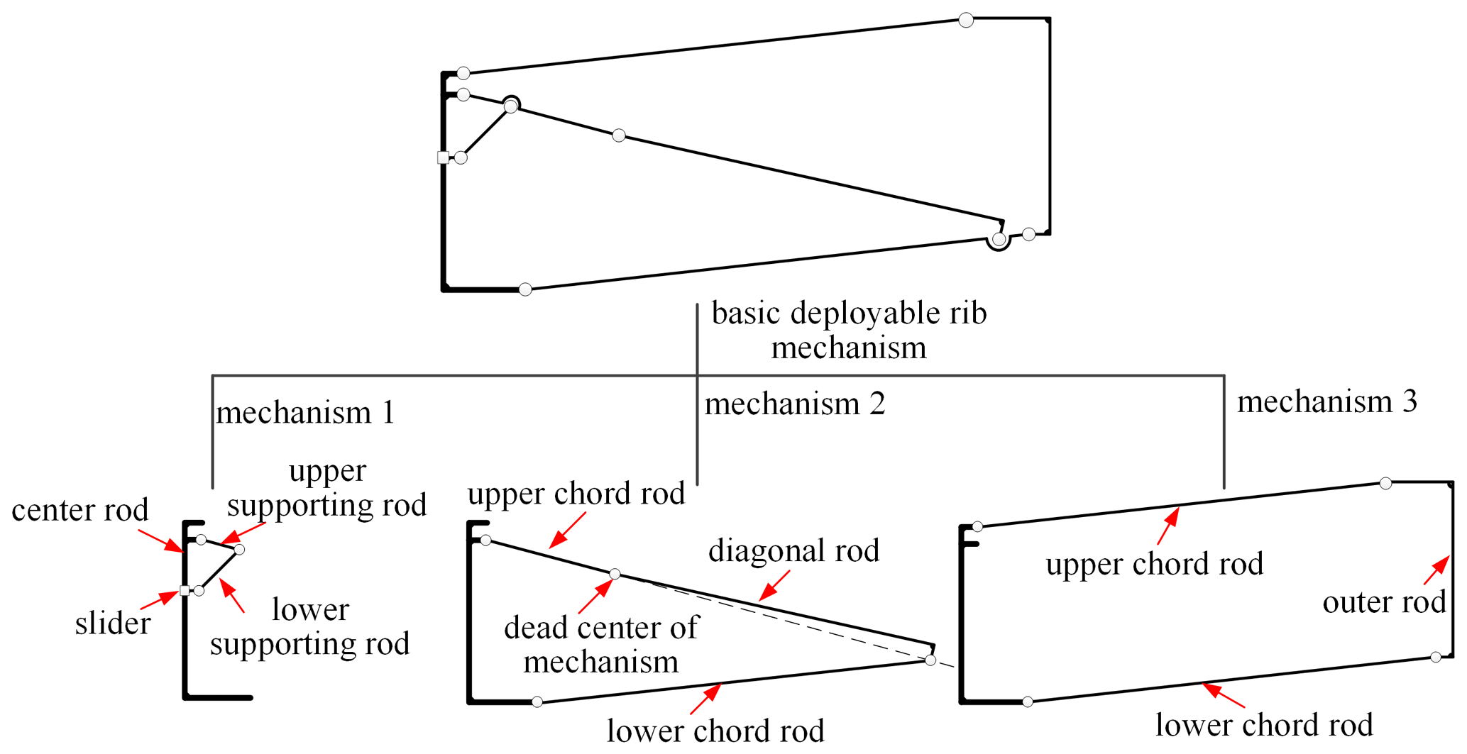
The key of the design of the parabolic cylinder antenna is the reasonable design of the basic rib mechanism. The selected basic rib mechanism is a multi-loop linkage mechanism. In order to facilitate analysis, we split the basic rib mechanism into three single loop mechanisms, as shown in Fig. 4.
In mechanism 2, if the driving link was the lower chord (rocker) rather than the slider, the position of the dead point between the upper supporting rod and the diagonal rod would appear as shown in Fig. 4. When the mechanism 2 is at the dead point position, we regard the basic deployable rib mechanism as being in fully deployed state, and the slider reaches its limit position.
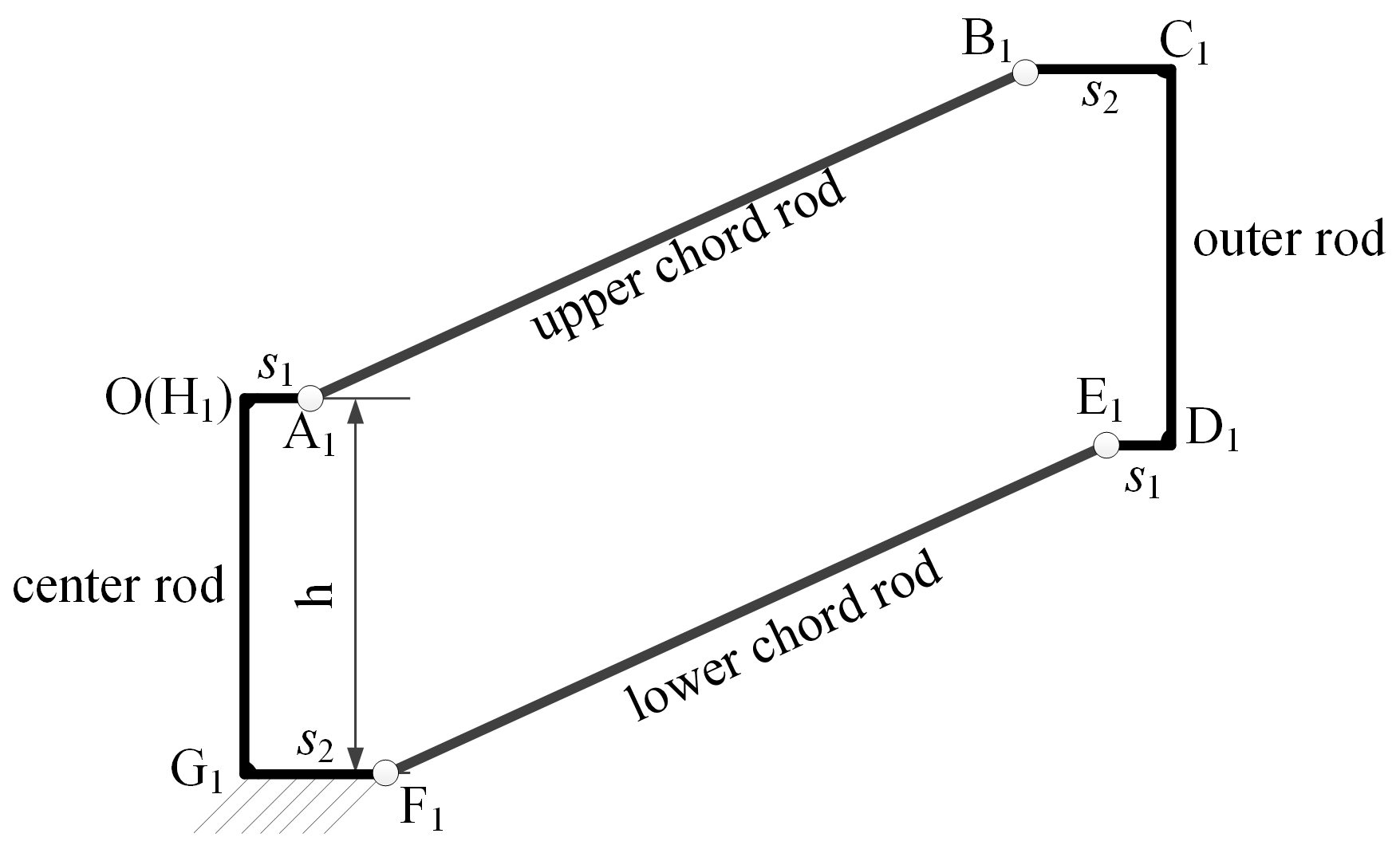
In mechanism 3, when the basic rib mechanism distributes along the axis direction, it requires that the outer rod be parallel to the center rod during movement. So mechanism 3 should be a parallelogram mechanism (basic rib mechanism 1), as shown in Fig. 5. In basic rib mechanism 1, the nodal coordinates of the center rod and outer rod of the parallelogram mechanism are given. In order to obtain the nodal coordinates of the inner hinge points, it is necessary to give the lengths of the center rod and outer rod, such as s1 and s2, as shown in Fig. 5. Then the coordinates of points A1, B1, C1, and D1 can be obtained, and then the length LA1B1 can be calculated from these coordinates.
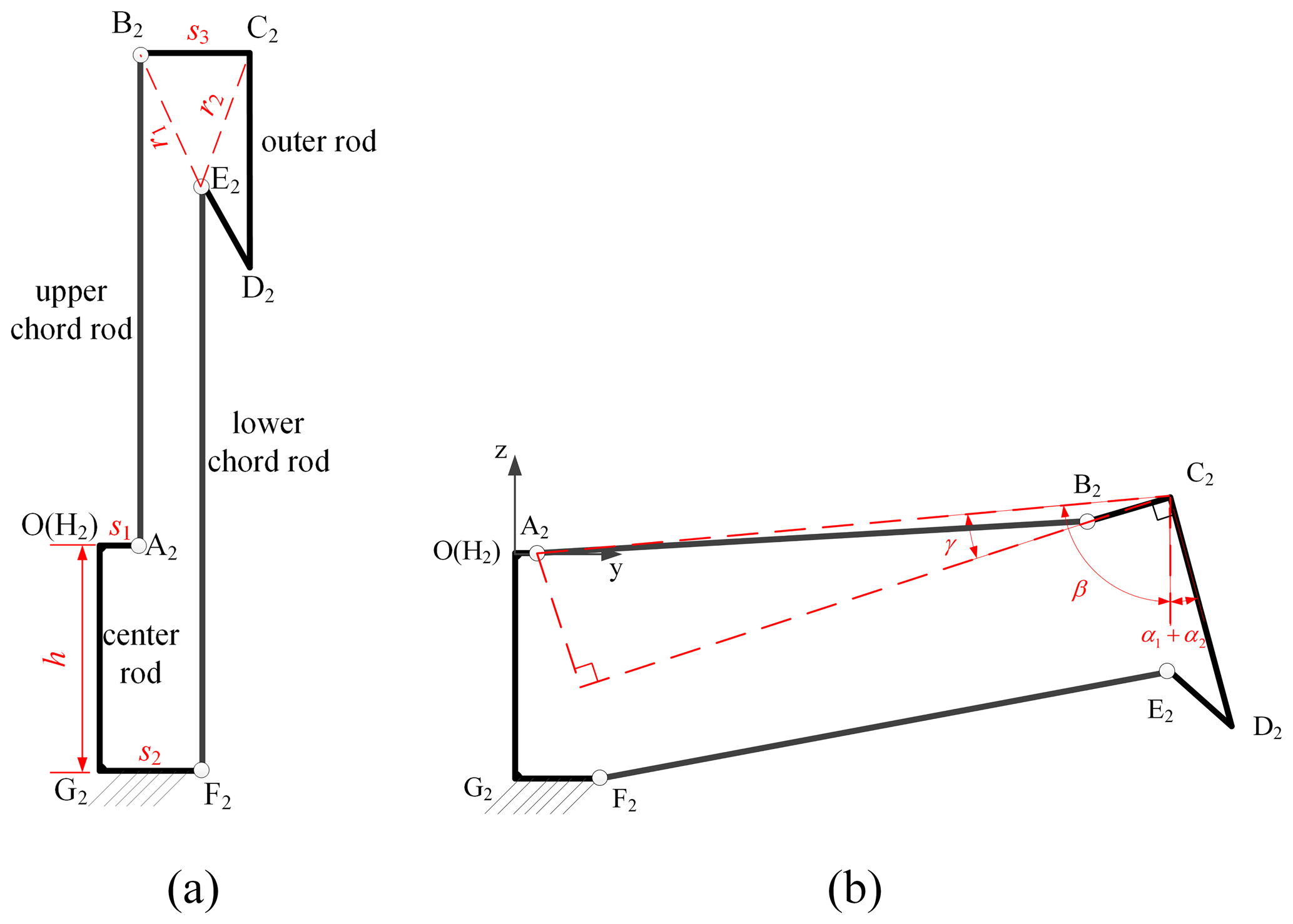
For basic rib mechanism 2, mechanism 3 should be a planar four-bar mechanism because the angle between the outer rod and center rod needs to change during movement. In order to determine the nodal coordinates of the inner hinges of a planar four-bar mechanism in a completely deployed state, the drawing method is used to derive the position of each member in a completely deployed state, together with geometric relationships of the mechanism in the folded state. The folded and deployed states of the planar four-bar mechanism are shown in Fig. 6. The fully folded state is rectangular, as shown in Fig. 6a. The heights of all rib mechanisms are equal, and they yield the following:
According to the geometric relationship of the mechanism between the folded state and the deployed state shown in Fig. 6b, we can obtain the value of s3 as follows:
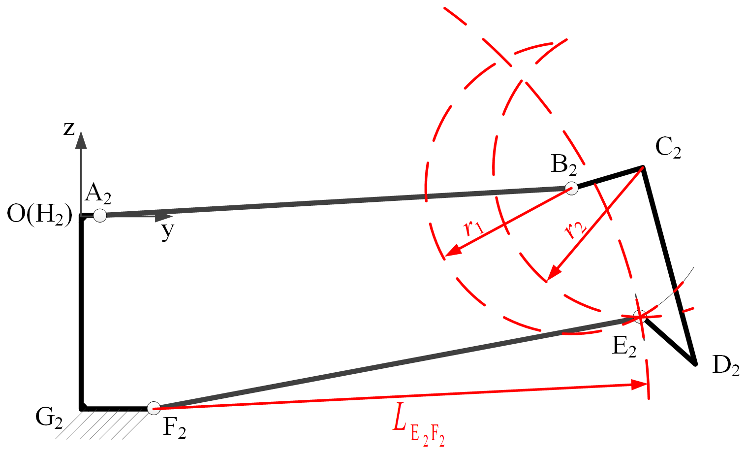
In Fig. 6b, points C2 and D2 correspond to nodes P9 and P2 in Fig. 1b. Because point C2 in the deployed state is on the fitting cylindrical surface, the coordinates of points C2 and D2 are known. Then the coordinate of point B2 in the deployed state can be obtained, according to the values of and s3. The remaining coordinate of point E2 in the deployed state is obtained by the drawing method. Three circles are drawn in Fig. 7, and their intersection is the coordinate of point E2. Thus, we have the following:
where , and . By solving Eq. (5), we obtain the values of , , and .
When deployable modules are connected along the axis direction of a parabolic cylinder, there is only translation and no rotation. So, its geometric connection transformation matrix is as follows:
where E is a third-order unit vector, pi is a translation vector, and
The coordinate of point 0 at the first module is 10Pj, as shown in Fig. 1b. After topology transformation along the axis direction of parabolic cylinder, the coordinate 10Pj in the ith module is as follows:
When deployable modules are connected along the parabolic direction of parabolic cylinder, there is both translation and rotation. Thus, the topology transformation matrix is the following:
Here Rj is rotation matrix, pij is the translation vector, and is calculated as the following:
If the coordinate in the first module is known after a topological transformation along the parabolic direction, the coordinate in the (i×j)th module is as follows:

If the parabolic cylinder antenna is composed of 10 hexagonal prism modules, as shown in Fig. 8, we have and for Eqs. (6)–(8) and , , and for Eqs. (9) and (12).
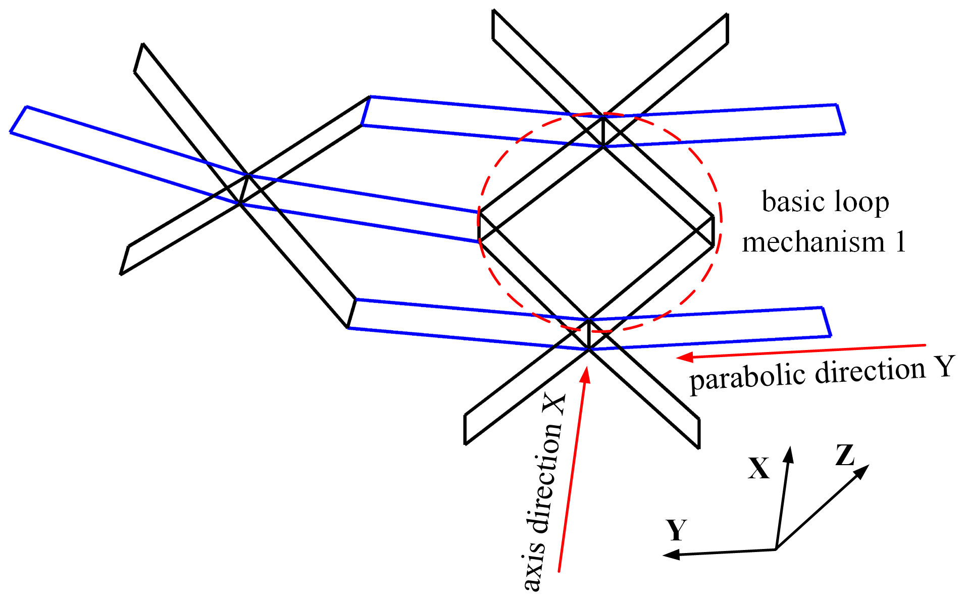

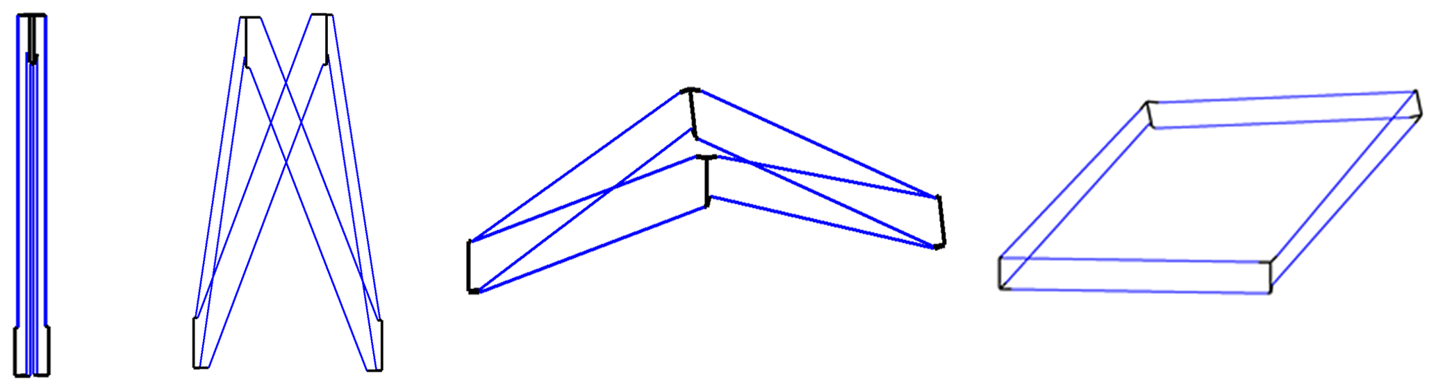
As shown in Fig. 2, the basic rib mechanism is a planar mechanism. According to the Grübler–Kutzbach formula (Guo et al., 2019), its degree of freedom is 1. When three hexagonal prism modules are contacted, two types of mechanism loops will be generated, as shown in Figs. 9 and 10. When the modules are geometrically connected along the axis direction of parabolic cylinder, the basic loop mechanism 1 is formed by the adjacent modules, as shown in Fig. 9. The basic loop mechanism 1 is a biaxial symmetric mechanism, which is composed of four of the same basic rib mechanisms, i.e., rib mechanism 1, so its degree of freedom is 1.
When the modules are connected along the parabolic direction, a basic loop mechanism 2 is formed, as shown in Fig. 10. It consists of rib mechanisms ➀, ➁, ➂, and ➃. ➀ and ➃ are basic rib mechanism 1 and have same geometric parameters. Mechanisms ➁ and ➂ are basic rib mechanism 2 and have same geometric parameters. Moreover, the basic loop mechanism 2 is an elementary motion unit in the deployable mechanism. The degree of freedom analysis of the elementary motion unit has great significance for the smooth deployment of the deployable mechanism.
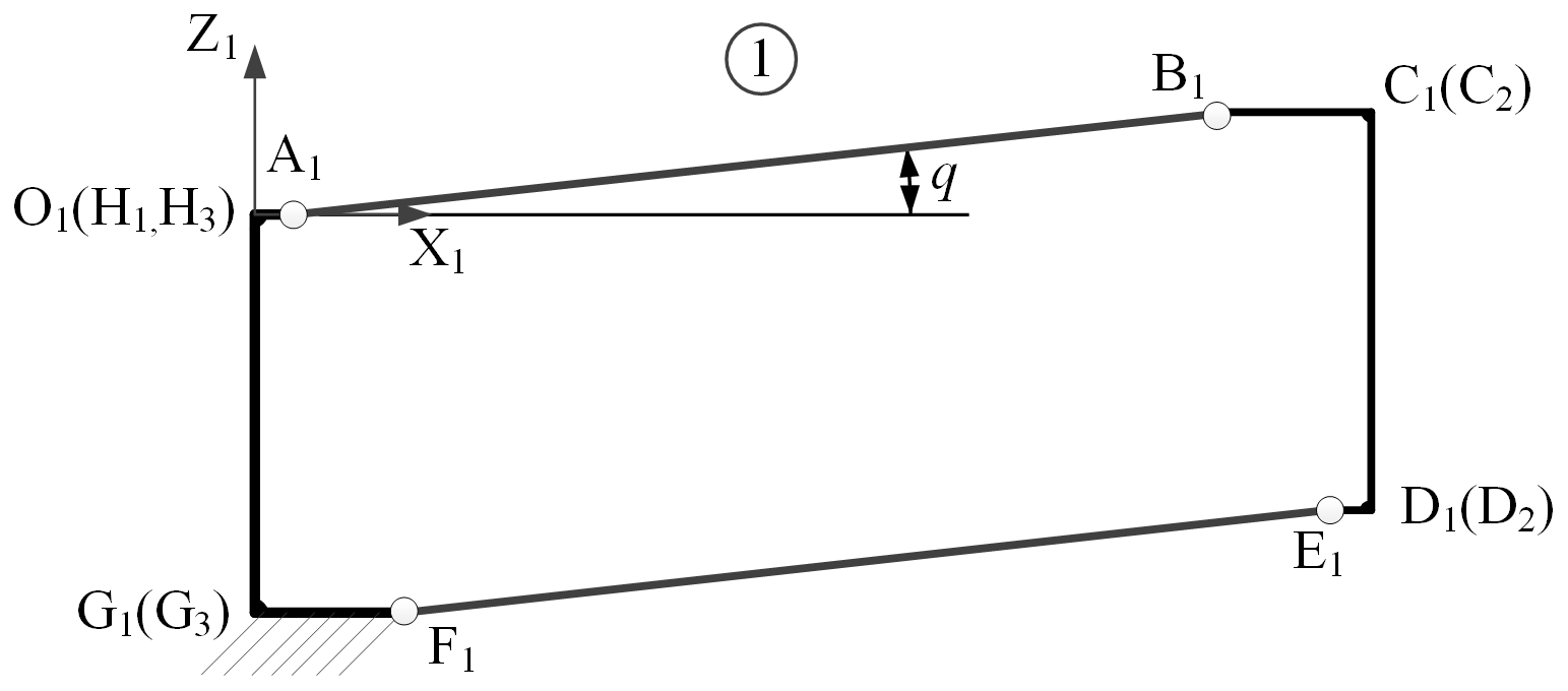
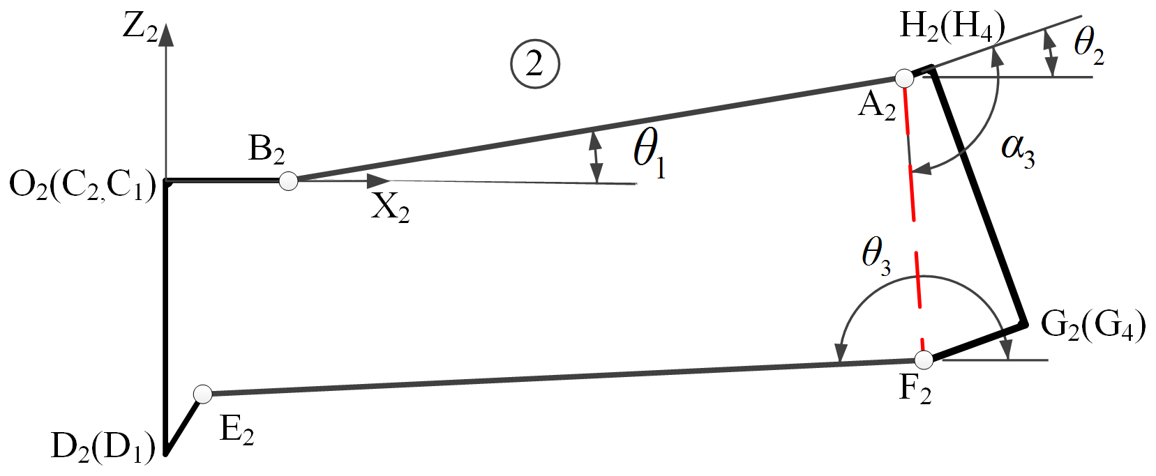


The details of planar rib mechanisms ➀, ➁, ➂, and ➃ are shown in Figs. 11–14, respectively, where O1, O2, O3, and O4 are the origins of local coordinate system.
The planar rib mechanisms ➀ and ➃ are parallelogram mechanisms, and they belong to the basic rib mechanism 1. There exists, in the local coordinate system of O1-X1Z1 and O4-X4Z4, the generalized variable q and θ7 for the planar rib mechanisms ➀ and ➃, respectively. The planar rib mechanisms ➁ and ➂ are ordinary four-bar mechanisms, and they belong to the basic rib mechanism 2. There exists, in the local coordinate system of O2-X2Z2 and O3-X3Z3, generalized variables, namely θ1, θ2, and θ3 and θ4, θ5, and θ6 for the planar rib mechanisms ➁ and ➂, respectively. In the XiOiZi () plane, we can establish its loop equation for planar rib mechanisms. According to coordinate transformation, the position equations of the basic loop mechanism 2 can be derived. The position equations are solved by the Newton–Raphson method when the generalized coordinate q is known. The relative position result of the basic loop mechanism 2 is shown in Fig. 15. It indicates that the degree of freedom of the basic loop mechanism 2 is 1.
According to the above analysis, the degree of freedom of the basic loop mechanism 2 along the parabolic direction is 1. The movements of opposite planar rib mechanisms, namely ➀ and ➃ and ➁ and ➂, are synchronized while the movements of adjacent planar rib mechanisms are not synchronized. For the hexagonal prism module shown in Fig. 1, six rib mechanisms share a driving slider, which is equivalent to adding a constraint from the viewpoint of the mechanisms. So, the degree of freedom of the basic loop mechanism 2 along the parabolic direction is 0. In order to avoid the movement interference between the basic deployable rib mechanism along the axial and parabolic directions of parabolic cylinder, this paper proposes two design schemes. The first scheme is to remove the lower supporting rod connected with the slider in the basic rib mechanism 2 that is connected with other hexagonal prism modules. The second scheme is to remove the lower supporting rod connected with the slider in the basic rib mechanism 1 that is connected with other hexagonal prism modules.
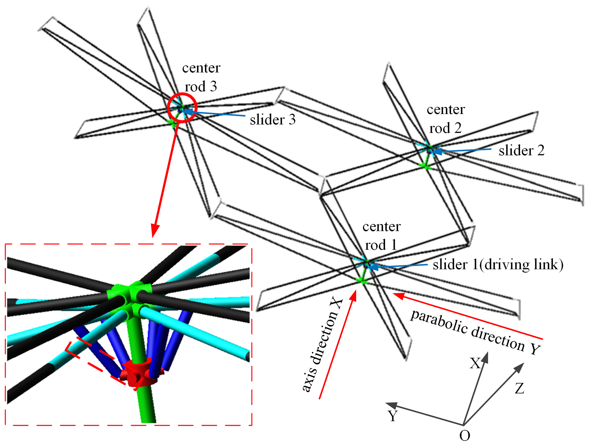
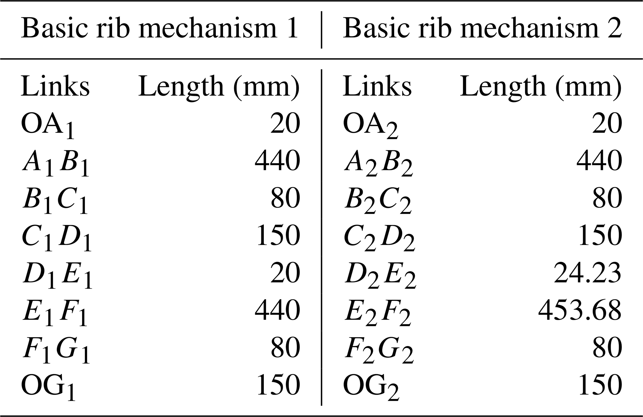
In order to verify whether the degree of freedom of the modular deployable mechanism of the first scheme is 1 and the movements of the modules are synchronized, the Automatic Dynamic Analysis of Mechanical Systems (ADAMS) multibody dynamic simulation is applied to model and analyze the typical deployable mechanism unit. The deployable mechanism unit shown in Fig. 16 is composed of three hexagonal prism modules. In the deployable mechanism, all the basic rib mechanisms 1 have the same geometrical parameters, and all the basic rib mechanisms 2 also have the same geometrical parameters. Geometrical parameters of the basic rib mechanisms are shown in Table 1.
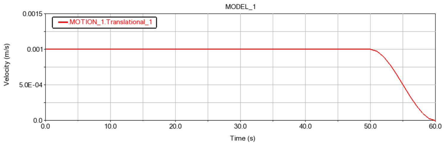
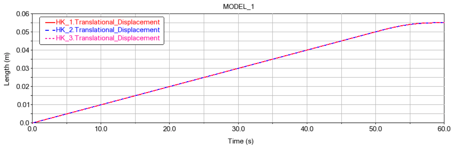
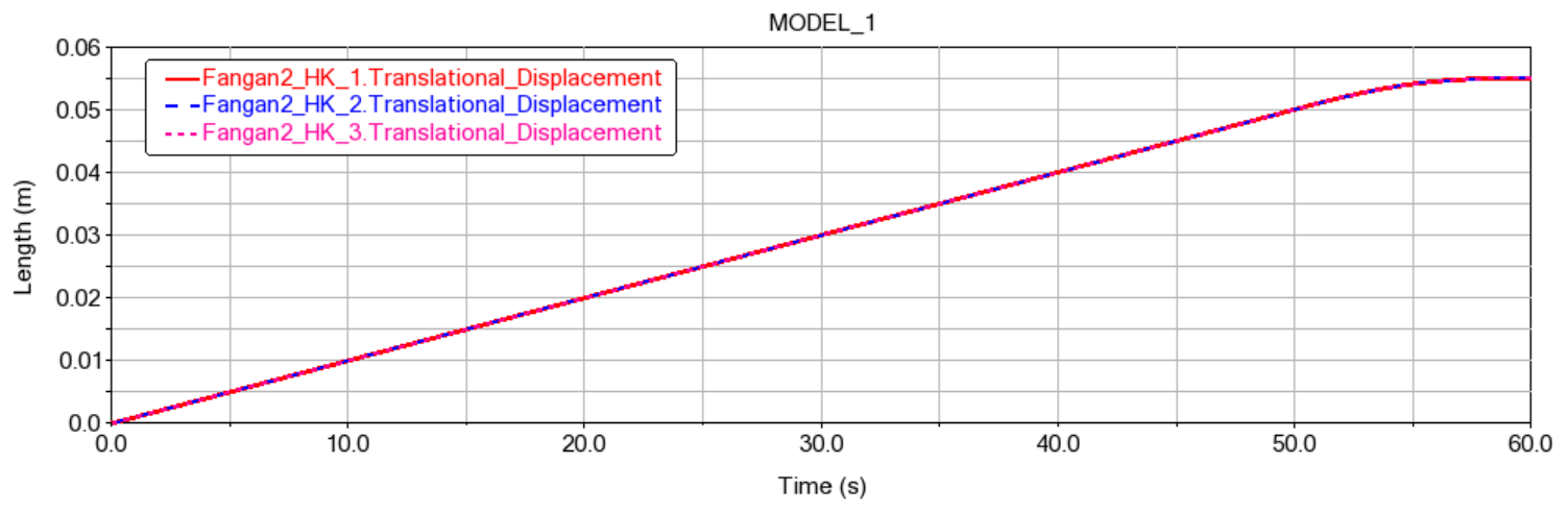
In the multibody dynamic simulation, the corresponding kinematic pairs and friction are set between components. The sliders 1–3 are located in the center rods 1–3, respectively, as shown in Fig. 16. The slider 1 is regarded as the driving link, and its speed curve is shown in Fig. 17. The folded state of the deployable mechanism unit is shown in Fig. 18. Through multibody dynamic analysis, we obtain displacement curves of sliders 1–3, as shown in Fig. 19. As it can be seen from Figs. 18 and 19, all modules can be folded and unfolded when the slider 1 is used as the driving link, and the displacement curves of slider 1–3 are highly consistent. The results indicate that the degree of freedom of the deployable mechanism unit based on the first scheme is 1, and the movements of all modules are synchronous.
In Fig. 19, the HK_1, HK_2, and HK_3 represent the slider 1, 2, and 3, respectively. The deployable mechanism unit with three modules based on the second design scheme is shown in Fig. 20. In the same way, the corresponding kinematic pairs and friction are set between the components, and the slider 1 is regarded as the driving link; its speed curve is shown in Fig. 17. The folded state of the t deployable mechanism unit based on the second design scheme is shown in Fig. 21. Through the multibody dynamic analysis, we obtain the displacement curves of slider 1–3, as shown in Fig. 22.
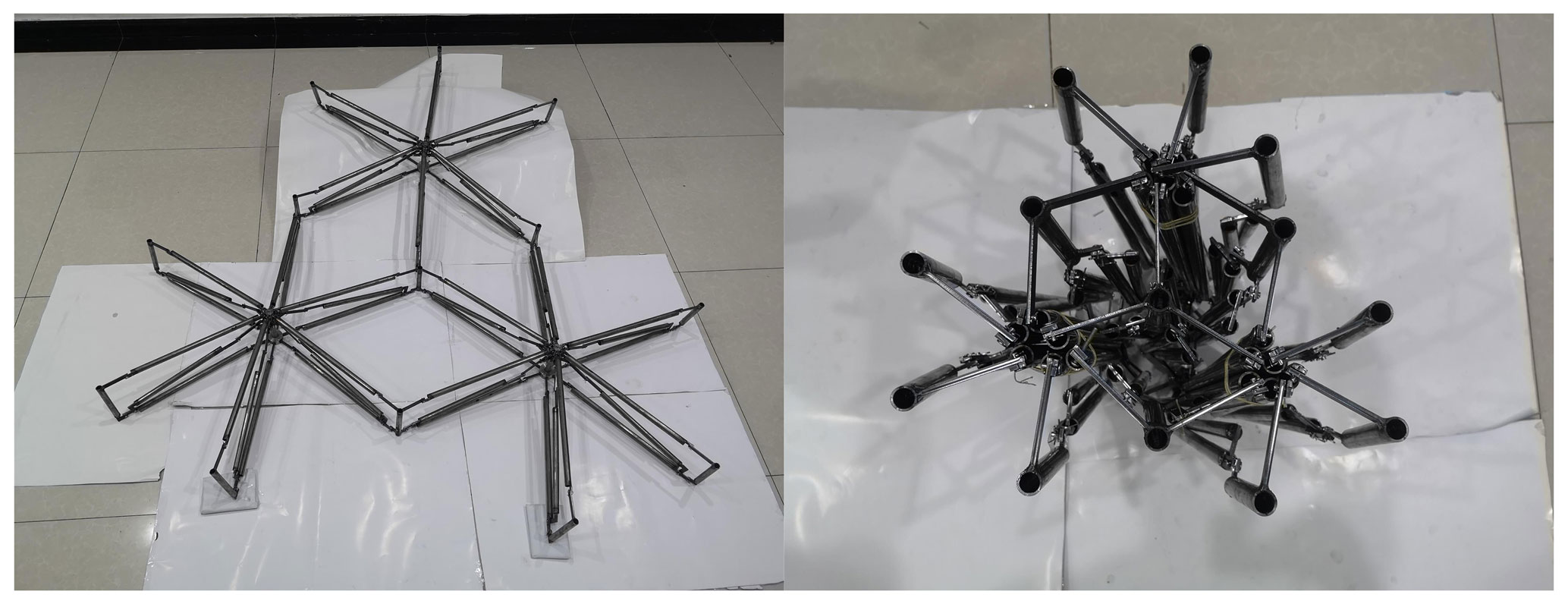
The same conclusion is summarized from Figs. 21 and 22. The degree of freedom of the deployable mechanism unit based on the second design scheme is also 1, and the movements of all modules are also synchronous. At the same time, the experimental prototype of the deployable structure unit with three modules is constructed, and the unfolded and folded states are shown in Fig. 23. The experiment verifies the feasibility of the deployable mechanism.
This paper proposes a novel deployable mechanism of parabolic cylinder antennas connected by hexagonal prism modules. In this mechanism, there is no crack at the connecting place of each hexagonal prism module. According to the geometric property of the module connection, we have designed two basic rib mechanisms to ensure the minimum fold volume of parabolic cylinder antennas by the mechanism-splitting method and the drawing method. Then, we derive the loop equation of the basic loop mechanism, generating the module connection and analyzing the degree of freedom of the basic loop mechanism. Next, we adopt two schemes to avoid movement interferences. Simulation results show that the degree of freedom of the designed mechanism is 1, the motion is synchronous for all modules, and the feasibility of the deployable mechanism is further verified by a physical prototype.
The data in this study can be requested from the corresponding author.
MX, LY, and LT proposed the idea and developed the model. DH and WD contributed to the MATLAB programming for the modeling. ZJ contributed to the prototype.
The authors declare that they have no conflict of interest.
This article is part of the special issue “Robotics and advanced manufacturing”. It is not associated with a conference.
This research has been supported by the National Natural Science Foundation of China (grant nos. U1537213 and 51775403).
This paper was edited by Guimin Chen and reviewed by two anonymous referees.
Brancart, S., Laet, L. D., and Temmerman, N. D.: Deployable textile hybrid structures: design and modeling of kinetic membrane-restrained bending-active structures, Procedia Engineer., 155, 195–204, https://doi.org/10.1016/j.proeng.2016.08.020, 2016.
Chen, Z. P., Wang, R. L., Peterson, J., Chen, X. L., and Shi, H. L.: Design and analysis of a large cylinder antenna array in Tianlai, SPIE Astronomical Telescopes + Instrumentation, 9906, 99065W, https://doi.org/10.1117/12.2232570, 2016.
Dong, B., Zhang, H., Zhang, Y., and Li, N.: Geometry modeling of truss structure for a space deployable parabolic cylindrical antenna, MATEC Web Conf., 256, 05006, https://doi.org/10.1051/matecconf/201925605006, 2019.
Guo, J. W., Xu, Y. D., Liu, W. L., and Yao, J. Y.: Mobility analysis of novel deployable mechanism based on tetrahedral element, Journal of Mechanical Engineering, 55, 9–18, https://doi.org/10.3901/JME.2019.12.009, 2019.
Im, E. and Durden, S. L.: Next-generation spaceborne precipitation radar instrument concepts and technologies, 45th AIAA Aerospace Sciences Meeting and Exhibit, Reno, Nevada, 8–11 January 2007, 1005–1013, 2007.
Lane, S. A., Murphey, T. W., and Zatman, M.: Overview of the innovative space-based radar antenna technology program, J. Spacecraft Rockets, 48, 135–145, https://doi.org/10.2514/1.50252, 2011.
Lin, F., Chen, C. Z., Chen J. B., and Chen, M.: Modelling and analysis for a cylindrical net-shell deployable mechanism, Adv. Struct. Eng., 22, 3149–3160, https://doi.org/10.1177/1369433219859400, 2019.
Liu, R. Q., Tian, D. K., Deng, Z. Q., Guo, H. W., and Liu, Z. J.: Kinematics modeling and driving spring design of truss structure for deployable truss antenna, Adv. Mat. Res., 457, 1337–1341, https://doi.org/10.4028/www.scientific.net/AMR.457-458.1337, 2012.
Song, X. K., Deng, Z. Q., Guo, H. W., Liu, R. Q., Li, L. F., and Liu, R. W.: Networking of Bennett linkages and its application on deployable parabolic cylindrical antenna, Mech. Mach. Theory, 109, 95–125, https://doi.org/10.1016/j.mechmachtheory.2016.10.019, 2017.
Spence, T., Cooley, M., Stenger, P., Park, R., Li, L., Racette, P., Heymsfield, G., and Mclinden, M.: Development of a multi-band shared aperture reflectarray/reflector antenna design for NASA, IEEE International Symposium on Phased Array Systems and Technology, Waltham, MA, 2016.
Xiao, H., Lu, S. N., and Ding, X. L.: Optimizing accuracy of a parabolic cylindrical deployable antenna mechanism based on stiffness analysis, Chinese J. Aeronaut., 33, 1562–1572, https://doi.org/10.1016/j.cja.2019.05.017, 2019.
Yu, T., Guan, F. L., and Dai, L.: Design and analysis of bidirectional deployable parabolic cylindrical antenna, J. Zhejiang. Univ.-Sc. A, 15, 83–96, https://doi.org/10.1631/jzus.A1300202, 2014.
Zhang, S. J., Zhang, S. X., and Ye, J.: A hinged ribbed parabolic cylinder antenna for space applications, Proceedings of the Seventh Asia International Symposium on Mechatronics, Singapore, 895–903, 2020.
- Abstract
- Introduction
- Design of deployable module
- Design of deployable mechanism of multiple modules
- Analysis of degree of freedom of deployable mechanism
- Simulations and experiments
- Conclusions
- Data availability
- Author contributions
- Competing interests
- Special issue statement
- Financial support
- Review statement
- References