the Creative Commons Attribution 4.0 License.
the Creative Commons Attribution 4.0 License.
 | 09 Sep 2021
Dynamic modeling and vibration analysis of a cracked 3K-II planetary gear set for fault detection
Meng Sang
Kang Huang
Guangzhi Han
Zhenbang Cheng
The 3K planetary gear system is a basic planetary transmission structure with many advantages over the 2K-H planetary gear system. However, the vibration characteristics will be more complicated due to the increase of central gears meshing with each planet gear simultaneously. In this paper, a lumped-parameter model for a 3K-II planetary gear set was developed to simulate the dynamic response. The time-varying stiffness of each meshing pair for different gear tooth root crack faults is calculated via the finite element method. By considering the effect of time-varying transmission paths, the transverse synthetic vibrations are obtained. Subsequently, the feasibilities of transverse synthetic vibration signals and output torsional vibration signals as reference for fault diagnosis are analyzed by studying the time-domain and frequency-domain characteristics of these two vibration signals. The results indicate that both the transverse synthetic vibration signals and output torsional vibration signals can be used for fault identification and localization of the 3K-II planetary gear train, and yet they both have their limitations. Some results of this paper are available as references for the fault diagnosis of 3K planetary gear trains.
- Article
(8098 KB) - Full-text XML
- BibTeX
- EndNote


Planetary gear transmission has the advantages of low weight, small size, high load capacity and large transmission ratio, etc. Thus, planetary gear reducers are widely used in mining machinery, wind power generation, automobiles, ships, and other fields. The more common types of basic planetary gearing include the 2K-H and 3K (Rao, 2014). The 2K-H type contains two central gears and a carrier arm, and the 3K type includes three center gears (sun gear s, ring gears b and e), as shown in Fig. 1a. Compared to a fixed-shaft gearbox, the vibration signal of a planetary gearbox is more complex. For a planetary gear set, each planet gear meshes with the sun and ring gear(s) simultaneously. The planet gear not only rotates around its own axis but also around the axis of the central members (sun gear, ring gear, and the carrier) (Xue and Howard, 2018). There are phase differences between each gear mesh pair (Parker and Lin, 2004), and the coupling between all the gear mesh pairs causes some of the excitations to be augmented or offset (Liang et al., 2018).
To monitor the operation of a planetary gearbox, the traditional method is to install a fixed sensor on the housing to measure the vibration signals (Mark and Hines, 2009). However, in this way, the transfer paths of the vibration signals to the sensor change due to the rotation of the carrier; the measured vibration data exists as a modulation phenomenon. McFadden (1991, 1994) and Howard (1991) presented a technique for calculating the time-domain averages of the tooth meshing vibration of the individual planet gears and the sun gear in an epicyclic gearbox. McFadden (1994) also proposed various window functions to acquire the vibration signals of each planet gear. Subsequently, numerous scholars have concentrated on the interpretation of the vibration spectrum modulation phenomenon due to the change of transmission path caused by the rotation of the carrier arm. McNames (2002) made use of Fourier series analysis to account for the asymmetries observed in the spectrum and predicted the possible locations of the major spectral constituents. Inalpolat and Kahraman (2009, 2010) applied a Hanning window function to represent the periodic varying of the transfer path from vibration source to transducer due to the rotation of the carrier and analyzed the modulation sidebands of the planetary gear system in five possible situations. Furthermore, Liang et al. (2015) and Liu et al. (2016) used the Hamming and the Hanning window function with different parameters to indicate the transmission path effects. Recently, Li et al. (2019) tested the time-varying transfer path function of a 2K-H planetary gear system by an experimental method based on the modal reciprocity principle.

Figure 1The 3K-II planetary gear set: (a) three-dimensional model; (b) Force analysis of each gear.
As a signal gauged from the gear axle, torsional vibration conveys the operational information of the gearbox as well (Addabbo et al., 2019). Assuming that all the gears of a planetary gear set are isotropic on the circumference, the propagation distance from the meshing locations of each gear pair to the torsional vibration sensor is invariant. Therefore, torsional vibration analysis is an optional method of planetary gearbox condition monitoring. Feng and Zuo (2013) offered clear formulas to describe the torsional vibration signals for a planetary gearbox. It was shown that the torsional vibration signal is modulated only by the fault frequency. Zeng et al. (2017) developed instantaneous angular speed (IAS) measurement systems for planetary gear train fault diagnosis and examined its validity by an experimental method. Zhao et al. (2018) introduced a Kurtosis-guided partial multinomial differentiator to evaluate the IAS, and based on that a method for fault detection of planetary gearboxes was presented. Moreover, Xue and Howard (2018) also analyzed the feasibility of torsional vibration signals as a fault diagnosis tool for planetary gearboxes using some general signal processing technologies.
Kinetic analysis is a better approach to study the vibration characteristics of a planetary gear set. Compared to mathematical models (Inalpolat and Kahraman, 2009; Li et al., 2019; Feng and Zuo, 2013), a dynamical model can more accurately characterize the physical parameters of a gear system, such as time-varying meshing stiffness and damping, and it helps to understand the effects of various types of gear faults on planetary gearboxes. Many dynamical models have been proposed to obtain the dynamic performance of epicyclic gearboxes. Kahraman (1994) developed a kinetic model for a 2K-H planetary gear set to study the load distribution properties. Based on the model in Kahraman (1994), Lin and Parker (1999) developed a lumped-parameter dynamics model considering the effects of meshing phase difference, time-varying meshing stiffness, and carrier rotation. Then the free vibration characteristics of a 2K-H planetary gearbox were investigated. Subsequently, the nonlinear dynamical behavior was studied, and the comparison with a 2D finite element model was carried out to prove the effectiveness of the lumped-parameter model (Ambarisha and Parker, 2007). Li et al. (2014) developed a dynamic model for a multistage planetary gear train and analyzed the influences of damping, backlash, and excitation frequency on system dynamic characteristics. Additionally, some scholars have also investigated the effects of manufacturing errors, cracks, wear, backlash, breakage, and other factors on the dynamic characteristics of planetary gearboxes by means of establishing a dynamical model (Chaari et al., 2006; Liu et al., 2018; Sun et al., 2019; Xiang et al., 2018; Wu et al., 2017; Liu et al., 2019).
Literature studies mentioned previously indicate that a large range of studies have been conducted for the dynamic characteristics and vibration signal analysis of planetary gear systems. However, most of them focus on 2K-H. As another basic planetary gearing, the 3K planetary gear system is more compact than the 2K-H planetary gear system and offers a larger transmission ratio range. The vibration properties of a 3K planetary gear set would be more complex as each planet gear meshes with more central gears simultaneously. Few pieces of literature could be found on vibration investigations of the 3K planetary gear set. Song et al. (2009) presented a dynamics model for a 3K-II planetary gear set by decomposing it into two 2K-H planetary gear trains and analyzed the inherent characteristics. Nevertheless, the force direction of the gears was not considered in Song et al. (2009).
In this paper, a dynamic model of the 3K-II planetary gear train is proposed by considering the force on each gear, as shown in Fig. 1b. Taking into account the phase difference between each meshing pair, the time-varying meshing stiffness with different types of tooth root crack faults was analyzed by the finite element method. Supposing the sun gear s is the input component and the ring gear e is the output component, then the transverse synthetic vibration signal and output torsional vibration signal at healthy cases and five cracked tooth root cases are simulated. Both the vibration characteristics of these two signals are investigated. Some results are considered references for the fault detection of 3K planetary gear trains.
2.1 Dynamic model of a 3K-II planetary gear train
In this section, a mathematical planetary gear transmission model is developed to help understand the complex dynamic response of a 3K-II planetary gear system, as shown in Fig. 2. This model contains an input torque, a sun gear, a carrier arm, three planet gears, two ring gears, and an output load. Similar to the model used by Liang et al. (2015), each component of this model has three DOFs (degrees of freedom): one rotation and two transverse motions in the x and y directions. The rotational coordinates of the carrier c, ring gear b, ring gear e, sun gear s, and planet gears pn ( are the absolute angular displacements of each component. The transverse motions are measured in a rotational coordinate system fixed to the carrier rotating around rotation center o. The mesh internal force of gear pairs and the bearing support are described as a spring–damper system. The are the angles measured relative to planet gear 1. The initial position (time zero) is displayed as Fig. 2; i.e., ψ1=0.
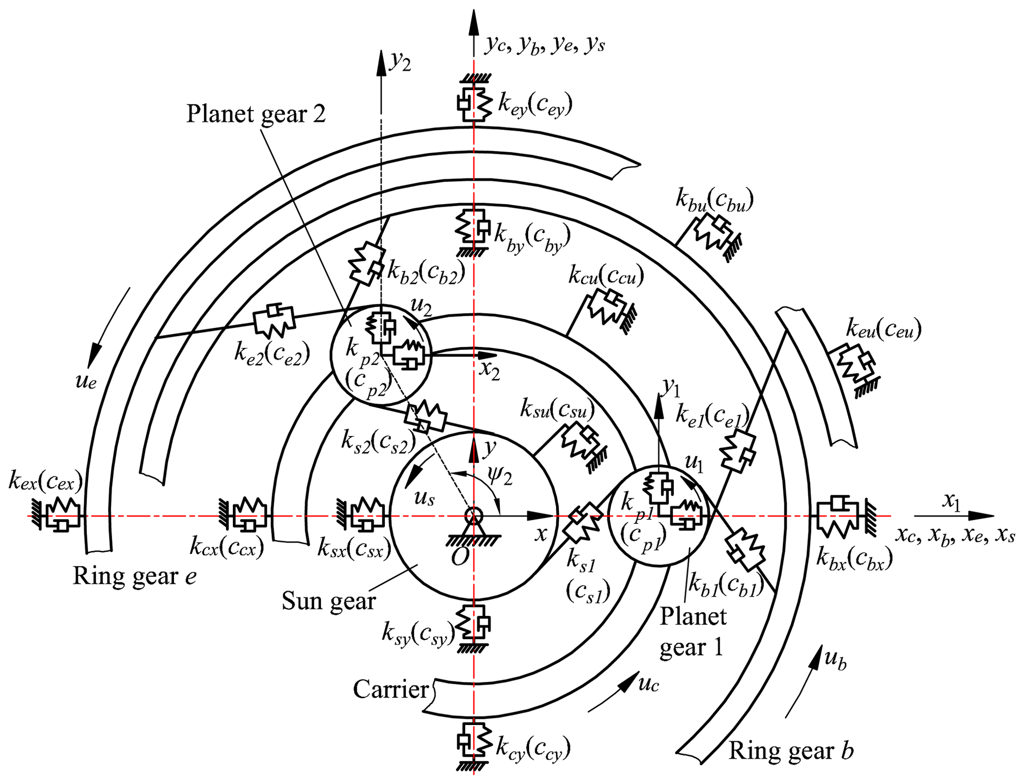
It is worth noting that the tangential force of each planet gear applied by ring gear b and ring gear e is in opposite direction. That is, ring gears b and e mesh with different sides of planet gear teeth. This conclusion is obtained from the force analysis described in Fig. 1b. It is found from the force on planet gear p that the direction of tangential force Fep is opposite to that of the other two. This is because the ring gear e has a smaller pitch radius than ring gear b. This phenomenon is also applicable to 3K-I and 3K-III planetary gear sets. Since we mainly focus on the effects of a tooth root crack on different gears on the vibration response, the static transmission error, the friction, and the backlash between gear pairs are not considered in this paper. The equations of motion of the planetary gear set are achieved based on lumped-parameter method as follows.
Motion equations of the sun gear:
where Fspn is the dynamic force between the nth planet gear and the sun gear,
Motion equations of the ring gear b:
where Fbpn is the dynamic force between the nth planet gear and the ring gear b,
Motion equations of the ring gear e:
where Fepn is the dynamic force between the nth planet gear and the ring gear e,
Motion equations of the planet gears:
in which Fcpnx and Fcpny are the support forces between the nth planet gear and carrier in the x and y directions.
Motion equations of the carrier:
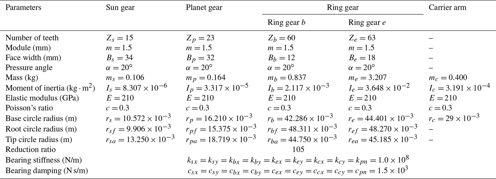
All the notations of nomenclature used in this paper are explained in Appendix A, the selected parameters of the 3K-II planetary gear set are listed in Table 1, and the number of the planet gears is three.
2.2 Crack mesh stiffness calculation
Crack is a typical form of failure in gear transmission trains. The existence of a crack will weaken the bearing capacity of the gear tooth and even break the tooth. Stiffness excitation is one of the most important internal excitation forms in gear transmission. When a crack develops on the gear tooth, the mesh stiffness will be reduced, and the vibration properties of the gear transmission train will be changed.
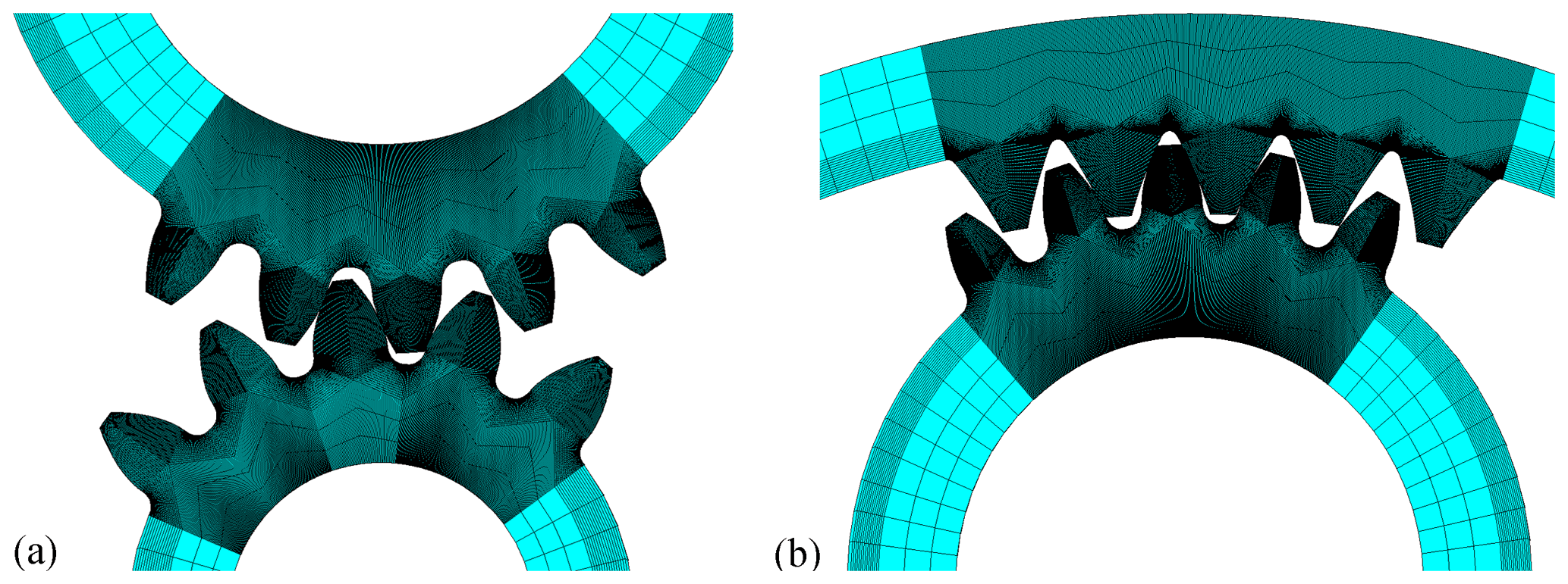
Compared with the stiffness calculated by the potential energy method (PEM), the finite element method (FEM) results describe the crack characteristics more accurately. And the finite element method includes coupling flexibility of adjacent teeth and avoids repeated superposition of tooth base stiffness. The FEM model of an external gear pair used in this paper is shown in Fig. 3a, and the internal gear pair is displayed in Fig. 3b. The elements of the teeth are refined to ensure the accuracy of the calculation results. The hubs of the driven wheel and the driving wheel are rigidly coupled with their respective centers. The load is applied to the rotating shaft of the driving gear, and all the degrees of freedom of the driving and driven gears are limited except the axial rotation of the driving gear. All the calculations are completed in ANSYS (engineering simulation and 3D design software); then the comprehensive meshing stiffness is expressed as the following: , where Tload is drive torque, Δθ is the rotation angle of the driving gear after the deformation under load, and rdriving is the base radius of the driving gear.
To present the influence of cracks of different gears on the vibration characteristics of the system, a linear crack with constant crack angle (65∘) and constant length (1.32 mm) is applied in both the internal and external gear pairs in this section, as shown in Fig. 4.

There are five crack cases in this study: case I, i.e., the sun gear with a root cracked tooth; case II, i.e., a planet gear with cracked tooth root (sun gear s-ring gear e side); case III, i.e., a planet gear with cracked tooth root (ring gear b side); case IV, i.e., the ring gear b with a root cracked tooth; and case V, i.e., the ring gear e with a root cracked tooth. In all the above conditions, some will affect the gear meshing stiffness in all branches, while others will not. To display the impact of various cases on the system meshing stiffness, all the summary information is included in Table 2. When the carrier rotates one round, all the planet gears return to their original positions, and all the teeth of each gear are meshed at least once. To include all the tooth crack fault signals, all the information in Table 2 is based on the observations over one carrier revolution. In Table 2, kjpn (where ; ) denotes the meshing stiffness of the nth s−p, b−p, and e−p mesh pairs, respectively. γjn (where ; ) is the mesh phase difference of the sun gear s, ring gear b, and ring gear e meshes, individually, between each planet gear and the first planet gear. γse1 is the mesh phase difference between the s−p and e−p mesh pairs of the first planet gear. In this paper, according to the parameters listed in Table 1, all these phase differences are obtained as , and γse1=11.4372 (Parker and Lin, 2004). θm is the rotation angle of carrier within a meshing period and is equal to (6∘).
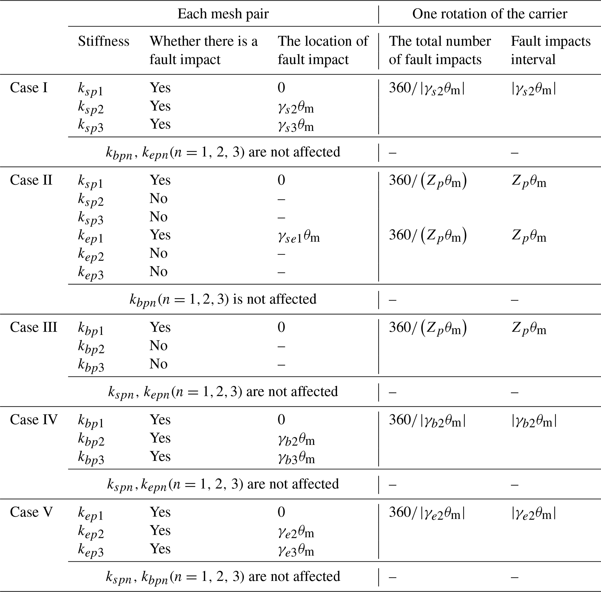
Figure 5a shows the effect of tooth crack on s−p meshing stiffness values in case I. It can be found that all the s−p meshing stiffness values are influenced. The fault interval is |γs2θm|(30∘), and there are 12 fault impacts covering one carrier revolution. According to the force analysis of the 3K-II planetary gear system, the sun gear s and the ring gear e meshed with the same tooth side of the planet gear, while the ring gear b meshed with the other tooth side. Since the existence of a crack mainly affects the bending and shear stiffness values (Chen et al., 2019), the crack on a different flank from the meshing surface can be considered to have no influence on the meshing stiffness. In other words, in case II, only one s−p and one e−p meshing stiffness values are affected, while in case III only one b−p was affected. The influence of case II and case III on the meshing stiffness of this 3K-II planetary gear system is shown in Fig. 5b and c, respectively. In both of these two cases, the total number of fault impacts is three, and the fault interval is Zpθm(138∘). As for case IV and V, all the planet branches are affected, which is similar to case I. As illustrated in Fig. 5d and e, the fault intervals are |γb2θm|(120∘) and individually, and there are three fault impacts for both.

Figure 5Meshing stiffness curves affected by crack faults: (a) case I; (b) case II; (c) case III; (d) case IV; (e) case V.
2.3 Analysis of fault characteristic spectrum
Meshing frequency is an important property in the vibration analysis of a gear transmission train. For the 3K-II planetary gear set, since each planet gear meshes with all central gears simultaneously, the meshing frequency of each mesh pair is the same. Considering that the ring gear b is fixed, the meshing frequency is described as the following (Xue and Howard, 2018):
in which fc is the carrier rotational frequency. In case I, since each planet branch is affected, the fault characteristic frequency is given by
where N is the number of planet gears, and is the shaft frequency of sun gear relative to the carrier. For single planet gear failure (cases II and III), only one planet branch is affected, and the fault characteristic frequency is written as
where is the shaft frequency of fault planet gear with respect to the carrier. As for the local ring gear crack (cases IV and V), it is similar to case I, and the fault characteristic frequency is written as
where and are the rotational frequency of ring gears b and e relative to the carrier, respectively.
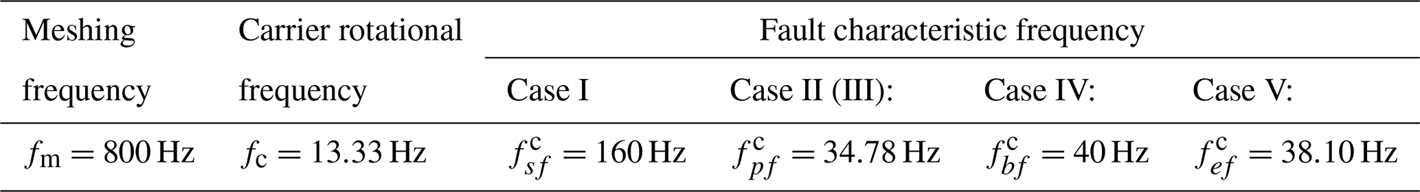
Vibration analysis is a common method used in mechanical fault detection. For planetary reducers, a common approach is using a sensor mounted on the fixed housing to monitor the gear system (as shown in Fig. 1). In this section, the vibration properties of each component of the 3K-II planetary gear system are obtained by solving the differential Eqs. (1)–(5). The output torque is limited to a constant value equal to 200 N m, and the input speed is maintained at 4000 rpm. For this operating condition, each characteristic frequency in Sect. 2.3 is listed in Table 3. For a complete rotation of the carrier, a transducer fixed on the housing experiences disturbances from all gear meshes in sequence. Considering the suppression effect of the great bearing damping and long transmission lengths on vibration signal, three force transmission paths, as shown in Fig. 1, are mainly considered in this paper. They can be simplified as follows.
-
Path 1: gear pair b−p mesh points, ring gear b, housing, sensor;
-
Path 2: gear pair s−p mesh points, planet gear p, ring gear b, housing, sensor;
-
Path 3: gear pair e−p mesh points, planet gear p, ring gear b, housing, sensor.
Considering that all the above transfer paths pass through the planet gear and that each planet gear contacts with the sun gear s, and the ring gears b and e simultaneously, the vibration of planet gears contains the information about s−p, b−p, and e−p mesh pairs. In this paper, the vibration signals of each planet gear are used to reflect the vibration signals obtained by housing-mounted sensors of a 3K-II planetary gear system, and it is represented as follows:
in which wn(t) is the time-varying transfer path function of the nth planet gear, N is the number of planet gears, and an(t) represents the nth planet gear acceleration signal.
Table 3Each characteristic frequency for a given operating condition.
3.1 Time-varying transfer path function
With the rotation of the carrier, the distance from each mesh point to the stationary sensor varies periodically. The period is the carrier rotating period. When the nth planet gear is at its closest to the sensor, its influence on the measured signal would reach its maximum, and the influence is minimized as the planet moves away from the sensor to the farthest point.
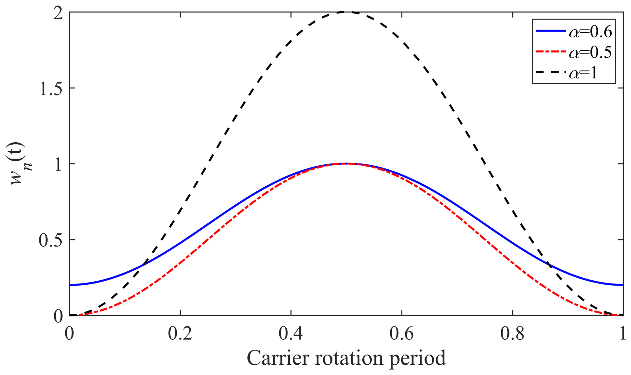
One reference (Inalpolat and Kahraman, 2009) used a Hanning window function to describe this change and assumed that each planet gear's individual effect on the sensor only persists for a time interval of , where Tc is the revolution period of the carrier. Based on that assumption, the influence of a planet gear at the farthest location from the sensor would decrease to zero, and the continuous periodic effects of each planet gear during a rotation of the carrier are ignored. This is inconsistent with the actual situation. A weighting window function Eq. (12) mentioned in Liu et al. (2016) is used in this study.
where α is limited in the range of to control the bandwidth and minimal value of the window function, ωc is the rotation speed of carrier, and is the initial phase angle for the nth planet gear.
Figure 6 shows the effect of coefficient α on the transfer path function wn(t). It can be found that when α≤0.5, wn(t) might be less than or equal to 0, and when α≥1, wn(t) would have values greater than 1. These situations are not acceptable. In view of this, the value of α is chosen to be equal to 0.6 in this paper.
3.2 Characteristic analysis of transverse synthetic vibration signals
Using the MATLAB ODE (ordinary differential equation) solver to solve the differential Eqs. (1)–(5), the acceleration signal of each planet gear in a rotational coordinate system fixed to the carrier can be obtained. To obtain the absolute acceleration in a fixed coordinate system fixed to the housing, the coordinate transformation theory is adopted (Hibbeler, 2004). Since the sensor just measures the vibration signal in a single direction, only the vertical acceleration signal is considered in this paper.
Figure 7 shows the vertical synthetic acceleration signals of a 3K-II planetary set at six different cases (the healthy gear case; failure case I, sun gear cracking; failure case II, planet gear cracking on the s−e side; failure case III, planet gear cracking on the b side; failure case IV, ring gear b cracking; and failure case V, ring gear e cracking). Affected by the carrier rotation, synthetic vibration signals present an obvious amplitude modulation phenomenon. It can be found that when there is a fault, it will affect the amplitude of the synthetic vibration signal. However, due to the amplitude modulation phenomenon, its fault characteristics of the time-domain signal are not obvious enough to be used for accurate fault location. In view of this, the frequency spectrum and cepstrum are used in this section to highlight fault features.

Figure 7Synthetic vibration signals in the vertical direction: (a) healthy gear case, (b) failure case I, (c) failure case II, (d) failure case III, (e) failure case IV, and (f) failure case V.
Figure 8 illustrates the frequency spectrum of the synthetic vibration signals in different gear health cases. To highlight the various fault frequency components, we select a frequency range from 1130 to 1270 carrier rotation frequency orders to demonstrate the spectrum characteristics. The first significant observation from these figures is that the amplitude at the mesh frequency fm and its harmonics tend to be close to 0 in all kinds of gear health cases. Still, it has sizable amplitudes at nfm±mfc (m and n are integers), like 1138, 1142, 1201 carrier order, and so on. As mentioned previously, each gear component fault will generate its fault characteristic frequency. The amplitudes at these fault frequencies could be used for fault diagnosis.
For failure case I with a cracked sun gear, the amplitudes on the positions of the sideband frequency (; m, k, and n are integers) increase significantly relative to the healthy case, as shown in Fig. 8a–b. For instance, the amplitude at frequency 1169fc (; fm=60fc, ) is found to be 1.6 m/s2 compared with the value of 0.03 m/s2 in the healthy case. There are many other options as well, like 1157fc, 1190fc, 1210fc, and so on.
For failure cases II and III with a cracked planet gear, the frequency components on the positions of the planet gear characteristic frequency (; m, k, and n are integers) in Fig. 8c–d have sizable amplitudes relative to the healthy case. For instance, the amplitude at frequency 1219.87fc (; fm=60fc, ) in Fig. 8c is found to be 0.73 m/s2 compared with the value of 0.09 m/s2 in the healthy case. The amplitude of the same location in Fig. 8d could be investigated to be 0.69 m/s2. The difference between cases II and III is that the amplitude of case II at the fault characteristic frequency of planet gear is greater than that of case III. It is caused by the coupling effect of the excitation of the s−p and e−p mesh pairs.
For failure case IV with a cracked ring gear b, the characteristic frequency of ring gear b is (m, k, and n are integers). As shown in Fig. 8e, the amplitude of the corresponding position of the characteristic frequency rises obviously relative to the healthy case. For instance, the amplitude at frequency 1149fc (; fm=60fc, is found to be 2.33 m/s2 compared with the value of 0.03 m/s2 in the healthy case.
For failure case V with a cracked ring gear e, the sizable sidebands in Fig. 8f appear at the position (m, k, and n are integers). For instance, the amplitude at frequency 1151.43fc (; fm=60fc, ) is found to be 0.98 m/s2 compared with the value of 0.18 m/s2 in the healthy case.
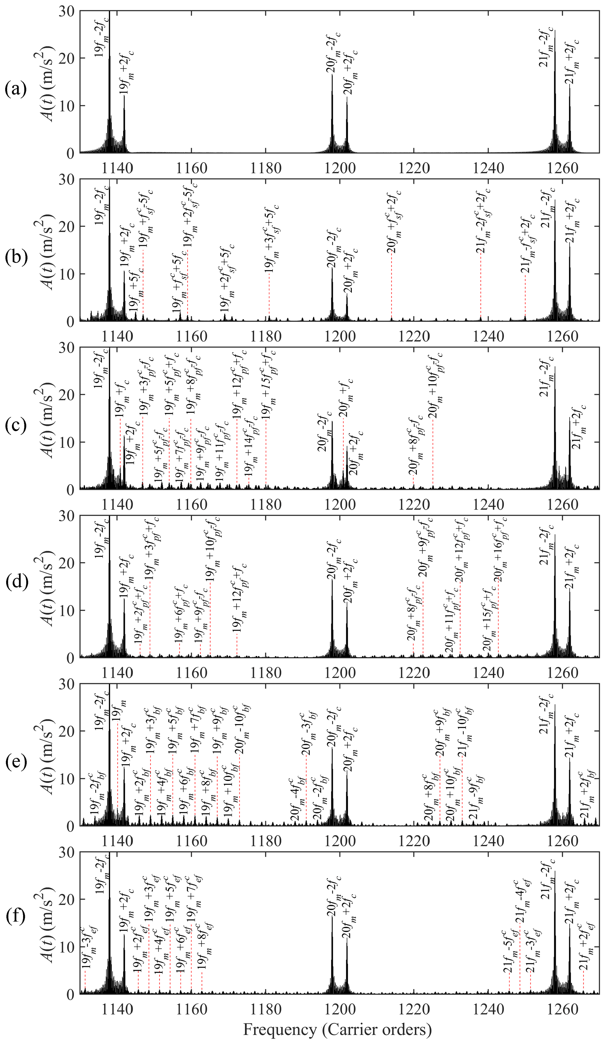
Figure 8Frequency spectrum of synthetic vibration signals: (a) healthy gear case, (b) failure case I, (c) failure case II, (d) failure case III, (e) failure case IV, and (f) failure case V.
A big challenge of comparing the frequency spectra (Fig. 8a–f) is that there are so many period components, like the meshing frequency, the carrier rotational frequency, and four fault characteristic frequencies. It is hard to determine which periodic features make up these sizable sideband components. The cepstrum is used to show the frequency components of a signal from the time dimension to highlight the periodic features which are not apparent in the original spectrum. As displayed in Fig. 9b, the amplitude at 0.00625 s () shows a massive increase, which corresponds to the case of the cracked sun gear. In the case with a cracked planet gear, the amplitude of the component at 0.02875 s () increases markedly, as shown in Fig. 9c–d. Similarly, the corresponding amplitude changes of the inverted frequency components at 0.025 s () and 0.02625 () in Fig. 9e–f can also be used to locate the ring gear faults of b and e, respectively.
According to the analysis above, we can see that the transverse vibration signal detected by the sensor fixed to the housing can be used as a basis for distinguishing faults of the 3K-II planetary gear set. However, due to the modulation phenomenon caused by the carrier arm's rotation, the sideband component of the signal frequency domain becomes complicated and the signal fault characteristics are not distinct enough. This makes it troublesome to diagnose faults via housing vibration signals.
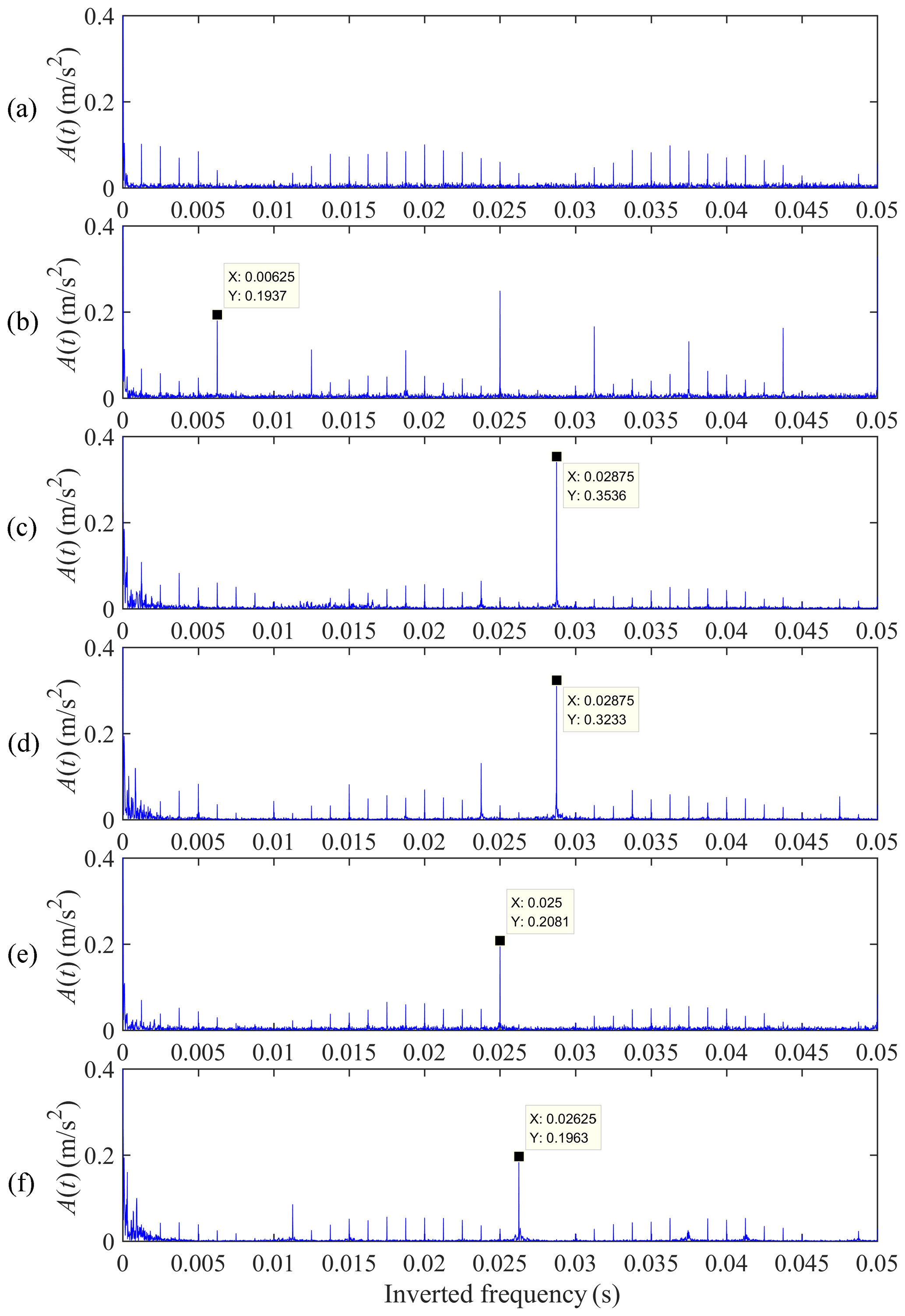
Figure 9Cepstrum of synthetic vibration signals: (a) healthy gear case, (b) failure case I, (c) failure case II, (d) failure case III, (e) failure case IV, and (f) failure case V.
Instantaneous angular speed (IAS), as a detectable signal, is commonly used in operation monitoring and fault detection of rotating machinery such as motors, gears, bearings, etc. (Kazienko and Chybowski, 2020; Wang et al., 2020; Liu et al., 2020). Compared to vibration signals detected by sensors fixed on the case, the IAS signal is not affected by the amplitude modulation caused by the rotation of the carrier arm. Besides, the IAS signal shows better sensitivity to different types of mechanical faults involving a large number of sideband orders. In this section, the same operating conditions in Sect. 3 are selected to obtain the IAS of the output ring gear e. Likewise, the time-domain spectrum, frequency spectrum, and cepstrum of the angular velocity of ring gear e are given, as shown in Figs. 10–12. Similarly, a frequency range from 350 to 440 carrier rotation frequency orders is selected in Fig. 11 to display the various failure characteristics. The frequency component of the ring gear e angular velocity signal is concentrated at the meshing frequency and its harmonics.
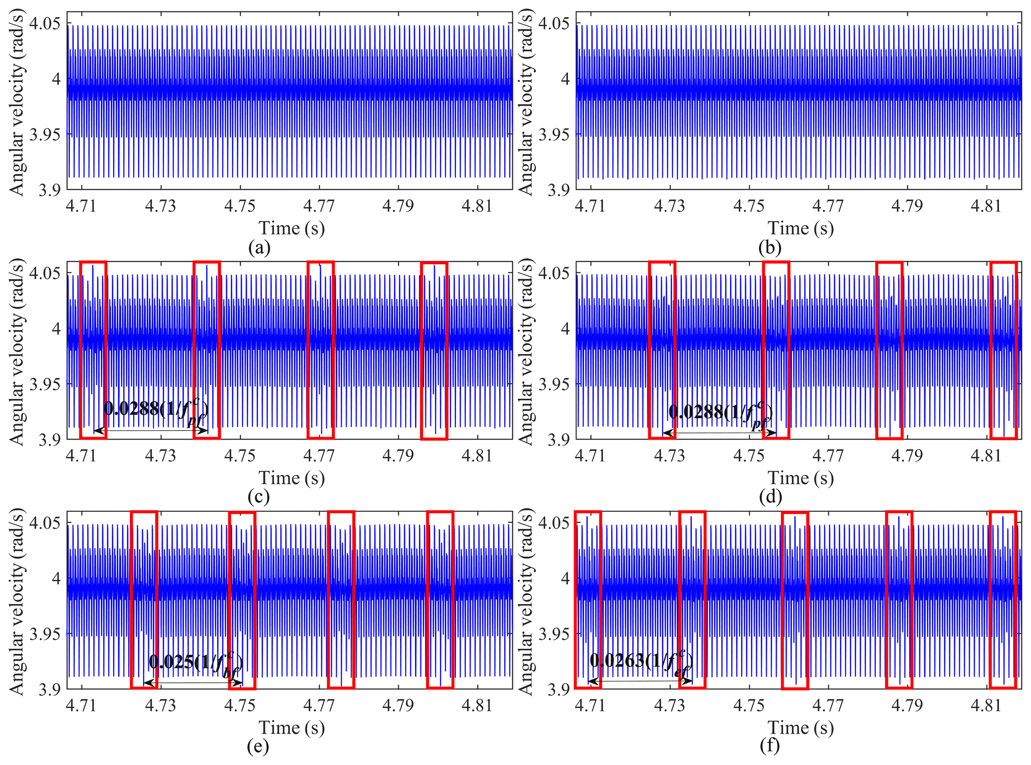
Figure 10Ring gear e angular velocity signals: (a) healthy gear case, (b) failure case I, (c) failure case II, (d) failure case III, (e) failure case IV, and (f) failure case V.
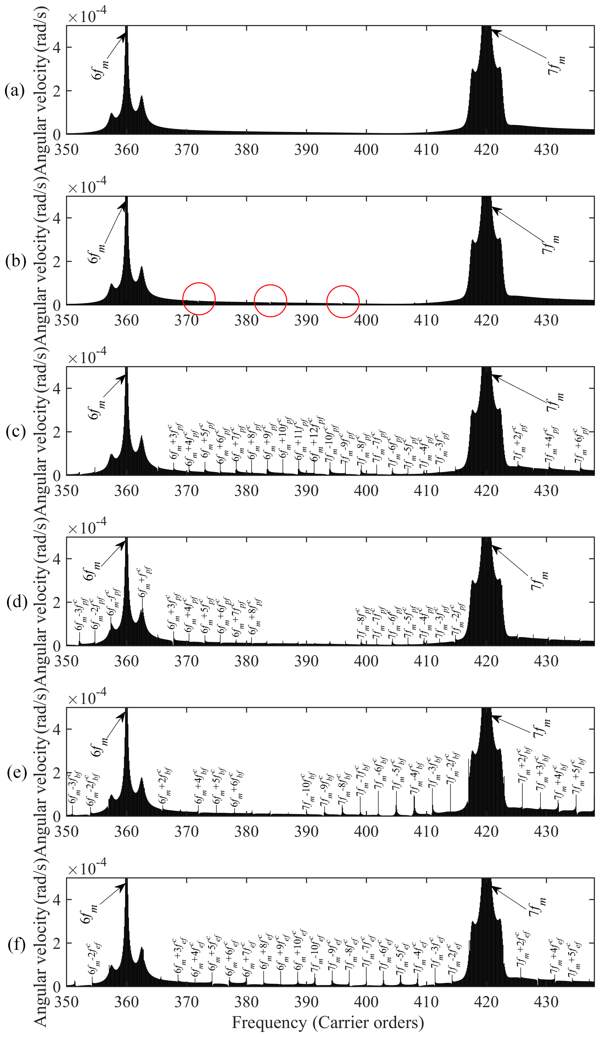
Figure 11Frequency spectrum of ring gear e angular velocity signals: (a) healthy gear case, (b) failure case I, (c) failure case II, (d) failure case III, (e) failure case IV, and (f) failure case V.

Figure 12Cepstrum of ring gear e angular velocity signals: (a) healthy gear case, (b) failure case I, (c) failure case II, (d) failure case III, (e) failure case IV, and (f) failure case V.
As seen in Fig. 10b, the rotational velocity of the ring gear e is less affected by the cracked sun gear. The changes of the frequency component and the inverted frequency component in Figs. 11b and 12b are also not significant compared with the healthy case. It is caused by the high transmission ratio of the 3K-II planetary gear train (105 in this paper) and the massive difference in the moment of inertia and mass between the sun gear and the output ring gear. The relatively small meshing force between the s−p pairs would reduce the impacts of cracked sun gear on the ring gear e.
As illustrated in Fig. 10c–d, for the case with a cracked planet gear, the angular velocity of the ring gear e has many pronounced periodic fluctuations. The time interval between adjacent fluctuations is 0.0288s (), which corresponds to the sharp increment in the amplitude of the inverted frequency domain at 0.0288 s in Fig. 12c–d. Meanwhile, there is also a significant increase in the amplitudes at the location of characteristic frequency (n and k are integers), as displayed in Fig. 11c–d.
When a crack develops on a tooth of ring gear b, the angular velocity of the ring gear e has periodic perturbations with time intervals of 0.025 s (), as depicted in Fig. 10e. Sizable sidebands appear at the positions of frequency (n and k are integers) in Fig. 11e. There is a significant increase in the amplitude of the inverted frequency component at 0.025 s (), as shown in Fig. 12e.
As for the case with a cracked ring gear e, the periodic perturbation interval of the rotational velocity in Fig. 10f is 0.0263 s (). The locations of apparent sidebands change to the frequency (n and k are integers) in Fig. 11f. The position with the largest increment of the inverted frequency component changes to 0.0263 s () in Fig. 12f.
It is seen from the analysis of Figs. 10–12 that the torsional vibration signal can be used to diagnose faults of the 3K-II planetary gear system. In contrast to the transverse synthetic vibration signals in Sect. 3, torsional vibration signals are unaffected by the amplitude modulation due to the carrier's rotation. This makes the fault characteristics in the time domain of a torsional vibration signal more pronounced and the sidebands of fault in the frequency domain easier to identify. However, the torsional vibration signal also has limitations for the fault detection of the 3K-II planetary gear system, like the sun gear local tooth root cracking.
The 3K planetary gear system, as a basic planetary drive structure, is more compact than the 2K-H and has a wider range of transmission ratios. A torsional vibration dynamics model of a 3K-II planetary gear system is developed in this paper. The effect of five crack conditions on the time-varying meshing stiffness is analyzed. A theoretical model that considers the modulation effect due to the rotation of carrier is adopted to obtain the synthetic vibration signals to reveal the housing vibration in the health and tooth root cracking cases. Subsequently, both the feasibility of using the synthetic vibration signals and the torsional vibration signals of the output ring gear as a basis for fault diagnosis of the 3K-II planetary gear system is analyzed by reference to time-domain spectra, frequency spectrum, and cepstrum in the healthy and five cracked-tooth cases. The main conclusions are as follows:
-
The synthetic vibration signal of the planetary housing shows obvious amplitude modulation waves. Furthermore, besides the fault-frequency component, the spectral sidebands also have the carrier rotation frequency component in the frequency domain.
-
The torsion signal is unaffected by the amplitude modulation of the carrier's rotation, making it possible to demonstrate fault diagnostics more clearly in the time and frequency domains.
-
Both the synthetic vibration signal and torsional vibration signal can be used for fault diagnosis of the 3K-II planetary gear system. However, both of them have their limitations, i.e., the synthetic vibration signal is influenced by the modulation of the carrier rotation, which makes the fault characteristics not clear enough, and the spectral sideband composition more is complex, thus making it more complicated to determine the specific fault type; for the torsional vibration signal, in the case of a large transmission ratio, it is difficult to identify the sun gear failures by the angular velocity signal of the output ring gear. In practice, the fault detection of the 3K planetary gearbox should be performed by installing both a sensor on the housing and an angle encoder on the output.
| Notation | |
| ; (kg) | mass of the sun s, planet p, carrier, and rings b and e |
| ; (kg ⋅ m2) | moment of inertia of the sun s, planet p, carrier, and rings b and e |
| N | number of planet gears |
| ; (rad) | working pressure angle of the sun–planet, ring-b–planet, and ring-e–planet gear pairs |
| ; (m) | radial displacement in the x and y directions measured in the rotating coordinate system |
| ; (rad) | angular displacement of the carrier, ring b, ring e, sun, and planets |
| ωc; (rad/s) | rotation speed of the carrier |
| ; (N/m) | bearing radial stiffness of the carrier, ring b, ring e, sun, and planets in the x and y directions |
| ; (N s/m) | bearing radial damping of the carrier, ring b, ring e, sun, and planets in the x and y directions |
| cbu; (N s/rad) | damping of ring b in torsional direction |
| kbu; (N/rad) | stiffness of ring b in torsional direction |
| ; (rad) | circumferential angle of nth planet |
| Te, Ts; (N m) | output torque on the ring e, input torque on the sun s |
| ; (m) | base radius of the sun, planet, ring b, and ring e |
| rc; (m) | radius of the circle through the center of the planet gears |
| ; (m) | relative displacement on the lines of action of nth sun–planet, ring-b–planet, and ring-e–planet gear pairs |
| ; (N/m) | meshing stiffness of the nth sun–planet, ring-b–planet, and ring-e–planet mesh pairs |
| mesh phase difference of the sun s, ring b, and ring e meshes, individually, between each planet gear and the first planet gear | |
| γse1 | mesh phase difference between the sun and ring e meshes of the first planet gear |
| number of teeth of the sun s, planet p, and rings b and e | |
| θm; (rad) | carrier rotation angle within a meshing period |
| fm; (Hz) | gear mesh frequency |
| ; (Hz) | shaft frequency of the carrier, sun s, planet p, and ring e |
| ; (Hz) | fault characteristic frequency of cracked sun s, planet p, and rings b and e |
All the data used to support the findings of this study are included within in the relevant figures and tables in the article.
MS was responsible for the methodology and writing of the draft of the paper, KH and YX contributed to the review and supervision, GH calculated the time-varying meshing stiffness, and ZC checked the article and made suggestions. All authors read and approved the final article.
The contact author has declared that neither they nor their co-authors has any competing interests.
Publisher's note: Copernicus Publications remains neutral with regard to jurisdictional claims in published maps and institutional affiliations.
The authors thank the reviewers for their critical and constructive review of the article.
This research has been supported by the National Natural Science Foundation of China (grant no. 51775156), the National Key R&D Program of China (grant no. 2017YFB0103201), the Natural Science Foundation of Anhui Province of China (grant no. 1908085QE228), the Key Research and Development Project of Anhui Province (grant no. 202004h07020013), and the Fundamental Research Funds for the Central Universities of China (grant no. PA2020GDSK0091).
This paper was edited by Daniel Condurache and reviewed by two anonymous referees.
Addabbo, T., Marco, M. D., Fort, A., Landi, E., Mugnaini, M., Vignoli, V., and Ferretti, G.: Instantaneous Rotation Speed Measurement System Based on Variable Reluctance Sensors for Torsional Vibration Monitoring, IEEE Trans. Instrum. Meas., 68, 2363–2373, https://doi.org/10.1109/TIM.2018.2877808, 2019.
Ambarisha, V. K. and Parker, R. G.: Nonlinear dynamics of planetary gears using analytical and finite element models, J. Sound Vibr., 302, 577–595, https://doi.org/10.1016/j.jsv.2006.11.028, 2007.
Chaari, F., Fakhfakh, T., Hbaieb, R., Louati, J., and Haddar, M.: Influence of manufacturing errors on the dynamic behavior of planetary gears, Int. J. Adv. Manuf. Tech., 27, 738–746, https://doi.org/10.1007/s00170-004-2240-2, 2006.
Chen, K., Huangfu, Y., Ma, H., Xu, Z., Li, X., and Wen, B.: Calculation of mesh stiffness of spur gears considering complex foundation types and crack propagation paths, Mech. Syst. Signal Pr., 130, 273–292, https://doi.org/10.1016/j.ymssp.2019.05.014, 2019.
Feng, Z. and Zuo, M. J.: Fault diagnosis of planetary gearboxes via torsional vibration signal analysis, Mech. Syst. Signal Pr., 36, 401–421, https://doi.org/10.1016/j.ymssp.2012.11.004, 2013.
Hibbeler, R. C.: Dynamics, 3rd Edn., Pearson Prentice Hall, Upper Saddle River, New Jersey, USA, 2004.
Howard, I. M.: An investigation of vibration signal averaging of individual components in an epicyclic gearbox (No. ARL-PROP-R-185), Aeronautical Research Labs Melbourne, Australia, 1991.
Inalpolat, M. and Kahraman, A.: A theoretical and experimental investigation of modulation sidebands of planetary gear sets, J. Sound Vibr., 323, 677–696, https://doi.org/10.1016/j.jsv.2009.01.004, 2009.
Inalpolat, M. and Kahraman, A.: A dynamic model to predict modulation sidebands of a planetary gear set having manufacturing errors, J. Sound Vibr., 329, 371–393, https://doi.org/10.1016/j.jsv.2009.09.022, 2010.
Kahraman, A.: Load sharing characteristics of planetary transmissions, Mech. Mach. Theory, 29, 1151–1165, https://doi.org/10.1016/0094-114X(94)90006-X, 1994.
Kazienko, D. and Chybowski, L.: Instantaneous rotational speed algorithm for locating malfunctions in marine diesel engines, Energies, 13, 1396, https://doi.org/10.3390/en13061396, 2020.
Li, S., Wu, Q., and Zhang, Z.: Bifurcation and chaos analysis of multistage planetary gear train, Nonlinear Dynam., 75, 217–233, https://doi.org/10.1007/s11071-013-1060-z, 2014.
Li, Y., Ding, K., He, G., and Yang, X.: Vibration modulation sidebands mechanisms of equally-spaced planetary gear train with a floating sun gear, Mech. Syst. Signal Pr., 129, 70–90, https://doi.org/10.1016/j.ymssp.2019.04.026, 2019.
Liang, X., Zuo, M. J., and Hoseini, M. R.: Vibration signal modeling of a planetary gear set for tooth crack detection, Eng. Fail. Anal., 48, 185–200, https://doi.org/10.1016/j.engfailanal.2014.11.015, 2015.
Liang, X., Zuo, M. J., and Feng Z.: Dynamic modeling of gearbox faults: A review, Mech. Syst. Signal Pr., 98, 852–876, https://doi.org/10.1016/j.ymssp.2017.05.024, 2018.
Lin, J. and Parker, R. G.: Analytical Characterization of the Unique Properties of Planetary Gear Free Vibration, J. Vib. Acoust., 121, 316–321, https://doi.org/10.1115/1.2893982, 1999.
Liu, J. M., Gu, L. C., and Geng, B. L.: A practical signal processing approach for fault detection of axial piston pumps using instantaneous angular speed, Proc. Inst. Mech. Eng. Pt. C-J. Eng. Mech. Eng. Sci., 234, 3935–3947, https://doi.org/10.1177/0954406220917704, 2020.
Liu, L., Liang, X., and Zuo, M. J.: Vibration signal modeling of a planetary gear set with transmission path effect analysis, Measurement, 85, 20–31, https://doi.org/10.1016/j.measurement.2016.02.006, 2016.
Liu, W., Shuai, Z., Guo, Y., and Wang, D.: Modal properties of a two-stage planetary gear system with sliding friction and elastic continuum ring gear, Mech. Mach. Theory, 135, 251–270, https://doi.org/10.1016/j.mechmachtheory.2019.01.026, 2019.
Liu, X., Yang, Y., and Zhang, J.: Resultant vibration signal model based fault diagnosis of a single stage planetary gear train with an incipient tooth crack on the sun gear, Renew. Energy, 122, 65–79, https://doi.org/10.1016/j.renene.2018.01.072, 2018.
Mark, W. D. and Hines, J. A.: Stationary transducer response to planetary-gear vibration excitation with non-uniform planet loading, Mech. Syst. Signal Pr., 23, 1366–1381, https://doi.org/10.1016/j.ymssp.2008.09.010, 2009.
McFadden, P. D.: A technique for calculating the time domain averages of the vibration of the individual planet gears and the sun gear in an epicyclic gearbox, J. Sound Vibr., 144, 163–172, https://doi.org/10.1016/0022-460X(91)90739-7, 1991.
McFadden, P. D.: Window functions for the calculation of the time domain averages of the vibration of the individual planet gears and sun gear in an epicyclic gearbox, J. Vib. Acoust., 116, 179–187, https://doi.org/10.1115/1.2930410, 1994.
McNames, J.: Fourier series analysis of epicyclic gearbox vibration, J. Vib. Acoust., 124, 150–153, https://doi.org/10.1115/1.1403735, 2002.
Parker, R. G. and Lin, J.: Mesh phasing relationships in planetary and epicyclic gears, J. Mech. Des., 126, 365–370, https://doi.org/10.1115/1.1667892, 2004.
Rao, Z. G.: Planetary gear transmission design, 2nd Edn., Chemical Industry Press, Beijing, China, 2014.
Song, Y., Zhang, J., Zhang, J., Wang, S., and Liu, J.: Inherent Characteristics of 3K-II Spur Planetary Gear Trains, J. Mech. Eng., 45, 23–28, https://doi.org/10.3901/JME.2009.07.023, 2009.
Sun, R. B., Yang, Z. B., Luo, W., Qiao, B. J., and Chen, X. F.: Weighted sparse representation based on failure dynamics simulation for planetary gearbox fault diagnosis, Meas. Sci. Technol., 30, 045008, https://doi.org/10.1088/1361-6501/ab02d8, 2019.
Wang, Y., Tang, B., Qin, Y., and Huang, T.: Rolling bearing fault detection of civil aircraft engine based on adaptive estimation of instantaneous angular speed, IEEE Trans. Ind. Inform., 16, 4938–4948, https://doi.org/10.1109/TII.2019.2949000, 2020.
Wu, S., Zhang, H., Wang, X., Peng, Z., Yang, K., and Zhu, W.: Influence of the backlash generated by tooth accumulated wear on dynamic behavior of compound planetary gear set, Proc. Inst. Mech. Eng. Pt. C-J. Eng. Mech. Eng. Sci., 231, 2025–2041, https://doi.org/10.1177/0954406215627831, 2017.
Xiang, L., Gao, N., and Hu, A.: Dynamic analysis of a planetary gear system with multiple nonlinear parameters, J. Comput. Appl. Math., 327, 325–340, https://doi.org/10.1016/j.cam.2017.06.021, 2018.
Xue, S. and Howard, I.: Torsional vibration signal analysis as a diagnostic tool for planetary gear fault detection, Mech. Syst. Signal Pr., 100, 706–728, https://doi.org/10.1016/j.ymssp.2017.07.038, 2018.
Zeng, Q., Zainab, M., Shao, Y., Gu, F., and Ball, A. D.: Planetary gear fault diagnosis based on instantaneous angular speed analysis, IEEE 2017 23rd International Conference on Automation and Computing (ICAC), IEEE, Huddersfield, UK, https://doi.org/10.23919/IConAC.2017.8081996, 2017.
Zhao, M., Jia, X., Lin, J., Lei, Y., and Lee, J.: Instantaneous speed jitter detection via encoder signal and its application for the diagnosis of planetary gearbox, Mech. Syst. Signal Pr., 98, 16–31, https://doi.org/10.1016/j.ymssp.2017.04.033, 2018.
- Abstract
- Introduction
- The dynamic modeling of 3K-II planetary gear system
- Numerical simulation and transverse synthetic vibration fault signal analysis
- Numerical simulation and torsional vibration fault signal analysis
- Conclusion
- Appendix A: The meaning of the symbols used in this paper
- Data availability
- Author contributions
- Competing interests
- Disclaimer
- Acknowledgements
- Financial support
- Review statement
- References