the Creative Commons Attribution 4.0 License.
the Creative Commons Attribution 4.0 License.
 | 30 Aug 2021
Tooth surface modification of double-helical gears for compensation of shaft deflections
Lan Liu
Qiangyi Ma
Jingyi Gong
Geng Liu
Xiaomei Cao
Based on gear meshing theory, the tooth surface equation with tooth profile modification parameters is deduced, the tooth surfaces of unmodified and modified gears are constructed, the three-dimensional model of unmodified and modified double helical gear-shaft-bearing system is established and then the three-dimensional contact finite element model of double helical gear-shaft-bearing system is established and the load-bearing contact analysis of the tooth surface is carried out. The actual contact state of the tooth surfaces of double helical gears under different shaft stiffness and power transmission paths is investigated, and the influence of tooth modification parameters on the load distribution of the tooth surfaces of double helical gear pairs is studied. The results show that the tooth surface bearing the contact of the herringbone gear system has the phenomenon of partial load due to the supporting deformation, and the unmodified herringbone gear has obvious contact stress concentration. However, the phenomenon of partial load and stress concentration can be effectively improved by gear tooth modification.
- Article
(9261 KB) - Full-text XML
- BibTeX
- EndNote


Large ships usually use wide tooth surface cylindrical gears with large bearing capacity, high transmission efficiency, stable transmission, compact structure and long life, and especially herringbone gears with high coincidence degree and large tooth width are used. For the cylindrical gear with wide tooth surface, the power flow direction and the load will have a great influence on the bearing contact characteristics of the tooth surface.
Gear tooth modification is done to improve the stability of the gear transmission system and reduce vibration and noise by changing the contact state of gears. At present, the research focus is mainly on tooth profile and tooth direction modification. Conry et al. (1973) solved the contact equation of a gear pair and proposed the modification method of spur gear pair and helical gear pair. Lin (1994) compared and analyzed the influence of two different curve modification modes, the quadratic curve and straight line, on gear transmission characteristics. Ohno et al. (1998) applied a three-dimensional finite element method to analyze the contact characteristics of a tooth-profile-modified gear during engagement and compared the contact stress before and after tooth modification. Seol et al. (2000) studied the influence of gear tooth modification on the meshing performance of tooth surface based on numerical analysis and finite element analysis methods and found that gear modification can effectively reduce noise and extend the service life of gears. Tesfahunegn (2010) used the contact finite element method to study the influence of tooth profile modification on bending stress, transfer error and contact stress of spur gear pair. Yang (2018) used KISSsoft to conduct research on the modification design of herringbone gear transmission and optimize the traditional modification design process of herringbone gear. Wang (2019) derived the tooth profile equation of the improved rack tool and established the tooth surface contact analysis (TCA), loaded tooth surface contact analysis (LTCA) and dynamic model of helical gear pair.
The technology of tooth surface bearing contact analysis (Fang, 1998) is to carry out a computer simulation for the gear before a trial production to obtain its working performance under simulated real working conditions. There are many scholars (Gosselin et al., 1995; Litvin et al., 1996; Gosselin et al.,1998; Litvin et al., 2002) who have used the finite element method to analyze the bearing and contact of gear transmission and have obtained the bearing and transmission error curve, the actual coincidence degree, and the changes in the contact and bending stress of the gear transmission. Kristina et al. (2011) established a finite element model of a planar gear and studied the variation law of the maximum contact stress on the tooth surface during a gear engagement period. Gonzalez (2012) used ABAQUS to establish a finite element model that considers the torsion effect of bearing in gear transmission contact and discussed the influence of power flow direction and load size on gear contact. Patil (2014) calculated the contact stress of a helical gear pair under static action by using ANSYS software and studied the variation law of contact stress with the spiral angle and friction coefficient. Francisco (2016) proposed a new method for tooth contact analysis, which solved the contact problem based on the discretization of contact surfaces by reference teeth and geometric adaptive refinement, and calculated the instantaneous contact area of the gear group at each position along the transmission cycle. Lin (2017) used finite element software to carry out load-bearing contact analysis on gears with errors and modifications and studied the error analysis method of the helical gear system coupling transmission. Wang et al. (2018, 2021) proposed an improved time-varying mesh stiffness (TVMS) model of a helical gear pair and a rapid TVMS calculation method, then studied a mesh stiffness model of gear pairs with misalignment and lead crown relief based on the slice theory, and derived the deformation transfer model between the springs in a contact and non-contact state.
The existing load-bearing contact analysis only stays in the traditional gear tooth contact analysis, and there are few studies on the influence of support system deformation, power flow direction and other factors on the load-bearing contact of herringbone gear tooth surface, especially for the modified gear tooth surface. Therefore, on the basis of traditional gear tooth bearing contact analysis, this paper further studies the influence of support system deformation and power flow direction on the bearing contact of the herringbone gear tooth surface, and modifies the gear based on its actual contact state, in order to further reduce the vibration and noise of gear transmission.
2.1 Generation of modified tooth surface
In the process of gear operation, due to the different number of teeth involved in meshing at the same time, the meshing stiffness of gear teeth changes periodically, which leads to the periodic change in the elastic deformation of gear teeth. In addition, the influence of machining error during manufacture and center distance deviation during installation may cause meshing interference and the partial load of gear teeth, resulting in vibration and noise. As an effective way to solve the above problems, gear tooth modification has been widely used in high speed and heavy load gear transmission. Therefore, it is necessary to study the parametric modeling method of a gear pair with tooth modification in order to accurately analyze the influence of gear tooth modification on the dynamic meshing performance of gear.
In this section, based on the space meshing theory, the tooth surface equation of the modified gear is deduced. On this basis, the parametric modeling program of the modified helical gear pair is compiled to automatically generate the accurate tooth surface of the helical gear with tooth profile modification, and then the solid model of the double-helical gear pair with tooth profile modification is established.
First, the two sides of the rack cutter are modified into a parabola shape, and the shape of the tooth profile modification section is obtained according to the coordinate transformation of the gear meshing principle, and then the development process of the helical gear is slightly modified. The tooth modification parameter is introduced to make the tooth surface feed the parabola in the direction of tooth height in the process of the spiral development. It can be imagined that the helical gear is machined by a grinding wheel with tooth profile modification. In the process of the spiral feed, the feed in the direction of tooth depth is distributed according to the parabola.
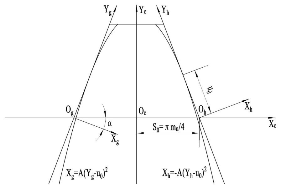
The gear is divided into two tooth surfaces, namely g tooth surface and h tooth surface. As shown in Fig. 1, Sg(ogxgyg) is the modification coordinate system of the left tooth surface, and Sh(ohxhyh) is the modification coordinate system of the right tooth surface. Where α is the pressure angle of indexing circle, S0 is one-quarter of the base segment of the normal plane, A is the quadratic coefficient of the modified parabola, u is the independent variable, and u0 is the axis of symmetry of the modified parabola.
The point on the g-modified tooth surface is represented in the g coordinate system as follows:
The point on the h-modified tooth surface is represented in the h coordinate system as follows:
The coordinate transformation matrices from the tooth surface to rack normal surface includes Mc_g and Mc_h. Mc_g is the transformation matrix of the g tooth surface to rack normal surface, and Mc_h is the transformation matrix of the h tooth surface to rack normal surface.
Sc(oxcyczc) is the normal section coordinate system of a rack, and Sm(oxmymzm) is the rack end coordinate system. The coordinate conversion between Sc and Sm is shown in Fig. 2, where β is the helix angle.
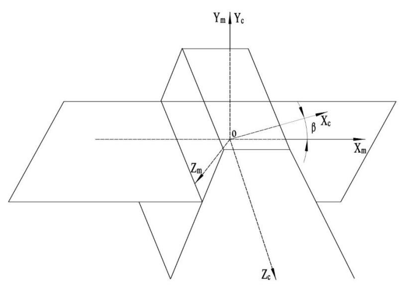
The coordinate transformation matrix between Sc and Sm is as follows:
S1(ox1y1) is a dynamic coordinate system fixed to the end face of the helical gear, and Sn(oxnyn) is a fixed coordinate system connected to the end face of the helical gear. rp is the radius of the gear pitch circle, and φ is the angle of rotation of the coordinate system S1 about the Zn axis.
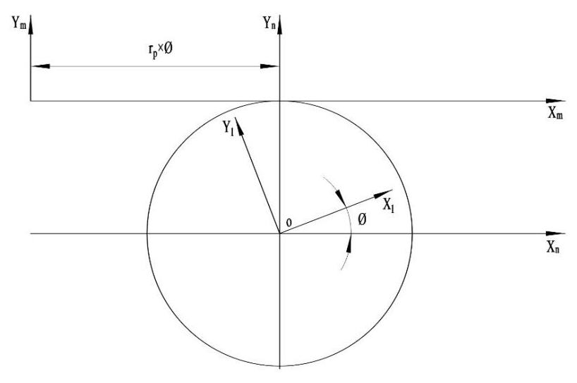
The coordinate transformation matrix between Sm and Sn is as follows:
The coordinate transformation matrix between Sn and S1 is as follows:
S2(ox2y2z2) is the coordinate system moving along the spiral. The coordinate conversion between S1 and S2 is shown in Fig. 4, where and .
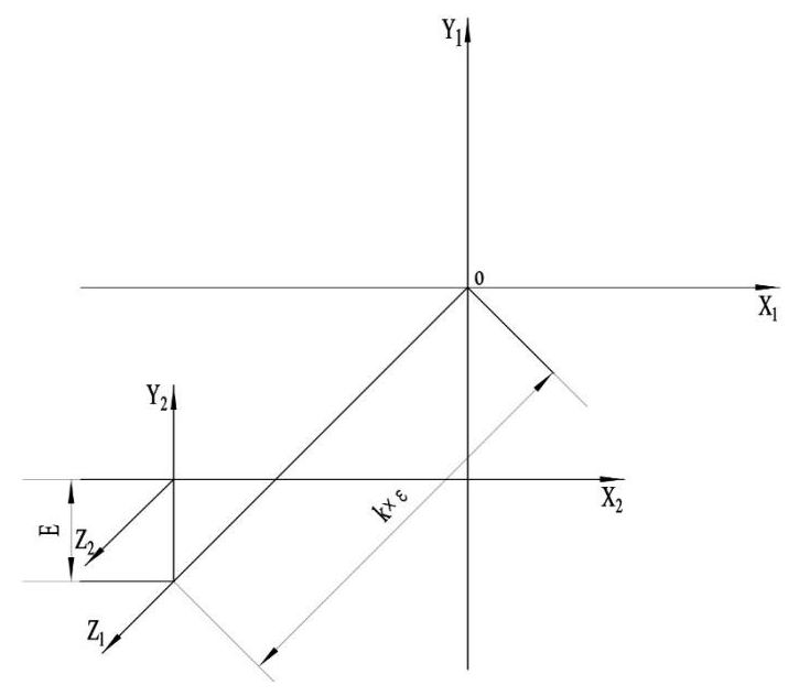
The coordinate transformation matrix between S1 and S2 is as follows:
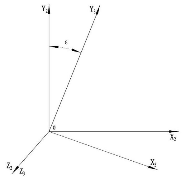
The coordinate transformation matrix between S2 and S3 is as follows:
Finally, the equation of a two-way modified tooth surface is obtained as follows:
To solve the point coordinates of the working tooth surface, there are three unknowns, ε, φ, and u, which need three equations, respectively, as follows:
The derivation of R3 to u is a, the derivation of R3 to ε is b, the derivation of R3 to φ is c, and the meshing equation is a mixed product of the three vectors.
The modified tooth surface point cloud is obtained by programming the calculation, as shown in Fig. 6. The red arrow indicates the direction of tooth width, the white arrow indicates the direction of tooth thickness, and the blue arrow indicates the direction of tooth height.

The point set on the surface is imported into SolidWorks software, and the helical gear tooth surface with tooth modification is created. Then, the tooth surface is stitched to generate the solid, and the accurate three-dimensional solid model of the modified helical gear pair is obtained, as shown in Fig. 7.
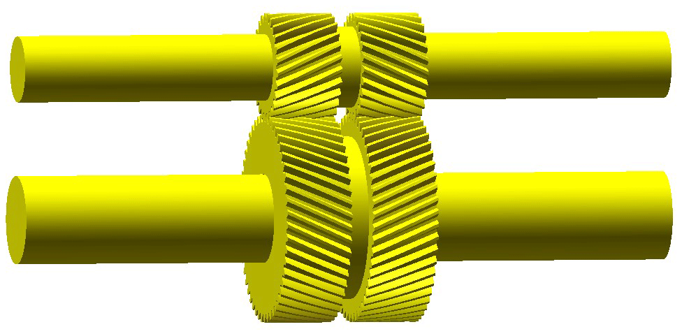
Figure 7The accurate three-dimensional solid model of the modified double-helical gear pair.
2.2 Gear-shaft-bearing system 3D contact finite element model
In the process of gear transmission, with the constant change in the meshing position, the stiffness and bearing position of gear teeth are constantly changing along the tooth direction, and the distribution of the load between teeth is also changing. Accurate solution of load distribution between teeth and load distribution on tooth surface is the basis of gear tooth modification. Most of the existing calculation methods are based on some assumed contact area shape, according to Hertz contact theory, which deviates from the actual contact situation. The finite element method can solve the contact nonlinear problem well, and the instantaneous contact area shape and the pressure distribution of cylindrical gear are very typical contact nonlinear problems, so the finite element software can be used to analyze and calculate the contact state of gear.
In the process of finite element calculation, the quality and quantity of meshing have a great influence on the calculation results and calculation cost. In order to improve the quality of the contact surface mesh and reduce the overall mesh quantity in contact analysis, this paper will cut the gear model. As shown in Fig. 8, the herringbone gear is cut into two helical gears, and each tooth of the helical gear is cut into four parts to facilitate subsequent calculations.
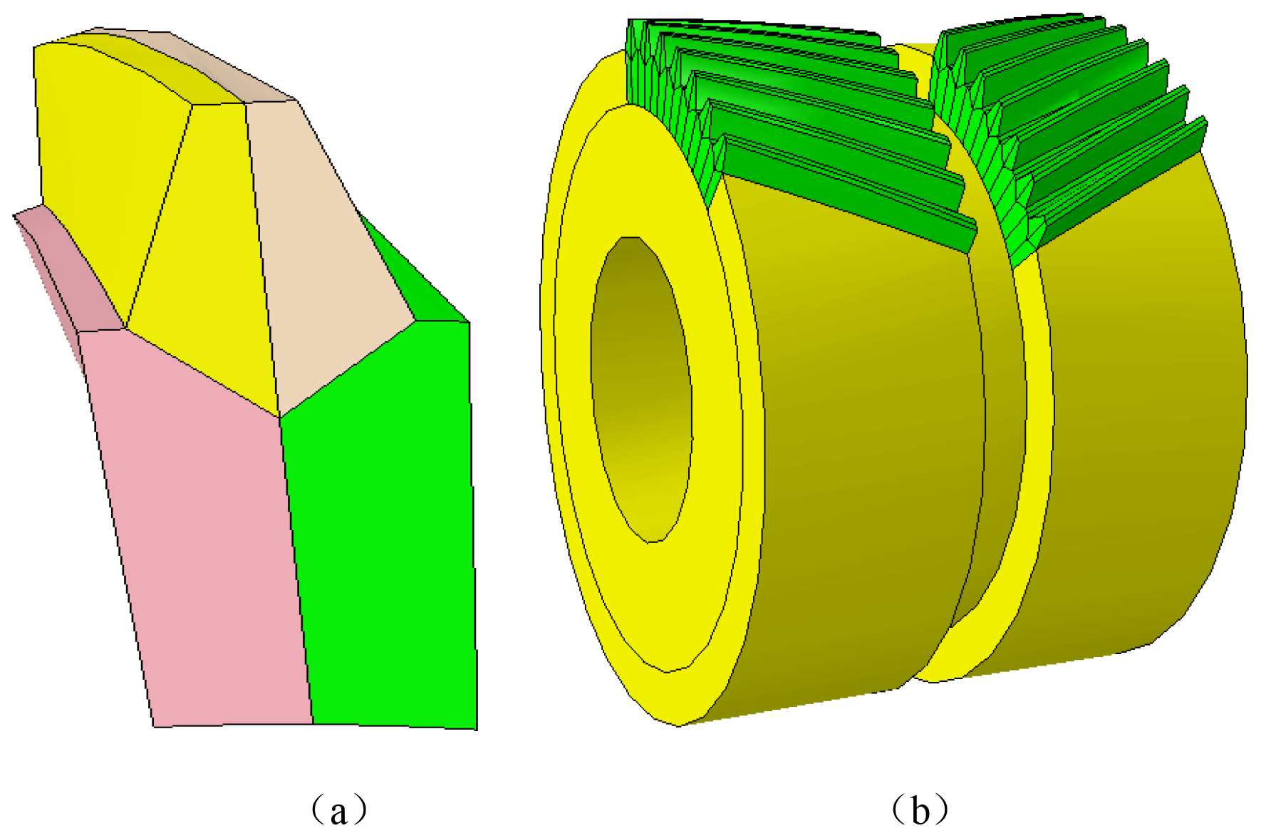
Figure 8Model cutting schematic. (a) Single tooth cutting model. (b) Integral cutting model.
In this paper, the three-dimensional model of the herringbone gear system is imported into the finite element software ABAQUS. The solid segmentation technology is used to divide the model by a hexahedral mesh; the mesh of the contact area of the encrypted tooth surface and the sparse mesh are used in the non-gear contact area. The mesh size of the contact tooth surface is kept at about 50 % of the contact half bandwidth, and the transition mesh size is used to divide the mesh. The mesh along the tooth width direction is 1 mm, and the rest is divided by automatic mesh division. The rationality of this meshing method has been proved in other research (Zhu, 2009; Gonzalez, 2012).
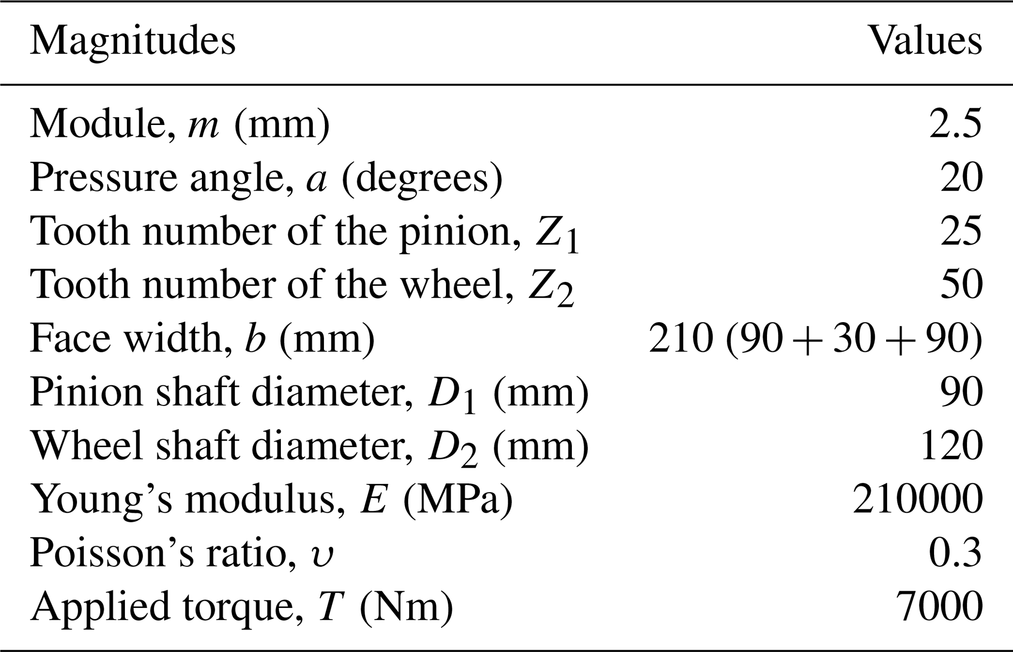
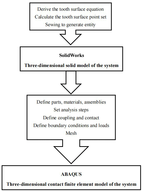
The finite element model of the herringbone gear system established in this paper is shown in Fig. 9, and the design data of the herringbone gear drive represented in Fig. 9 are shown in Table 1. The modeling process is shown in Fig. 10.

Figure 9The finite element models. (a) Meshing of single gear teeth. (b) Meshing of the herringbone gear system.
Table 1Design data of the herringbone gear drive represented in Fig. 9.
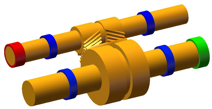
According to the above modeling method, the three-dimensional model of single-stage herringbone gear transmission system is established, as shown in Fig. 11. The blue part is the bearing, the red part is the power input, and the green part is the power output. In order to facilitate the study of the influence of shafting deformation on the gear system, the supporting shafts of the driving wheel and the driven wheel adopt the optical shaft structure, and the driving gear is a gear shaft with a shaft diameter of 45 mm, the supporting shaft diameter of the driven gear is 60 mm, and the length of both shafts is 900 mm. There are four bearings in the two shafts, and the width of the bearing is 35 mm. Then, the other degrees of freedom, except the axial rotation, are constrained at the bearing reference point, the 7000 Nm torque is applied at the reference point of the torque input section of the active shaft, and the fixed constraint is applied at the reference point of the torque output shaft of the driven shaft. The bearing contact state of the herringbone gear tooth surface, considering the supporting deformation, is studied based on this model.
3.1 Influence of the power transmission path
Based on the difference between the power input point and the power output point in the herringbone gear transmission system, the power flow direction of the herringbone gear transmission system is defined as follows: the power input point and the power output point in the herringbone gear transmission system are located on the same side of the gear, and it is called the U-shaped power flow direction; in the herringbone gear transmission system, the power input point and the power output point are located on both sides of the gear and are called the Z-shaped power flow direction. According to the above definition of the power flow direction of herringbone gear transmission, two schematic diagrams of power flow direction are drawn. As shown in Fig. 12, point A is the point of power input, point D is the point of power output, and the path of the power transfer is A-B-C-D.
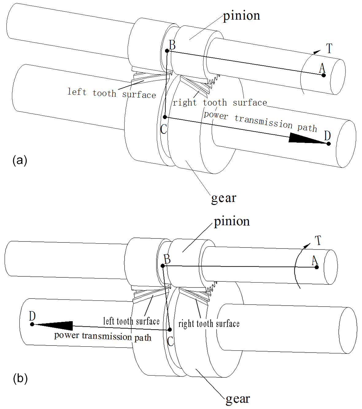
Figure 12Schematic diagram of two different power flows. (a) U-shaped power flow. (b) Z-shaped power flow.
Through the calculation, the tooth surface contact stress cloud diagram of the herringbone gear system with two different power flow directions is as shown in Fig. 13.
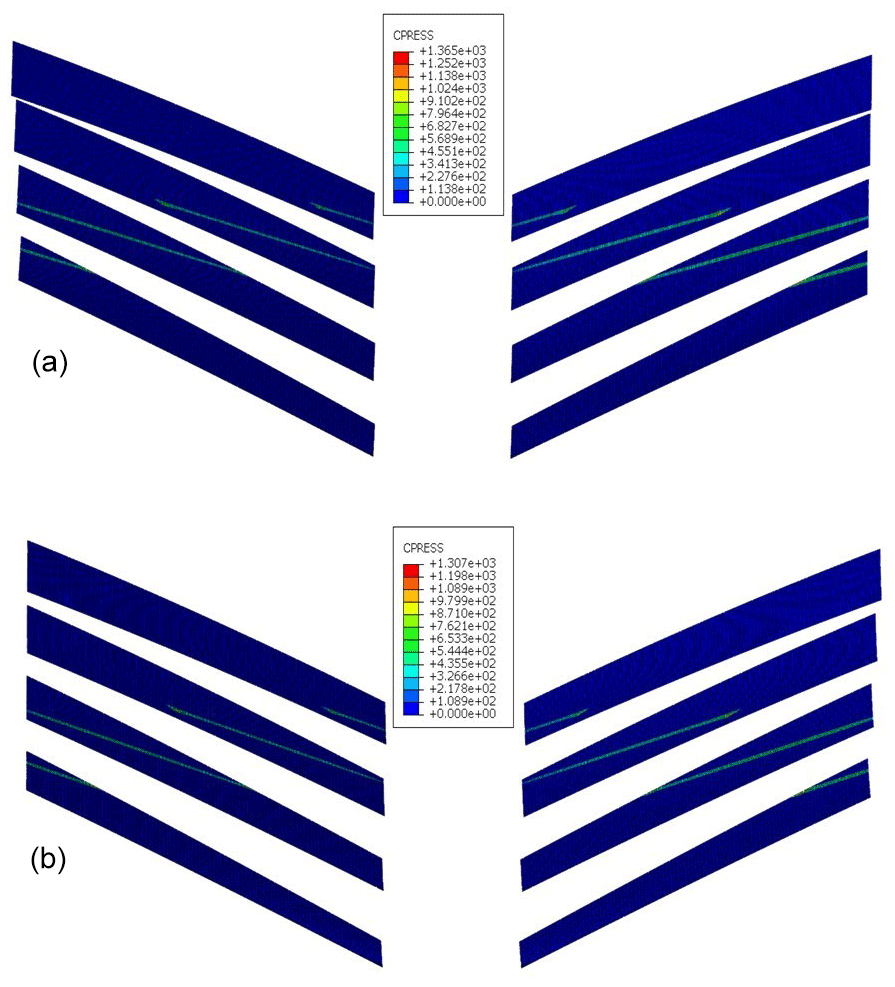
Figure 13Cloud diagram of tooth meshing contact stress with different power flow directions. (a) U-shaped power flow direction tooth meshing contact stress cloud. (b) Z-shaped power flow direction tooth meshing contact stress cloud.
It can be seen from Fig. 13 that the maximum contact stress of the U-shaped power flow is 1365 MPa, and that of the Z-shaped power flow is 1307 MPa. The maximum contact stress of the U-shaped power flow is obviously higher than that of the Z-type power flow.
In order to better study the distribution of contact stress on tooth surface, the contact stress distribution map of the herringbone gear system is drawn on the basis of stress cloud diagram, as shown in Fig. 14.
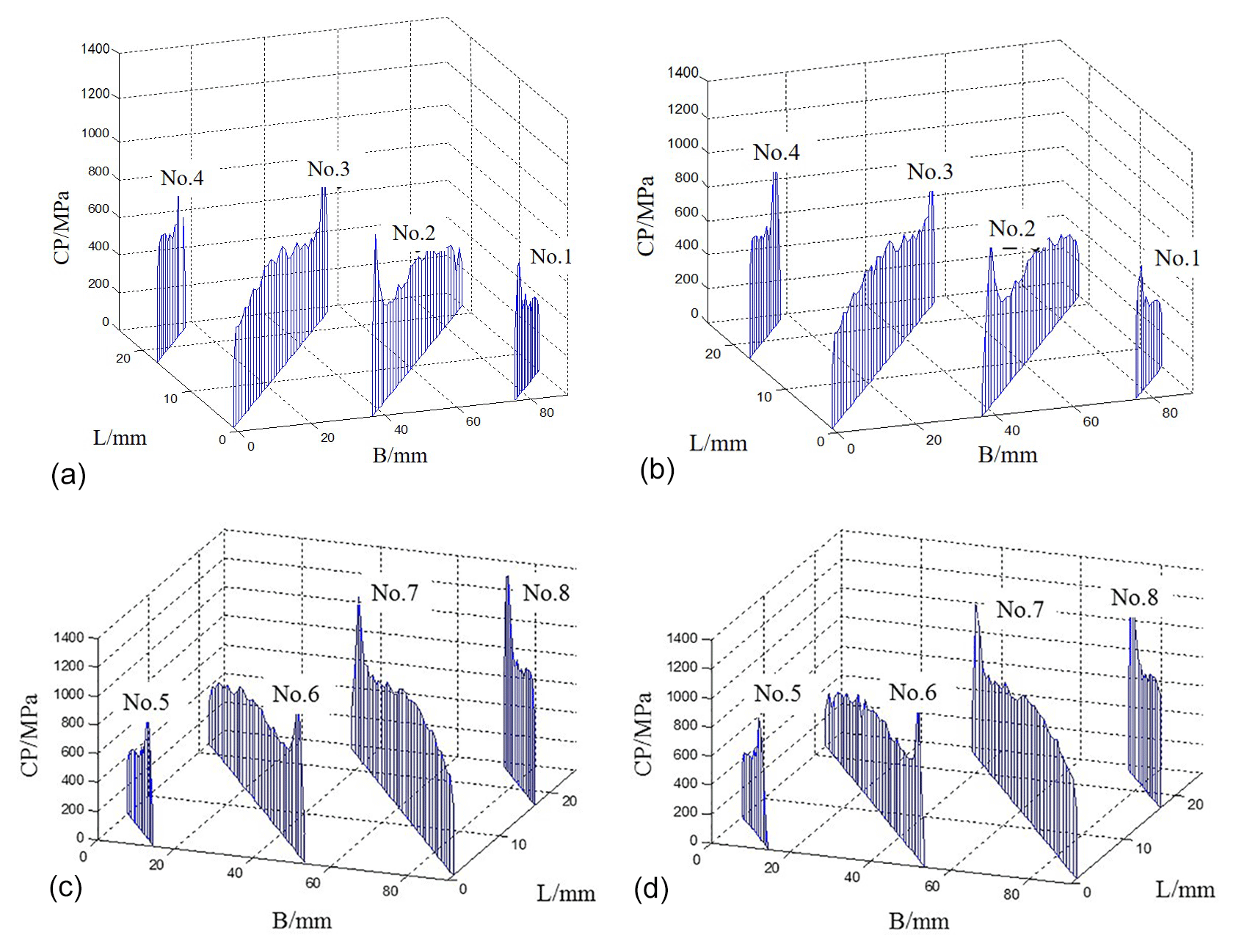
Figure 14Contact stress distribution of the herringbone gear system with two different power flows. (a) The left tooth surface of the U-shaped power flow. (b) The left tooth surface of the Z-shaped power flow. (c) The right tooth surface of the U-shaped power flow. (d) The right tooth surface of the Z-shaped power flow.
In Fig. 14, the contact stress at the tooth vertex of the follower is the largest, followed by the stress at the tooth root, and there is an obvious stress concentration at the tooth root and tooth vertex of the follower. The maximum contact stress of the two different power flows to the left and right tooth surfaces is quite different, and the right tooth, which is the tooth surface close to the power input surface, is larger than the left tooth surface.
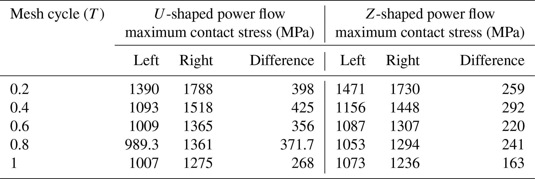
In order to explore the variation law of contact stress value of different power flow direction in one meshing cycle, this paper calculates the maximum contact stress of two tooth surfaces of each power flow direction and the difference in left and right tooth surfaces. The contact stresses of different power flow directions on the tooth surface are enumerated, as shown in Table 2.
Table 2Contact stress of left and right tooth surfaces with different power flow directions.
In order to study the change in the maximum contact stress of the gear in one meshing cycle, the difference curves of the maximum contact stress on the left and right tooth surfaces with two different power flows are drawn, as shown in Fig. 15.
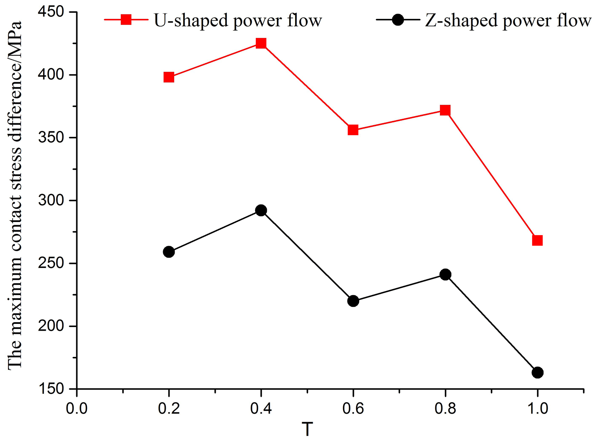
Figure 15The maximum contact stress difference between the left and right tooth surfaces of two kinds of power flow.
It can be clearly seen from Table 2 and Fig. 15 that there is a partial load on the tooth surface of the herringbone gear system with the U-shaped and the Z-shaped power flow, and the partial load of the U-shaped power flow is more serious than that of the Z-shaped power flow.
3.2 Influence of the shaft stiffness
As an important supporting component of the gear transmission system, the stiffness change in the gear-bearing shaft has a great influence on the bearing contact state of the tooth surface of the whole system. In order to study the specific influence of the stiffness of the supporting shaft segment on the contact state of the tooth surface, the bearing contact state of the herringbone gear system with five different stiffness is calculated by changing the elastic modulus of the shaft section to change the stiffness of the shaft section. The parameters of the gear model are shown in Table 1; the power flow direction is the Z-shaped power flow direction, and the elastic moduli of five different shaft segments are shown in Table 3.
Table 3The five different shaft stiffness of a herringbone gear system.

In order to clearly see the contact stress distribution on each contact line, this paper draws the contact stress distribution map of the left and right tooth surfaces with different shaft stiffness according to the contact stress value.
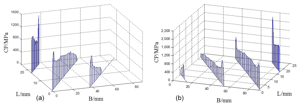
Figure 16Contact stress distribution of the tooth surface with the stiffness of the no. 1 shaft section. (a) Left tooth surface. (b) Right tooth surface.
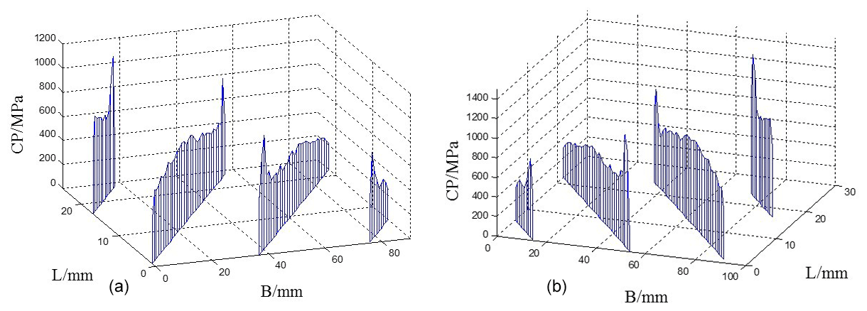
Figure 17Contact stress distribution of the tooth surface with the stiffness of the no. 2 shaft section. (a) Left tooth surface. (b) Right tooth surface.
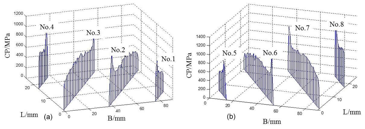
Figure 18Contact stress distribution of the tooth surface with the stiffness of the no. 3 shaft section. (a) Left tooth surface. (b) Right tooth surface.
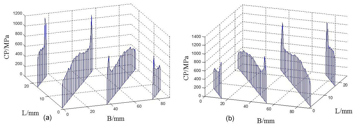
Figure 19Contact stress distribution of the tooth surface with the stiffness of the no. 4 shaft section. (a) Left tooth surface. (b) Right tooth surface.
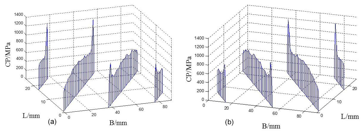
Figure 20Contact stress distribution of the tooth surface with the stiffness of the no. 5 shaft section. (a) Left tooth surface. (b) Right tooth surface.
Through a comprehensive comparison of the contact stress distribution maps of the tooth surfaces with five different shaft stiffness, it can be concluded that, with the increase in the shaft stiffness, the maximum contact stress of the tooth surface decreases, and the difference between the left and right tooth surfaces gradually decreases. When the stiffness of the shaft section is large, the phenomenon of partial load on the left and right tooth surface disappears. When the stiffness of the shaft section is small, the supporting deformation of the shaft section is larger, and the stress concentration mainly appears at the tooth root of the driven wheel.
3.3 Influence of modification parameters
In this section, the influence of different tooth profile modifications on tooth surface bearing contact is calculated in the finite element analysis software in order to explore the best modification amount of herringbone gear system.
The gear teeth will have certain elastic deformation due to the action of the load, including the contact deformation, bending deformation, shear deformation and tooth root deformation. The deformation is related to the load on the gear teeth and the meshing stiffness of the gear teeth, which can be approximated by the following Eq. (15):
δa is the elastic deformation of tooth profile (micrometer; hereafter µm), Wt is the load per tooth width (Newtons per millimeter; hereafter N/mm), and cγ is the meshing stiffness per tooth width (Newtons per millimeter micrometer; hereafter N/mm µm).
According to the above equation, the tooth profile deformation of the model in this chapter is calculated to be 28.5 µm, which is the theoretical tooth profile modification.
According to the coordinate comparison of tooth surface before and after modification, the tooth profile modification curve is drawn. On the basis of the amount of theoretical practice, two cases which are larger than the amount of theoretical modification and smaller than the amount of theoretical modification are calculated respectively, and the curves of three different tooth profile modifications are shown in the Fig. 21.
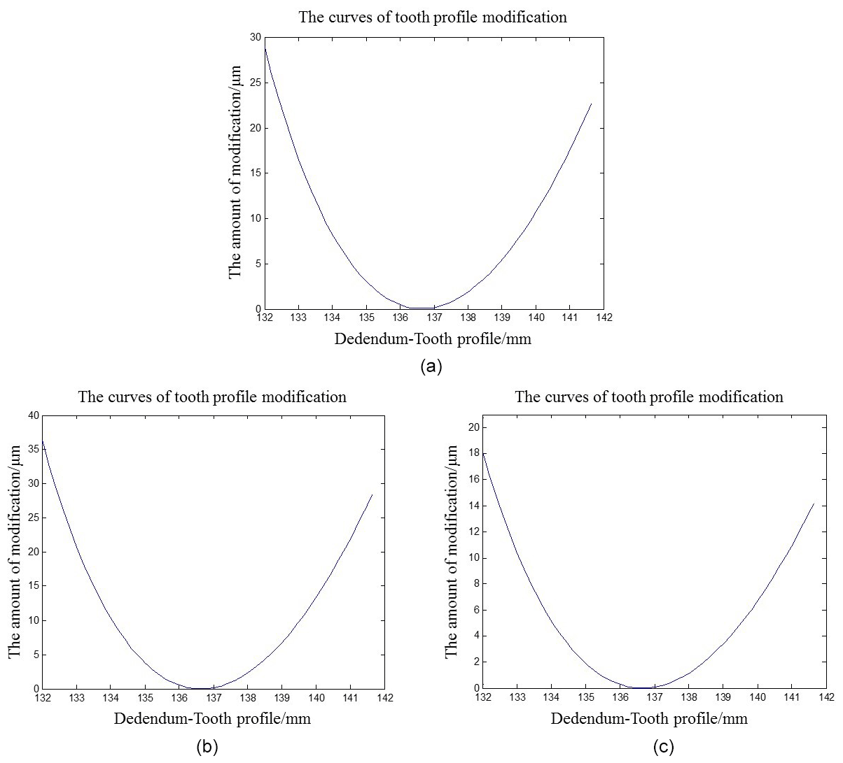
Figure 21The three different tooth profile modification curves. (a) Maximum amount of theoretical modification at 28.5 µm. (b) Maximum amount of modification at 37 µm. (c) Maximum amount of modification at 18.5 µm.
The maximum amount of modification is designed according to the calculated tooth profile deformation, and the modified model is calculated; then, the contact stress cloud diagram of the modified tooth surface is obtained, as shown in Fig. 22.
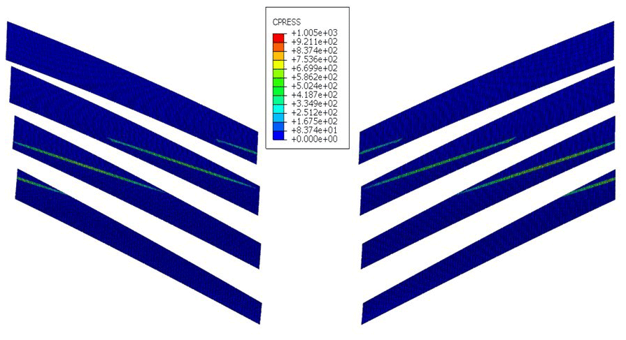
It can be seen from Figs. 13 and 22 that the contact stress distribution of the left and right tooth surfaces after tooth profile modification is still symmetrical, and the maximum contact stress is obviously lower than that without profile modification.
The different power flow direction will make the partial load degree of the tooth surface load contact of herringbone gear system different. Considering this difference, the influence of different tooth profile modifications on the tooth surface load contact with the different power flow direction is studied. According to the calculation results, the contact stress distribution of tooth surface under the action of different modification values of two different power directions are drawn in Figs. 23 and 24.

Figure 23Contact stress distribution of the right tooth surface with three different modification values of the Z-shaped power flow. (a) Maximum amount of modification at 37 µm. (b) Maximum amount of modification at 28.5 µm. (c) Maximum amount of modification at 18.5 µm.
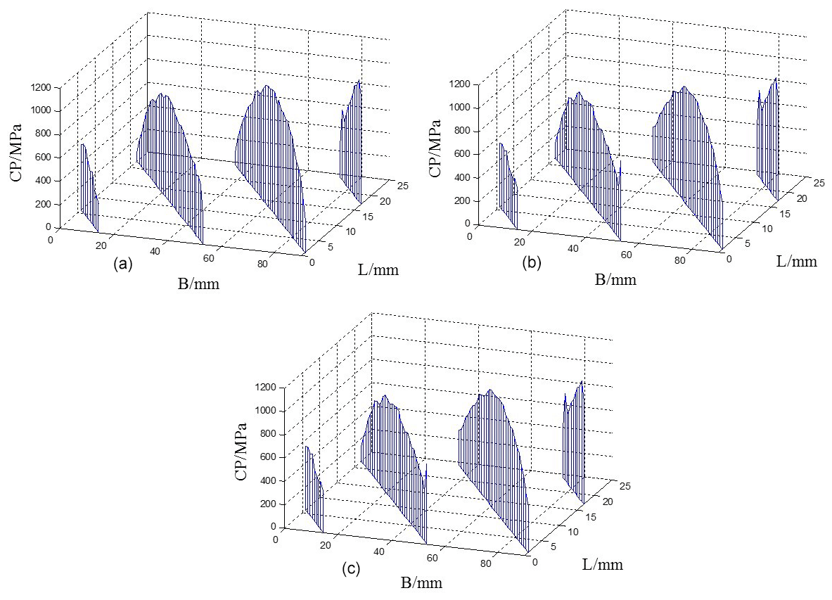
Figure 24Contact stress distribution of the right tooth surface with three different modification values of the U-shaped power flow. (a) Maximum amount of modification at 37 µm. (b) Maximum amount of modification at 28.5 µm. (c) maximum amount of modification at 18.5 µm.
As can be seen from Fig. 23, when the maximum amount of modification is more than 30 % of the theoretical amount of modification, the stress concentration at the root and top of the tooth can be completely eliminated, and the contact stress distribution on the tooth surface is parabolic; when the maximum amount of modification is less than 35 % of the theoretical amount, the stress concentration phenomenon still exists, but the maximum contact stress of the whole tooth surface decreases, and the contact stress distribution of the tooth surface tends to be rectangular. Comparing Figs. 23 and 24, we can see that, when the maximum tooth profile modification is greater than or equal to the theoretical modification, the tooth surface contact stress distribution of the two different power flow directions is the same, but when the maximum modification amount is less than the theoretical modification amount, then the tooth surface stress distribution of the U-type power flow direction is more uniform than that of the Z-type power flow direction.
Through the research, this paper finds that the stiffness of different shaft segments has a great influence on the load-bearing contact state of the tooth surface, so the influence of different tooth profile modification on the tooth surface contact state, according to the stiffness of different shaft segments, will be further analyzed and then determine the appropriate amount of tooth profile modification for different shaft stiffness. In order to complete the above research, aiming at the stiffness of shaft nos. 2 and 4, which are shown in Table 3, the tooth surface contact stress distributions corresponding to three different tooth profile modifications are calculated, and the tooth surface contact stress distributions of different shaft stiffness under different tooth profile modifications are drawn, as shown in Figs. 25 and 26.
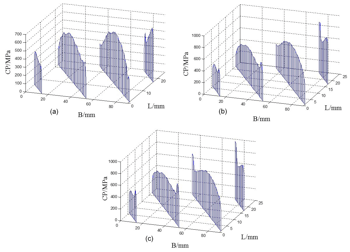
Figure 25Contact stress distribution of the right tooth surface with the three different modifications of the no. 2 shaft section stiffness. (a) Maximum amount of modification at 37 µm. (b) Maximum amount of modification at 28.5 µm. (c) Maximum amount of modification at 18.5 µm.
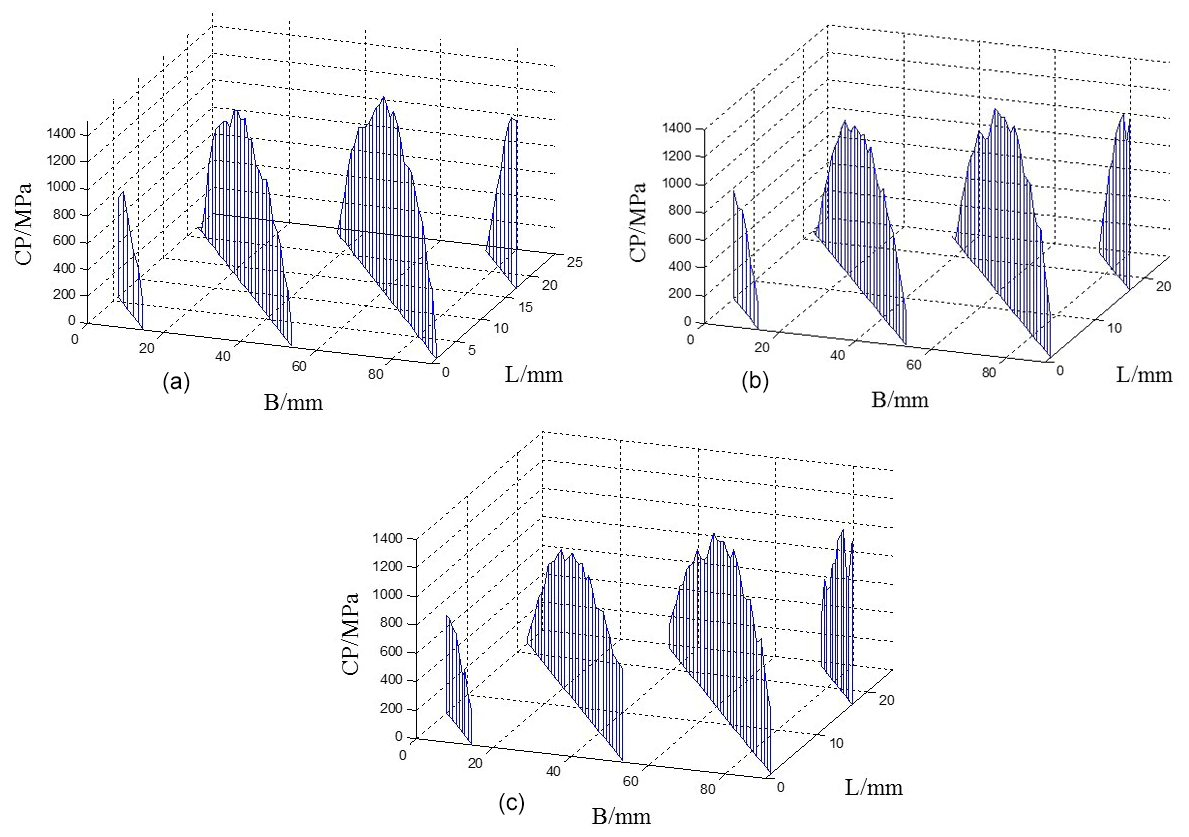
Figure 26Contact stress distribution of the right tooth surface with the three different modification of the no. 4 shaft section stiffness. (a) Maximum amount of modification at 37 µm. (b) Maximum amount of modification at 28.5 µm. (c) Maximum amount of modification at 18.5 µm.
It can be seen from Fig. 25 that when the maximum amount of modification is equal to or less than the theoretical amount of modification, the stress concentration at the root and top of the tooth still exists, and the smaller the amount of modifications, the more obvious the stress concentration at the root and top of the tooth is; when the amount of modification is larger, the contact stress of the tooth surface is also relatively small. In Fig. 26, three different tooth profile modifications have little effect on the contact stress distribution of the tooth surface, and the stress concentration of the tooth root and tooth top disappears.
In this paper, based on the study of the contact state of the herringbone gear pair tooth surface, the herringbone gear system model considering the supporting deformation is established, and the bearing contact state of the tooth surface is studied. In view of the gear contact problem found in the research, the herringbone gear is designed, and the maximum amount of tooth profile modification is determined according to the deformation of the tooth profile direction. The conclusions of the study are summarized as follows.
Due to the supporting deformation, there is a serious partial load on the left and right tooth surface of the herringbone gear, and the contact stress of the tooth surface near the torque input is obviously larger than that near the free end. Tooth profile modification can eliminate the stress concentration at the root and top of the tooth, reduce the maximum contact stress on the tooth surface, and improve the partial load on the left and right tooth surface of the herringbone gear system to a certain extent.
The tooth surface load contact of the herringbone gear system with two kinds of power flow direction has the phenomenon of partial load, but the partial load degree of the U-type power flow direction is more serious than that of the Z-type power flow direction. For two kinds of herringbone gear systems with different power flows, the unified tooth profile modification can be adopted, but the tooth profile modification should be larger than the theoretical modification.
The greater the stiffness of the shaft section is, the more the load-bearing contact of the tooth surface tends to be non-axial, and the lighter the partial load of the left and right tooth surface is, the closer it is to the load-bearing contact state of the herringbone gear pair. In the future design, when the stiffness of the shaft section is larger, the amount of tooth profile modification can be smaller, but when the stiffness of the shaft section is small, the amount of tooth profile modification should be larger.
All the code used in this paper can be obtained upon request to the corresponding author.
All the data used in this paper can be obtained upon request to the corresponding author.
LL, QM, and JG conceived of the presented idea. LL established an overall paper research framework. QM conducted data calculation for the overall paper. JG participated in the establishment of the model. GL supervised the findings of this work. XC collected and provided the model data. All the authors discussed the results and contributed to the final paper.
The authors declare that they have no conflict of interest.
Publisher's note: Copernicus Publications remains neutral with regard to jurisdictional claims in published maps and institutional affiliations.
The authors would like to thank anonymous reviewers for their valuable comments and suggestions that enabled us to revise the paper.
This research has been supported by the Ministry of Science and Technology of the People's Republic of China, National Key Technologies Research and Development Program (grant no. 2018YFB2001501) and the National Natural Science Foundation of China, Key Program (grant no. 51535009).
This paper was edited by Hui Ma and reviewed by two anonymous referees.
Conry, T. F. and Seireg, A.: A Mathematical Programming Technique for the Evaluation of Lo-ad Distribution and Optimal Modifications for Gear Systems, J. Eng. Indust., 95, 1115–1122, https://doi.org/10.1115/1.3438259, 1973.
Fang, Z. D.: Model and Approach for Loaded Tooth Contact Analysis (LTCA) of Gear Drives, J. Mech. Trans., 22, 2–4, https://doi.org/10.16578/j.issn.1004.2539.1998.02.001, 1998.
Francisco, S. M. and Jose, L. I.: Numerical tooth contact analysis of gear transmissions t-hrough the discretization and adaptive refinement of the contact surfaces, Mech. Mach. Theory, 101, 75–94, https://doi.org/10.1016/j.mechmachtheory.2016.03.009, 2016.
Gonzalez, P. I., Roda, C. V., Fuentes, A., Sanchez, M. F., and Iserte, J. L.: A Finite Element Model for Consideration of the Torsional Effect on the Bearing Contact of Gear Drives, J. Mech. Design, 134, 1281–1292, https://doi.org/10.1115/1.4006831, 2012.
Gosselin, C., Cloutier, L., and Nguyen, Q. D.: A general formulation for the calculation of the load sharing and transmission error under load of spiral bevel and hypoid gears, Mech. Mach. Theory, 30, 433–450, https://doi.org/10.1016/0094-114X(94)00049-Q, 1995.
Gosselin, C., Gagnon, P., and Cloutier, L.: Accurate Tooth Stiffness of Spiral Bevel Gear Teeth by the Finite Strip Method, J. Mech. Design, 120, 599–605, https://doi.org/10.1115/1.2829321, 1998.
Kristina, M. and Marina, F.: Contact stresses in gear teeth due to tip relief profile modification, Eng. Rev., 31, 19–26, 2011.
Lin, H. H., Oswald, F. B., and Townsend, D. P.: Dynamic loading of spur gears with linear or parabolic tooth profile modifications, Mechan. Mach. Theory, 29, 1115–1129, https://doi.org/10.1016/0094-114X(94)90003-5, 1994.
Lin, T. J. and He, Z. Y.: Analytical method for coupled transmission error of helical gear system with machining errors, assembly errors and tooth modifications, Mech. Syst. Signal Process., 91, 167–182, https://doi.org/10.1016/j.ymssp.2017.01.005, 2017.
Litvin, F. L., Chen, J. S., Lu, J., and Handschuh, R. F.: Application of Finite Element Analysi-s for Determination of Load Share, Real Contact Ratio, Precision of Motion, and Stress Analysis, J. Mech. Design, 118, 561–567, https://doi.org/10.1115/1.2826929, 1996.
Litvin, F. L., Fuentes, A., Zanzi, C., and Pontiggia, M.: Face-gear drive with spur involute pini-on: geometry, generation by a worm, stress analysis, Comput. Method. Appl. M., 191, 2785–2813, https://doi.org/10.1016/S0045-7825(02)00215-3, 2002.
Ohno, K. and Tanaka, N.: Contact Stress Analysis for Helical Gear with 3-Dimensional Finite Element Method, The Profile Correction Amount to Reduce the PV Factor of Helical Gear Tee-th, Trans. Jpn. Soc. Mech. Eng., 64, 4821–4826, https://doi.org/10.1299/kikaic.64.4821, 1998.
Patil, S. S., Karuppanan, S., Atanasovska, I., and Wahab, A. A.: Contact stress analysis of heli-cal gear pairs, including frictional coefficients, International J. Mech. Sci., 85, 205–211, https://doi.org/10.1016/j.ijmecsci.2014.05.013, 2014.
Seol, I. and Chung S.: Simulation of meshing for the spur gear drive with modified tooth sur-faces, KSME Int. J., 14, 490–498, https://doi.org/10.1007/BF03185651, 2000.
Tesfahunegn, Y. A., Rosa, F., and Gorla, C.: The effects of the shape of tooth profile modifica-tions on the transmission error, bending, and contact stress of spur gears, P. I. Mech. Eng. Pt. C, 224, 1749–1758, https://doi.org/10.1243/09544062JMES1844, 2010.
Wang, C.: Optimization of Tooth Profile Modification Based on Dynamic Characteristics of Hel-ical Gear Pair, Iranian Journal of Science and Technology, Trans. Mech. Eng., 43, 631–639, https://doi.org/10.1007/s40997-018-0184-7, 2019.
Wang, Q. B., Zhao, B., Fu, Y., Kong, X. G., and Ma, H.: An improved time-varying mesh stiffness model for helical gear pairs considering axial mesh force component, Mech. Syst.Signal Process., 106, 413–429, https://doi.org/10.1016/j.ymssp.2018.01.012, 2018.
Wang, Q. B., Xu, K., Huai, T. S., Ma, H., and Wang, K.: A mesh stiffness method using slice coupling for spur gear pairs with misalignment and lead crown relief, Appl. Mathemat. Model., 90, 845–861, https://doi.org/10.1016/J.APM.2020.08.046, 2021.
Yang, S., Di, H., Tang, J., and Wan, G.: Research of the Design of Double Helical Gear Mod-ification based on KISSsoft Software, J. Mech. Trans., 42, 1–6, https://doi.org/10.16578/j.issn.1004.2539.2018.01.001, 2018.
Zhu, Z. H.: Application of ABAQUS software in solution of Hertz's contact problem[J], Machinery, 36, 11–13, 2009.