the Creative Commons Attribution 4.0 License.
the Creative Commons Attribution 4.0 License.
 | 13 Aug 2021
Research on low-speed characteristics of differential double-drive feed system
Xianying Feng
Hongtao Yang
Huawei Jin
It is difficult to achieve high-precision control due to frictional nonlinearity by traditional linear control methodology for the classical drive feed system at low speed. Here, the double-drive differential feed system is proposed to reduce the influence of the nonlinear friction at the ball screw pair of a linear feed system operating at low speed. The dynamic models and the LuGre friction models of the classical drive feed system and the double-drive differential feed system are established, respectively. Based on these, the simulation models of the classical drive feed system and the double-drive differential feed system are established in MATLAB to study the critical creeping velocity of the table. Compared with the classical drive feed system, a lower stable velocity can be obtained for the table with the double-drive differential feed system, because the speed of both motors in the double-drive differential feed system is higher than the critical creeping speed of the classical drive feed system screw motor, thereby overcoming the influence of the Stribeck effect and avoiding the frictional nonlinearity at low speed.
- Article
(4139 KB) - Full-text XML
- BibTeX
- EndNote


One of the key technology bottlenecks of ultra-precision machining is how to make the micro-displacement of the tool or workpiece accurate, stable and reliable in the process of machining. The precision drive feed system plays an important role in precision operation such as precision measurement and precision machining (Yung et al., 2003; Kong et al., 2015) However, for the classical drive feed system (CDFS), based on the servo motor and the rolling contact component, it is difficult to achieve precise and uniform motion of the displacement feed because of its low speed and nonlinear crawling problem, which can not meet the urgent needs of ultra-precision machining (Kumar et al., 2012; Chen et al., 2004; Armstrong et al., 1994).
In order to reduce the influence of friction on the feed system, a lot of research has been done on friction modeling and friction compensation (Michael et al., 2004; Shi et al., 2003; Rafael et al., 2019; Naijing et al., 2018; Kai et al., 2018). The LuGre model, put forward by Canudas et al. (1995), includes pre-sliding friction and sliding friction. This model can describe the main characteristics of dynamic friction, including the Stribeck effect, hysteresis, spring characteristics of static friction and changing sliding friction. Liu et al. (2015) proposed a comprehensive identification method for the structure and friction parameters of the ball screw feed system. The distributed component friction model of a feed drive system, which was proposed by Lee et al. (2015), is composed of models of individual feed drive components such as ball screw and linear motion (LM) guide including their friction behaviors. Hongbiao et al. (2009) equated the friction at the linear guide of the ball screw feed system to the rolling friction at the ball screw pair, established a LuGre friction model, and identified the static and dynamic friction parameters of the LuGre friction model. To reduce the influence of friction on the feed system, Lee et al. (2008) proposed a new dual-speed controller for the compensation of nonlinear friction torque, which has an outer speed controller and an inner friction torque compensator. Besides, Han et al. (2012) proposed an adaptive dynamic surface control scheme combined with sliding mode control to compensate for friction and backlash nonlinearities of ball-screw-driven systems.
However, the friction compensation method, based on the friction model proposed above, cannot avoid the nonlinear friction disturbance when the table is running at low speed for the ball screw feed system. In this paper, a novel differential double-drive feed system (DDFS) is developed to minimize the influence of the nonlinear friction at the ball screw pair of a linear feed system operating at low speed. In the DDFS, the screw and the nut are both driven by permanent magnet synchronous motors (PMSMs) that rotate in the same direction at nearly equal high speed, which are superimposed by the ball screw pair to obtain low-velocity linear motion of the table. In this way, it ensures that the driven table travels at low velocity while the two motors are allowed to rotate at high speed. Compared with the CDFS, the DDFS can reduce the influence of the nonlinear friction at the ball screw pair, thereby improving the speed smoothness at low-speed operation.
The remainder of this paper is arranged as follows. The structure of the DDFS is proposed in Sect. 2. The dynamic modeling of the DDFS is described in Sect. 3. The friction model and friction parameter identification are described in Sect. 4. The simulation and analysis of the critical creeping speed of the DDFS are presented in Sect. 5. The experimental results to validate the effectiveness of the proposed method are in Sect. 6. The paper is concluded in Sect. 7.
In the CDFS, the screw shaft is driven by a servo motor through a coupling, and the rotary motion of the motor is converted into the linear motion of the table. The schematic diagram for the structure of the DDFS based on the nut driven ball screw pair is illustrated in Fig. 1.
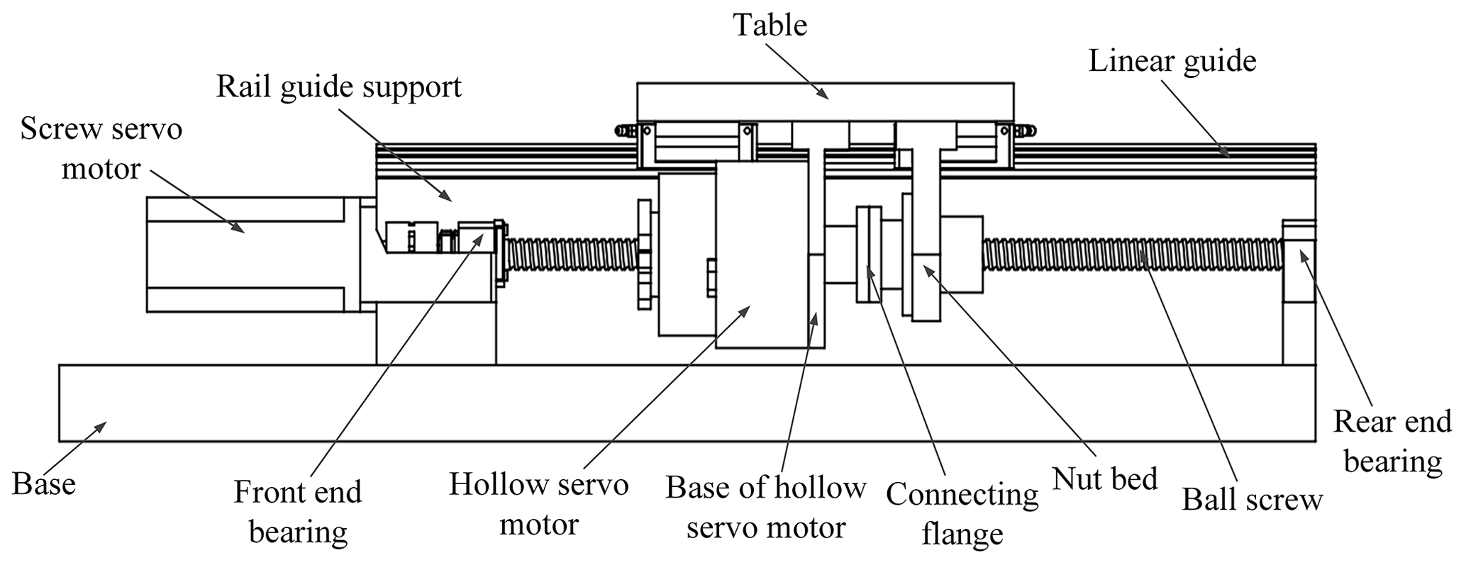
In the DDFS, the screw shaft and screw nut, both driven by PMSMs, rotate in the same direction at high speed and are superimposed though the ball screw pair to obtain low-velocity of the table. This design ensures that the driven table travels at low velocity with the two motors rotating at high speed. The low velocity of the table is obtained, and the crawling zone for the motors at low speed is avoided by superimposing two PMSM rotating speeds at high speed by the ball screw pair (Du et al., 2018; Wang et al., 2019). In the DDFS, when the hollow servo motor does not rotate, the DDFS changes to the CDFS.
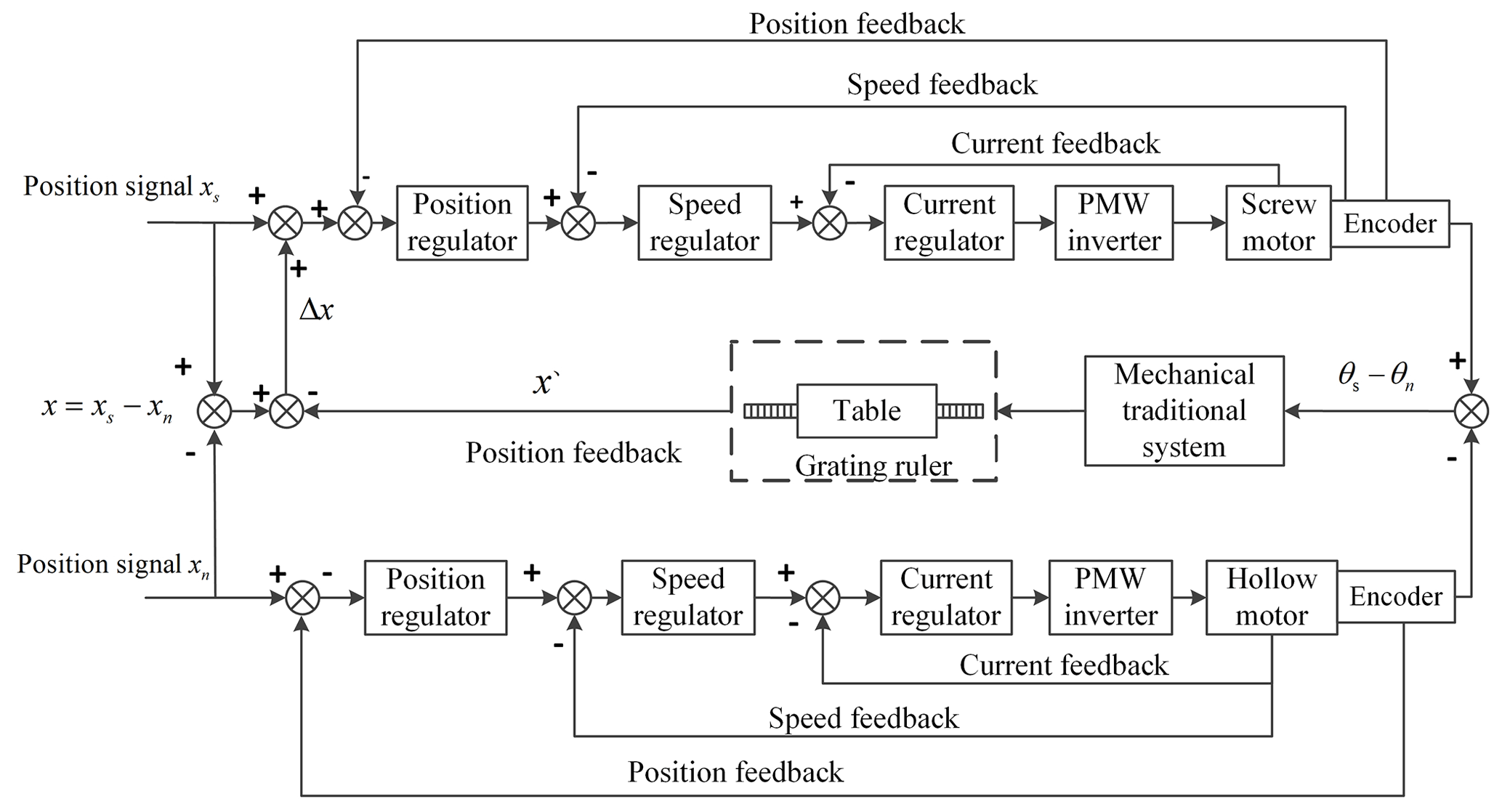
2.1 The DDFS control strategy
The control strategy of the DDFS is shown in Fig. 2, in which xs, xn and x′ represent the ideal position signal of the screw motor, the ideal position signal of the nut motor and the position measured by grating ruler of the table. To avoid the low-speed crawling area of a single motor, higher speeds for the screw and the hollow motors are given in the DDFS. When the differential table displacement is required, the differential position signal is generated by the ball screw pair to drive the table motion. The table position is compared with xt after the position feedback through the grating ruler, and the error is fed back to the screw motor controller, so the screw motor is adjusted to form a closed-loop control. When the CDFS is used in the DDFS, the table position signal is given to the screw motor, i.e., x=xs, and the hollow motor position xn=0. Again, the table position is compared with xs after the position feedback through the grating ruler, and the error is fed back to the screw motor control, so the screw motor is adjusted to form a closed-loop control.
3.1 Dynamic modeling of the CDFS
When the hollow servo motor does not rotate in the DDFS, the dynamic modeling of the CDFS can be illustrated in Fig. 3.
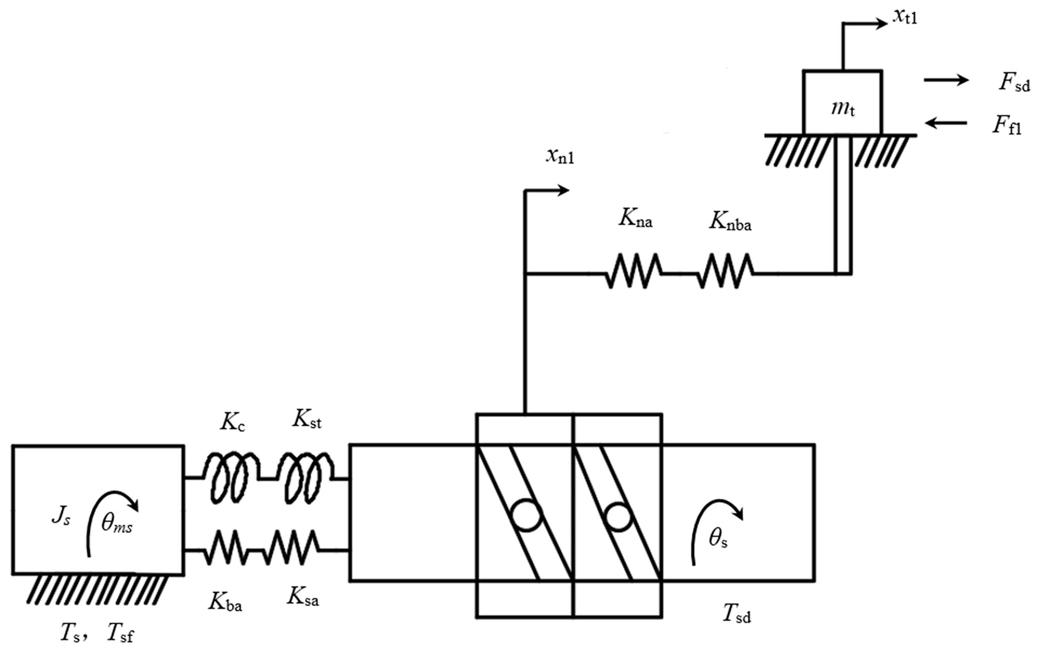
The equation of motion of the CDFS can be described in Eq. (1) (Yu et al., 2016).
where Ts is the electromagnetic torque of the screw motor. Tsf is the equivalent friction torque at the screw motor shaft, including the friction torque at the ball screw, the screw support bearing and the screw motor. Tsd is the output torque generated by the interaction between the screw shaft and nut. Js is the equivalent moment at the screw motor shaft, including the screw motor shaft, coupling and screw shaft. θms is the rotation angle of the screw motor. θs is the rotation angle of the screw shaft. Fsd is the driving force acting on the table. Ff1 is the friction force at the table. xn1 is the axial displacement of the nut. ph is the lead of the ball screw, η is the transmission efficiency of the feed system, H is the screw nut transmission ratio.
The equivalent torsional stiffness Kt1 of the drive system for the CDFS is shown in Eq. (2) (Wang et al., 2018).
where Kc is the torsional stiffness of the coupling, and Ksθ is the torsional stiffness of the screw shaft.
The equivalent axial stiffness Ka of the drive system for the CDFS is shown in Eq. (3) (Wang et al., 2018).
where Kba is the axial stiffness of the bearing, Ksa is the axial stiffness of the screw shaft, Kna is the axial stiffness of the nut and Knba is the axial stiffness of the nut bearing.
The axial rigidity of the screw is shown in Eq. (4) (Wang et al., 2018):
where E is the elastic modulus of the screw shaft, d is the diameter of the screw shaft, l is the span between the screw supports and a is the distance from the action point to the support.
The comprehensive equivalent stiffness of the DDFS is shown in Eq. (5) (Yu et al., 2016).
The axial displacement xt1 of the table can be expressed as shown in Eq. (6) (Wang et al., 2018).
3.2 Dynamic modeling of the DDFS
The dynamic modeling of the DDFS can be illustrated in Fig. 4.
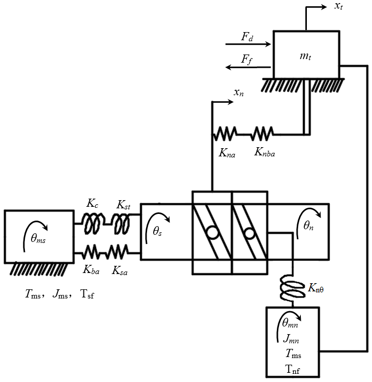
It is assumed that the rotation angle of the screw motor is larger than that of the hollow motor, and the torsional deformation between the screw motor and the screw shaft and between the hollow motor and the screw nut are ignored at the same time. The equation of motion of the DDFS can be described in Eq. (7) (Wang et al., 2019).
where Tn is the electromagnetic torque of the hollow motor. Tnf is the friction torque equivalent to the hollow motor shaft, including the friction torque at the ball screw, the nut support bearing and the hollow motor. Td is the output torque generated by the interaction between the screw shaft and nut. Jn is the moment of inertia equivalent to the hollow motor shaft, including the hollow motor shaft, screw nut and connecting flange. θn is the rotation angle of the screw nut.
Eq. (8) can be obtained by the motion analysis of the table (Wang et al., 2019).
In the DDFS, friction can be subdivided into the following three parts: friction torque equivalent to the screw motor shaft, including the friction torque at the screw motor bearing, the screw support bearing, and the ball screw; the friction torque equivalent to the hollow motor shaft, including the friction torque of the hollow motor bearing and the nut bearing; and the friction force at the table.
4.1 Friction modeling of the screw motor shaft
The friction modeling of the screw motor shaft is shown in Eq. (9) (Du et al., 2018).
where Tsf is the friction torque equivalent to the screw motor shaft, σ0s is the stiffness coefficient of the screw motor shaft, σ1s is the damping coefficient of the screw motor shaft, σ2s is the viscous friction coefficient of the screw motor shaft, Tnsr is the maximum static friction torque of the screw motor shaft, Tscr is the Coulomb friction torque of the screw motor shaft and θsr is the Stribeck velocity of the screw motor shaft.
4.2 Friction modeling of the hollow motor shaft
The friction modeling of the hollow motor shaft is shown in Eq. (10) (Du et al., 2018).
where Tnf is the friction torque equivalent to the hollow motor shaft, σ0n is the stiffness coefficient of the hollow motor shaft, σ1n is the damping coefficient of the hollow motor shaft, σ2n is the viscous friction coefficient of the hollow motor shaft, Tnsr is the maximum static friction torque of the hollow motor shaft, Tncr is the Coulomb friction torque of the hollow motor shaft and θnr is the Stribeck velocity of the of the hollow motor shaft.
4.3 Friction modeling of the linear guide
The friction modeling of the linear guide is shown in Eq. (11) (Du et al., 2018).
where Flf is the equivalent friction force at the linear guide, σ0l is the stiffness coefficient of the linear guide, σ1l is the damping coefficient of the linear guide, σ2l is the viscous friction coefficient of the linear guide, Fls is the maximum static friction force of the linear guide, Flc is the Coulomb friction force of the linear guide, and vsl is the Stribeck velocity of the linear guide.
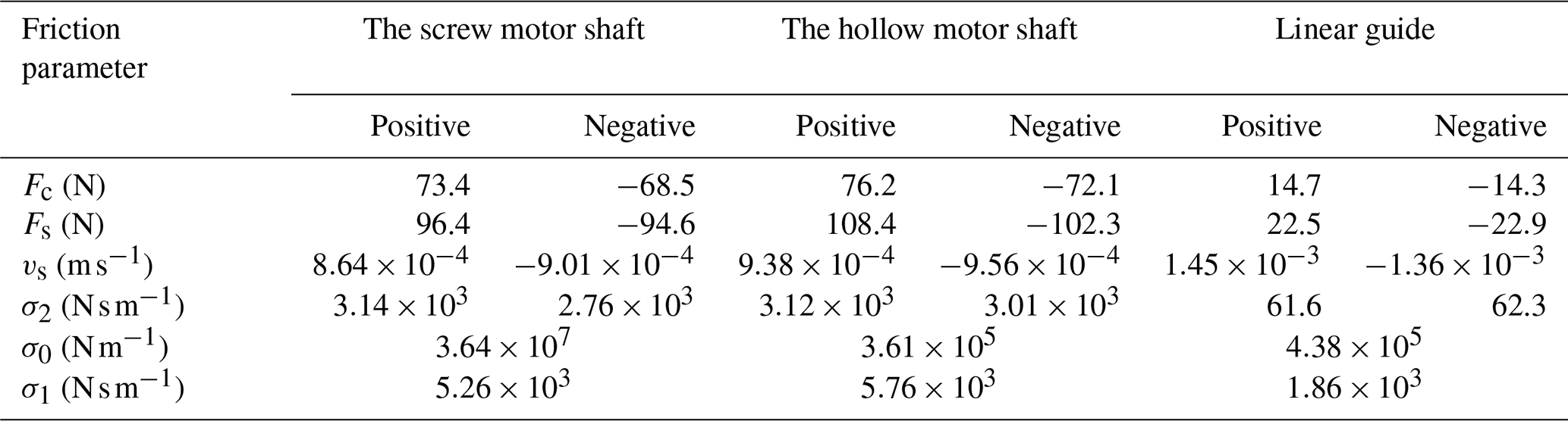
In order to compare the friction parameters between the screw drive shaft, the nut drive shaft and the linear guide, we divided the torque defined in Eqs. (9) and (10) of friction parameter values by the coefficient to convert into force. The identification results of the friction parameters are shown in Table 1 according to the following references: Liu et al. (2015) and Du et al. (2018). The direction away from the screw motor is positive, and the direction close to the screw motor is negative in Table 1.
5.1 The simulation platform of the DDFS
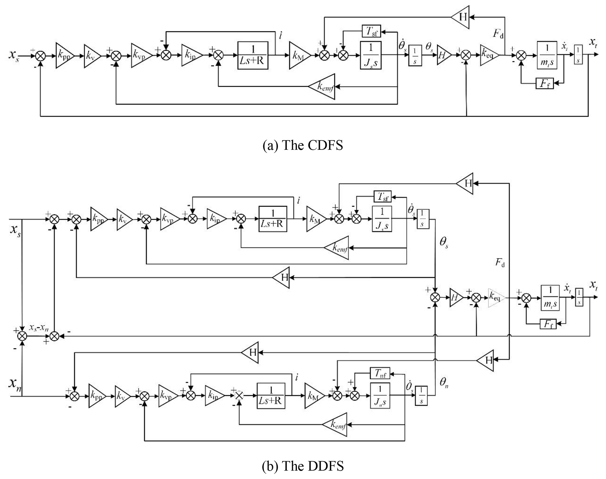
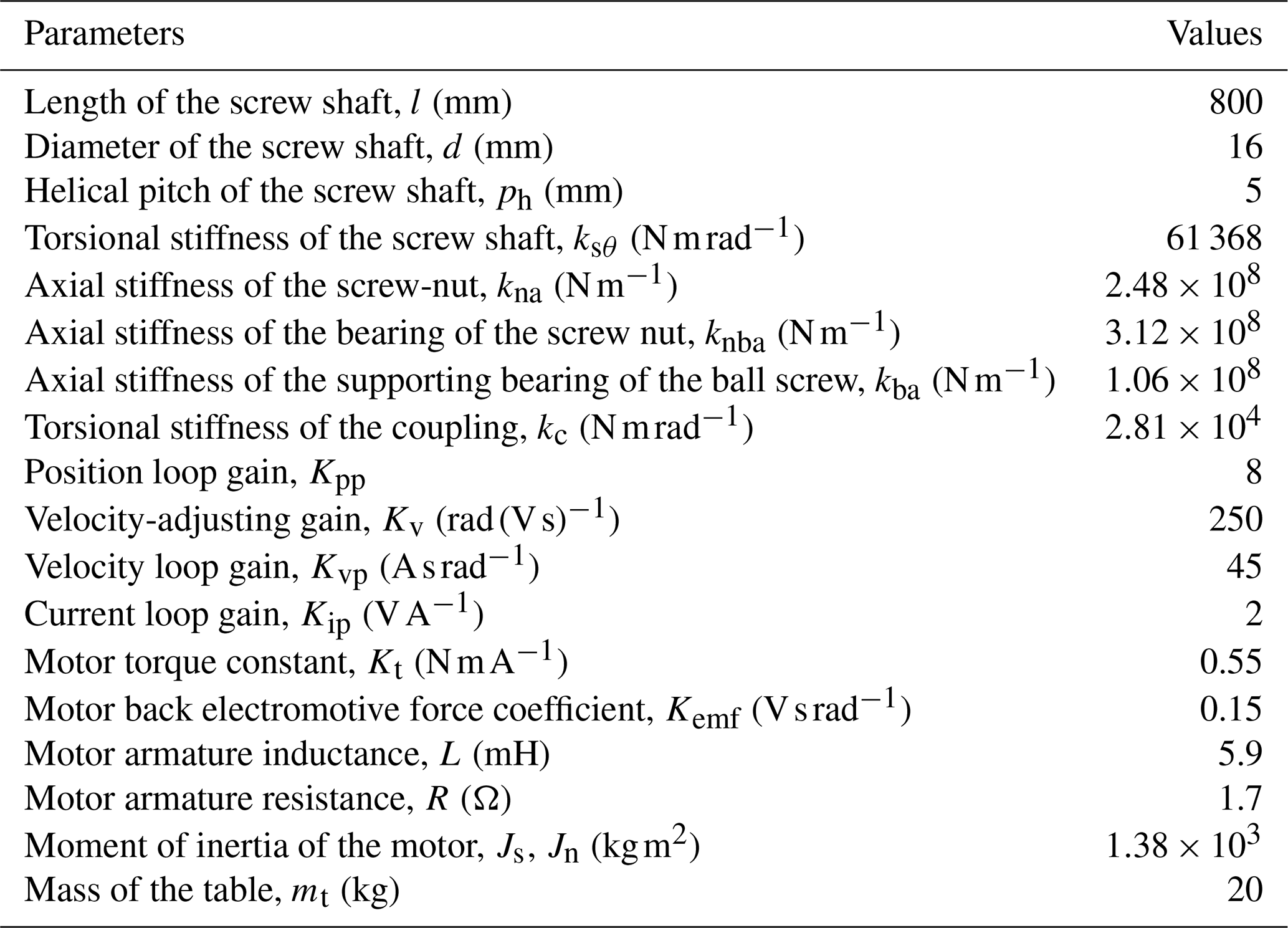
The simulation models of the CDFS and the DDFS are established in MATLAB according to the established dynamic and friction models. To compare and study the critical creeping speed of the table by using different driving methods, we set the same control parameters for the two motors. Figure 5a and b are the CDFS and DDFS control block diagrams established in MATLAB/Simulink. The parameters of the DDFS are shown in Table 2.
5.2 Constant speed analysis of the table in the middle of the screw shaft
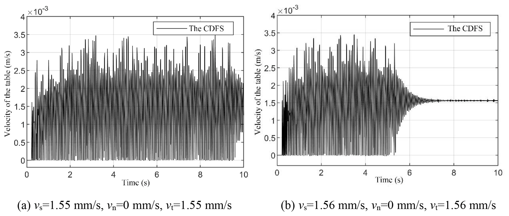
Keq is 2.16×10⁷ N m−1, when the table is in the middle of the screw shaft. Figure 6 shows the velocity of the table at different velocities for the CDFS. Figure 6a shows that the table crawls at 1.55 mm s−1 for the CDFS. This is because the command velocity of the table is lower than the Stribeck velocity of the table. Figure 6b shows that the velocity of the table has stabilized at 1.56 mm s−1 after 7 s of adjustment time for the CDFS. Therefore, the critical creeping velocity of the table is about 1.56 mm s−1 for the CDFS.
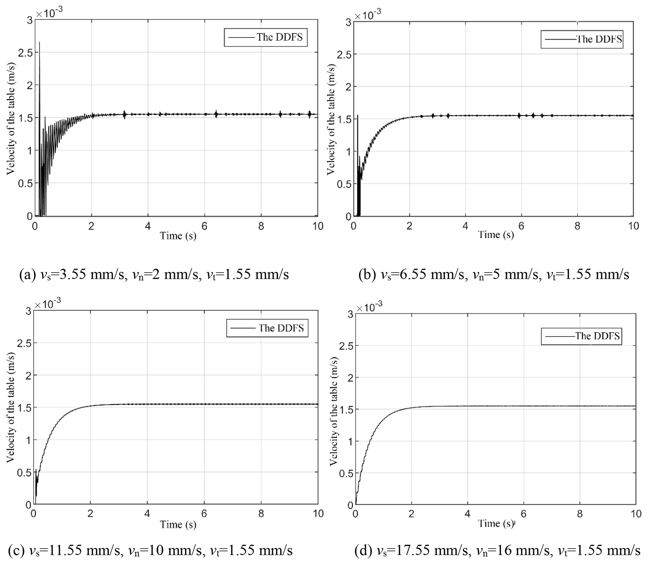
Figure 7 shows the speed of the table at 1.55 mm s−1, when the selected different speeds of the two motors are superimposed at the ball screw pair for the DDFS. The hollow motor keeps a constant speed vn all the time in Fig. 7. In order to avoid low-speed crawling of the CDFS, the speed of both motors in the DDFS is selected to be greater than the critical crawl speed of the CDFS (1.56 mm s−1).
Figure 7 shows that when the velocity of the table is 1.55 mm s−1, the velocity overshoot and adjustment time of the table during the acceleration stage gradually decrease as the speed of the hollow motor increases. Figure 7 shows that when the speed of the hollow motor is greater than 10 times the critical creeping speed of the CDFS, there is almost no significant change in the acceleration stage velocity and adjustment time of the table for the DDFS. Therefore, the speed of the hollow motor should be 10 times greater than the critical creeping speed of the CDFS to obtain a stable table velocity in the DDFS.
The speed of the two motors in the DDFS is 10 times greater than the critical creeping speed of the screw servo motor of the CDFS. The obtained critical creeping speed of the table is 0.5 mm s−1 for the DDFS, as shown in Fig. 8.
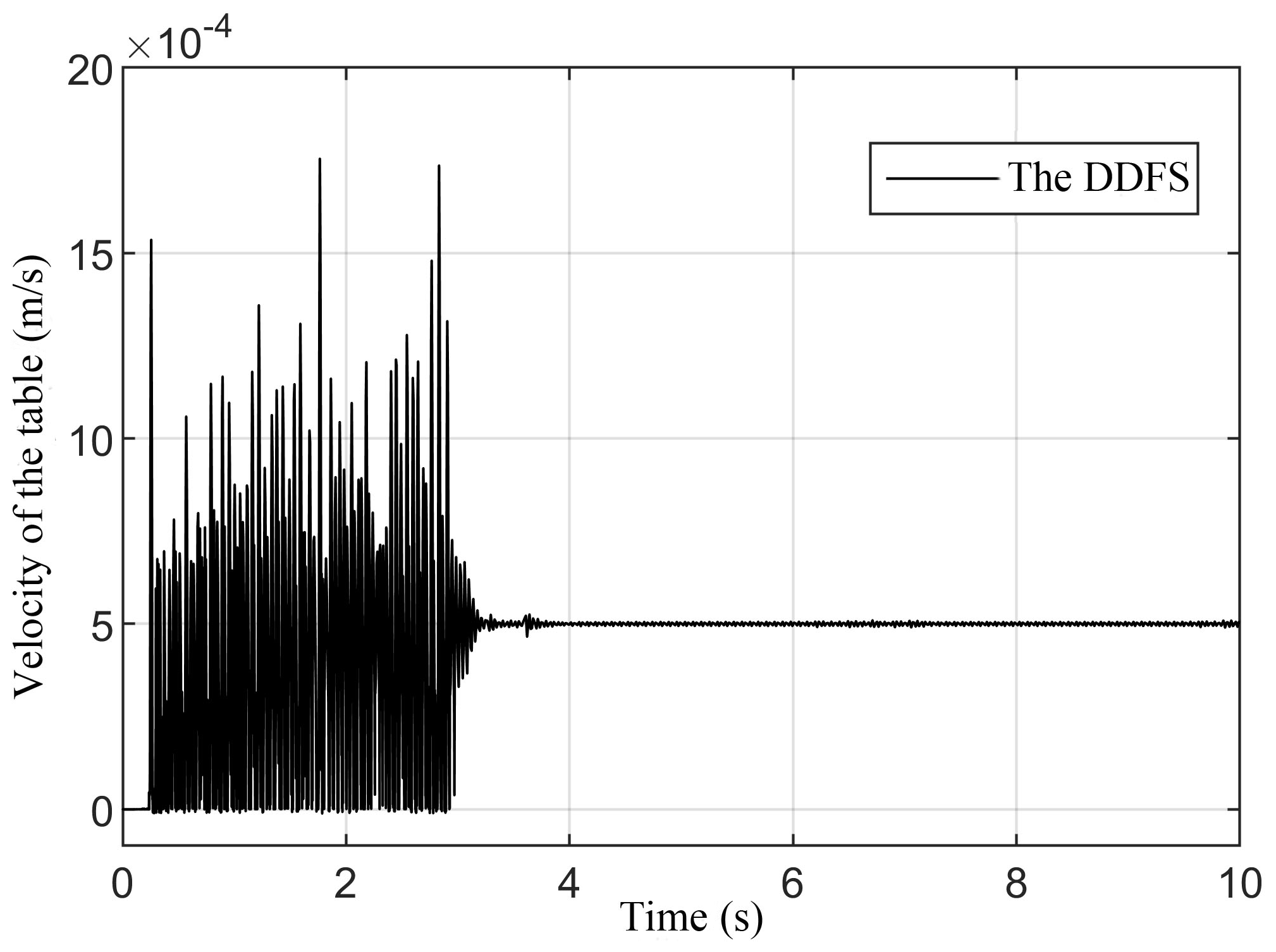

Figure 6 indicates that the velocity of the table at 1.55 mm s−1 has a serious creep phenomenon in the CDFS, because the friction of the ball screw pair at low speed is in the pre-sliding friction zone. Figures 7 to 8 indicate that a lower stable velocity of the table is achieved for the DDFS compared with the CDFS, because the speed of both motors in the DDFS is higher than the critical creeping velocity of the CDFS. The two motors work in a relatively higher speed in the DDFS, which overcomes the influence of the Stribeck effect at low speed and avoids the frictional nonlinearity at low speed compared with the CDFS.
5.3 Variable speed analysis of the table in the middle of the screw shaft
To research the speed overshoot of the table under the sinusoidal speed signal for the DDFS compared with the CDFS, the table speed is set to 1.56 and 2 mm s−1, respectively, which is greater than the critical creeping speed of the table (1.56 mm s−1) for the CDFS. Figures 9 and 10 show the speed of the table for the CDFS compared with the DDFS in which the selected different speed amplitudes of the two motors are superimposed at the ball screw pair for the DDFS. In Figs. 9 and 10, vsp, vnp and vtp represent the sine speed amplitudes of the screw motor, hollow motor and table, respectively.
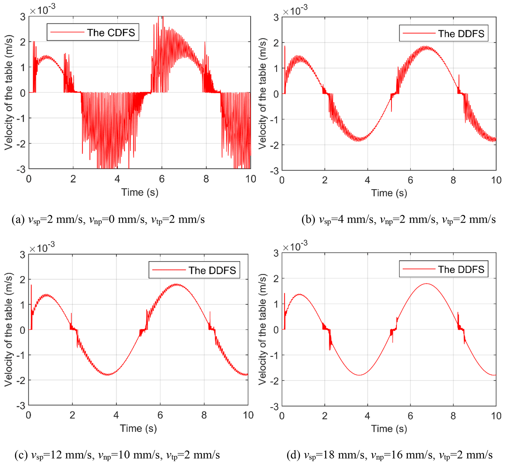
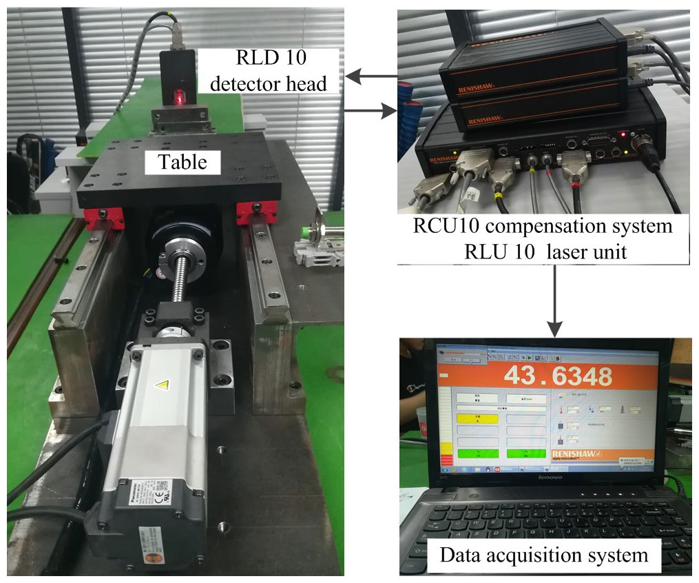
Figure 10b–d indicate that as the speed amplitude of the hollow motor increases, the overshoot of the table during speed reversal gradually decreases. Comparing with Fig. 10a, Fig. 10d indicates that the speed of the table only has a more obvious overshoot at the zero crossing for the DDFS when the amplitude speed of the hollow motor is 10 times greater than the critical creeping speed of the screw servo motor for the CDFS. Under the sinusoidal speed signal, the better speed tracking performance of the table is obtained for the DDFS compared with the CDFS.
To verify the accuracy of the modeling of the DDFS, the critical creeping speed of different driving modes was measured when the table was fed at a low speed. The critical creeping speed test of the DDFS is shown in Fig. 11.
The simulation in Sect. 5 indicates that the speed of the hollow motor should be 10 times greater than the critical creeping speed of the CDFS to obtain a stable table speed in the DDFS. Therefore, the speed of the hollow motor vn is set to 20 mm s−1 in the DDFS for the experimental tests. The measured direct-drive servo system travel is 400 mm. A total of five measurement points are taken in the test. The Renishaw XL laser interferometer is used to measure the critical creeping speed of the DDFS compared with the CDFS, as shown in Fig. 12.
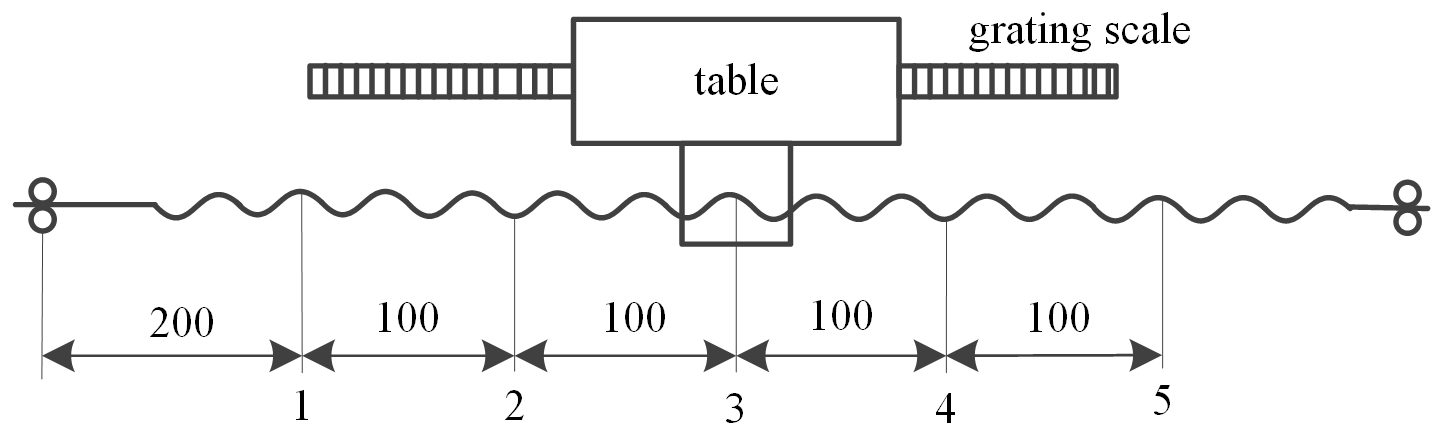
At each measurement point, a machine tool control program makes the table move uniformly along the axis. The table starts with a higher velocity, and we use a Renishaw XL laser interferometer to measure the dynamic response of the table. Then, we observe the table for crawling behavior. If no crawling occurs, we reset the velocity of the table and reduce the velocity in steps of 0.01 mm s−1 until it is found that the table is crawling. We record the position of the measurement point and the data of the critical creeping speed in turn. Since the relative displacement of the table is small, the measured critical crawling velocity can be regarded as the critical creeping velocity of the table at this measuring point.
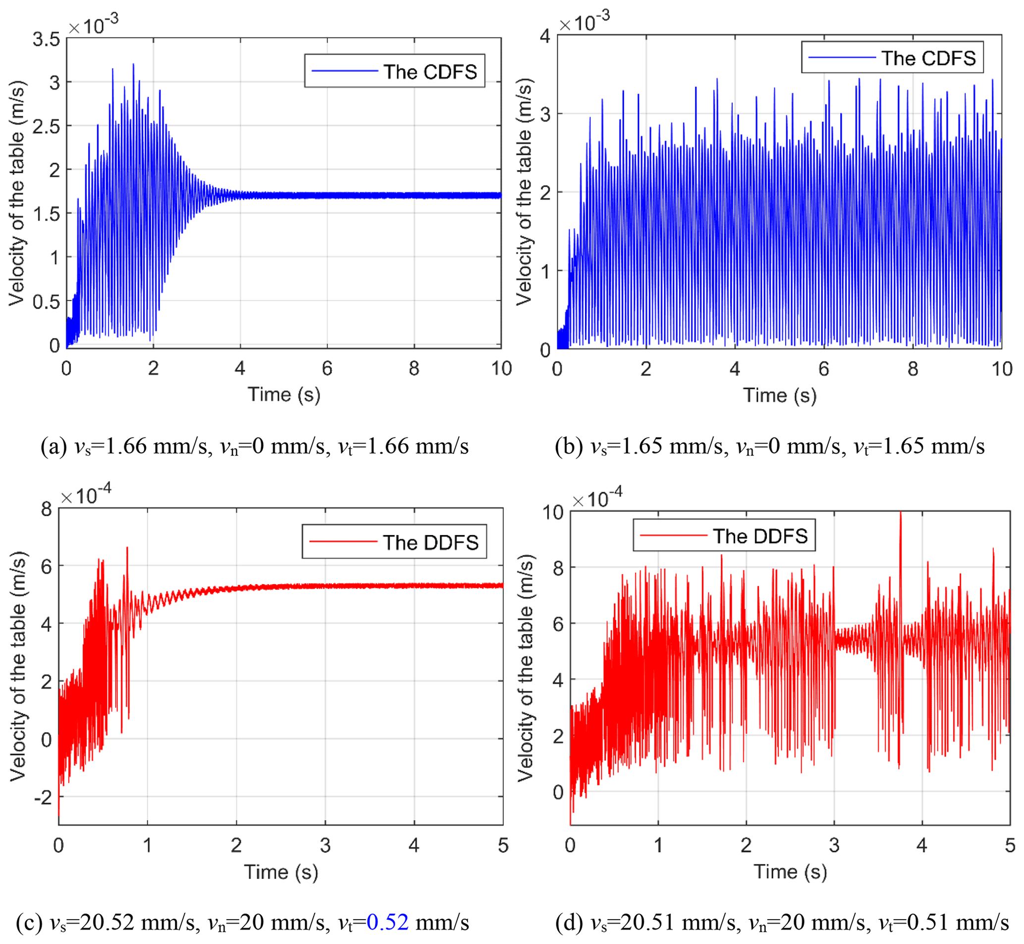
The critical creeping velocity of the table at measurement point 3 in the CDFS and the DDFS is shown in Fig. 13. Figure 13a and b show that the critical creeping speed of the table for the experiment is 1.66 mm s−1 in the CDFS. Figure 13c and d show that the critical creeping speed of the table for the experiment is 0.52 mm s−1 in the DDFS when the speed of the hollow motor vn is set to 20 mm s−1 in the DDFS.
After repeated measurements, the critical creeping velocity of the table at each measurement point in the DDFS and the CDFS is shown in Table 3. The relationship among the critical creeping velocity of the table, the axial stiffness of the ball screw, and the position of the table of the DDFS and the CDFS is shown in Fig. 14.
Table 3Critical creeping velocity of the table for the DDFS compared with the CDFS.

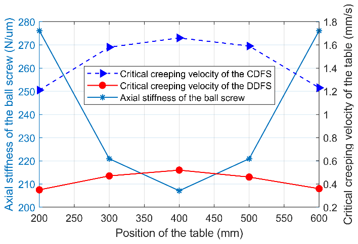
Figure 14Relationship between critical crawling velocity, axial stiffness of the ball screw and table position.
Figure 6 shows that the critical creeping speed of the table is about 1.56 mm s−1 for the CDFS in numerical simulations. Table 3 and Fig. 14 show that the critical creeping speed of the table for the experiment is 1.66 mm s−1 in the CDFS. The difference is caused by the manufacturing error of the ball screw pair, the error of the identified friction parameters and the error of the system stiffness value. Table 3 and Fig. 14 show that the critical creep velocity for the table decreased from 1.66 mm s−1 with the CDFS to 0.52 mm s−1 with the DDFS, when the table is in the middle position of the screw shaft. At the same measurement point, a lower critical creep velocity of the table is achieved for the DDFS compared with the CDFS. At the same time, it can be found that the critical creep velocity of the table at the five measuring points is different, and the critical creep velocity is greater as it approaches the middle position of the screw shaft. The friction conditions and control parameters at the five measuring points are consistent. Therefore, the critical creeping speed of the table is related to the axial rigidity of the ball screw shaft. The greater the axial rigidity of the ball screw, the lower the critical crawl speed of the table.
In this paper, the DDFS is developed to reduce the influence of the nonlinear friction at the ball screw pair of a linear feed system operating at low speeds, and some conclusions are drawn as follows.
-
The dynamic models of the CDFS and the DDFS are established. In the DDFS, friction can be subdivided into the following three parts: friction torque equivalent to the screw motor shaft, the friction torque equivalent to the hollow motor shaft and the friction force of the linear guides. The LuGre friction model is adopted as the friction model.
-
Compared with the CDFS, a lower stable speed of the table is achieved in the DDFS, because the speed of both motors in the DDFS is higher than the critical creeping speed of the CDFS. The two motors work at a relatively higher speed in the DDFS, which overcomes the influence of the Stribeck effect at low speed and avoids the frictional nonlinearity at low speed. The speed of the hollow motor should be 10 times greater than the critical creeping speed of the CDFS to obtain a stable table speed in the DDFS.
-
The critical creeping speed of the table is related to the axial rigidity of the ball screw shaft. And the greater the axial rigidity of the ball screw, the lower the critical creeping velocity of the table.
All data included in this study are available upon request by contacting the corresponding author.
ZW made substantial contributions to the conception and design, the acquisition, the analysis, and the interpretation of data for the work. He also drafted the work and revised it critically for important intellectual content. ZW made a contribution to the acquisition of simulation experimental data and data collation. XF supervised and structured the process of the paper. HY helped with making figures. HJ helped with the writing and language.
The authors declare that they have no conflict of interest.
Publisher's note: Copernicus Publications remains neutral with regard to jurisdictional claims in published maps and institutional affiliations.
The authors wish to thank the university-level key projects of Anhui University of Science and Technology (grant no. xjzd2020-10) for the support.
This research has been supported by the Science and Technology Development Plan of Shandong Province (grant no. 2015GGX103036) and the Innovative Research Group Project of the National Natural Science Foundation of China (grant no. 51375266).
This paper was edited by Dario Richiedei and reviewed by three anonymous referees.
Armstrong-Helouvry, B., Dupont, P., and Canudas de Wit, C.: A survey of models, analysis tools and compensation methods for the control of machines with friction, Automatica, 30, 1083–1138, https://doi.org/10.1016/0005-1098(94)90209-7, 1994.
Canudas de Wit, C., Olsson, H., Astrom, K. J., and Lischinsky, P.: A new model for control of systems with friction, IEEE T. Automat. Contr., 40, 419–425, https://doi.org/10.1109/9.376053, 1995.
Chen, J. S., Huang, Y. K., and Cheng, C. C.: Mechanical model and contouring analysis of high-speed ball-screw drive systems with compliance effect, Int. J. Adv. Manuf. Tech., 24, 241–250, https://doi.org/10.1007/s00170-003-1777-9, 2004.
Du, F., Zhang, M., Wang, Z., Yu, C., Feng, X., and Li, P.: Identification and compensation of friction for a novel two-axis differential micro-feed system, Mech. Syst. Signal Pr., 106, 453–465, https://doi.org/10.1016/j.ymssp.2018.01.004, 2018.
Han, S. I. and Lee, J. M.: Adaptive dynamic surface control with sliding mode control and RWNN for robust positioning of a linear motion stage, Mechatronics, 22, 222–238, https://doi.org/10.1016/j.mechatronics.2012.01.007, 2012.
Guo, K., Pan, Y. P., and Yu, H. Y.: Composite Learning Robot Control with Friction Compensation: A Neural Network-Based Approach, IEEE T. Ind. Electron., 66, 7841–7851, https://doi.org/10.1109/TIE.2018.2886763, 2018.
Jiang, N. J., Xu, J., and Zhang, S.: Distributed Adaptive Synchronization Control with Friction Compensation of Networked Lagrange Systems, Int. J. Control Autom., 16, 1038–1048, https://doi.org/10.1007/s12555-017-0429-z, 2018.
Kong, X. D., Yu, B., Quan, L. X., Ba, K. X., and Wu, L. J.: Nonlinear mathematical modeling and sensitivity analysis of hydraulic drive unit, Chin. J. Mech. Eng., 5, 999–1011, https://doi.org/10.3901/cjme.2015.0626.083, 2015.
Kumar, N. S., Shetty, A., Shetty, A., Ananth, K., and Shetty, H.: Effect of spindle speed and feed rate on surface roughness of Carbon Steels in CNC turning, Procedia Engineer., 38, 691–697, https://doi.org/10.1016/j.proeng.2012.06.087, 2012.
Lee, D. H. and Ahn, J. W.: Dual Speed Control Scheme of Servo Drive System for a Nonlinear Friction Compensation, IEEE T. Power Electr., 23, 959–965, https://doi.org/10.1109/TPEL.2007.915046, 2008.
Lee, W., Lee, C.-Y., Jeong, Y. H., and Min, B.-K.: Distributed Component Friction Model for Precision Control of a Feed Drive System, IEEE-ASME T. Mech., 20, 1966–1974, https://doi.org/10.1109/TMECH.2014.2365958, 2015.
Liu, L. and Wu, Z.: Comprehensive parameter identification of feed servo systems with friction based on responses of the worktable, Mech. Syst. Signal Pr., 64, 257–265, https://doi.org/10.1016/j.ymssp.2015.04.012, 2015.
Liu, Y. T., Higuchi, T., and Fung, R. F.: A novel precision positioning table utilizing impact force of spring-mounted piezoelectric actuator – part I: experimental design and results, Precis. Eng., 27, 14–21, https://doi.org/10.1016/S0141-6359(02)00180-0, 2003.
Lopes, R. A. M., Carrara, V., and Kuga, H. K.: Stepwise modeling with friction/inertia effects separation and velocity control with dynamic compensation of a reaction wheel, Comput. Appl. Math., 38, 1–11, https://doi.org/10.1007/s40314-019-0784-x, 2019.
Shi, X. and Polycarpou, A. A.: A Dynamic Friction Model for Unlubricated Rough Planar Surfaces, J. Tribol., 125, 788–796, https://doi.org/10.1115/1.1573229, 2003.
Urbakh, M., Klafter, J., Gourdon, D., and Israelachvili, J.: The nonlinear nature of friction, Nature, 430, 525–528, https://doi.org/10.1038/nature02750, 2004.
Wang, Z., Feng, X., Li, P., and Du, F.: Dynamic modeling and analysis of the nut-direct drive system, Adv. Mech. Eng., 10, 1–11, https://doi.org/10.1177/1687814018810656, 2018.
Wang, Z., Feng, X., Du, F., Li, H., and Su, Z.: A novel method for smooth low-speed operation of linear feed systems, Precis. Eng., 60, 215–221, https://doi.org/10.1016/j.precisioneng.2019.08.009, 2019.
Xiang, H. B., Qiu, Z. R., and Li, X. F.: Simulation and Experimental Research of Non-linear Friction Compensation for High-Precision Ball Screw Drive System, the 9th International Conference on Electronic Measurement & Instruments, Beijing, China, 16-19 August 2009, 607–609, https://doi.org/10.1109/ICEMI.2009.5274257, 2009.
Yu, H. and Feng, X.: Dynamic Modeling and Spectrum Analysis of Macro-Macro Dual Driven System, J. Comput. Nonlin. Dyn., 11, 208–212, https://doi.org/10.1115/1.4032245, 2016.
- Abstract
- Introduction
- The DDFS description
- Dynamic modeling of the CDFS and the DDFS
- Friction modeling of the DDFS
- Simulation and analysis of critical creeping speed of the DDFS
- Experiment of the critical creep velocity of the table in the CDFS and in the DDFS
- Conclusions
- Data availability
- Author contributions
- Competing interests
- Disclaimer
- Acknowledgements
- Financial support
- Review statement
- References