the Creative Commons Attribution 4.0 License.
the Creative Commons Attribution 4.0 License.
 | 08 Jul 2021
Semi-numerical analysis of a two-stage series composite planetary transmission considering incremental harmonic balance and multi-scale perturbation methods
Siyuan An
Yongmei Wang
Jiafu Ruan
Baixue Fu
This study conducts an analytical investigation of the dynamic response characteristics of a two-stage series composite system (TsSCS) with a planetary transmission consisting of dual-power branches. An improved incremental harmonic balance (IHB) method, which solves the closed solution of incremental parameters passing through the singularity point of the analytical path, based on the arc length extension technique, is proposed. The results are compared with those of the numerical integration method to verify the feasibility and effectiveness of the improved method. Following that, the multi-scale perturbation (MsP) method is applied to the TsSCS proposed in this subject to analyze the parameter excitation and gap nonlinear equations and then to obtain the analytical frequency response functions including the fundamental, subharmonic, and superharmonic resonance responses. The frequency response equations of the primary resonance, subharmonic resonance, and superharmonic resonance are solved to generate the frequency response characteristic curves of the planetary gear system (PGS) in this method. A comparison between the results obtained by the MsP method and the numerical integration method proves that the former is ideal and credible in most regions. Considering the parameters of TsSCS excitation frequency and damping, the nonlinear response characteristics of steady-state motion are mutually converted. The effects of the time-varying parameters and the nonlinear deenthing caused by the gear teeth clearance on the amplitude–frequency characteristics of TsSCS components are studied in this special topic.
- Article
(4481 KB) - Full-text XML
- BibTeX
- EndNote


Planetary gear systems (PGSs) are widely used in various fields such as ships, aviation, automobiles, machinery, and metallurgy based on their unique advantages. However, their vibration and noise have always been hot topics in academia and the focus of discussion in the engineering community. Especially in conventional power underwater devices, the PGS noise has exceeded 100 dB. Planetary gears are the most critical underwater components of ships that transfer real-time power and time-varying motion. Owing to its compact transmission structure, strong anti-scuffing bearing performance, and high transmission precision, the planetary gear transmission is widely used in various mechanical systems. The application of the PGS in the underwater military industry has created an urgent demand for lightweight and reliable structures (Inalpolat and Kahraman, 2009). Planetary gears have various dynamic response properties due to their complex inherent characteristics (Feng and Zuo, 2012). The dynamic behavior analysis of the alternating meshing process is a popular area of study in the design and applications of various planetary gear mechanisms and their transmission systems (Hotait and Kahraman, 2013; He et al., 2017; Pan et al., 2018). Many researchers have been working on new simulation analysis methods to gain an in-depth understanding of the dynamic meshing transients of planetary gears (Chen et al., 2019; Suslin and Pilla, 2017; Morgado et al., 2008). Numerous studies have been performed on the dynamic behavior analysis method, which plays an important role in determining the performance of planetary gears. In addition, the machinery industry is paying more attention to the dynamic characteristics of planetary gear drives and the resulting vibrations and noise (Hu et al., 2017; Weis et al., 2017; Lin and Zhang, 2018).
A two-stage series composite system (TsSCS), consisting of a PGS with dual-power branches, is a complex and flexible mechanical system that comprises several parts (Zhou et al., 2020). A TsSCS is generally divided into two parts: the transmission system (gear train, transmission shaft, and bearing) and the structural system (gearbox, dual-branch composite planetary gearbox, dynamometer, and bracket) (Sánchez et al., 2017). The increasing number of studies on the vibrations and noise produced by underwater devices, particularly on controlling the noise produced by the power rear transmission system of underwater devices, must account for the TsSCS and its meshing process, in addition to the real-time dynamic meshing force acting on the system.
Few theoretical studies consider the TsSCS with a planetary transmission consisting of dual-power branches as a subject (Liang et al., 2018). It is important to possess some professional design knowledge while studying the unique kinematics and geometric characteristics of a TsSCS consisting of a planetary transmission with dual-power branches (Ege et al., 2018). The TsSCS, with a dual-power branch planetary transmission, is preferred to the horizontal shaft gear deceleration system, especially in applications requiring high linear speed power density designs and kinematic flexibility to optimize different speed ratios (Marchetti et al., 2020; Garambois et al., 2019; Acri et al., 2019). It has been demonstrated that reducing the spoke thickness to increase gear flexibility also resolves several internal gear and planetary frame errors and operational errors, in addition to making the system lighter (Yang et al., 2021). Moreover, a flexible internal gear improves the load sharing between planets, which is an important feature if manufacturing- and assembly-related gear and carrier errors are inevitable. Thus, it is difficult to quantify the factors that influence the TsSCS with a dual-power branch planetary transmission under quasi-static conditions.
Modals are the inherent characteristics of gear transmission systems (Wu et al., 2019; Wang et al., 2018; Dai et al., 2021). A modal analysis is used to determine the vibration characteristics of the designed structure or its transmission components. The modal analysis is a part of the structural dynamics analysis and is also the starting point for the subsequent transient dynamics, harmonic response, and spectrum analyses (Kosała, 2019). Each mode has a corresponding natural frequency, damping ratio, and mode shape (Rosa et al., 2020). A modal analysis is a modern technique that is used to study the dynamic characteristics of a transmission system structure, including modal analysis of linear vibration theory and experimental modal analysis (Bi et al., 2017). An experimental modal analysis can only be carried out after the components of the structure have been processed and assembled. However, it has a longer test cycle and is more expensive. In addition, it is easily affected by the quality of the processing and assembly steps. Thus, it is difficult to use these results in the design analysis stage (Arasan et al., 2021). As a result, the experimental analysis is used to verify the results of the analysis of the theoretical model and modify it accordingly. Various modal parameters, such as the modal frequency, shape, quality, stiffness, and damping, affect the dynamic load design (Rosa et al., 2020).
Since most of the internal, planetary, and sun gears are excluded from these models, it is not possible to study the effect of the internal gear thickness on the performance of the TsSCS and its effect on the stress acting on the planetary and sun gears and the load sharing between the planets. Similarly, it is not possible to accurately predict the shape and deflection of the gears. Although the abovementioned studies indicate that the adverse effects of the gear and planet carrier manufacturing errors can be minimized by improving the planetary load-sharing characteristics under quasi-static conditions, these modifications lead to increased gear contact stress. These static analyses alone cannot predict the actual design of the system because the increasing flexibility of the TsSCS causes its performance to change only under dynamic conditions. This might also lead to a rise in the stress acting on the gear. The current study, thus, studies the inherent characteristics of the TsSCS, constructs its dynamic model, and synthetically analyzes its inherent and dynamic response characteristics.
On such research topics, scholars have begun to carry out theoretical research on the dynamic characteristics of PGSs, including many aspects of the dynamic characteristics of PGSs, such as free vibration, dynamic response, load sharing, vibration control, and dynamic stability, but detailed study of dynamic characteristics of the TsSCS with a planetary transmission consisting of dual-power branches of underwater devices has not yet been reported.
As mentioned above, the overall structure of the subject of research has been revealed. In Sect. 2, the mathematical model of the semi-numerical analysis is presented. In Sect. 3, the simulation application (analysis and application of improved methods and simulation application of multi-scale perturbation analysis method) of the analysis method has been discussed in detail. In Sect. 4, the validation based on frequency response characteristic analysis has been highlighted.
The first step of the dynamic calculation is to determine the natural frequency and mode shape of the structure while ignoring its damping. These results reflect the basic dynamic characteristics of the structure and its response trend under dynamic loads. The double-branch composite transmission system test bench is considered to be a single elastic body. As shown in Fig. 2, a transmission diagram of the double-wide helical planetary composite system, with a two-level power branch, for high speed and heavy duty applications, has been proposed. The differential equation of motion describing the overall vibration of the test bench is given as
where , , and ut refer to the acceleration, velocity, and displacement vectors of the nodes in the vibration system, respectively. M, C, and K represent the mass, damping, and stiffness matrices of the vibration system, respectively. Qt represents the external force vector received by node. Only the inherent characteristics of the vibration system are modeled and solved in the modal analysis. The model does not contain external force terms and neglects the damping terms that are assumed to have an insignificant impact on the system. The differential equation of motion for an undamped free vibration system is given as
The resonance solution form of the equation is given as (Sakaridis et al., 2019)
where u is the displacement vector, and ϕ is the characteristic vector of the amplitude of the displacement vector u. ωn is the natural angular frequency.
The resonance form of the equation is a key to the numerical solution. It is derived under the assumption that all degrees of freedom of the vibrating structure move in a synchronous manner. During this process, the basic shape of the structure does not change; only the amplitude varies. According to the dimensionless differential equation of the planetary gear of the planetary gear train, its matrix form can be rewritten as
It is noteworthy that the stiffness matrix K is no longer symmetric due to the transient nature of the phase angle of the planetary gears.
2.1 Incremental harmonic balance and arc length extension method
The harmonic balance method uses a description function to approximate the nonlinearity caused by the gap and is widely used in PGSs (Acri et al., 2019). The excitation and response parameters are assumed to be harmonic functions and are substituted in the nonlinear equation. The approximate expressions of the response and phase parameters can thus be obtained using the condition of equal power coefficients. Since this method is not limited by the degree of nonlinearity, all the frequency response values can be obtained. However, owing to the limitations of the assumed excitation and response form, the accuracy of this method is not satisfactory, particularly if the first harmonic is considered. It results in the artificial loss of the superharmonic, subharmonic, or chaotic responses. Lau and Cheung proposed the incremental harmonic balance (IHB) method in 1981 to improve the accuracy of the existing harmonic balance method. A Taylor series expansion was performed on the nonlinear differential equations while ignoring the higher-order derivatives to obtain the differential equations in an incremental form. The Fourier series and the Galerkin method were then used to obtain nonlinear algebraic equations. The entire process is divided into an incremental component (Newton–Raphson method) and a harmonic balance component (Galerkin method). This method has the advantage of free control algorithm convergence accuracy, among many others, and is thus an effective method for solving complex nonlinear problems (Daneshjou et al., 2017). Rohan and Lukeš (2019) used the incremental harmonic balance method for a two-stage star gear train with multiple degrees of freedom; however, it is only used the response as an incremental parameter. If a singular point is encountered along the path of the solution branch, the quasi-arc length parameter is introduced. The original variables and parameters are assumed to be functions of the arc length. This condition is added to the original equation to smoothly track the path through the singular point (Guo et al., 2014). The harmonic balance method, based on the continuation of the arc-length, has been applied to the pure torsion model of a fixed shaft and a single-stage planetary transmission (Tomilina, 2015). The incremental harmonic balance method, based on the continuation of the arc length, is used to calculate the dynamic characteristic equation of the system used in this study. The two incremental parameters (response and fundamental frequency) are expressed in terms of the arc length to smoothly overcome the singular points along the path. The formula to calculate the steady-state response of a two-stage herringbone PGS is presented in this study. This method has not yet been applied to planetary gear transmission systems.
2.2 Incremental harmonic balance method
A new time variable τh=Ωτ is introduced in this method. The expression of y, initially written in terms of τ, is rewritten in terms of τh. As a result, Eq. (4) is written as
where M, C, and K are the mass matrix, damping matrix, and stiffness matrix of the TsSCS respectively. ωmi is the natural angular frequency. The incremental process is the first component of the IHB method. If yj0 and Ω0 are the solutions of Eq. (5), their neighboring points can be expressed as
where Δyi and ΔΩ are the incremental parameters.
By substituting Eq. (6) into Eq. (5) and omitting high-order small quantities, the incremental equation matrix can be obtained with Δyi and ΔΩ as the unknown quantities.
where R is the unbalanced force vector (also referred to as the residual correction term in some studies). If yj0 and Ω0 are exact solutions, then R=0.
The second component of the IHB method involves the harmonic balance process. The steady-state response of the system is described by a Fourier series. The response contains only odd harmonics and is given as follows.
The response of the system and its increment can be written in the following matrix form.
After substituting Eq. (11) into the incremental Eq. (7) and the unbalanced force Eq. (8), the Galerkin averaging process is applied to obtain the equations for the unknown quantities ΔA and ΔΩ.
where , , and .
2.3 Arc length extension method
The arc length parameter equation, corresponding to Eq. (5), can be expressed as
Assuming g(p)=pTp, and substituting the increments of A, Ω, and S in Eq. (13), the increment equation can be obtained, as shown below.
Figure 1 shows a part of the analytical balance path of the arc-length extension method. And Eq. (13) can be rewritten as
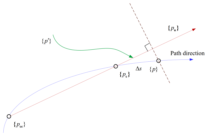
Figure 1Partial schematic diagram of the balance path based on the arc length extension method.
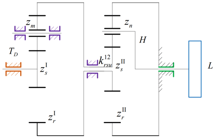
Figure 2Transmission diagram of a planetary composite system with a two-level power branch.
The initial values of the upper and lower points pu of the balance path are determined by the values of the previous two points, pc and Pcc.
The complete incremental equation can be obtained by combining Eqs. (12) and (14).
where Jp is the Jacobian matrix relative to {p}.
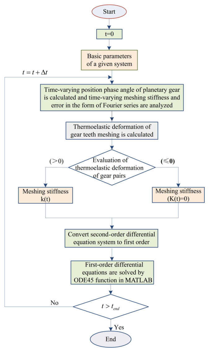
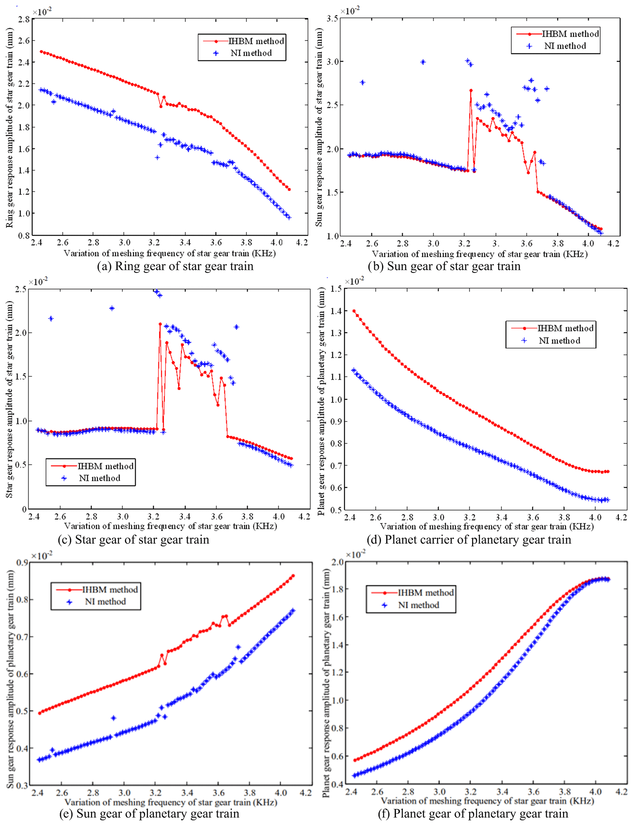
Figure 4Variation of the torsional response amplitude of each component of the PGS using the IHB method.
The above equation is expressed in an iterative form that can be easily calculated, as shown below.
Equation (18) represents the Newton–Raphson iterative equation that is obtained after introducing the arc length parameter. The arc length parameter is used to predict the value of the next solution from the current solution and is used as the initial value in the next iteration.
3.1 Analysis application of the improved method
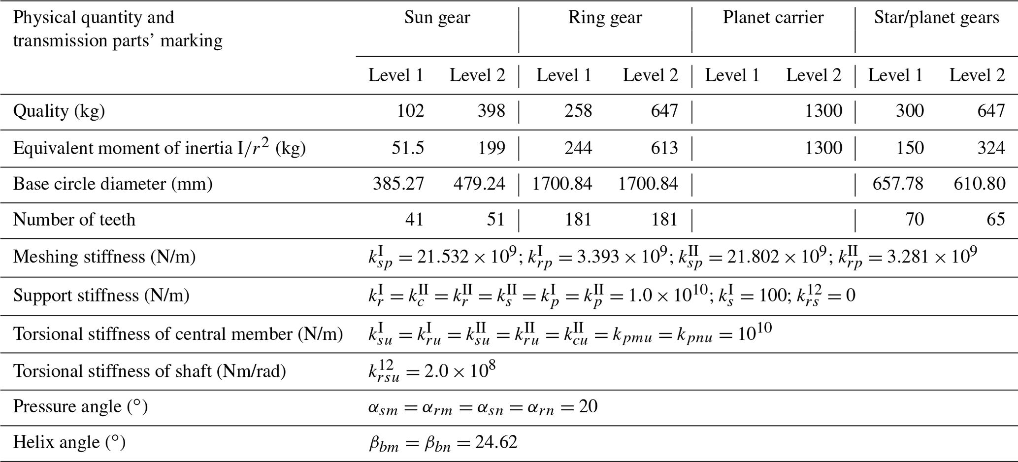
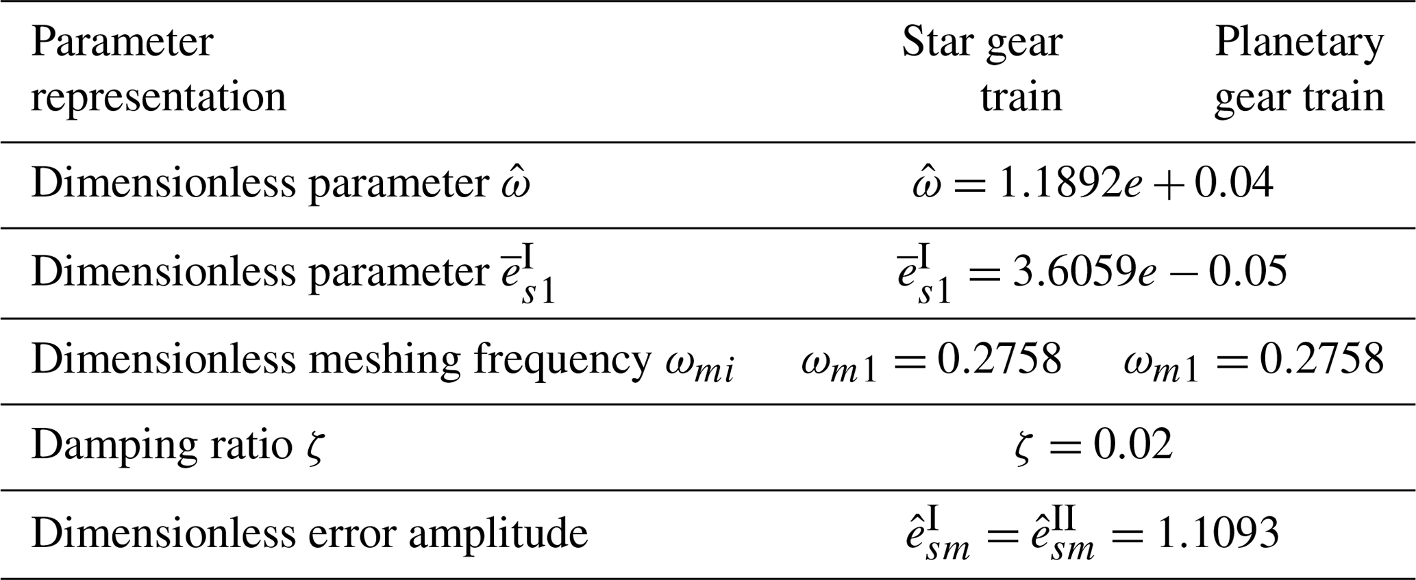
The transmission diagram of the double-wide helical planetary composite system, with a two-level power branch, for high speed and heavy duty applications, is shown in Fig. 2. The system is composed of a star gear train I (sun gear , planet gear zm, and ring gear ) that is connected to a planet gear train II (sun gear , planet gear zn, ring gear , and planet carrier H). The superscripts I and II correspond to the series of the component. The input power is transmitted to the load L by the sun gear . The input speed of the second-stage planetary gear train is reduced according to the deceleration of the first-stage planetary gear train, thereby increasing the stability and smoothness of the transmission. The system parameters are listed in Tables 1 and 2. The calculated nonlinear response characteristics of the system are shown in Figs. 3 to 5, which correspond to the time domain response history, phase diagram, and Poincaré mapping of the system, respectively. Owing to the space constraints in this paper, we have only mentioned the torsional response of the representative components. However, this does not imply that the translational response of the components can be neglected.
Since the number of unknowns exceeds the number of equations, the expected increment must be specified before performing the actual calculation. The increment specified in this article is equal to ΔΩ. Based on the structural flowchart of the improved incremental harmonic balance method depicted in Fig. 3 and the dimensionless parameters listed in Tables 1 and 2, the specific iterative process of the improved method is given as follows.
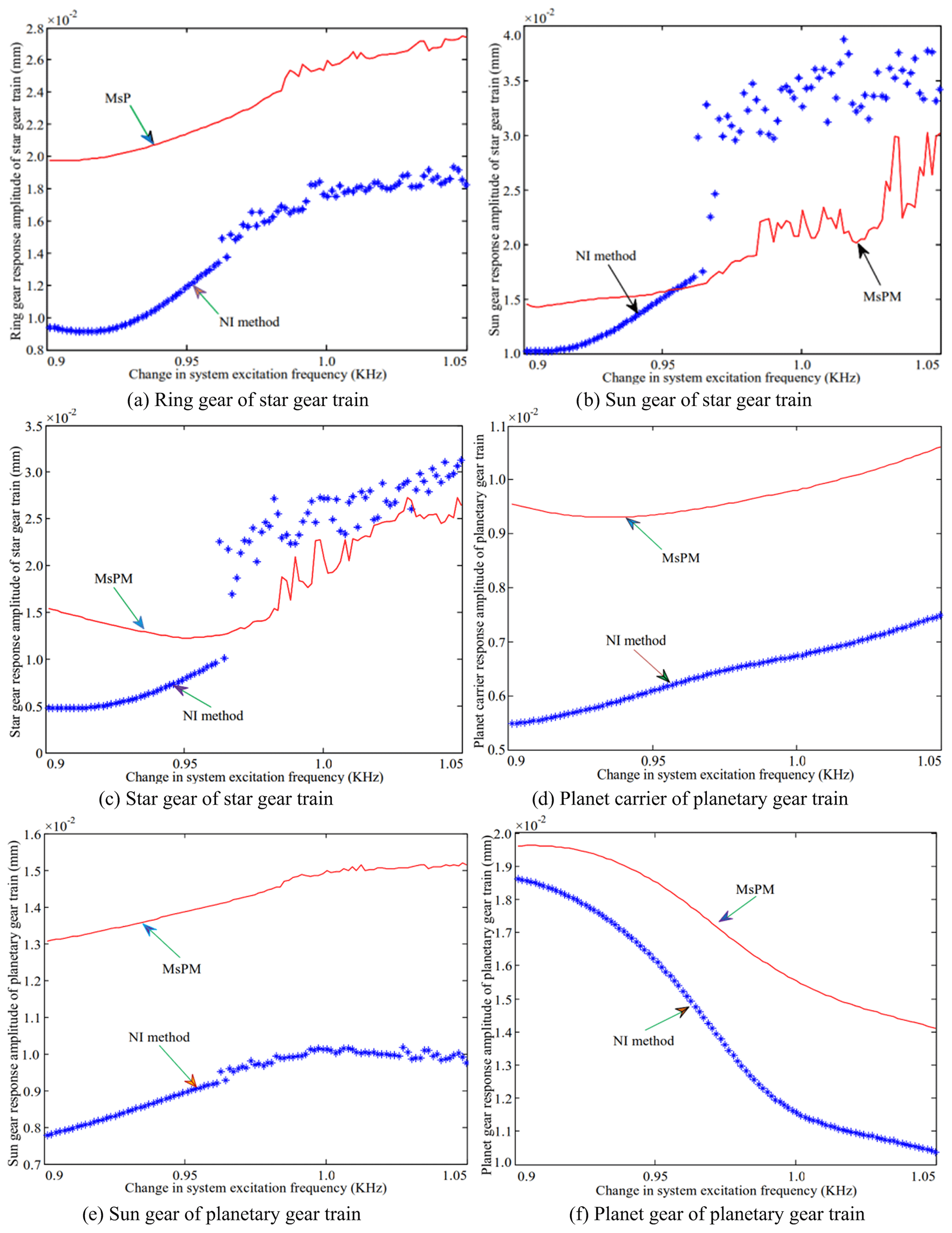
The amplitude–frequency characteristic curves of the system operating at the approximate working speed are shown in Fig. 4. The figure compares the results obtained by the incremental harmonic balance method and those obtained by the numerical integration (NI) method. The latter is based on the variable step size of the fourth and fifth steps, which is the Runge–Kutta method.
The meshing frequency lies in the range of 3.3–3.7 kHz, as shown in Fig. 4b and c. Amplitude jumps are observed in both the sun gear and star gear of the star gear system. The two methods are in this area. The amplitude values obtained from both the methods do not match as well in this region as they do in the others. In addition, the results of the numerical integration method indicate the presence of a resonance peak in other regions; however, the IHB method does not seem to indicate the presence of a resonance peak. This is because the number of harmonic response terms is insufficient.
The ring gear of the star gear system, shown in Fig. 4a, and the sun gear of the planetary gear system, shown in Fig. 4e, produce minimal amplitude resonance. The results obtained by the numerical method and IHB method follow a similar trend; however, a significant difference exists between the amplitude values. The variations in the amplitude of the planetary carrier, shown in Fig. 4d, and the planetary gears, shown in Fig. 4f, are relatively gentle. The curves obtained from the two methods gradually tend to become consistent with increasing mesh frequency, resulting in a significant amplitude variation of the planetary gears. This is consistent at a 4.0 kHz bit frequency. The above analysis demonstrates that the improved method is in agreement with the law of amplitude–frequency change for each part of the system, thereby illustrating the feasibility of this method.
3.2 Simulation application of the multi-scale perturbation analysis method
The incremental harmonic balance method, which is based on the arc-length continuation technique, is a semi-analytical and semi-numerical method. It is necessary to perform a purely analytical study of the dynamic characteristic equation of the system. Current studies adopt the multi-scale perturbation analysis method to obtain the analytical solutions of parametric excitation and gap nonlinear system equations (Li et al., 2019). The multi-scale perturbation (MsP) method can obtain the analytical frequency response functions of a system, including the fundamental, subharmonic, and superharmonic resonance responses (Tittus et al., 2020). Thus, this technique demonstrates the impact of important parameters on the response of the nonlinear dynamic characteristics, unlike conventional numerical methods.
The small parameter , is introduced in the first-order Fourier coefficient of the meshing stiffness of the sun gear and planetary gears in the planetary gear system.
refers to the average meshing stiffness and is written in its dimensionless form for each gear pair, as shown below.
where , ,
,
.
The time required for the contact gear pair to disengage is assumed to be negligible with respect to the response period, i.e., , where ξ is the disengagement time, and is the response period. The Fourier expansion of the non-meshed function of the contact gear pair is expressed in terms of the fundamental frequency Ω, as shown below.
The corresponding eigenvalue of Eq. (11) is expressed as
where K0 is the linear time-invariant average meshing stiffness matrix, and . Kd represents the change range matrix of the average meshing stiffness K0, with its mean value equal to zero. Kb is the support torsional stiffness matrix (including the support stiffness of the star and planet gears). Ke is the additional stiffness matrix generated due the transient phase angle of the planetary gear, , where , , and are the coefficient matrices related to , , and , respectively. The vibration mode is given by , and it satisfies the relation VTMV=I. The average stiffness matrix K is given below.
where , , , and are the coefficient matrices related to , , , and .
Substituting Eqs. (25)–(28) into Eq. (11), we obtain
where , , , .
The modal coordinate transformation y=Vz can be used to write the additional stiffness matrix coefficients in terms of the small parameters. The resulting modal coordinate form, obtained after the transformation of Eq. (31), is given as
where , , , , , , and , Epnqw, Esnqw, and Ernqw represent the elements in the qth row and ωth column of the matrices Epm, Esn, and Ern, respectively. Gsmqw, Grmqw, Gsnqw, and Grnqw represent the elements in the qth row and the ωth column of the matrices Gsm, Grm, Gsn, and Grm, respectively. The modal damping factor 2ζqcq has been introduced and rewritten in terms of the small parameter ε as ελq=2ζqcq. , where is the speed of the second stage planet carrier. The small parameter ε is related to the time change of the phase angle of the planet gear in the second stage. A multi-scale method is applied by introducing multi-scale variables such as τn=εnτ and . Based on the abovementioned variables, the perturbation equation with the first approximate solution is proposed, as shown below.
Table 1System parameters.
(1) The initial value y0 is fixed according to the excitation frequency Ω=Ω0. (2) The increment ΔA is obtained by substituting the value of the parameter ΔΩ in Eq. (18). Replace A with A+ΔA to obtain the updated values of the parameter Δy from Eq. (18). This is used to obtain Δy from Eq. (17). The modified solution y is then obtained from Eq. (12). The process is repeated until the value of the parameter A satisfies R=0. (3) A new increment is provided to Ω0 such that . The value of the parameter A that is obtained in (2) is set as the initial value. The harmonic balance process is repeated, and the value of the parameter A is updated until it meets the condition R=0. (4) The arc length parameter s is introduced to determine the initial value of the next point from the value of the parameters A and Ω obtained in (2) and (3). This is substituted as the initial value in Eq. (18), and the iteration step mentioned in (2) is repeated.

Equation (34) is the perturbation equation used to calculate the closed solution. The frequency response characteristics of the system under different excitations can be studied using this equation.
The amplitude–frequency characteristics of the system are obtained and studied after solving the frequency response equations under different resonance conditions according to the multi-scale perturbation analysis method. A natural frequency of 973.1 Hz is selected to study the frequency response characteristics of the system during resonance in the vibration mode of the planetary gear system. The amplitude–frequency characteristics of the system are analyzed and compared with the results obtained using the numerical integration method. The calculated amplitude–frequency characteristic curve is shown in Fig. 5. Figure 5a shows that the response amplitude of the ring gear of the star gear train calculated by the multi-scale method differs significantly from that of the numerical method. No amplitude jump was observed, as shown in Fig. 5b and c. The variation trends of the planetary carrier and gears of the planetary gear train, as shown in Fig. 5d and f, are identical. The trends followed by the variation of the responses in both methods are identical, as shown in Fig. 5e. The larger difference is also the magnitude of the amplitude. The difference between the values of the amplitude obtained through both methods is relatively large for the planet carrier and small for the planet gear.
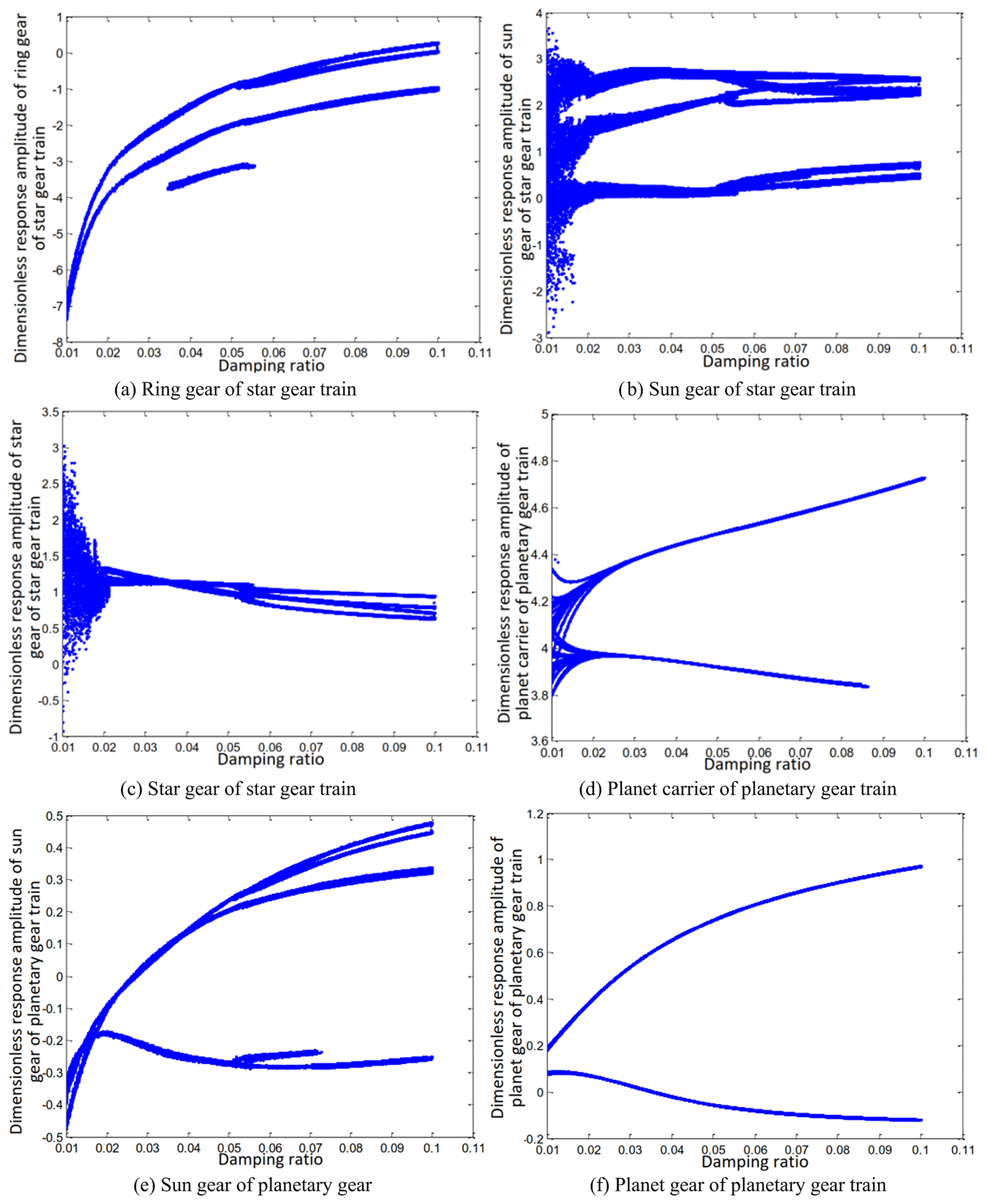
However, the variation of the sun gear in the middle planetary gear system is similar to that of the ring gear in the star gear system. The response amplitudes of the sun gear and the star gear in the star gear system are not consistent with those obtained from the numerical method. The variation trends obtained through both methods were also different. The impact of the variation of the damping ratio on the amplitude–frequency response characteristics, upon the introduction of the third harmonic error, is studied. It can be seen from Fig. 6 that the bifurcation characteristics of the system are complex, and the introduction of errors increases the influence of the damping ratio. The steady-state response of the ring and sun gears of the star gear train is either a non-harmonic periodic response or a simple harmonic periodic response, as shown in Fig. 6a and e. The gears of the planetary gear train always maintain a harmonic response without bifurcation, as shown in Fig. 6f. The steady-state response of the planetary carrier of the planetary gear train, as shown in Fig. 6d, is bifurcated from a single period to a double period when the damping ratio ζ is equal to 0.03. The steady-state response of the sun gear of the star gear system, as shown in Fig. 6b, directly branches from period doubling to a harmonic period response at ζ=0.035, and attains a chaotic state at ζ=0.023. The steady-state response of the star gear, as shown in Fig. 6c, involves a period-doubling bifurcation from a single-cycle bifurcation at ζ=0.036. The steady-state response then bifurcates from period doubling to a chaotic state at ζ=0.023.
The nonlinear response characteristics are depicted through a phase diagram of the system–time domain in Fig. 7. The phase diagrams shown in Fig. 7a, b, and c form a closed curve loop, irregular shape, and an open curve, respectively. The phase diagrams shown in Fig. 7d and f are ellipses. The response carrier of the planetary gear train produces a pseudo-periodic response, as shown in Fig. 7e.
The above analysis shows that the results obtained by the multi-scale method can predict the trend of variation of the responses of each component in a few regions. However, it produces linear changes in the region involving an increase in the amplitude. This behavior is attributed to the fact that only one approximate solution was obtained in this study. It is very difficult to increase the order of the solution for a nonlinear system having multiple degrees of freedom. Thus, the numerical method of calculation is more suited to be the main method, with the analytical method serving as an auxiliary option.
The current paper proposes the application of the semi-numerical incremental harmonic balance and semi-analytical multi-scale perturbation methods to a two-stage series composite PGS. Through this study, we attempt to solve the dynamic characteristic equation of a two-stage series composite PGS through an analytical calculation.
The arc-length continuation technology is introduced to improve the incremental harmonic balance method. The improved method is used to calculate and analyze the amplitude–frequency characteristics of the system. The feasibility and effectiveness of the method are verified by comparing the results with those obtained using the numerical integration method.
The analytical multi-scale perturbation method is then applied to a two-stage series composite PGS. The frequencies of the main resonance, subharmonic resonance, and superharmonic resonance are obtained. A comparison between the current results and those obtained from the numerical integration method suggests that it is feasible to use the multi-scale method to analyze the two-stage series composite PGS. However, the results may not be accurate in some regions.
The research data are contained within this paper. Detailed data can be provided from the corresponding author upon request.
XW presided over the structure of the entire manuscript and provided technical guidance, SA completed the numerical simulation analysis, YW performed the English editing and revision proofreading, JR did the literature search and retrieval work, and BF conducted analysis data collection, software debugging, and other tasks.
The authors declare that they have no conflict of interest.
Publisher's note: Copernicus Publications remains neutral with regard to jurisdictional claims in published maps and institutional affiliations.
The authors would like to thank the Northeast Forestry University (NEFU), Heilongjiang Institute of Technology (HLJIT), and the Harbin Institute of Technology (HIT) for their support.
This research has been supported by the Doctoral Research Startup Foundation Project of Heilongjiang Institute of Technology (grant no. 2020BJ06, Yongmei Wang, HLJIT), the Natural Science Foundation Project of Heilongjiang Province (grant no. LH2019E114, Baixue Fu, HLJIT), the Basic Scientific Research Business Expenses (Innovation Team Category) Project of the Heilongjiang Institute of Engineering (grant no. 2020CX02, Baixue Fu, HLJIT), the Special Project for Double First-Class-Cultivation of Innovative Talents (grant no. 000/41113102, Jiafu Ruan, NEFU), the Special Scientific Research Funds for Forest Non-profit Industry (grant no. 201504508), the Youth Science Fund of Heilongjiang Institute of Technology (grant no. 2015QJ02), and the Fundamental Research Funds for the Central Universities (grant no. 2572016CB15).
This paper was edited by Guowu Wei and reviewed by two anonymous referees.
Acri, A., Nijman, E., Conrado, E., and Offner, G.: Experimental structure-borne energy flow contribution analysis for vibro-acoustic source ranking, Mech. Syst. Signal Pr., 115, 753–768, https://doi.org/10.1016/j.ymssp.2018.06.050, 2019.
Arasan, U., Marchetti, F., Chevillotte, F., Tanner, G., Chronopoulos, D., and Gourdon, E.: On the accuracy limits of plate theories for vibro-acoustic predictions, J. Sound Vib., 493, 115848, https://doi.org/10.1016/j.jsv.2020.115848, 2021.
Bi, S. F., Ouisse, M., Foltête, E., and Jund, A.: Virtual decoupling of vibroacoustical systems, J. Sound Vib., 401, 169–189, https://doi.org/10.1016/j.jsv.2017.04.040, 2017.
Chen, Z., Chan, T. H. T., Nguyen, A., and Yu, L.: Identification of vehicle axle loads from bridge responses using preconditioned least square QR-factorization algorithm, Mech. Syst. Signal Pr., 128, 479–496, https://doi.org/10.1016/j.ymssp.2019.03.043, 2019.
Dai, H., Long, X. H., Chen, F., and Bian, J.: Experimental investigation of the ring-planet gear meshing forces identification, J. Sound Vib., 493, 115844, https://doi.org/10.1016/j.jsv.2020.115844, 2021.
Daneshjou, K., Talebitooti, R., and Kornokar, M.: Vibroacoustic study on a multilayered functionally graded cylindrical shell with poroelastic core and bonded-unbonded configuration, J. Sound Vib., 393, 157–175, https://doi.org/10.1016/j.jsv.2017.01.001, 2017.
Ege, K., Roozen, N. B., Leclère, Q., and Rinaldi, R. G.: Assessment of the apparent bending stiffness and damping of multilayer plates; modelling and experiment, J. Sound Vib., 426, 129–149, https://doi.org/10.1016/j.jsv.2018.04.013, 2018.
Feng, Z. P. and Zuo, M. J.: Vibration signal models for fault diagnosis of planetary gearboxes, J. Sound Vib., 331, 4919–4939, https://doi.org/10.1016/j.jsv.2012.05.039, 2012.
Garambois, P., Donnard, G., Rigaud, E., and Perret-Liaudet, J.: Multiphysics coupling between periodic gear mesh excitation and input/output fluctuating torques: Application to a roots vacuum pump, J. Sound Vib., 405, 158–174, https://doi.org/10.1016/j.jsv.2017.05.043, 2019.
Guo, Y., Eritenel, T., Ericson, T. M., and Parker, R. G.: Vibro-acoustic propagation of gear dynamics in a gear-bearing-housing system, J. Sound Vib., 333, 5762–5785, https://doi.org/10.1016/j.jsv.2014.05.055, 2014.
He, G. L., Ding, K., Li, W. H., and Li, Y. Z.: Frequency response model and mechanism for wind turbine planetary gear train vibration analysis, IET Renew. Power Gen., 11, 425–432, https://doi.org/10.1049/iet-rpg.2016.0236, 2017.
Hotait, M. A. and Kahraman, A.: Experiments on the relationship between the dynamic transmission error and the dynamic stress factor of spur gear pairs, Mech. Mach. Theory, 70, 116–128, https://doi.org/10.1016/j.mechmachtheory.2013.07.006, 2013.
Hu, W. G., Liu, Z. M., Liu, D. K., and Hai, X.: Fatigue failure analysis of high speed train gearbox housings, Eng. Fail. Anal., 73, 57–71, https://doi.org/10.1016/j.engfailanal.2016.12.008, 2017.
Inalpolat, M. and Kahraman, A.: A theoretical and experimental investigation of modulation sidebands of planetary gear sets, J. Sound Vib., 323, 677–696, https://doi.org/10.1016/j.jsv.2009.01.004, 2009.
Kosała, K.: Calculation models for analysing the sound insulating properties of homogeneous single baffles used in vibroacoustic protection, Appl. Acoust., 146, 108–117, https://doi.org/10.1016/j.apacoust.2018.11.012, 2019.
Li, Y. Z., Ding, K., He, G. L., and Yang, X. Q.: Vibration modulation sidebands mechanisms of equally-spaced planetary gear train with a floating sun gear, Mech. Syst. Signal Pr., 129, 70–90, https://doi.org/10.1016/j.ymssp.2019.04.026, 2019.
Liang, X., Zuo, M. J., and Feng, Z.: Dynamic modeling of gearbox faults: A review, Mech. Syst. Signal Pr., 98, 852–876, https://doi.org/10.1016/j.ymssp.2017.05.024, 2018.
Lin, T. L. and Zhang, K.: An analytical study of the free and forced vibration response of a ribbed plate with free boundary conditions, J. Sound Vib., 422, 15–33, https://doi.org/10.1016/j.jsv.2018.02.020, 2018.
Marchetti, F., Ege, K., Leclère, Q., and Roozen, N. B.: On the structural dynamics of laminated composite plates and sandwich structures; a new perspective on damping identification, J. Sound Vib.n, 474, 115256, https://doi.org/10.1016/j.jsv.2020.115256, 2020.
Morgado, T. L. M., Branco, C. M., and Infante, V.: A failure study of housing of the gearboxes of series 2600 locomotives of the Portuguese Railway Company, Eng. Fail. Anal., 15, 154–164, https://doi.org/10.1016/j.engfailanal.2006.11.052, 2008.
Pan, C. D., Yu, L., Liu, H. L., Chen, Z. P., and Luo, W. F.: Moving force identification based on redundant concatenated dictionary and weighted l1-norm regularization, Mech. Syst. Signal Pr., 98, 32–49, https://doi.org/10.1016/j.ymssp.2017.04.032, 2018.
Rohan, E. and Lukeš, V.: Homogenization of the vibro–acoustic transmission on perforated plates, Appl. Math. Comput., 361, 821–845, https://doi.org/10.1016/j.amc.2019.06.005, 2019.
Rosa, S. D., Desmet, W., Ichchou, M., Ouisse, M., and Scarpa, F.: Vibroacoustics of periodic media: Multi-scale modelling and design of structures with improved vibroacoustic performance, Mech. Syst. Signal Pr., 142, 106870, https://doi.org/10.1016/j.ymssp.2020.106870, 2020.
Sakaridis, E., Spitas, V., and Spitas, C.: Non-linear modeling of gear drive dynamics incorporating intermittent tooth contact analysis and tooth eigenvibrations, Mech. Mach. Theory, 136, 307–333, https://doi.org/10.1016/j.mechmachtheory.2019.03.012, 2019.
Sánchez, M. B., Pleguezuelos, M., and Pedrero, J. I.: Approximate equations for the meshing stiffness and the load sharing ratio of spur gears including hertzian effects, Mech. Mach. Theory, 109, 231–249, https://doi.org/10.1016/j.mechmachtheory.2016.11.014, 2017.
Suslin, A. and Pilla, C.: Study of Loading in Point-involute Gears, Procedia Engineer., 176, 12–18, https://doi.org/10.1016/j.proeng.2017.02.267, 2017.
Tittus, P. and Diaz, P. M.: Horizontal axis wind turbine modelling and data analysis by multilinear regression, Mech. Sci., 11, 447–464, https://doi.org/10.5194/ms-11-447-2020, 2020.
Tomilina, T. M.: New Approaches to Design of Structures with Required Vibroacoustic Properties, Procedia Engineer., 106, 350–353, https://doi.org/10.1016/j.proeng.2015.06.044, 2015.
Wang, Q. B., Zhao, B, Fu, Y., Kong, X. G., and Ma, H.: An improved time-varying mesh stiffness model for helical gear pairs considering axial mesh force component, Mech. Syst. Signal Pr., 106, 413–429, https://doi.org/10.1016/j.ymssp.2018.01.012, 2018.
Weis, P., Kučera, Pecháč, P., and Močilan, M.: Modal Analysis of Gearbox Housing with Applied Load, Procedia Engineer., 192, 953–958, https://doi.org/10.1016/j.proeng.2017.06.164, 2017.
Wu, H., Wu, P. B., Li, F. S., Shi, H. L., and Xu, K.: Fatigue analysis of the gearbox housing in high-speed trains under wheel polygonization using a multibody dynamics algorithm, Eng. Fail. Anal., 100, 351–364, 2019.
Yang, Y., Fenemore, C., Kingan, M. J., and Mace, B. R.: Analysis of the vibroacoustic characteristics of cross laminated timber panels using a wave and finite element method, J. Sound Vib., 494, 115842, https://doi.org/10.1016/j.jsv.2020.115842, 2021.
Zhou, H. A., Zhao, Y. G., Wu, H. Y., and Meng, J. B.: The vibroacoustic analysis of periodic structure-stiffened plates, J. Sound Vib., 481, 115402, https://doi.org/10.1016/j.jsv.2020.115402, 2020.
- Abstract
- Introduction
- Mathematical model of the semi-numerical analysis
- Simulation application of the analysis method
- Validation based on frequency response characteristic analysis
- Conclusions
- Data availability
- Author contributions
- Competing interests
- Disclaimer
- Acknowledgements
- Financial support
- Review statement
- References