the Creative Commons Attribution 4.0 License.
the Creative Commons Attribution 4.0 License.
 | 02 Jun 2021
Design and analysis of an innovative flapping wing micro aerial vehicle with a figure eight wingtip trajectory
Shan Jiang
Yong Hu
Qiang Li
Long Ma
Yang Wang
Xiaoqin Zhou
Qiang Liu
A multi-mode flapping wing micro air vehicle (FWMAV) that uses a figure eight wingtip motion trajectory with wing flapping, rotation, and swing motion is presented in this paper. The flapping wing vehicle achieves three active degrees of freedom (DOF) wing movements only with one driving micromotor which has a good balance in the mechanism design (that is inspired by natural fliers) and total weight. Owing to these characteristics being integrated into the simple mechanism design, the aerodynamic force is improved. The aerodynamic performance of the thrust force is improved by 64.3 % compared to one that could only flap up and down with one active DOF under the condition of routine flapping frequency.
- Article
(6549 KB) - Full-text XML
- BibTeX
- EndNote


A flapping wing micro aerial vehicle (FWMAV), inspired by birds and flying insects, has advantages over fixed wing and rotary wing aerial vehicles in maneuverability, concealment, microminiaturization, and effectiveness under low Reynolds number circumstances; thus, it has attracted many researchers devoting themselves to aerodynamics, high lift mechanism, mechanical design, etc. (Ramasamy et al., 2007; Shyy et al., 2010; Nguyen et al., 2010). Besides, the unique advantage of visual deception for the flapping wing air vehicle is very suitable for low-altitude reconnaissance, inspection, and anti-terrorist application (Keennon and Grasmeyer, 2003). In order to develop a high aerodynamic performance FWMAV, insect flight mechanisms have been well studied. In nature, insects can fly flexibly and stably because of adequate lift and thrust provided by muscles applying a variety of different flapping patterns in hovering and forward flight (Bolsman, 2010; Conn et al., 2006). It is no doubt that a complex and changeable flapping motion is the key element enabling insects to have flexible flight.
According to previous research about the wingtip paths of insects, the larger the wingspan and flapping amplitude are, the simpler the wingtip trajectory is (Shyy et al., 2008). This means that complex flapping wing motion patterns have close relationships with small wing size and high flapping frequency. Without considering the new smart material as the driving power associating with the field of stress, temperature, concentration, electric field, and magnetic field, designing a micro flapping wing aircraft with composite movements by applying traditional, reliable components is a very difficult task. While there are various attempts in the multi-DOF FWMAV design, researchers confirmed that a flapping wing with torsional motion shows higher aerodynamic efficiency than that with only a flapping motion (Young et al., 2009). Many flapping wing aircraft which could finish composite flapping motions with classical mechanisms were developed. Banala and Agrawal (2005) designed a compound flapping mechanism that had a five bar combined with a four-bar linkage, mimicking an insect's figure eight wingtip path motion. The test results of the prototype verified the good performance of the figure eight motion and the feasibility of the practical design (Banala and Agrawal, 2005). McIntosh et al. (2006) designed a spring-loaded cam follower system to realize hovering flight, which was driven by a four-bar mechanism. The prototype was feasible for hovering flight by adopting a biaxial wing rotation (McIntosh et al., 2006). Fenelon and Furukawa (2010) presented an active flapping wing aircraft, whose patterns were modeled on dragonflies, demonstrating the effectiveness of the modified slider crank mechanism and the capability of constrained hovering and forward flight (Fenelon and Furukawa, 2010). These aircraft were beyond the definition of micro aircraft due to their large total size and weight. It is obvious that imitation-level improvement at the expense of adding more mechanism components in the design could improve aerodynamic performance, while the increase in total weight would conversely have an adverse effect on the aerodynamics, microminiaturization, flexibility, and maneuverability (Peters et al., 2016). Thus, it is of vital importance to balance the weight and the mechanism complexity caused by multi-mode motion in the FWMAV design process. As a result, we began the micro flapping wing aircraft design work with traditional mechanisms. Generally, these existing different flapping, twisting, and swinging compound motions could be expressed by the wingtip trajectory. With different combinations of the three basic motions, distinct wingtip trajectories would be obtained. Though different natural flying creatures have different and complicated wingtip paths, they could be roughly classified into two categories, i.e., figure eight and elliptical trajectories. An elliptical wingtip trajectory flapping wing aircraft with two active DOF movements of flapping and swinging were develop by the team of Liu et al. (2019). With the 29 cm wingspan and 23 g total weight, the aerodynamic force of the elliptical wingtip trajectory flapping wing aircraft was somewhat improved.
To better explore the composite movements on aerodynamic force, an innovative FWMAV with a figure eight wingtip trajectory, by applying a simple and compact driving mechanism, was designed in this paper. The wing can twist and swing around the wing root during flapping, which could improve the aerodynamic performance. A series of experiments were conducted to test the flapping wing aircraft under different conditions vs. flapping frequency. The details of the design, simulation, manufacturing process, and experiment of the innovative aircraft can be found in the following sections.
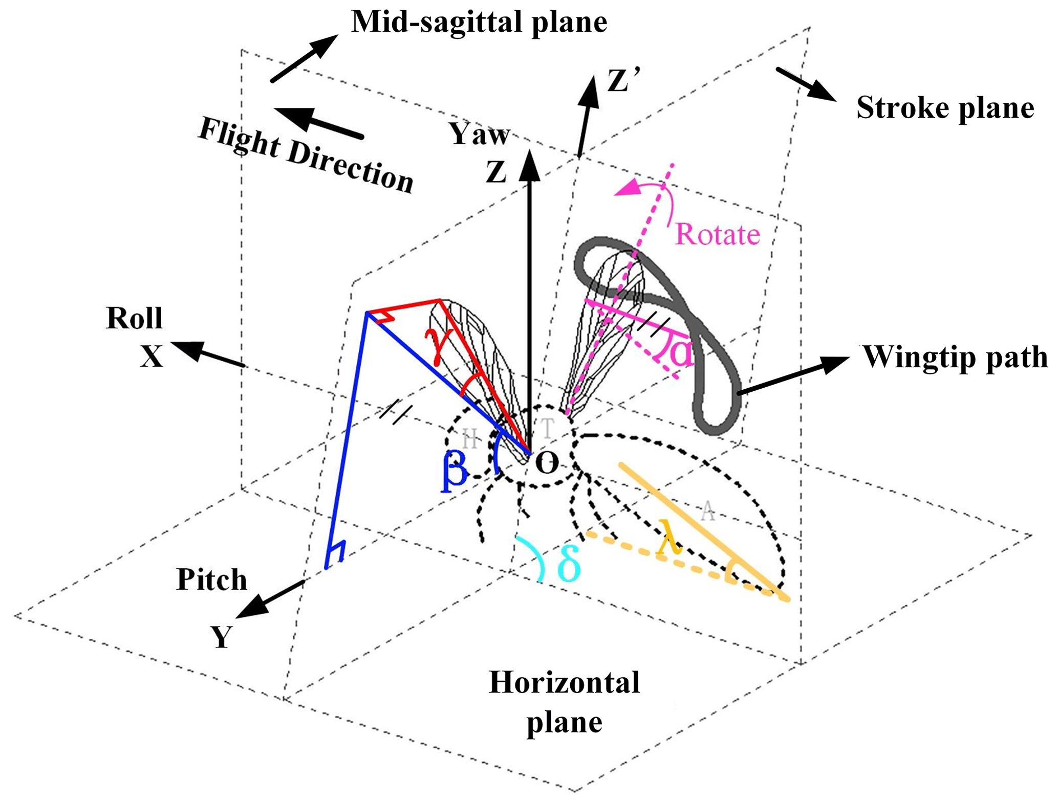
2.1 Description of flapping motion parameters
The FWMAV developed in this paper can generate three DOF motions, namely wing flapping, rotation, and sweeping passively, forming the figure eight wingtip trajectory. The wing motion parameters, including rotation angle α, flapping angle β, sweeping angle γ, and stroke angle δ, are shown in Fig. 1. The flapping angle β and sweeping angle γ are defined in the stroke plane, and the rotation angle α is defined in flight plane. Besides, the inclination angle of the body λ is the angle between the fuselage axis and the flow direction, depending on the flight altitude.
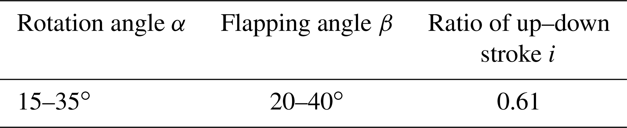
With the purpose of improving aerodynamic efficiency, the flight patterns of dragonflies and hoverflies were analyzed and optimized, and a set of suitable wing motion parameters which guided the figure eight wingtip trajectory design were obtained (Wang, 2004). The key motion parameters are shown in Table 1. Based on existing research on insect flight in nature (Young et al., 2009; Tian et al., 2013; Pelletier and Mueller, 2000; Dickinson et al., 1999), the duration of insects' upstroke is usually shorter than that of downstroke, so the flapping up and down ratio of the designed craft was set as 0.61.
2.2 Description and modeling of the mechanical structure
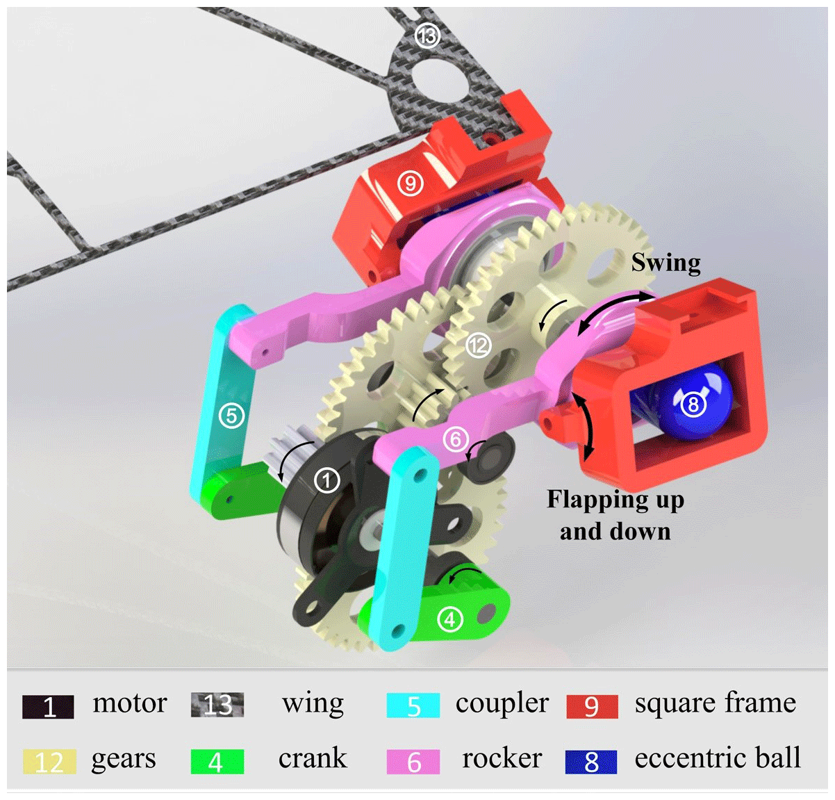
The 3D model of the innovative aircraft shown in Fig. 2 consists of a motor, a two-stage gear reducer, an eccentric ball mechanism, and an auxiliary crank rocker mechanism. A traditional, reliable commercial brushless motor (AP02; 3.1 g; 3.7 V; Xiphorix) was selected as the power source. The motor power is passed to two dynamic transmission routes. Part of the motor power is transmitted to an eccentric ball, forming the circular motion of the eccentric ball around the last stage gear shaft, by a two-stage gear reducer mechanism. The other part of motor power is responsible for driving the crank, coupler, and rocker, forming the swing motion of rocker around the same last stage gear shaft. The square frame, as the key component designed in the whole driving system, which integrates these two kinds of motion, is mounted on the rocker by the rotational joint structure, guaranteeing its swinging back and forth motion along with the rocker. Besides, the eccentric ball is equipped in the square frame. When rotates, the eccentric ball would drive the square frame swing up and down around the axis of rotational joint structure. The flapping wing would be installed on the square frame, with a simple chute structure (shown in Fig. 2). The back and forth and up and down swinging of the square frame could power the wing's twisting, swinging, and flapping motion, respectively. Thus, when the motor is activated, the wingtip forms a figure eight wingtip trajectory due to the two mechanical composite movements of the wing.
To better illustrate the FWMAV motion pattern, a kinematic mechanism is modeled in Fig. 3a. The motor is fixed to the body frame (not shown in this illustration). Shaft ML and AB obtain the same rotation speed transmitted by gears due to the same gear ratio. The sphere center of the eccentric ball, whose motion is limited by the square frame, is fixed on the point B, which connects to the output shaft AB directly. The square frame swings around the axis F1F2. When shaft AB rotates round the axis, the wing can flap from upstroke to downstroke with the square frame. The motor shaft (ML), crank (LJ), coupler (KI), and rocker (GC) make up a classic crank rocker mechanism, which provides the power to drive the wing's twisting movement with the square frame. Based on the coupling of above two kinds of mechanisms, the wing flaps and rotates around the axis F1F2 and AB, respectively, at the same time. Besides, due to the motion enlargement in the wingspan direction, the wingtip has the capability of sweeping back and forth and accomplishing the figure eight wingtip path.

Figure 3The mechanical diagram of two coupling motions. (a) The axonometric drawing of crank rocker mechanism and eccentric ball mechanism. (b) The lateral view of eccentric ball mechanical sketch. (c) The front view of crank rocker mechanical sketch.
2.2.1 Design calculation of the mechanical structure
As shown in Fig. 3b, the flapping angle β is 30∘, which means that . The angle between the initial position and horizon is set at about 40∘, so the angle between the wing connection and the edge of frame is 10∘ (). Considering the restrictions of the mechanism size and motion relationship, the radius of the ball RDE is set as 3.6 mm (RDE=3.6 mm), and the eccentricity DB is set as 2.4 mm (DB=2.4 mm). The relationship of eccentricity length (DB) and the eccentric ball radius RDE determines the flapping amplitude, which is, more exactly, the flapping angle β. Other parameters could be obtained according to basic geometric relationships. The size of the square frame can be defined according to the existing size settings.
where PT, PS are the height and length of the square frame, respectively.
Concerning the wing twist motion induced by the crank rocker mechanism, the mathematical model is established at a random position in Fig. 3c. Where L is the original point, α′ is the counterclockwise angle between LC and LJ, and α is the angle between IH and the horizon direction. The horizontal and vertical distance between points L and C is set as x and y, respectively. Then, the relationship between αand α′ can be established as follows:
According to the Eq. (3), several equations are established as the wings reach the upper and lower limit position. Then, the expressions of the upper limit torsion angle αU, the limit torsion angle αΔ, and the crank angle , when the rocker rotates from the upper limit to the lower limit, are as shown as follows:
According to the parameters in Table 1, the upper limit torsion angle αU is 15∘, and the lower limit torsion angle αΔ is 50∘. When the wing flaps the rotating angle of the eccentric ball, αLim is 224∘. The motion model is calculated by MATLAB (shown in Fig. 4a). Under this condition, the wing twists in another direction before moving to the upper or lower limit position during each stroke. This mode makes a positive lift peak at the end of each half-stroke, but it has a negative drag that adversely affects forward flight. Therefore, properly adjusting the wing rotation time by changing the rocker position relative to the wing is necessary to obtain better aerodynamic force. The optimized kinematic characteristic curve of flapping angle and rotation angle is shown in Fig. 4b. This mode has a positive peak drag, which enhances the propulsive efficiency in some ways. In addition, Fig. 4b could also show the initial parameters of the designed aircraft. As the symmetrical mode is selected, the ratio of the up–down stroke i is 0.57 according to Eqs. (4) and (7), and the lengths of JL, IJ, and CI are 10.5, 24.0, and 33 mm, respectively.
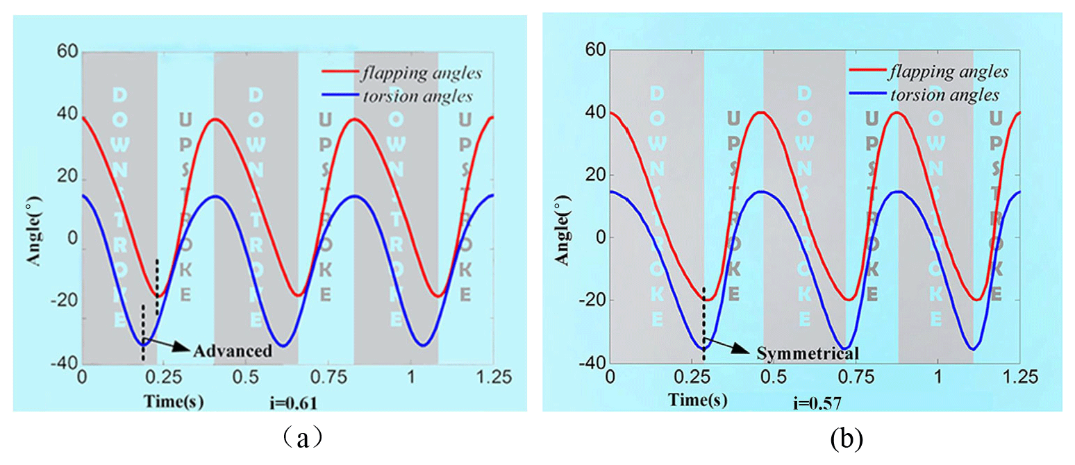
Figure 4Kinematic characteristic curve of flapping angle and rotation angle. (a) Pre-optimization simulation and (b) optimized simulation.
2.2.2 Motion parameters optimization
According to the statistical study of flying creatures (Ryan and Su, 2012; Rayner, 1979), the physical features of insects conform to the following ecologic geometry rule: wingspan and wing area are generally proportional to 1.17m0.39 and 0.16m0.72, respectively, where m is the body mass. With the increase in wing beat frequency, the size of the flapping wing creatures will decrease, scaling as 3.87m−0.33. According to existing selected components, the total mass of the FWMAV in this paper is assumed to be 25 g. Then some relevant parameters of the designed flapping wing aircraft could be obtained by referring to natural scale principle. Wingspan, wings area, and maximum flapping frequency are 27.8 cm, 113 cm2, and 13 Hz, respectively, according to the scale law principle. However, the relationship between the wing area and the mass of FWMAV is usually not completely consistent with the scale law principle. If designed according to the scale law, the wing area produces a small lift force. Thus, it is necessary to adjust the wingspan and wing area to 28 cm and 139 cm2 in the following design process. Considering the motion parameter of a flapping wing, the risk of wing frame structure failure induced by high flapping frequency should not be overlooked. Therefore, maximum flapping frequency is a very important reference when selecting the motor power and wing frame stiffness.
2.2.3 Fabrication and assembly of the mechanical structure
The assembly drawing of FWMAV, named Type I, is shown in Fig. 5. In order decrease the aircraft's mass and increase the total stability, carbon fiber material was chosen to fabricate the fuselage and empennage with computer numerical control (CNC) machining (JingYan Instrument Company; CNC4030). Considering the unique size and shape and strength and stiffness requirement, the key parts of the flapping mechanism, eccentric ball, and square frame were fabricated by 3D ABS (acrylonitrile butadiene styrene) photopolymer digital printing. Friction is always a tough problem for moving components, especially because the FWMAV's battery life is restricted by the aircraft weight limitation. To reduce the friction between movement components, strengthening treatment was applied to the movement component surface of the eccentric ball and the square frame. Carbon fiber material was adopted as the wing vein material to withstand high flapping frequency oscillation without breakdown. The wing was fixed on the upper surface of square frame with a simple chute structure and three screws. The 60 µm thick polyester film was selected as the wing skin due to the characteristic of appropriate flexibility. The mass of the aircraft and key parts are shown in Table 2.
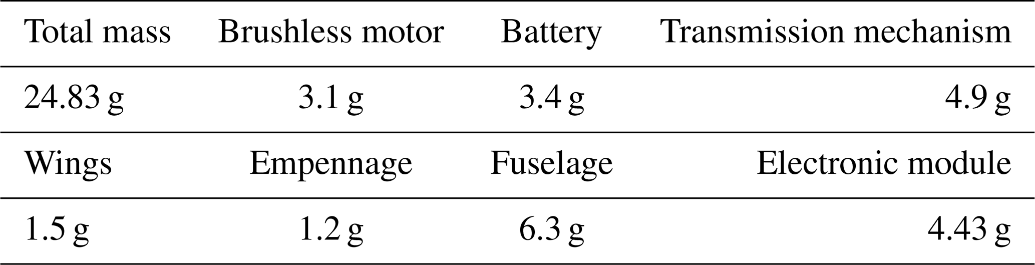
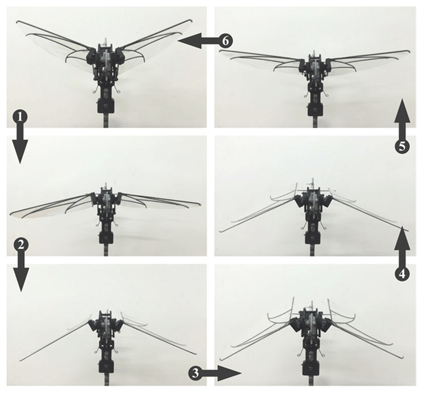
Figure 6a describes the wingtip trace of the designed flapping wing aircraft by SolidWorks, and Fig. 6b is a cross section of the wing of the whole flapping cycle. Obviously, the wingtip trajectory is a figure eight, and the wing can realize rotation and sweep motion in the flapping process. Figure 7 shows the whole front view flapping cycle of the FWMAV in this paper.
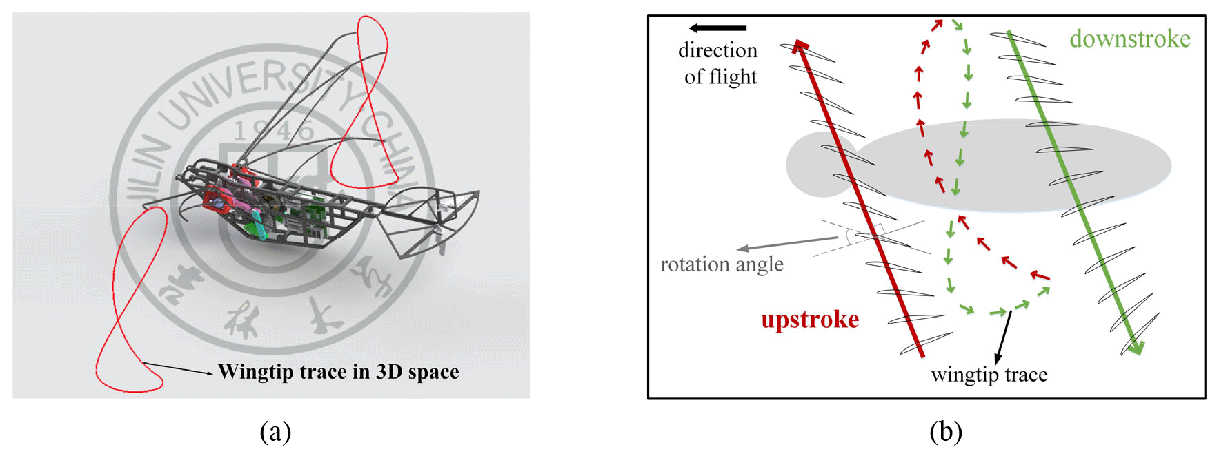
Figure 6Simulating diagram of FWMAV movement. (a) Wingtip path of figure eight with SolidWorks. (b) Wing cross section in a lateral view at various instances.
The aerodynamic forces obtained in the experiment are the most convincing data to reflect an aircraft's aerodynamic performance. In this paper, the horizontal and vertical forces acquired by the data acquisition system could be viewed as being the total thrust and lift, respectively, without considering the inertia and vibration force effect generated by the mechanism motion during flight test (Lobontiu and Garcia, 2003; Syaifuddin et al., 2006). The horizontal force and vertical forces of the aircraft were directly measured by a self-developed force balance, which was designed based on linear deformation theory (shown in Fig. 8).
3.1 Experiment equipment introduction
The testing system consists of a control and display system, data acquisition system, and data processing system (shown in Fig. 8). The FWMAV is fixed on the force measuring device when tested in the wind tunnel, and the flapping frequency controlled by the motor is recorded by the frequency indicator. According to existing research (Pérez-Arancibia et al., 2011), the total lift force for a FWMAV has directly close relationship with the wing flapping frequency and stroke amplitude. As a result, the flapping frequency is a very important variable in the aerodynamic force measurement experiment. The cross section dimension of the wind tunnel test section is 0.4 m×0.4 m, and the wind speed range is 0–13 m s−1 as measured by an anemometer. The experiment in the paper was conducted on the condition that the aircraft was faced with a low upwind wind velocity so that the small wind tunnel could meet the present test requirements. The force measuring device to test the FWMAV gentle forces relies on the designed flexure hinge structure which would be equipped with two force sensors (Kistler; type 9211B) during the experiment. The force signal was recorded through a programmable multi-axis controller (PMAC) and stored in the host computer. More details about the system parameters are shown in Table 3.
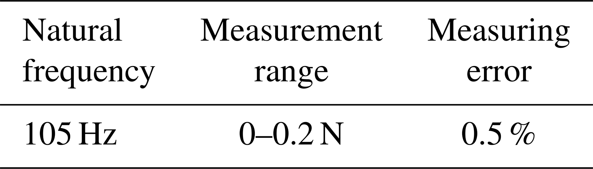
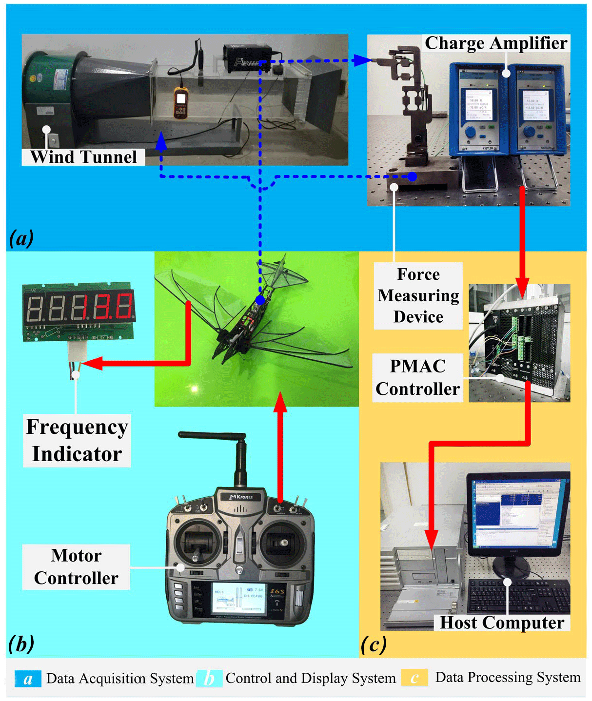
Figure 8Procedure chart of the flapping test. (a) The data acquisition system consists of a wind tunnel, a force measuring device, and the charge amplifiers. (b) The control and display system consists of a motor controller and the frequency indicator. (c) The data processing system consists of a PMAC controller and a host computer.
3.2 Wing design and aerodynamic tests
Except for the certain flapping mechanical structure and driven actuator, the wing is the also a very vital component that affects the aerodynamic forces for the whole aircraft. Apart from the wing shape and size, the stiffness would also determine the aerodynamic forces characteristic to some degree. Flapping insects obviously have flexible wing deformation during flight, which increases their flight stability and saves energy consumption (Wootton, 1992; Wei et al., 1999). For an artificial flapping wing aircraft, wing flexibility would also improve aerodynamic forces characteristics (Pornsin-Sirirak et al., 2001). Actually, the wing has limited flexibility induced by the material characteristic of wing skin film and wing vein material. These factors have little effect on the whole wing flexibility compared to that of wing vein layout and wingspan length, and it is hard to obtain quantitative relationships and the desired wing flexibility. By adjusting the wing vein size, it could change the wing flexibility according to classical calculating formula of the moment of inertia of the beam structure. A series of aerodynamic forces experiment were conducted with flexible wings.
3.2.1 Wing bending stiffness design
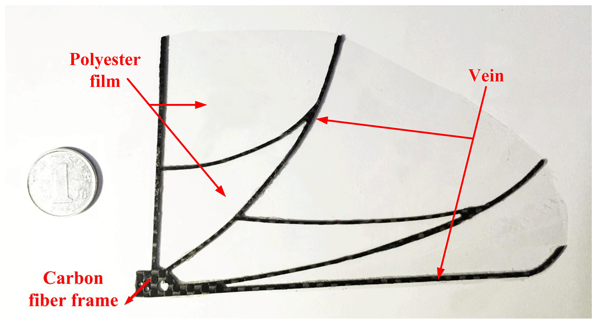
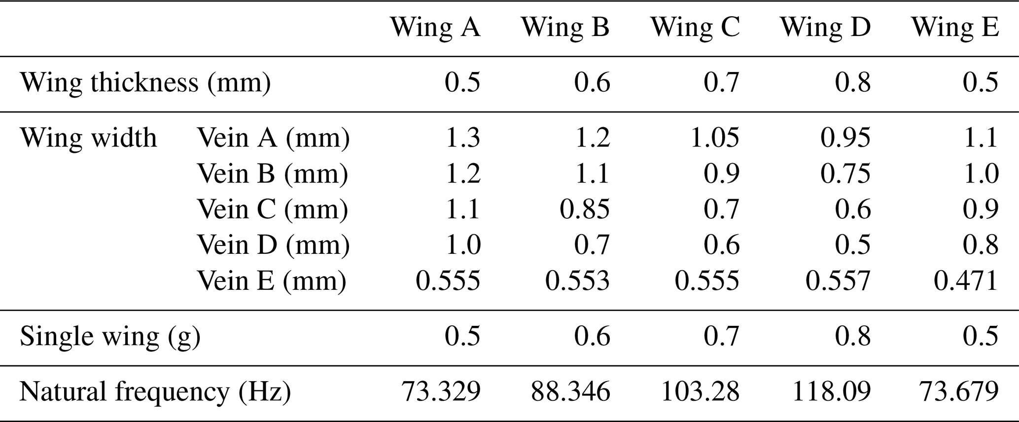
Carbon fiber was selected and designed as the supporting part of the wings. The bending stiffness of the wing can be changed by adjusting the width and thickness of the carbon fiber frame. In order to select a suitable wing for the new aircraft, five wings with different vein thickness and width sizes were designed and marked as wing A, wing B, wing C, wing D, and wing E, respectively. These wings had the same vein layout and overall size design (shown in Fig. 9) inspired by the fruit fly wing (Hassanalian et al., 2017; Meng and Sun, 2016). The flapping wing can be simplistically viewed as a cantilever beam vibration. The bending stiffness is determined by the moment of inertia of the frame, which is more sensitive to the wing thickness than the wing width, according to the classical calculating formula for the moment of inertia of beam structure. Modal analysis was adopted by Ansys to analyze the rationality of the wing stiffness division. The structure parameters of five different wings are shown in Table 4. It could be seen that the value of natural frequency of wings A and E were very similar, and the natural frequency increased gradually from wings A to D, which was mainly due to the gradual increase in the wings' thickness. The width of the wing frame had less of an effect on the stiffness of the wing compared with thickness.
3.2.2 Aerodynamic test of different types of wing
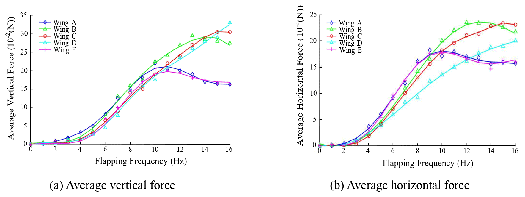
In this paper, the aircraft is designed with the maximum flapping frequency of 13 Hz. In order to select the matched stiffness of the wing which could produce the best aerodynamic effect, the maximum flutter frequency was adjusted to 17 Hz by adopting a larger actuator voltage within a short time. In this experiment, the average aerodynamic force of five groups of different wing stiffness vs. flapping frequency was tested when the wind speed was 3 m s−1 and the range of the flapping frequency was 0 to 16 Hz.
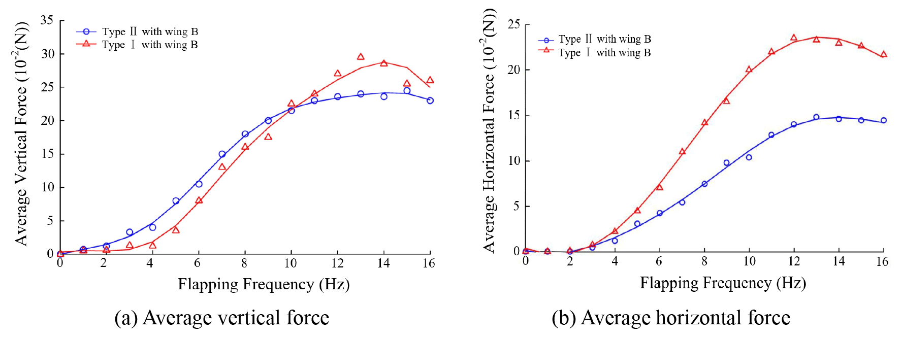
Figure 10 shows the test results of the average vertical force and average horizontal force of the five different types of wing. It could be seen that the vertical force and the horizontal force have the same variation trend with the increase in flapping frequency. There were some obvious similarities between wing A and wing E in the maximum average vertical force, maximum average horizontal force, and the variation trend. When flapping frequency exceeded the specific value, the aerodynamic forces had the trend of decreasing. This was because the wing cannot finish the effective flutter deformation in the flapping cycle at a high flapping frequency. Through the comparison of wings B, C, and D of the vertical force, it was found that wings B and C had the average force peak at 14 and 15 Hz, respectively, and the vertical force of wing D always increased within the flapping frequency range. The horizontal force of these types of wings showed the same trend with the frequency variation. The reason for this phenomenon was that with the increase in wing stiffness, the wing needed a higher flutter frequency to match the maximum effective deformation for higher lift. When the flapping frequency was low, the variation in lift and thrust vs. flapping frequency had a similar trend and value, which meant that the stiffness of the wings was not the key factor in affecting the aerodynamic forces in the low-frequency phase. According to the test results, for a certain wing, it has the maximum effective wing deformation during flapping which can generate maximum lift according to the flapping frequency. This flapping frequency could be named the best flutter frequency (BFF), which has close relationship with wing stiffness. Under BFF, the smaller wing stiffness is, the higher the lift that would be obtained. Therefore, a wing with suitable bending stiffness should be carefully designed for a FWMAV. In this paper, wing B was the most suitable wing because it had the best aerodynamic forces among several types of wings, which meant a 28 g vertical average force and a 23 g horizontal average force at 13 Hz flapping frequency.
3.3 Aerodynamic test of FWMAV with different motion pattern
More experiments were carried out to test the aerodynamic performance of the FWMAV with wing B. In order to study the effect of wing twisting and swinging motion on aerodynamic forces, the flapping wing aircraft which only had the up and down flapping pattern was needed to conduct a comparative experiment. Generally speaking, this one DOF flapping wing aircraft of the control group should keep the same parameters as that of a multi-DOF aircraft as much as possible, except for the motion pattern. Along this line of thinking, it is the best choice to select the experimental aircraft itself as the control group target. Under this condition, the influencing factors of fuselage weight, center of gravity position, wing attitude, and others which could change the aerodynamic force value would not exist in the experiment. Considering that the aircraft's driving system's mechanical structure drove the wing's twisting and swinging motions with the square frame powered by the crank ➃, rocker ➄, and rocker ➅ shown in Fig. 2, it did offer an opportunity to modify the multi-DOF mechanism to a single-DOF one by breaking these links in power transmission without any effect on the flapping wing motion. In the experiment preparation phase, the coupler ➄ was removed, and the rocker ➅ was fixed on the fuselage where rocker ➅ has a 15∘ angle with a horizontal direction, so there was a 15∘ attack angle for the single-DOF flapping wing aircraft. The aircraft that could only flap up and down, without a twisting and swinging motion, was named Type II, and the aircraft with a wing twisting and swinging motion was named Type I.
Figure 11 shows the aerodynamic forces of two different types vs. the flapping frequency obtained in a series of experiments. In Fig. 11a, it was obvious that the average vertical force of Type I was somewhat smaller than that of Type II when the flapping frequency was below the critical frequency (10 Hz). As the frequency increased to 11 Hz, the average lift of Type I exceeded that of Type II at a rapid rate. The maximum average vertical forces of Type I and Type II were 27 and 22 g, respectively, when the flapping frequency was about 13 Hz. In fact, the total average vertical force or lift consisted of a static lift and a kinematic lift. The static lift was the vertical force induced by wind speed, and it is a complex function of the wing area, wing flexibility, attack angle, etc. The kinematic lift was caused by flapping kinematics and wing deformation, which both have positive correlations with the flapping frequency. Combining the experimental result, it could be found that the static lift had a predominant role in vertical force generation in the low flapping frequency phase. When the flapping frequency increased, the kinematic lift was induced by the wing's twisting and swinging motions, and the deformation was passively strengthened, resulting in the average lift of the Type II aircraft exceeding Type I when the flapping frequency was large enough.
The average horizontal force or thrust of these two types of aircraft had a similar variation trend in that both the average thrust increased with the incremental increase in flapping frequency. When the flapping frequency increased to the specific value (13 Hz), the average thrust stopped increasing gradually. Once the frequency exceeded the specific value, the average thrust began to decrease slowly. It should be mentioned that the average thrust of the Type II aircraft was always larger than that of Type I at the same frequency condition. By analyzing the experimental result, it is seen that the wing with the twisting and swinging motion obviously did have a thrust improving effect. The maximum average thrust force of Type I and Type II could be up to 23 and 14 g, approximately, and the average thrust force of Type II was improved by 64.3 % compared to that of Type I. When the flapping frequency was too large, the wing could not finish the desired deformation in a rapid flapping cycle, which adversely affected the interaction between the wing foil and air flow. Thus, the average thrust and lift both began a decreasing trend.
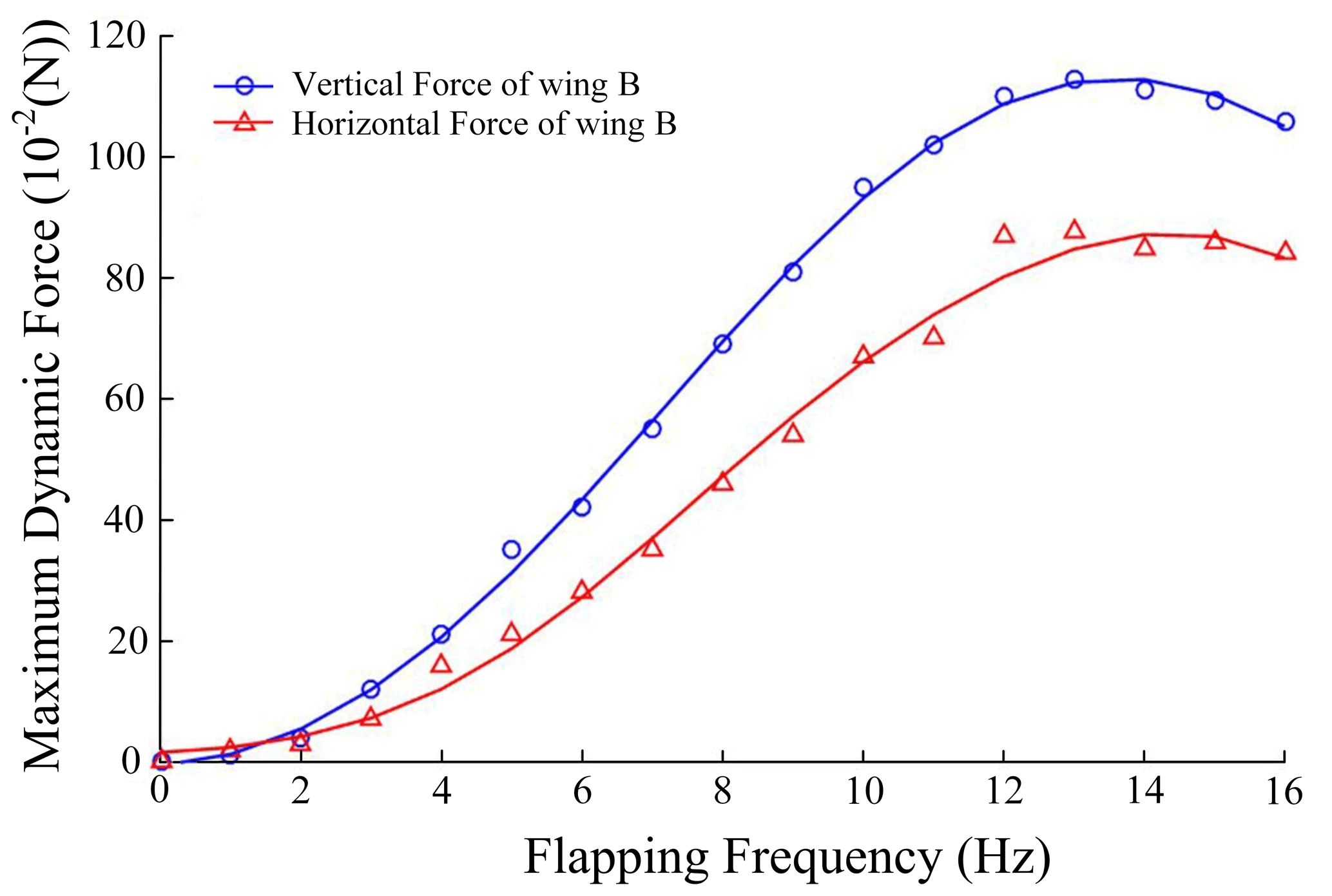
Figure 12 shows the maximum aerodynamic forces vs. the flapping frequency. The maximum vertical force could be up to 115 g at 13 Hz, and the horizontal aerodynamic peak value is about 80 g. The thrust–weight ratio, which is defined as the ratio of the maximum thrust vs. gravity generated during the flight, is an important indicator for measuring the maneuverability of an aircraft. Normally, civil airplanes have a thrust–weight ratio of 0.2, approximately, in the takeoff stage, while the flapping wing aircraft designed in this paper has a propulsion ratio of 0.926, which means good maneuverability performance.
An innovative flapping wing micro aerial vehicle which could achieve complex composite motions of flapping, twisting, and swinging motions, forming figure eight wingtip trajectory, was presented in this paper. Along with the design concept of reducing any possible weight and size, the total mass and wingspan of the aircraft was about 25 g and 28 cm, respectively, with classical and reliable mechanical components. Through a series of aerodynamic force experiments, it was found that the average lift and thrust of the designed aircraft was 27 and 23 g at a 13 Hz operating flapping frequency, which was sufficient to drive the flapping wing vehicle in theory. Normally, the aerodynamic characteristics would be improved with the increase in flapping frequency, but the improvement induced by the flapping frequency increase had a limit due to the critical frequency determined by the wing stiffness. Besides, by analyzing the data obtained from the measuring system, it was found that the FWMAV, with a complex figure eight wingtip trajectory, did have a better aerodynamic efficiency than an up-and-down flapping FWMAV, due to the aerodynamic enhancement induced by the wing's twisting and swinging motion, while the weight increase induced by more mechanical components applied to enhance the bionic level adversely impacted on the aerodynamic performance. It was still heavy for the FWMAV in this paper, and the carbon fiber material used in massive quantities for airframe structure should have better substitutes. For traditional mechanism structure flapping wing vehicles, the overall aerodynamic performance is very sensitive to weight, let alone the flying endurance ability. As a result, an increase in unit mass would make the quantitative improvement in the aerodynamic forces very hard to identify. The cost-effectiveness ratio between the weight increase and aerodynamic efficiency improvement needs further studies, and it may be a new reference in the process of micro aircraft design.
The data in this study can be requested from the corresponding author.
SJ and YH designed the aircraft. QL and LM organized and structured the paper. YW and XZ designed the experiment and did the test. QL reviewed the paper and gave constructive suggestions for improving the whole process.
The authors declare that they have no conflict of interest.
The authors are grateful to the financial support from the National Nature Science Foundation of China (NSFC; grant nos. U1601203 and U19A20104), the Jilin Province Science and Technology Development Program (grant nos. 20180101321JC and 20190302099GX), the Jilin Province Industrial Technology of Research and Development (grant no. 2019C037-3), and the Science and Technology project of Jilin Provincial Department of Education (grant no. JJKH20200955KJ).
This research has been supported by National Nature Science Foundation of China (NSFC; grant nos. U1601203 and U19A20104), the Jilin Province Science and Technology Development Program (grant nos. 20180101321JC and 20190302099GX), the Jilin Province Industrial Technology of Research and Development (grant no. 2019C037-3), and the Science and Technology project of Jilin Provincial Department of Education (grant no. JJKH20200955KJ).
This paper was edited by Daniel Condurache and reviewed by two anonymous referees.
Banala, S. K. and Agrawal, S. K.: Design and optimization of a mechanism for out-of-plane insect winglike motion with twist, J. Mech. Design, 127, 841–844, https://doi.org/10.1115/1.1924474, 2005.
Bolsman, C. T.: Flapping wing actuation using resonant compliant mechanisms, An insect-inspired design, TU Delft, Delft University of Technology, Delft, 2010.
Conn, A., Burgess, S., and Hyde, R.: From natural flyers to the mechanical realization of a flapping wing micro aerial vehicle, in: 2006 IEEE international conference on robotics and biomimetics, IEEE, 17–20 December 2006, Kunming, China, 439–444, 2006.
Dickinson, M. H., Lehmann, F. O., and Sane, S. P.: Wing rotation and the aerodynamic basis of insect flight, Science, 284, 1954, https://doi.org/10.1126/science.284.5422.1954, 1999.
Fenelon, M. A. A. and Furukawa, T.: Design of an active flapping wing mechanism and a micro aerial vehicle using a rotary actuator, Mech. Mach. Theory, 45, 137–146, 2010.
Hassanalian, M., Throneberry, G., and Abdelkefi, A.: Wing shape and dynamic twist design of bio-inspired nano air vehicles for forward flight purposes, Aerosp. Sci. Technol., 68, 518–529, 2017.
Keennon, M. T. and Grasmeyer, J. M.: Development of the Black Widow and Microbat MAVs and a Vision of the Future of MAV Design, in: AIAA/ICAS International Air and Space Symposium and Exposition: The Next, 100, 14–17, 2003.
Liu, Q., Li, Q., Zhou, X., Xu, P., Ren, L., and Pan, S.: Development of a novel flapping wing micro aerial vehicle with elliptical wingtip trajectory, Mech. Sci., 10, 355–362, https://doi.org/10.5194/ms-10-355-2019, 2019.
Lobontiu, N. and Garcia, E.: Analytical model of displacement amplification and stiffness optimization for a class of flexure-based compliant mechanisms, Comput. Struct., 81, 2797–2810, https://doi.org/10.1016/j.compstruc.2003.07.003, 2003.
McIntosh, S. H., Agrawal, S, K., and Khan, Z.: Design of a Mechanism for Biaxial Rotation of a Wing for a Hovering Vehicle, IEEE-ASME T. Mech., 11, 145–153, https://doi.org/10.1109/TMECH.2006.871089, 2006.
Meng, X. and Sun, M.: Wing kinematics, aerodynamic forces and vortex-wake structures in fruit-flies in forward flight, J. Bionic Eng., 13, 478–490, 2016.
Nguyen, Q. V., Park, H., and Byun, D.: Recent progress in developing a beetle-mimicking flapping-wing system, in: World Automation Congress (WAC), IEEE 2010, 19–23 September 2010, Kobe, Japan, 1–6, 2010.
Pelletier, A. and Mueller, T. J.: Low Reynolds number aerodynamics of low-aspect-ratio, Thin/flat/cambered-plate wings, J. Aircraft, 37, 825–832, 2000.
Pérez-Arancibia, N. O., Ma, K. Y., Galloway, K. C., Greenberg, J. D., and Wood, R. J.: First controlled vertical flight of a biologically inspired microrobot, Bioinspir. Biomim., 6, 036009, https://doi.org/10.1088/1748-3182/6/3/036009, 2011.
Peters, H. J., Goosen, J. F. L., and Van, K. F.: Methods to actively modify the dynamic response of cm-scale FWMAV designs, Smart Mater. Struct., 25, 055027, https://doi.org/10.1007/s00542-015-2762-6, 2016.
Pornsin-Sirirak, T. N., Tai, Y. C., Ho, C. M., and Keennon, M.: Microbat: a palm-sized electrically powered ornithopter, in: Proceedings of the Nasa/jpl Workshop on Biomorphic Robotics, 2001.
Ramasamy, M., Leishman, J. G., and Lee, T. E.: Flowfield of a rotating-wing micro air vehicle, J. Aircraft, 44, 1236–1244, https://doi.org/10.2514/1.26415, 2007.
Rayner, J. M. V.: A new approach to animal flight mechanics, J. Exp. Biol., 80, 17–54, 1979.
Ryan, M. and Su, H. J.: Classification of flapping wing mechanisms for micro air vehicles, in: ASME 2012 International Design Engineering Technical Conferences and Computers and Information in Engineering Conference, American Society of Mechanical Engineers, 12–15 August 2012, Chicago, Illinois, USA, 105–115, https://doi.org/10.1115/DETC2012-70953, 2012.
Shyy, W., Lian, Y., and Tang, J.: Aerodynamic of Low Reynolds Number flyers, Cambridge University Press, UK, 2008.
Shyy, W., Aono, H., and Chimakurthi, S. K.: Recent progress in flapping wing aerodynamics and aeroelasticity, Prog. Aerosp. Sci., 46, 284–327, https://doi.org/10.1016/j.paerosci.2010.01.001, 2010.
Syaifuddin, M., Park, H. C., and Goo, N. S.: Design and evaluation of a LIPCA-actuated flapping device, Smart Mater. Struct., 15, 1225, https://doi.org/10.1088/0964-1726/15/5/009, 2006.
Tian, F. B., Luo, H., and Song, J.: Force production and asymmetric deformation of a flexible flapping wing in forward flight, J. Fluid. Struct., 36, 149–161, https://doi.org/10.1016/j.jfluidstructs.2012.07.006, 2013.
Wang, Z. J.: The role of drag in insect hovering, J. Exp. Biol., 207, 4147–4155, https://doi.org/10.1242/jeb.01239, 2004.
Wei, S., Berg, M., and Ljungqvist, D.: Flapping and flexible wings for biological and micro air vehicles, Prog. Aerosp. Sci., 35, 455–505, https://doi.org/10.1016/S0376-0421(98)00016-5, 1999.
Wootton, R. J.: Functional Morphology of Insect Wings, Annu. Rev. Entomol., 37, 113–140, https://doi.org/10.1146/annurev.en.37.010192.000553, 1992.
Young, J., Walker, S. M., and Bomphrey, R. J.: Details of insect wing design and deformation enhance aerodynamic function and flight efficiency, Science, 325, 1549–1552, https://doi.org/10.1126/science.1175928, 2009.