the Creative Commons Attribution 4.0 License.
the Creative Commons Attribution 4.0 License.
 | 01 Jun 2021
Analysis of the shift quality of a hydrostatic power split continuously variable cotton picker
Wanqiang Chen
Zhaorui Xu
Yeqi Wu
Yehui Zhao
Maohua Xiao
In order to improve the ride comfort of a continuously variable cotton picker, the shift quality of the cotton picker is analysed. Firstly, the transmission principle of the hydrostatic power split continuously variable transmission (CVT) with a single planetary gear set is introduced; secondly, the shift dynamic model of the power train is constructed, and the key models are verified by experiments; finally, the influence law and mechanism of various factors in the shift qualities of a cotton picker are analysed. The results show that the increase in main circuit pressure will reduce the shift quality of the cotton picker; the influence of clutch-charging flow and acceleration rate on the shift quality of the cotton picker can be ignored; with the action time of the clutch delayed in a certain range, the shift impact first decreases slightly, then increases, and finally decreases; the increase in the cotton box weight can slightly improve the shift quality of the cotton picker but is at the cost of consuming more clutch-sliding energy. If different factors are evaluated together, the value of the main circuit pressure and charging flow should not be too large or too small. At the same time, the action time of a clutch to be disengaged should be delayed, and the action time of a clutch to be engaged should be advanced. The conclusions of this study can provide theoretical support for the controller development of a continuously variable cotton picker.
- Article
(6479 KB) - Full-text XML
- BibTeX
- EndNote


The working condition of the cotton picker is complex, and its working load is not stable (Kazama et al., 2018; Delhom et al., 2019). In recent years, hydrostatic continuously variable transmission (CVT) has been applied in cotton pickers, which can realize constant power output of an engine through load-adaptive control so as to ensure the stability of a working system. However, hydrostatic CVT has low transmission efficiency and high energy consumption, resulting in poor fuel economy. Hydrostatic power split CVT combines the advantages of mechanical CVT and hydrostatic CVT. It has good power performance and fuel economy (İnce and Güler, 2020; Rotella and Cammalleri, 2018; Zeman et al., 2017; Li et al., 2020), making it an ideal transmission system of a cotton picker. Since Fendt presented the first hydrostatic power split CVT for its 926 “Vario” tractor in 1996, this kind of transmission has been gradually applied to various agricultural vehicles (Dam et al., 2020). However, due to the performance limitation of swash plate axial piston units, most of the current hydrostatic power split CVT has to set multiple ranges to limit the energy consumption caused by parasitic power in each range. For example, “Eccom” developed by ZF, “S-Matic” developed by Steyr and “AutoPowr” developed by John Deere all have at least two ranges (Renius and Resch, 2005; Renius, 2020). The introduction of multi-range technology in CVT has brought the problem of power shift, so it is necessary to control the shift quality of agricultural vehicles (Zhu et al., 2016). In order to solve this problem, structural optimization and software optimization are usually used. The way to optimize the structure is to use different planetary gear sets alternately in different ranges, so that the CVT has the same transmission ratio before and after a shift without changing the displacement of a variable pump. This method avoids the operation of swash plate axial piston units in the shift process but only involves the control of wet clutches. Different from structure optimization, the purpose of software optimization is to obtain the best matching law of control parameters of a wet clutch (Iqbal et al., 2015; Yu et al., 2020). Generally speaking, using multiple planetary gear sets alternately can obtain better shift quality, but it leads to complex transmission structure, which is not suitable for cotton pickers. Therefore, a hydrostatic power split CVT with a single planetary gear set for a cotton picker is proposed in this paper. Although the structure of the transmission is simple, it needs to control the variable pump and wet clutch at the same time when shifting. In order to improve the shift quality of the cotton picker, the influence mechanism of various parameters on the shift quality is studied in this paper.
The principle of the CVT is shown in Fig. 1. In the forward direction, the transmission has a direct range R0 for starting, a power split range R1 for low-speed driving and a power split range R2 for high-speed driving.
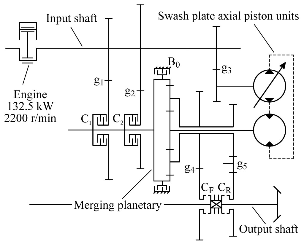
When the transmission works in range R0, adjust the displacement of the variable pump to 0 and engage the brake B0 before starting. Then, gradually increase the displacement of the variable pump to increase the speed of the output shaft. In range R0, engine power is transmitted to output shaft through input shaft, gear pair g3, swash plate axial piston units, planetary gear set, gear pair g4 and clutch CF in turn.
When the running speed of the cotton picker reaches the required speed of range R1, separate brake B0, engage clutch C1, and quickly adjust the displacement of the variable pump in the reverse direction so as to shift the range from R0 to R1. After that, gradually increasing the displacement of the variable pump, the cotton picker will continue to accelerate. Similarly, when the running speed of the cotton picker reaches the required speed of range R2, separate clutch C1, engage clutch C2, and quickly adjust the displacement of the variable pump in the reverse direction so as to shift the range from R1 to R2. In range R1 or R2, the engine power is divided into two parts on the input shaft: one part is transmitted to the sun gear via the gear pair g3 and the swash plate axial piston units and the other part is transmitted to the ring gear via the gear pair g1 (or g2) and clutch C1 (or C2). The two parts of power are merged in the planetary gear set and transmitted to the output shaft through the carrier, gear pair g4 and clutch CF.
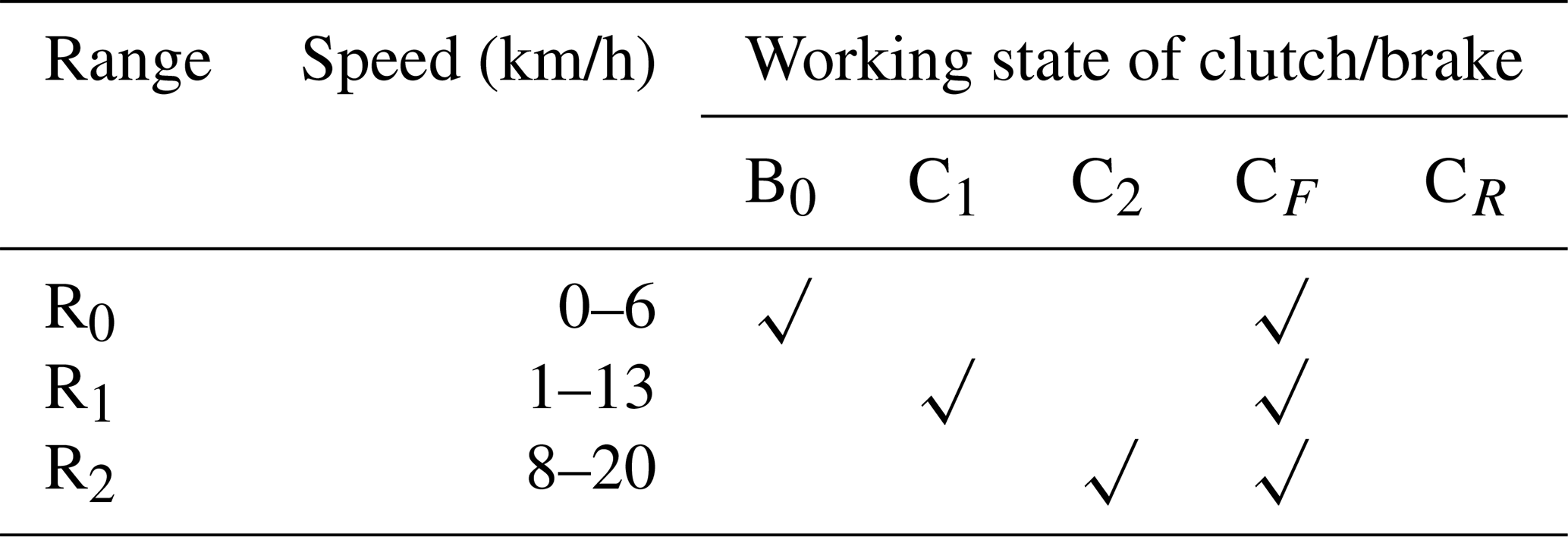
The tractor speed and clutch schedule at the rated engine speed are shown in Table 1.
Table 1Clutch/brake schedule of the cotton picker in the forward direction.
Consider that the speed of each shaft of the planetary gear set satisfies the equation
where ns, nr and nc are the rotation speed of the sun gear, the ring gear and the carrier of the planetary gear set, respectively, r/min; p is the standing ratio of the planetary gear set.
The rotation speed of the motor and pump meets the following relationship:
where nm and np are the rotational speed of the constant displacement motor and the variable displacement pump, respectively, r/min; ε is the ratio of pump displacement to motor displacement.
It is easy to deduce the transmission ratio in each range as follows:
where ) is the transmission ratio of the CVT in range Rx; ix is the transmission ratio of the gear pair gx.
On this basis, the running speed of the cotton picker in each range can be obtained according to the following equation:
where is the running speed of the cotton picker in range Rx, km/h; ne is the rotation speed of the engine, r/min; rd is the dynamic radius of the driving wheel, m; ir is the transmission ratio of the driving axle.
Substituting Eq. (3) into (4) and considering , the speed regulation range of range R1 and range R2 is obtained as follows:
where is the speed regulation range of the cotton picker in range Rx, km/h. According to Eq. (6), . Therefore, the speed regulation range of the transmission is equal in each range, which is suitable for a cotton picker with low running speed.
3.1 Swash plate axial piston units
Swash plate axial piston units are composed of a variable displacement pump and a constant displacement motor, which is the core speed regulation component of the hydrostatic power split CVT. The variable displacement pump transforms mechanical energy into pressure energy, while the constant displacement motor converts pressure energy into mechanical energy. The pressure, flow, torque and rotation speed of the variable pump meet the following relations:
where pp and pm are the inlet and outlet pressure of the pump and motor, respectively, MPa; Qp and Qm are the inlet and outlet flow of the pump and motor, respectively, L/min; Tp and Tm are the theoretical torque of the pump and motor, respectively, N ⋅ m; Vp and Vm are the rated displacement of the pump and motor, respectively, cm3/r.
Due to the high energy consumption of the hydraulic system, the friction and leakage of the pump and motor need to be considered (ITI GmbH, 2012):
where Tfp and Tfm are the friction torque of the pump shaft and motor shaft, respectively, N ⋅ m; ηmp and ηmm are mechanical efficiency of the pump and motor, respectively; Qlp and Qlm are the leakage flow of the pump and motor, respectively, L/min; ηvp and ηvm are the volumetric efficiency of the pump and motor, respectively.
Since the motor needs to accelerate in reverse when the transmission is shifting, the dynamic response of the swash plate axial piston units should be considered in modelling. According to previous studies (Yuan et al., 2008; ITI GmbH, 2012), the response of a pump displacement-regulating mechanism can be regarded as a second-order system; the response of the motor to pump displacement can be regarded as a second-order system; the response of the electronic control system can be regarded as a first-order system. Therefore, the swash plate axial piston units can be regarded as a fifth-order system, and its transfer function is as follows:
where G(s) is the transfer function of the displacement-regulating mechanism of the pump; b1–b5 are constants and have different values in different motor rotation directions, which can be obtained by system identification (Maier et al., 2019; Karagoz and Batselier, 2020).
3.2 Gear and shaft
The relationship between the speed and torque of a standard gear is as follows:
where i12 is the transmission ratio of the meshing gear pair; n1 and n2 are the rotational speed of the driving gear and driven gear, respectively, r/min; T1 and T2 are the torque of the driving gear and the driven gear, respectively, N ⋅ m.
The rotation speed of each shaft of the planetary gear set can be determined by Eq. (1), and the torque of each shaft satisfies the following equation:
where Ts, Tr and Tc are the torque of the sun gear, ring gear and carrier of the planetary gear set, respectively, N ⋅ m.
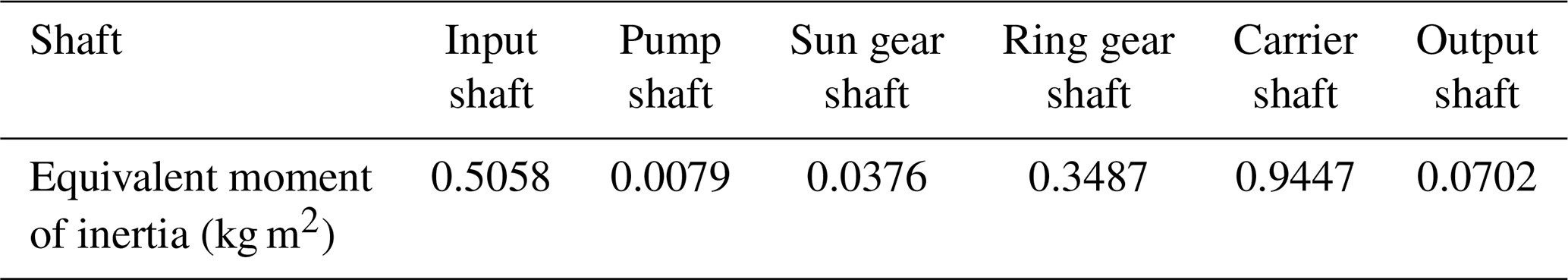
The moment of inertia of the gear and shaft is obtained by Solidworks, while the moment of inertia of the clutch and other parts is provided by the manufacturer. The moment of inertia of all the parts is equivalent to the transmission shaft based on the transmission ratio. On this basis, the moment of inertia of each shaft will produce additional dynamic torque during the shift process:
where Ta and T0 are the actual and theoretical torque of the shaft, respectively, N ⋅ m; J is the moment of inertia of the shaft, kg m2; ω is the angular velocity of the shaft, rad/s; t is the time, s.
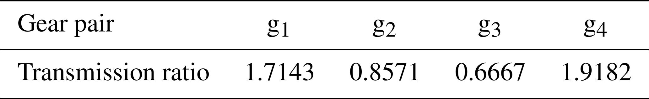
The transmission ratio of each gear pair and the equivalent moment of inertia of each shaft are shown in Tables 2 and 3, respectively.
3.3 Wet clutch
The sliding torque of the wet clutch is calculated as follows (Wang et al., 2020):
where Tf is the sliding torque of the friction discs, N ⋅ m; nf is the number of friction surfaces; μ is the actual friction coefficient of the friction disc; ro and ri are the outer radius and inner radius of the friction disc, mm; FN is the normal force on the clutch friction disc, N; Δω is the average speed difference over the friction disc, r/min; μ0 and μs are the sticking friction coefficient and sliding friction coefficient between the friction discs of the clutch, respectively; M1–M3 are constants related to the material of the friction disc; pc is the oil pressure, MPa; AP is the effective area of the clutch piston, mm2; k is the stiffness of the clutch return spring, N/mm; x0 and x are the initial and current displacements of the return spring, mm; FS is the friction resistance of the clutch piston when moving, N.
3.4 Power train of the whole machine
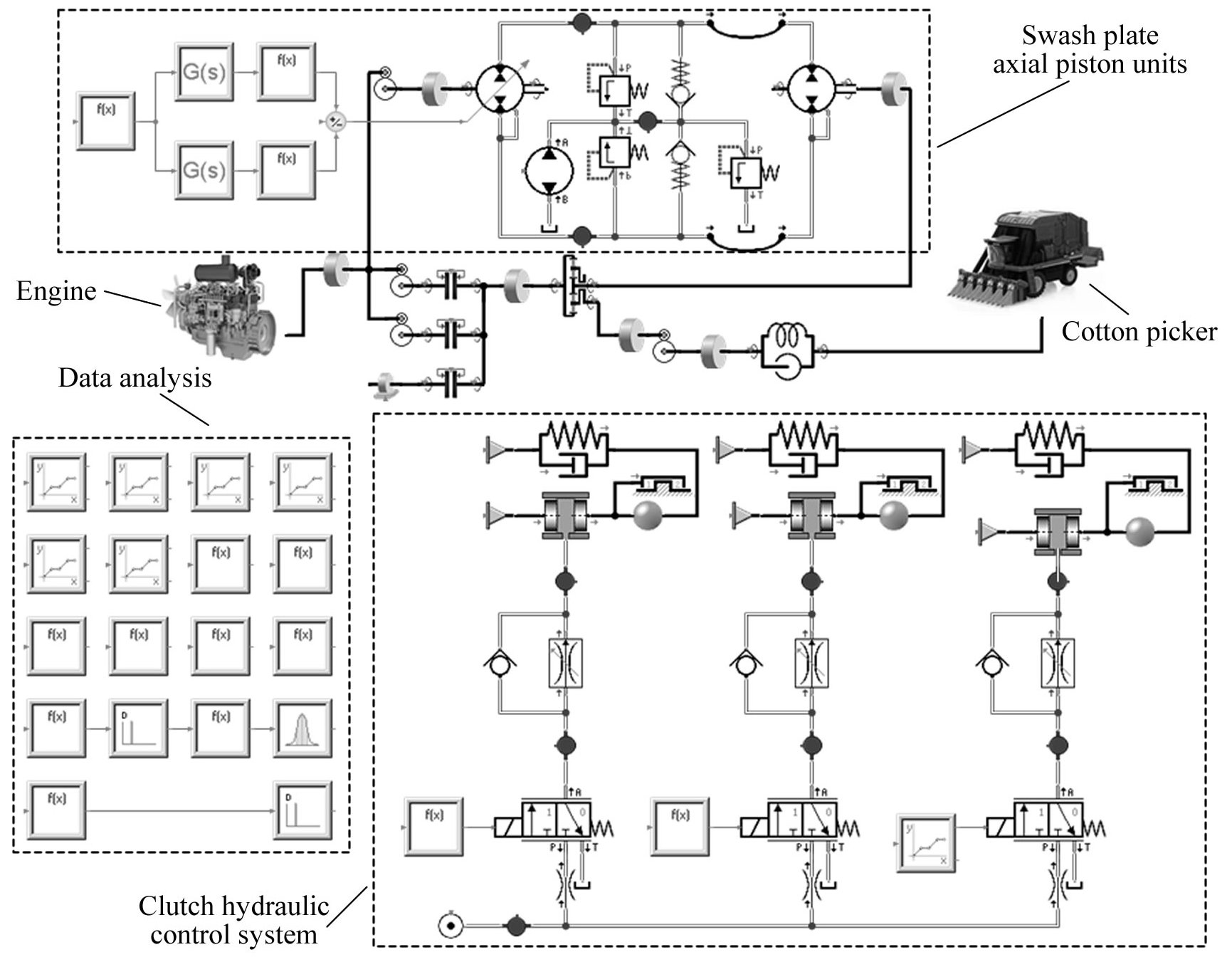
Based on Eqs. (7)–(22), the power-train model of the cotton picker is constructed under SimulationX, as shown in Fig. 2. It should be pointed out that the clutch hydraulic control system model is used to solve the oil pressure pc and the spring displacement x required in the calculation of Eq. (22) so as to obtain the normal force FN required for Eq. (20).
4.1 Swash plate axial piston units
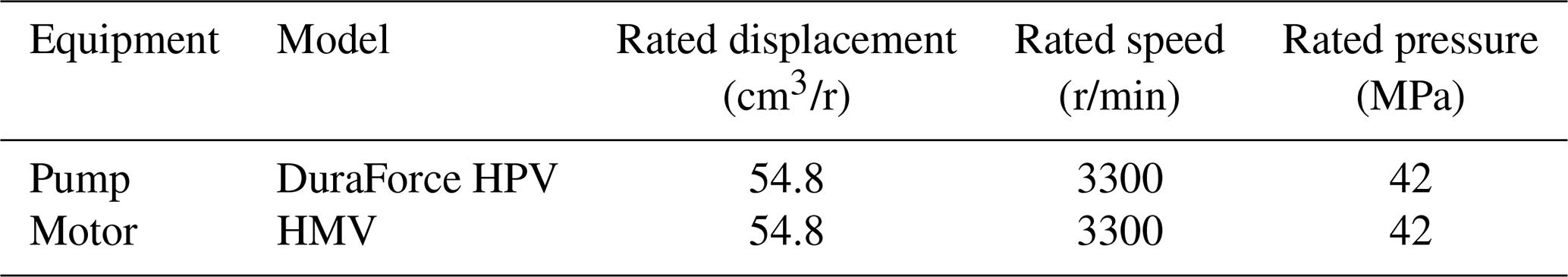
The swash plate axial piston units used in this study are composed of a variable displacement pump and a fixed displacement motor with the same rated displacement produced by Linde, and its parameters are shown in Table 4. The inlet and outlet of the pump are, respectively, connected with the outlet and inlet of the motor through the hydraulic hose lines, while the inlet and outlet of the charge pump are connected with the oil tank.
Table 4Parameters of variable displacement pump and fixed displacement motor.
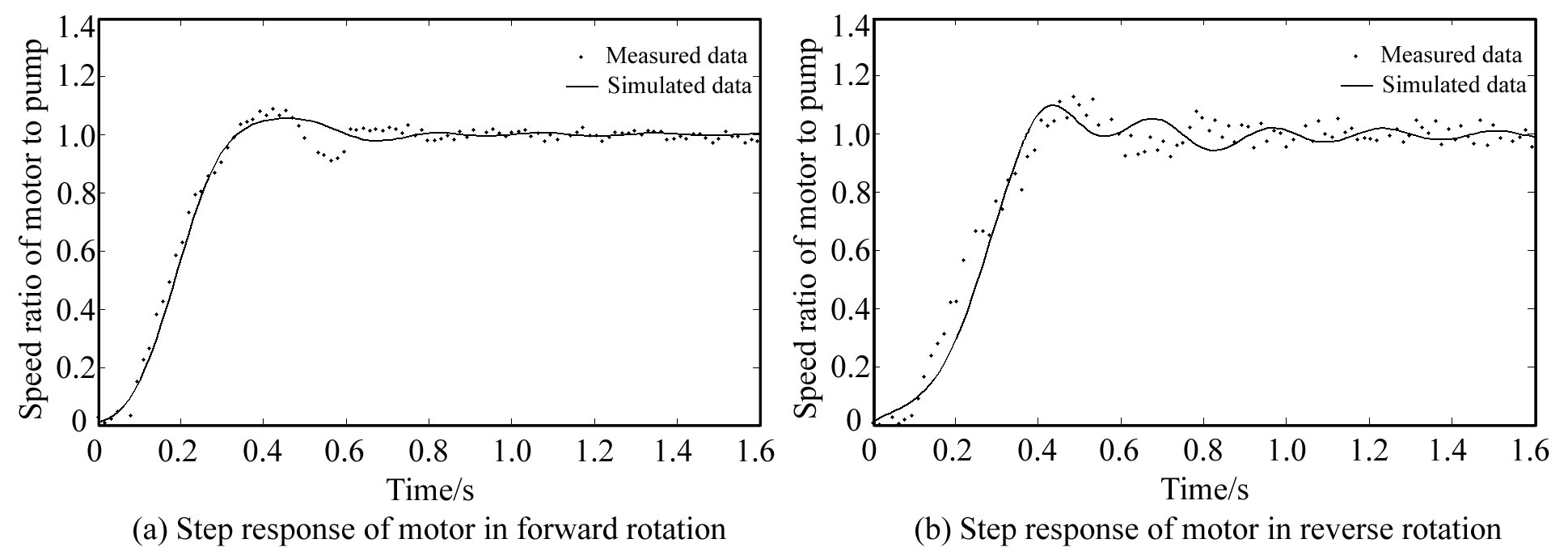
The step response of the swash plate axial piston units was measured in the author's early research (Wang et al., 2013). The test was carried out in different rotation directions of the motor, and the step amplitude of the displacement ratio is 0.42. The comparison between the test results and the simulation results of the step response is shown in Fig. 3. Obviously, the simulation model constructed in this paper can well simulate the dynamic characteristics of the swash plate axial piston units.
4.2 Clutch hydraulic control system
The WF012 wet clutch used in this study is a type of WF series clutch, which was produced by Shanghai Wind Co., Ltd., and its parameters are shown in Table 5. The test bench for testing the WF series clutch is shown in Fig. 4.


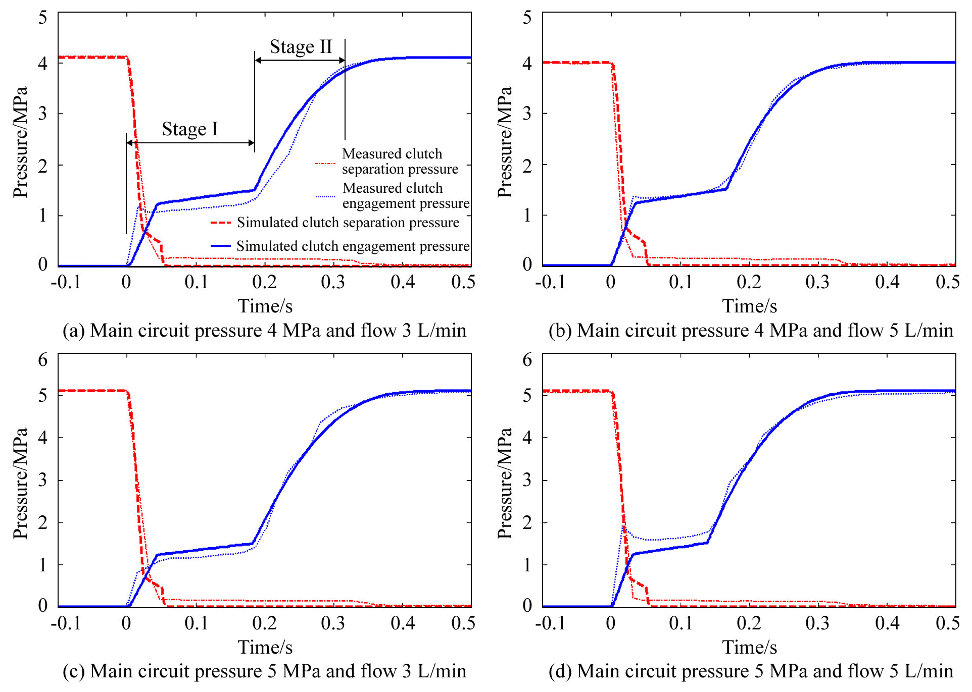
The pressure of the main circuit is set to 4 or 5 MPa through the relief valve, and the maximum charging flow of the clutch is set to 3 or 5 L/min through the speed control valve. During the test, power on or power off the solenoid valve, respectively, to obtain the step pressure response of the clutch when it is engaged or disengaged, as shown in Fig. 5. By comparing the simulation results with the test results, it can be seen that the model constructed in this paper can accurately simulate the variation of clutch pressure with time under the same test conditions.
According to the test results, the rising process of clutch pressure can be divided into two stages I and II: when the clutch works in stage I, the piston starts to move and the clutch pressure depends on the reaction force of return spring; when the clutch works in stage II, the piston moves to the end stop, and the clutch pressure rises rapidly until it reaches the pressure of the main circuit. Similarly, the separation of the clutch can also be divided into the pressure relief process of the clutch and the reset process of the piston, which will not be repeated here.
5.1 Influencing factors and evaluation indexes
There are many factors affecting the shift quality of the cotton picker, including controllable factors and working conditions. The former includes the pressure of the main circuit, the flow of speed regulating the valve and the action time of clutches C1 and C2; the latter includes the engine speed, the acceleration rate of the cotton picker and the weight of the cotton box. According to previous research (Ni et al., 2013), the engine speed has little effect on the shift quality of hydrostatic power split CVT. Therefore, it is not necessary to set the engine speed as the influencing factor, but set its value as the rated speed of 2200 r/min. In order to reveal the influence mechanism of the above factors on the shift quality of the cotton picker, it is necessary to carry out single factor analysis of the shift process. Considering that the minimum working pressure at which the WF012 clutch can be reliably engaged is 3 MPa and the allowable pressure of its friction disc material is no more than 5 MPa, the pressure value of the main circuit is set as 4 MPa under the standard condition. Considering that the clutch engagement is too slow when the flow of the speed control valve is lower than 3 L/min and the influence on the clutch pressure curve is no longer significant when the flow is higher than 7 L/min, the flow of the speed control valve is set to 5 L/min under the standard working condition. Considering that an overly long interval action time of the two clutches will cause power interruption and an overly long overlapping action time of the two clutches will damage the transmission, the relative action time of the two clutches is limited to ±0.5 s, and 0 s is taken as its standard value. In addition, the acceleration of the cotton picker is expressed by the change rate of pump displacement, its value range is 5.48–16.44 cm3/s, and the default value is 10.96 cm3/s; the weight range of the cotton box is determined by its rated weight (2.5 t), and the default value is 1.25 t.
It should be pointed out that the purpose of this study is to reveal the influence mechanism of controllable factors and working conditions on the shift quality of the cotton picker. Therefore, the “peak jerk”, which is widely used in the research of vehicle ride comfort, is used as the evaluation index of the shift quality of the cotton picker, and its expression is as follows:
where J is the peak jerk of the cotton picker during a shift, m/s3; a is the acceleration of the cotton picker during a shift, m/s2.
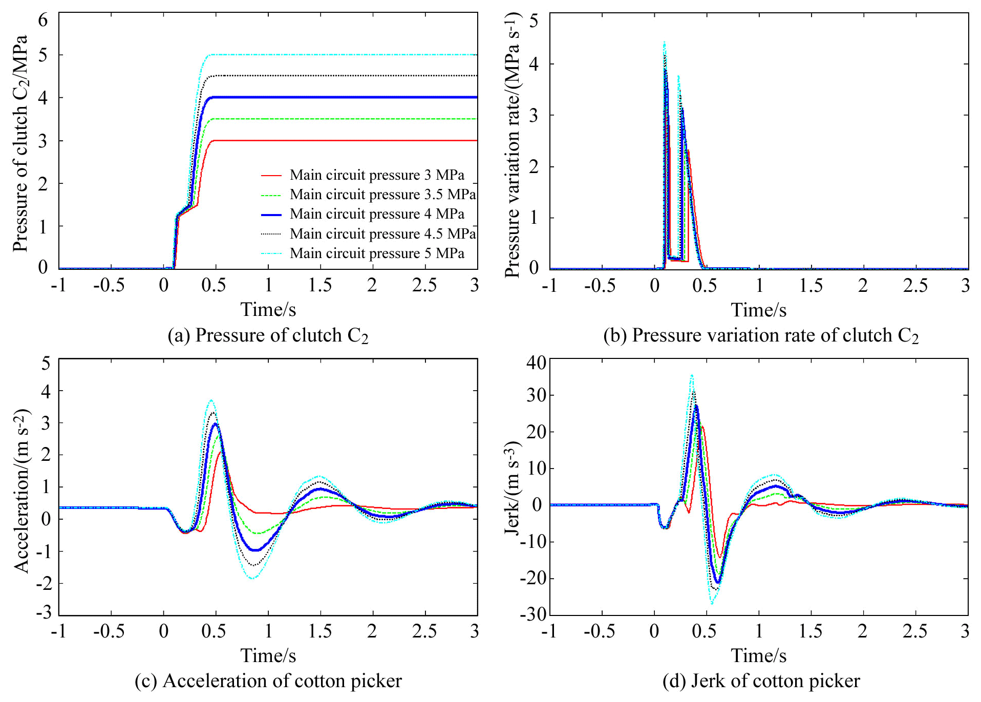
5.2 Effect of the main circuit pressure on shift quality
The influence of the main circuit pressure on the shift quality of the cotton picker is shown in Fig. 6. It can be seen from the figure that when the main circuit pressure changes between 3 and 5 MPa, its influence on the clutch pressure curve is reflected in two aspects: (1) with the increase in the main circuit pressure, the piston moves faster and the time of the pressure curve staying in stage I decreases. This also directly leads to the formation time of peak acceleration and peak jerk advancing with the increase in the main circuit pressure. (2) With the increase in the main circuit pressure, the slope of the pressure curve increases in stage II, which shortens the sliding time of the clutch friction disc. This also directly leads to the increase in peak acceleration and peak jerk with the increase in the main circuit pressure.
5.3 Effect of charging flow on shift quality
The influence of clutch-charging flow on the shift quality of the cotton picker is shown in Fig. 7. It can be seen from the figure that when the charging flow changes between 3 and 7 L/min, its influence on the clutch pressure curve is mainly reflected in the movement time of the piston. With the increase in the charging flow, the time of the pressure curve staying in stage I decreases. Although the charging flow affects the clutch engagement speed, it has little effect on the slope of the pressure curve in stage II, so that the peak acceleration and peak jerk do not change significantly with the charging flow. However, the influence of charging flow on piston moving speed is related to the flow range. If the charging flow is further reduced, the piston movement time will be increased and the power will be interrupted eventually.

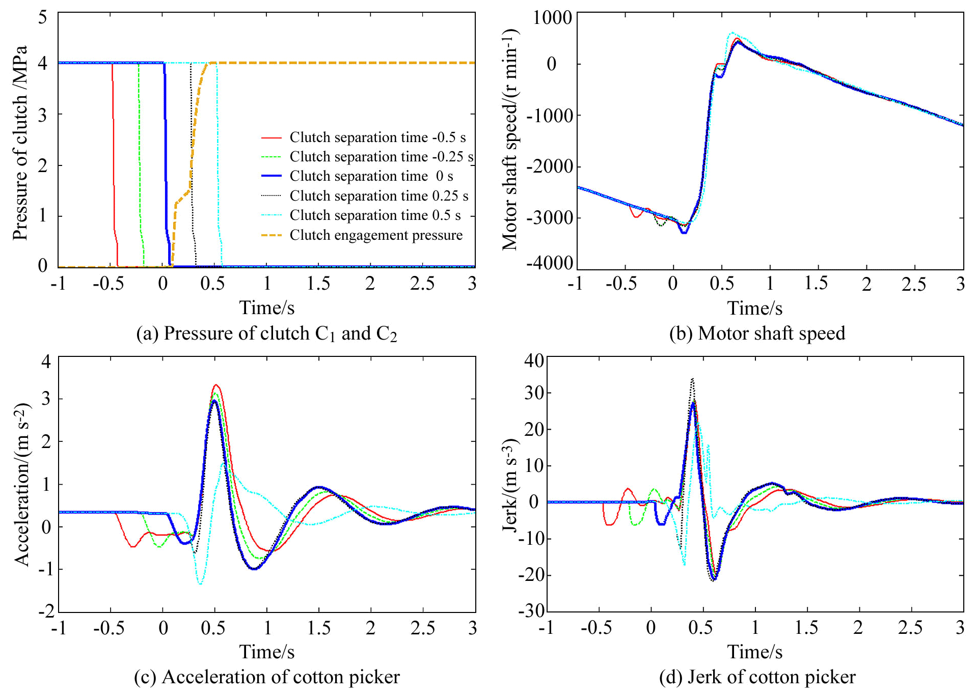
5.4 Effect of clutch separation time on shift quality
The influence of the separation time of clutch C1 on the shift quality of the cotton picker is shown in Fig. 8. It can be seen from the figure that when the separation time of clutch C1 changes between −0.5 and 0.5 s, the time for the first fluctuation of acceleration and jerk also changes. This shows that the first fluctuation of acceleration and jerk is caused by the separation of clutch C1, while the formation of peak acceleration and peak jerk is caused by the engagement of clutch C2. Moreover, the fluctuation of motor speed in the forward direction is also related to the separation of clutch C1. Generally speaking, the influence of the separation time of clutch C1 on the shift quality of the cotton picker can be divided into three situations: (1) when the separation time of clutch C1 is less than 0.25 s, power interruption can be caused. In theory, the later clutch C1 releases pressure, the shorter the power interruption time and the less the speed of the cotton picker decreases, which makes clutch C2 produce a smaller peak value of acceleration and jerk when engaged. In fact, due to the narrow value range of the separation time of clutch C1 in this study, the jerk change in the cotton picker caused by power interruption is not very significant. (2) When the separation time of clutch C1 is equal to 0.25 s, the motor will reverse before the clutch pressure is released. In this case, the speed of the cotton picker will decrease rapidly with the reverse of the motor, which makes the cotton picker produce higher peak value of acceleration and jerk in the pressure-rising stage of clutch C2. (3) When the separation time of clutch C1 is greater than 0.25 s, it will temporarily engage with clutch C2 at the same time. In this case, although the speed of the cotton picker is greatly reduced due to motor reversal before the pressure relief of clutch C1, the sliding process of clutch C2 is affected by the braking of clutch C1, thus avoiding the shift impact caused by the fast engagement of clutch C2. Moreover, the fluctuation of the motor speed before reversing also tends to disappear, indicating that the motor does not lose load. Based on the above reasons, with the change in separation time of clutch C1 from −0.5 to 0.5 s, the peak value of acceleration and jerk of the cotton picker first decreased slightly, then increased, and finally decreased rapidly.
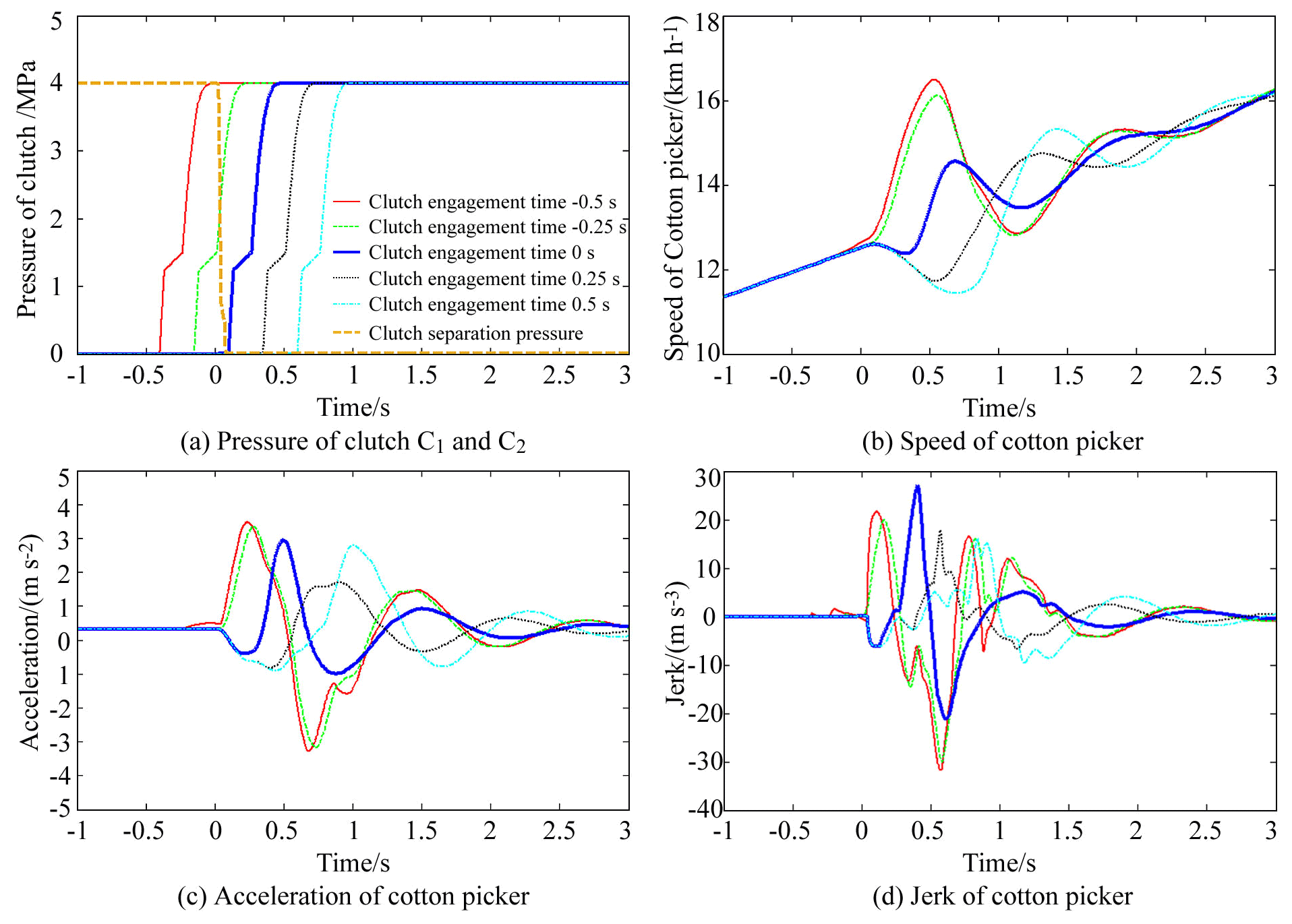
5.5 Effect of clutch engagement time on shift quality
The influence of the engagement time of clutch C2 on the shift quality of the cotton picker is shown in Fig. 9. It can be seen from the figure that when the engagement time of clutch C2 changes between −0.5 and 0.5 s, its influence on the shift quality of the cotton picker can also be divided into two situations: (1) when the engagement time of clutch C2 is less than or equal to −0.25 s, the motor has not decelerated in the reverse direction when the clutch begins to engage. Because the speed of the cotton picker when clutch C2 is engaged is much higher than that when clutch C1 is engaged at the same motor speed, the speed of the cotton picker suddenly increases at the beginning of the shift. It can be seen from the figure that regardless of whether the engagement time of clutch C2 is −0.5 or −0.25 s, the acceleration process of the cotton picker during the shift begins with the separation time of clutch C1. This phenomenon shows that clutch C1 is in a stable engagement state before pressure relief, which has a strong braking effect on the engagement of clutch C2, thus forcing clutch C2 to be in a sliding state. For this reason, when the engagement time of clutch C2 is −0.5 s, the pressure of clutch C2 has been increased before the pressure relief of clutch C1, so that clutch C2 ends the sliding state at a very fast speed with the pressure relief of clutch C1, resulting in a higher shift impact than when it is engaged at −0.25 s. (2) When the engagement time of clutch C2 is greater than or equal to 0 s, clutch C2 is engaged after the pressure relief of clutch C1, and the power of the cotton picker is interrupted. Moreover, the speed of the cotton picker when clutch C2 is engaged is much higher than that when clutch C1 is engaged at the same motor speed. Therefore, the earlier clutch C2 is engaged, the higher the instantaneous speed of the motor and the greater the shift impact of the cotton picker. Especially when clutch C2 is engaged at 0 s, the shift quality of the cotton picker becomes lowest. By contrast, when clutch C2 is engaged in 0.25 or 0.5 s, respectively, the motor is about to complete the speed adjustment. Affected by the dynamic characteristics of the motor itself, the two jerk curves are not only complex in shape, but also have no significant difference. For the above reasons, with the change in engagement time of clutch C2 from −0.5 to 0.5 s, the peak value of the jerk of the cotton picker first decreases slightly, then increases, and finally decreases slowly. It should be noted that even if clutch C2 is engaged at 0.5 s, the motor does not completely end the speed adjustment. Therefore, if the engagement time of clutch C2 is further delayed, the shift quality of the cotton picker will change greatly, but it seems unnecessary to create such a long power interruption time in the research.
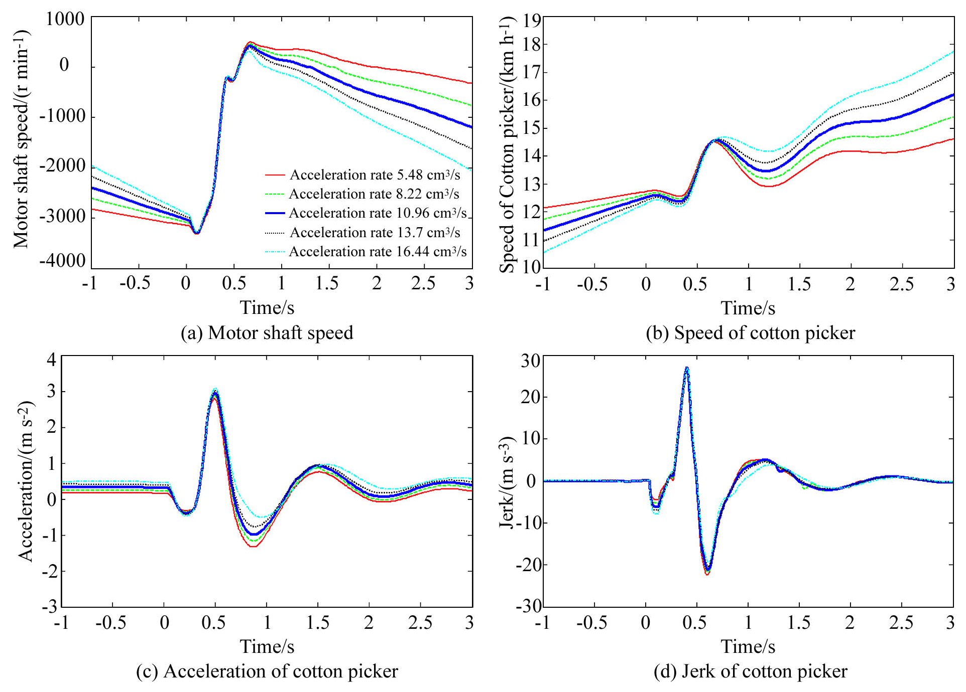
5.6 Effect of acceleration rate of the cotton picker on shift quality
The influence of acceleration rate on the shift quality of the cotton picker is shown in Fig. 10. It can be seen from the figure that when the acceleration rate changes between 5.48 and 16.44 cm3/s, the speed response of the motor is restricted by its own dynamic characteristics and lags behind the change in the pump displacement. Therefore, the motor fails to reach the theoretical speed before the first deceleration, and the higher the acceleration rate, the lower the actual speed of the cotton picker at the beginning of the shift. At the same time, because the motor speed will enter a short adjustment period after returning to zero, the cotton picker will reach almost the same speed at different acceleration rates. Therefore, the increase in acceleration rate increases the speed difference of the cotton picker from the motor reversing to its speed returning to zero and then improves the peak value of acceleration. However, with the increase in acceleration rate, the cotton picker has a high theoretical speed at the end of the shift, which reduces the difference between the overshoot speed after clutch C2 engagement and the theoretical speed after shifting and then makes the acceleration curve have a lower slope and a smaller peak jerk after clutch C2 engagement. For the above reasons, with the acceleration rate changing from 5.48 to 16.44 cm3/s, the peak acceleration of the cotton picker generally shows an upward trend, while the change rule of the jerk curve is the opposite. It should be noted that although the above rule is monotonous, the numerical difference is not significant in the range of the acceleration rate 5.48–16.44 cm3/s.
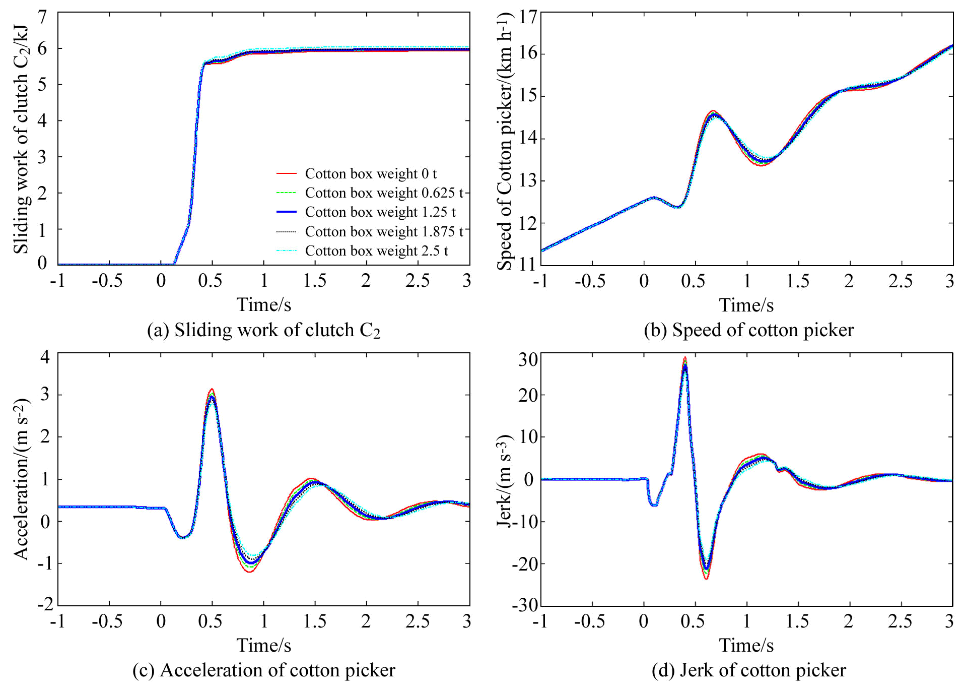
5.7 Effect of cotton box weight on shift quality
The influence of cotton box weight on the shift quality of the cotton picker is shown in Fig. 11. It can be seen from the figure that when the weight of the cotton box changes between 0 and 2.5 t, the heavier the cotton box is, the more strongly the inertia of the cotton picker suppresses the speed fluctuation, and the smaller the peak value of the acceleration and jerk of the cotton picker are. However, correspondingly, with the increase in the cotton box weight, the sliding work of clutch C2 also increases, which indicates that the clutch absorbs and dissipates more energy when the weight of the cotton box increases.
Table 6Simulation scheme based on the L9(34) orthogonal table.

5.8 Optimization of shift quality
Considering that the working conditions of the cotton picker are uncertain and uncontrollable, the key to the optimization of shift quality is to determine the best combination of parameters under each working condition. Let the acceleration rate be 5.48, 8.22, 10.96, 13.7 and 16.44 cm3/s, respectively, and the weight of the cotton box be 0, 0.625, 1.25, 1.875 and 2.5 t, respectively; then the number of working conditions can be enumerated as . For each group of working conditions, the main circuit pressure, charging flow, clutch separation time and clutch engagement time are combined based on the L9(34) orthogonal table to obtain the simulation scheme as shown in Table 6. Because the range analysis method to find the optimal solution will bring the solution jump under similar conditions, this study directly selects the optimal combination of parameters from the results of the orthogonal simulation scheme. After times of simulation, it is found that no matter how the working conditions change, the optimal combination of parameters is always main circuit pressure 4 MPa, charging flow 5 L/min, clutch separation time 0.5 s and clutch engagement time −0.5 s. Under this parameter combination, the peak jerk of the cotton picker under different working conditions is generally limited between 8 and 12 m/s3, as shown in Fig. 12.

In this study, the transmission system of a cotton picker equipped with hydrostatic power split CVT was analysed, and its mathematical model was established. The influence law and mechanism of various factors in the shift quality of the cotton picker were discussed, and the following conclusions were drawn.
-
Overly high pressure of the main circuit can aggravate the shift impact level and reduce the shift quality of the cotton picker.
-
The effect of clutch action time on the shift quality of the cotton picker is not monotonous. Whether it is clutch C1 or C2, with the delay of clutch action time, the shift impact of the cotton picker first decreased slightly, then increased, and finally decreased.
-
In the range given in this study, the influence of clutch-charging flow and acceleration rate on the shift quality of the cotton picker is not significant.
-
With the increase in the cotton box weight, the shift quality of the cotton picker is slightly improved, but this is at the cost of increasing the sliding work of the clutch and consuming more sliding friction energy, which will shorten the service life of the clutch.
-
If different factors are evaluated together, the optimal combination of parameters under different working conditions is main circuit pressure 4 MPa, charging flow 5 L/min, clutch separation time 0.5 s and clutch engagement time −0.5 s.
-
Through parameter optimization, the peak jerk of the cotton picker under different working conditions can be limited within 8–12 m/s3, which shows that the hydrostatic power split CVT proposed in this study has high feasibility in the application of the cotton picker.
All the data used in this paper can be obtained by request from the corresponding author.
GW proposed the concept of this paper. WC, ZX and YZ worked together to complete the simulation work. GW and YW wrote the paper. ZX and MX edited and verified all the formulas and pictures used in this paper.
The authors declare that they have no conflict of interest.
The authors thank the reviewers for their valuable comments and Copernicus Publications for their language and typesetting services.
This research has been supported by the Shandong Provincial Natural Science Foundation (grant no. ZR2020QE163), the Key Technology Research and Development Program of Shandong (grant no. 2018GNC112008) and the Shandong Provincial Agricultural Machinery Research and Development Program (grant no. 2017YF026).
This paper was edited by Dario Richiedei and reviewed by two anonymous referees.
Dam, P., Bilgram, M., Brandi, A., Frederiksen, M., Langer, T. H., and Samani, A.: Evaluation of the effect of a newly developed steering unit with enhanced self-alignment and deadband on mental workload during driving of agricultural tractors, Appl. Ergon., 89, 103217, https://doi.org/10.1016/j.apergo.2020.103217, 2020.
Delhom, C. D., Indest, M. O., Wanjura, J. D., Armijo, C. B., and Pelletier, C. D.: Effects of harvesting and ginning practices on Southern High Plains cotton: textile quality, Text. Res. J., 90, 537–546, https://doi.org/10.1177/0040517519871942, 2019.
İnce, E. and Güler, M. A.: On the advantages of the new power-split infinitely variable transmission over conventional mechanical transmissions based on fuel consumption analysis, J. Clean Prod., 244, 118795, https://doi.org/10.1016/j.jclepro.2019.118795, 2020.
Iqbal, S., Al-bender, F., Ompusunggu, A. P., Pluymers, B., and Desmet, W.: Modeling and analysis of wet friction clutch engagement dynamics, Mech. Syst. Signal Pr., 60–61, 420–436, https://doi.org/10.1016/j.ymssp.2014.12.024, 2015.
ITI GmbH: ITI SimulationX Help, ITI GmbH Headquarters, Dresden, 2012.
Karagoz, R. and Batselier, K.: Nonlinear system identification with regularized Tensor Network B-splines, Automatica, 122, 109300, https://doi.org/10.1016/j.automatica.2020.109300, 2020.
Kazama, E. H., Silva, R. P. D., Ormond, A. T. S., Alcântara A. S., and Vale, W. G. D.: Cotton and fiber quality in function of picker harvest speed, Rev. Bras. Eng. Agr. Amb., 22, 583–588, https://doi.org/10.1590/1807-1929/agriambi.v22n8p583-588, 2018.
Li, B., Sun, D., Hu, M., Zhou, X., Wang, D., Xia, Y., and You, Y.: Automatic gear-shifting strategy for fuel saving by tractors based on real-time identification of draught force characteristics, Biosyst. Eng., 193, 46–61, https://doi.org/10.1016/j.biosystemseng.2020.02.008, 2020.
Maier, C. C., Schröders, S., Ebner, W., Köster, M., Fidlin, A., and Hametner, C.: Modeling and nonlinear parameter identification for hydraulic servo-systems with switching properties, Mechatronics, 61, 83–95, https://doi.org/10.1016/j.mechatronics.2019.05.005, 2019.
Ni, X., Zhu, S., Zhang, H., Chang, Y., Ouyang, D., and Wang, G.: Experiment of shift quality factors for hydro-mechanical CVT, Transactions of the Chinese Society for Agricultural Machinery, 44, 29–34, https://doi.org/10.6041/j.issn.1000-1298.2013.06.006, 2013 (in Chinese).
Renius, K. T.: Fundamentals of Tractor Design, Springer Nature Switzerland AG, Cham, 2020.
Renius, K. T. and Resch, R.: Continuously variable tractor transmissions, Agriculture Equipment Technology Conference, 14–16 February 2005, Louisville, 2005.
Rotella, D. and Cammalleri, M.: Power losses in power-split CVTs: a fast black-box approximate method, Mech. Mach. Theory, 128, 528–543, https://doi.org/10.1016/j.mechmachtheory.2018.06.011, 2018.
Wang, G., Song, Y., Wang, J., Xiao, M., Cao, Y., Chen, W., and Wang, J.: Shift quality of tractors fitted with hydrostatic power split CVT during starting, Biosyst. Eng., 196, 183–201, https://doi.org/10.1016/j.biosystemseng.2020.06.001, 2020.
Wang, G., Zhu, S., Wang, S., Shi, L., Ni, X., and Ouyang, D.: Speed ratio control of tractor hydraulic mechanical CVT, Transactions of the Chinese Society of Agricultural Engineering (Transactions of the CSAE), 29, 17–23, available at: http://www.tcsae.org/nygcxb/ch/reader/view_abstract.aspx?file_no=20130702 (last access: 29 May 2021), 2013 (In Chinese).
Yu, L., Ma, B., Chen, M., Xue, J., and Zhao, P.: Variation mechanism of the friction torque in a Cu-based wet clutch affected by operating parameters, Tribology International., 147, 106169, https://doi.org/10.1016/j.triboint.2020.106169, 2020.
Yuan, S., Wei, C., and Zhang, Y.: Influencing factors for dynamic characteristics of hydro-mechanical continuously variable transmission, Transactions of the Chinese Society of Agricultural Engineering, 24, 33–38, https://doi.org/10.3321/j.issn:1002-6819.2008.02.007, 2008 (in Chinese).
Zeman, P., Kemmetmüller, W., and Kugi, A.: Energy-efficient constrained control of a hydrostatic power split drive, IFAC-PapersOnLine, 50, 4775–4780, https://doi.org/10.1016/j.ifacol.2017.08.959, 2017.
Zhu, Z., Gao, X., Cao, L., Cai, Y., and Pan, D.: Research on the shift strategy of HMCVT based on the physical parameters and shift time, Appl. Math. Model., 40, 6889–6907, https://doi.org/10.1016/j.apm.2016.02.017, 2016.