the Creative Commons Attribution 4.0 License.
the Creative Commons Attribution 4.0 License.
 | 04 Feb 2021
Prediction of angle error due to torsional deformation in non-circular grinding
Joon Jang
Woo Chun Choi
Non-circular grinding is used in the grinding of crankshafts. In contrast to general grinding, the precision in non-circular grinding is affected by torsional deformation, which results in errors in the grinding depth. In this study, an equation to detect the angle error caused by torsional deformation is established considering the grinding force, the structure of the crankshaft, and the distribution of torque. The angle error due to torsional deformation was found to be up to 0.44 arcsec, which is 5 % of the angle error obtained from previous studies. This difference occurred as the previous studies did not exclusively detect the errors caused by bending deformation and torsional deformation. However, the established equation detects these errors separately. The fundamental cause of the two errors is the change in the structure of the crankshaft caused by bending. Further, the errors were eliminated via steady rest to reduce the bending of the crankshaft. Although the proposed equation is not entirely error-free, the results obtained by the equation have higher accuracy than those of previous studies.
- Article
(3029 KB) - Full-text XML
- BibTeX
- EndNote


A crankshaft is a major component of an engine and affects its working conditions. Further, the grinding precision of a crankshaft affects the life of the workpiece. Continuous research on the improvement of the grinding precision of crankshafts has been conducted previously (Oliveira et al., 2009).
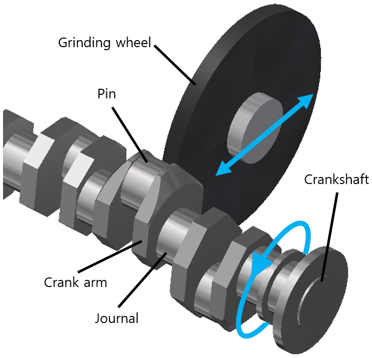
A crankshaft consists of journals and pins. The centerlines of the journal and pin are different from the axes of the pins. Consequently, non-circular methods are used as the traditional method of cylinder grinding, which is time-consuming. In the non-circular method, the crankshaft rotates about the journal axis while the grinding wheel moves back and forth following the trajectory of the pin, which can be seen graphically in Fig. 1 (Tönshoff et al., 1998).
Numerous studies are being conducted on the improvement of the precision of crankshafts. In non-circular grinding, grinding and measurement are performed concurrently, and the measured error is compensated by re-grinding. Studies have been conducted to investigate methods to improve the quality of measurement and increase the grinding speed. The contour error was predicted using the position of the grinding wheel and workpiece without using additional measurement equipment (Huan and Ma, 2010). A measurement method was suggested for high grinding speed using a V-block (Yu et al., 2015). The quality of measurement was improved, and the grinding time was reduced by using an optical sensor (Keferstein et al., 2008). Additionally, a study was conducted to reduce errors by adjusting the height of steady rests using data from real-time measurements (Shen et al., 2015). These studies can effectively reduce errors to a certain level.
However, for higher precision, the cause of error needs to be found. Consequently, studies on analyzing the cause of error have also been conducted. Analyses on the grinding force and its role in performance error have also been performed (Malkin and Guo, 2008; Durgumahanti et al., 2010; Walsh et al., 2004; Badger and Torrance, 2000; Shen et al., 2006; Jang and Choi, 2018). Consequently, it was found that the bend and twist in the crankshaft led to precision errors. Further, in cylindrical grinding and non-circular grinding, torsional deformation occurs because of the grinding force. Errors in the cylindrical grinding were not due to torsional deformation. However, in non-circular grinding, the cutting depth error was caused by torsional deformation. Therefore, torsional deformation plays a significant role in non-circular grinding. Numerous studies have considered bending deformation because its error is larger than that of torsional deformation. However, studies on torsional deformation have also been performed. Generally, studies on the prediction and compensation of the angle error due to torsional deformation have been conducted (Yu et al., 2012; Zhang and Yao, 2015; Li et al., 2015). However, these studies did not individually analyze the torsional and bending deformation. Since these studies measure the grinding trajectory, they include both torsional and bending deformations.
This study aims to predict the angle error resulting from torsional deformation in non-circular grinding using the equation established herein. Unlike previous studies, the effect of bending deformation on the crankshaft is omitted from the equation.
During grinding via a crankshaft pin, a grinding force is applied at the contact point between the grinding wheel and the pin. The grinding force is expressed as a tangential force (Ft) and normal force (Fn) at the grinding contact point. Fn and Ft can be rewritten as the vertical force (Fu) and horizontal force (Fv). “Vertical” indicates vertical to the direction of the crankshaft arm, and “horizontal” indicates horizontal to the direction of the crankshaft arm. Among these forces, only Fv results in torsional deformation, which leads to the angle error. This relationship is illustrated in Fig. 2.
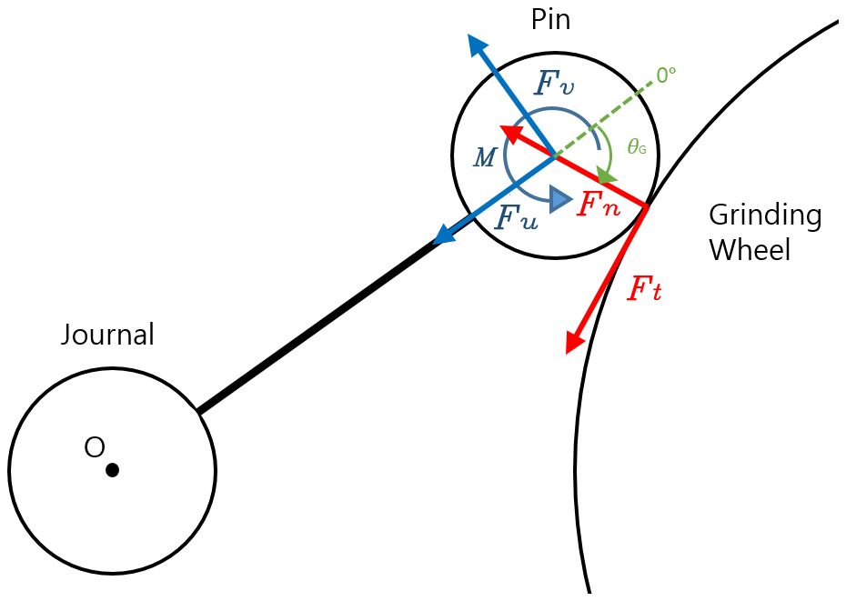
The relationship between forces is expressed as follows:
where Fu is the vertical force, Fn is the normal force, Ft is the tangential force, Fv is the horizontal force, and θG is the grinding position. The rotation angle error is the error under investigation in this study. However, for convenience, F is expressed as the grinding position as opposed to the rotation angle. The relationship between the rotation angle and the grinding position is as follows:
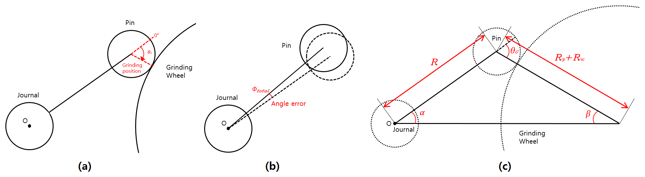
where α is the rotation angle, θG is the grinding position, Rw is the radius of the grinding wheel, Rp is the radius of the pin, and R is the distance between the center of the journal and pin. This can be illustrated graphically in Fig. 3.
In this study, torsional deformation refers to torsional deformation of the crankshaft due to the torque generated by Fv. The crankshaft should be divided into the journal, pin, and crank arm sections to simplify the calculation. The journal and the pin have a cylindrical shape, while the arm has a beam shape. The angle error due to the torsional deformation referred to in this study is caused by Fv. It is the sum of the angle error caused by the torsional deformation of the pin and journal and the bending deformation of the arm. Therefore, the angle error can be represented as follows:
where ϕtotal is the total angle error, ϕtorisional is the angle error due to torsional deformation, and ϕbending is the angle error due to bending deformation.
First, ϕtorisional can be expressed as the length of the journal and pin. During the grinding process, the torque of the crankshaft is distributed to the headstock and tailstock, which holds the ends of the crankshaft against the grinding force. Torsional error due to the torque of the headstock (TH) is expressed as follows:
where TH is the torque generated from the headstock, LHi is the length from the end of the crankshaft near the headstock to the ith pin, i is the order of the ground pin, b is the width of the arm, Ipi is the moment of inertia of the journal and pin, and Lp is the length of the pin. The first term of Eq. (4) is based on the distance from the end of the crankshaft close to the headstock to the ground pin. It is the angle error generated through torsional deformation due to TH in the cylinder, which has a length that excludes the width of the arm from the end of the crankshaft to the ground pin. The bending deformation is excluded from the torsional deformation because it is used to calculate the angle error of the arm. If the center of the pin is ground, it is necessary to add the resulting angle error at half the pin, which represents the second term of the equation.
Second, ϕbending can be expressed as the angle error because of bending deformation of the arms obtained from the relationship between force and angle, assuming that the arm is a beam. The angle error formed by the bending deformation from the headstock to the ground pin is expressed as
where R and Ia are the length and moment of inertia of the arm, respectively. The bending deformation of the arm is generated by Fv. The total angle error is the angle error of each arm multiplied by the number of arms from the end of the crankshaft near the headstock to the ground pin. It represents the total angle error due to the bending deformation from the end of the crankshaft near the headstock to the ground pin.
The angle error at the grinding point is given by the sum of the angle errors due to torsion and bending. It is expressed as follows:
This is the angle error summed from the headstock to the grinding point. As the value of TH is unknown, the angle error cannot be obtained. To obtain the TH value, the principle, the sum of the angle error from the headstock, is equal to the sum of the angle error from the tailstock, and the sum of TH and TT, which is equal to TG (torque by grinding force), is applied. The angle error added from the tailstock is expressed as follows:
where TT is the torque generated from the tailstock, LTj is the length from the end of the crankshaft near the headstock to the pin being ground, and N is the number of pins in the crankshaft.
As TG generated by the grinding force is divided into TH and TT, it can be expressed as
TH and TT can be obtained using the equations ϕtotal_H=ϕtotal_T and . The angle error ϕtotal can be obtained by substituting the torque value obtained. The resulting equation is applied to the crankshaft, and the angle error based on the grinding position of the first pin to the seventh pin is calculated using MATLAB.
The angle error obtained from the equation is difficult to measure during experiments because it is it given by the difference in the position of the journal and pin. Therefore, in this study, the equation is verified through FEM analysis.
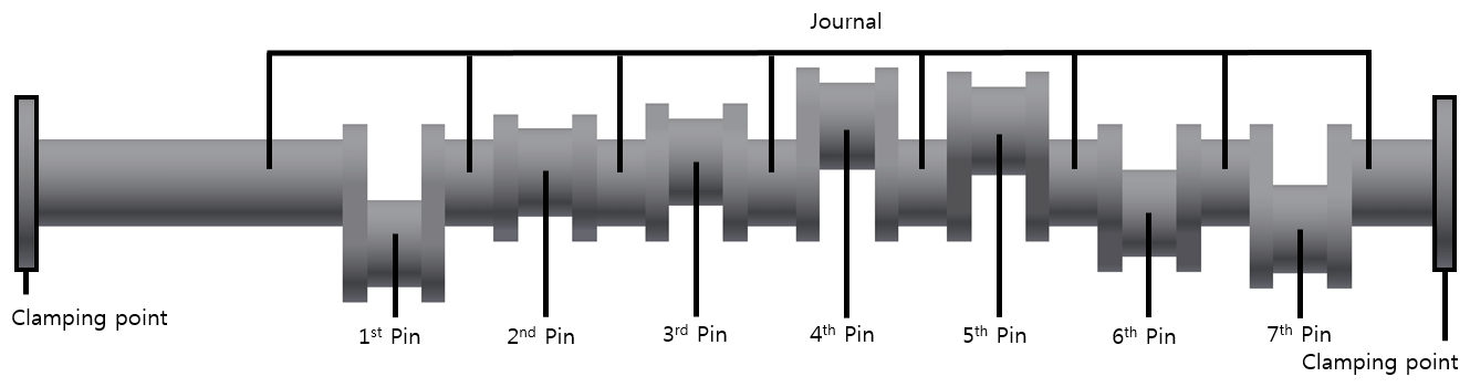
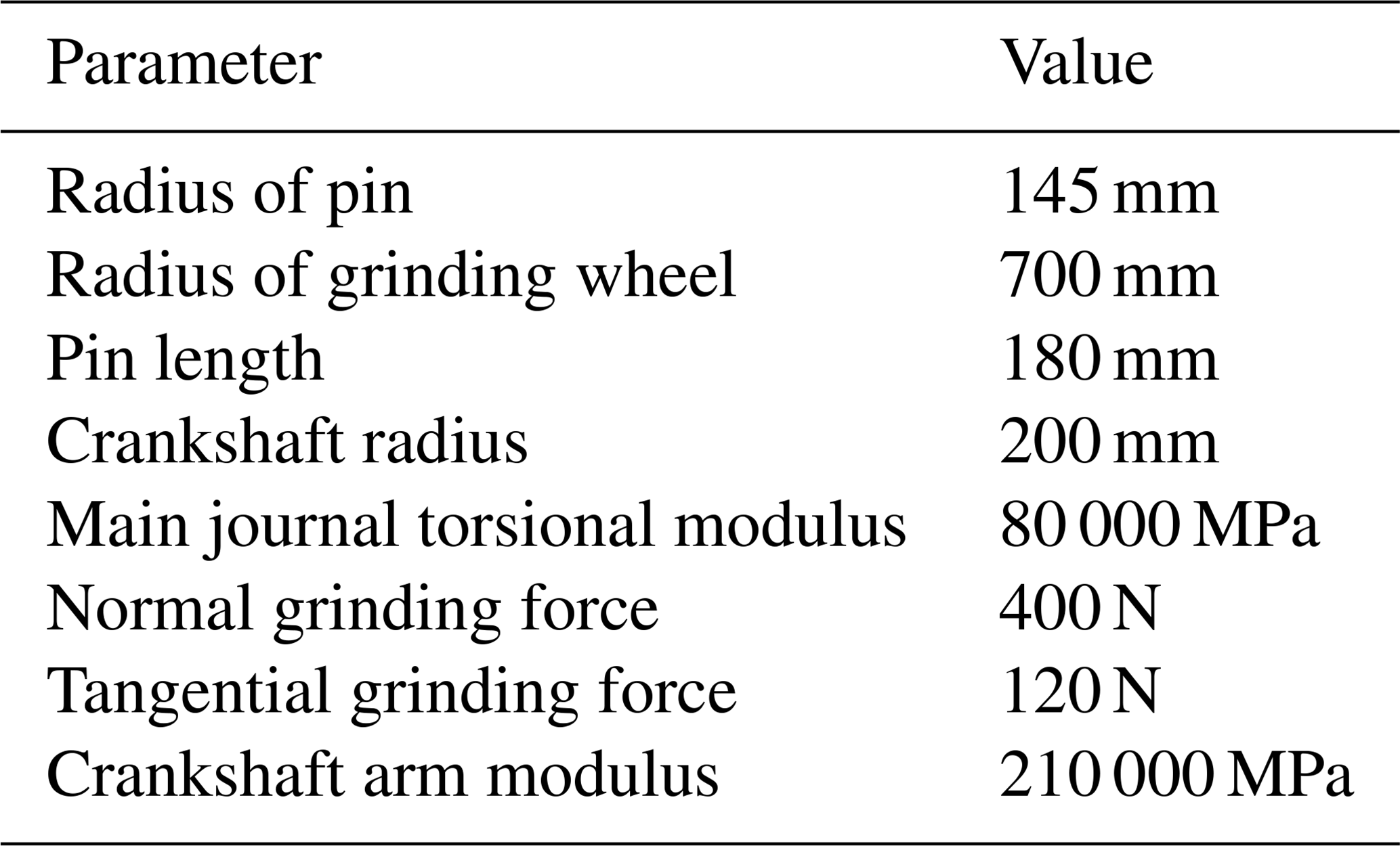
Figure 4 shows the crankshaft used in this study, and the material properties are listed in Table 1. The crankshaft consists of seven pins that have the same radii as the journals. The model is designed such that both ends of the crankshaft are held to the stock, there is no steady rest, and the grinding force is applied to the grinding point while the pin is being ground. The grinding position was adjusted at 10∘ intervals, and the results were recorded.
4.1 Validation of FEM with the previous study
When calculating torsional deformation, if the deformation of the pin (Pu, Pv) is used as is, then the bending of the journal (Ju, Jv) due to the grinding force is included. As shown in Fig. 5, the correct value is ϕ, but ϕub (that angle error including the bending of the journal) is calculated. Therefore, ϕ should be calculated as the difference between the deformations of the pin and journal.

In the study of Li et al. (2015), the angle error due to torsional deformation was obtained by tracing the grinding point. The method of tracing the grinding point only considers the position of the pin and hence cannot be regarded as torsional deformation because it involves the bending deformation of the journal.
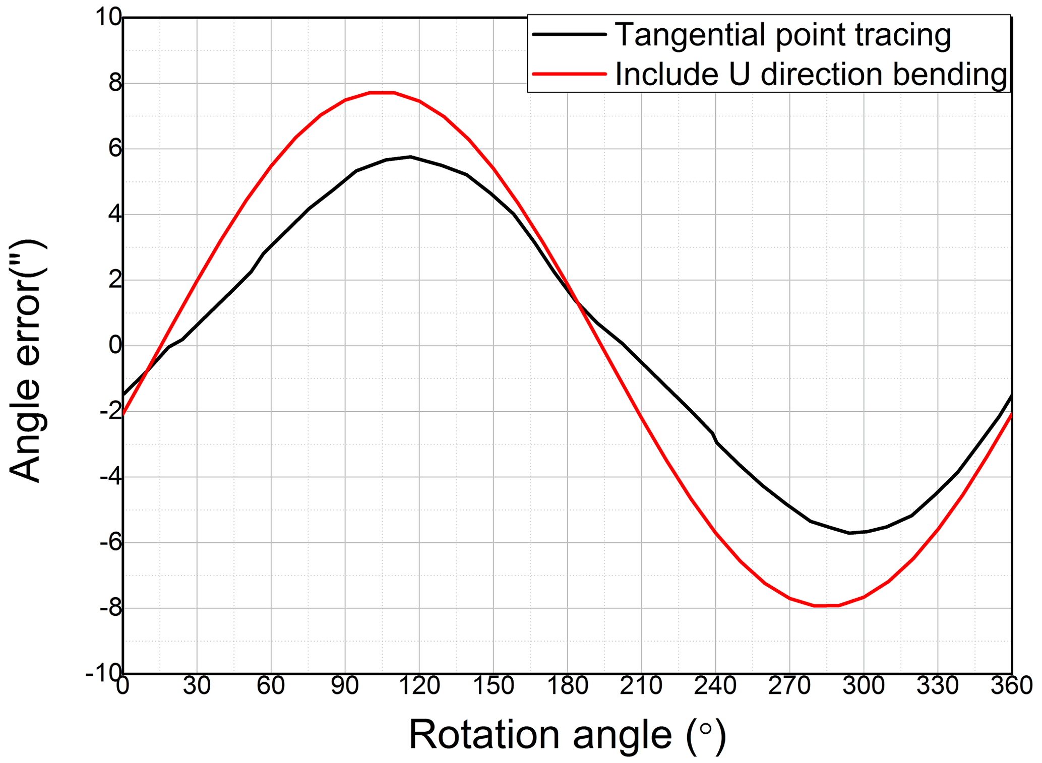
As this study utilizes the crankshaft and grinding force as in the study of Li et al. (2015), the FEM model presented by Li et al. (2015) can be used for the analysis in this study. In this study, the FEM model is used to obtain angle errors at pins, including the bending effect, as shown in Fig. 6. The fourth pin angle errors for both studies are compared and presented in Fig. 7. The results of the FEM model, including the bending effect, are similar to those of Li et al. (2015). The results are confirmed by tracing the grinding point including the bending deformation of the journal. This validates the FEM model used in this study.
In this study, the torsional deformation of the first pin to the seventh pin was obtained through pin and journal deformations (Pu, Pv, Ju, Jv) while the pin was being ground.
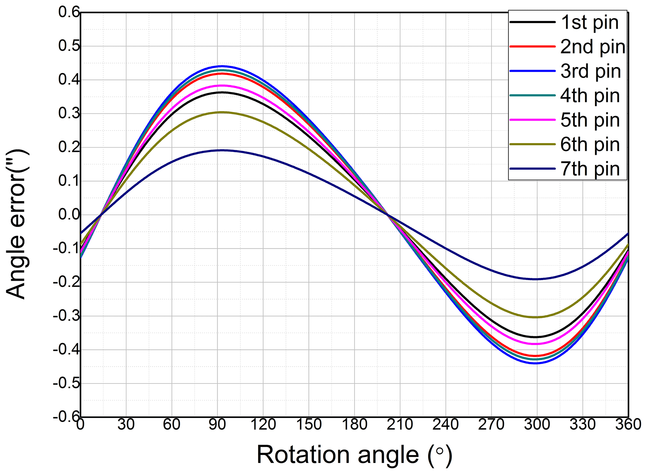
From the angle error equation, the angle errors based on the rotation angle of the first pin to the seventh pin were calculated using MATLAB, as shown in Fig. 8. The results are observed to have a periodic form, and there is no difference in the angle errors when the rotation angles are approximately 15 and 200∘. The difference in the angle error is maximum at rotation angles of 90 and 300∘. As the torque distribution varies depending on the pin, the maximum angle error is dependent on the pin, and the value ranges between 0.19 and 0.44 arcsec. The pin with the largest angle error is the third, fourth, second, fifth, first, sixth, and seventh pins.
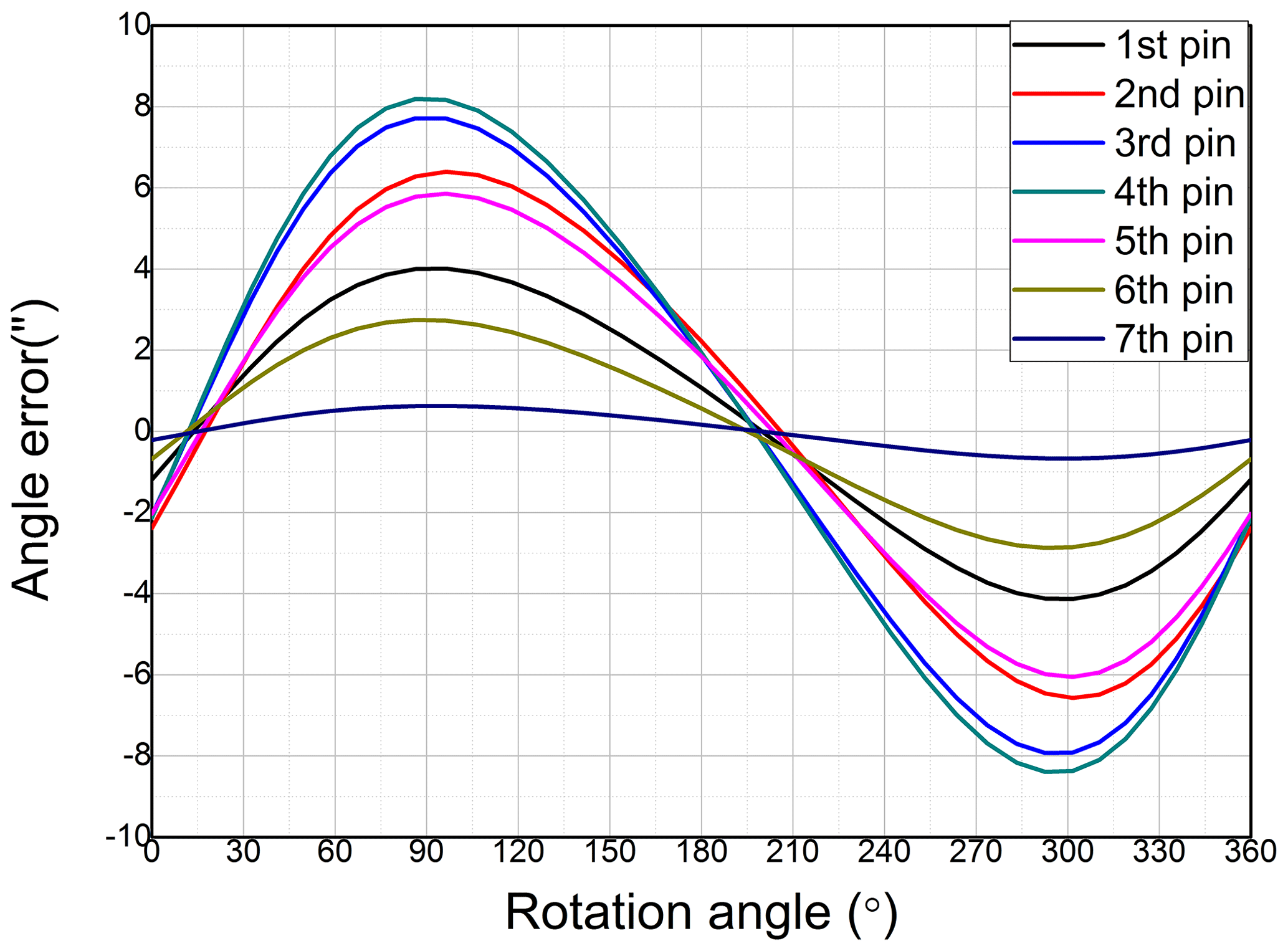
The values obtained using the FEM model are presented in Fig. 9. It has a periodic shape, and there is no difference in the angle error at approximately 15 and 200∘, and the difference in the angle error is maximum at approximately 90 and 300∘, respectively. The results are consistent with those obtained using the angle error equation. However, there is no significant variation in the position of the maximum value for each pin. Further, the value is offset from 0.05 to 0.1 arcsec in the negative direction compared with the angle error equation. Similar to the results obtained via the equation, the difference between the results of the FEM analysis and the angle error equation varies depending on the pin and ranges between −0.55 and −0.14 arcsec. Although there is a slight difference in the rotation angle at which the maximum value is obtained for each pin, the maximum value of the angle error decreases in the order of fourth pin, third pin, fifth pin, second pin, sixth pin, first pin, and seventh pin.

Based on the angle error equation, the angle error is lowest at the first, sixth, and seventh pin, which are at the end of the crankshaft. Moreover, the angle error is largest at the second, third, and fourth pin, which are near the center of the crankshaft. Further, the angle error tends to 0 when the rotation angle is approximately 15 and 200∘, which is the point at which the torsional deformation due to Fv becomes 0. In contrast, the angle error becomes maximum at a rotation angle of approximately 100 and 300∘, where Fv is the maximum. This proves the accuracy of the angle error equation.
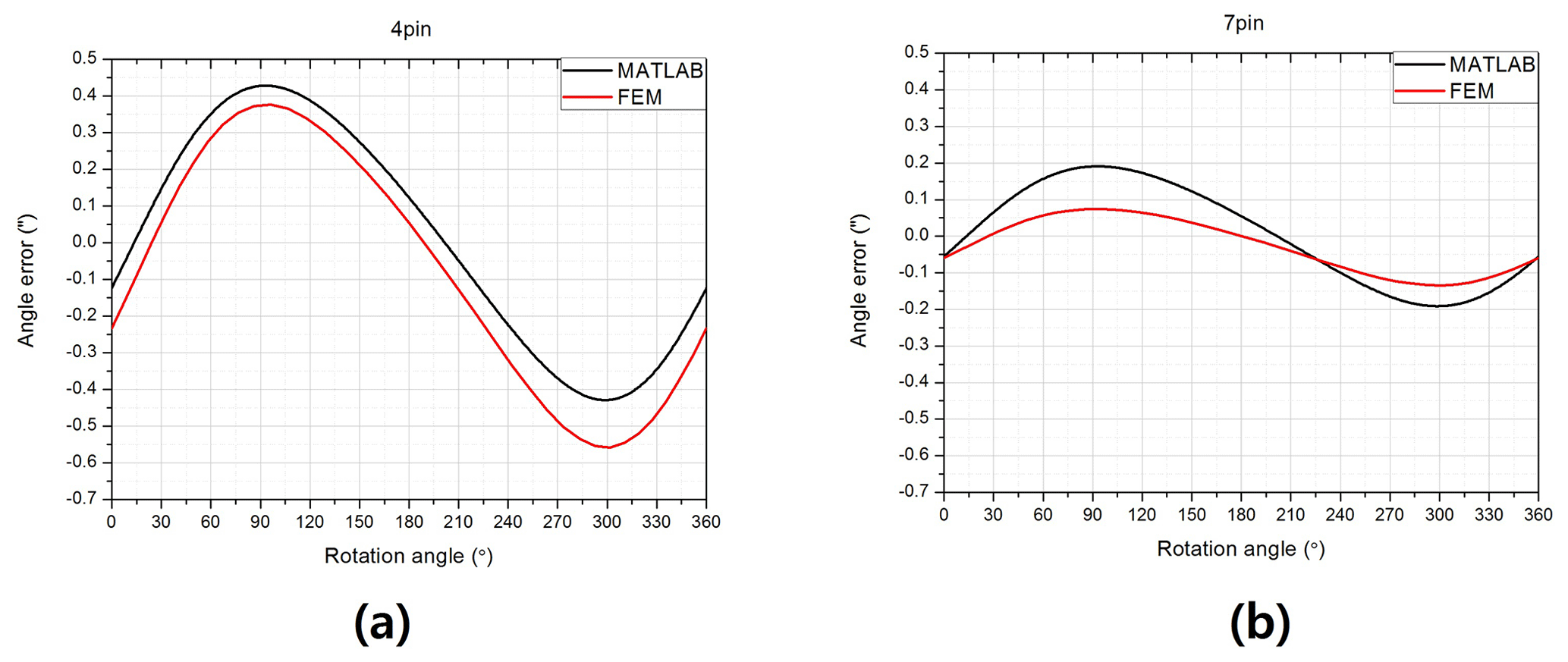
The results of the equation and FEM analysis were compared for all pins. The results of the fourth and seventh pin are presented in Fig. 10, and the results obtained via the equation and FEM analysis are similar. The difference in results between the equation and FEM shows a certain trend, which can be explained as follows:
The results of the second to the fifth pin (near the crankshaft center) obtained via the equation and FEM analysis are similar. However, compared to the graph obtained via the equation, the graph obtained via the FEM analysis is offset in the negative direction, which represents the difference. In contrast, the results of the fist pin and the seventh pin located near the end of the crankshaft are not offset, and the difference in the results of the two methods is due to the amplitude difference. The sixth pin indicates that the results for the middle of the crankshaft and end of the crankshaft are mixed. The difference due to the offset is constant for all rotation angles, whereas the difference in amplitude varies with the position of the rotation angle. Therefore, the maximum difference at a specific rotation angle is largest at the first pin and the seventh pin, with varying amplitudes. However, the difference at the first pin and the seventh pin of the whole rotation angle is not larger compared to the other pins.
As mentioned earlier, two types of phenomena occur due to the difference in offset distance amplitude. The fundamental cause of the two tendencies is that the structure of the crankshaft changes due to bending. Despite the bending of the crankshaft not being considered in the angle error equation, the bending phenomenon occurs in the crankshaft through Fu and Fv in practice.
The process by which the bending of the crankshaft affects both types of phenomena can be deduced as follows. First, the offset phenomenon occurs due to the deformation of the crankshaft through bending, Fu and Fv, and the applied torque (T) change. This is demonstrated by the offset phenomenon not occurring at the end of the crankshaft, where the bending effect is small. However, the offset phenomenon occurs in the middle of the crankshaft, where the bending effect is large. Second, the phenomenon of the amplitude difference occurs because the torque distribution varies because of the deformation of the crankshaft. TH and TT are obtained using the angle error: ϕtotal_H=ϕtotal_T and TG=TH+TT. ϕtotal_H or ϕtotal_T will become inaccurate if the structure is deformed by bending. For instance, when grinding the first pin near the headstock, ϕtotal_H was relatively accurate but ϕtotal_T was inaccurate because of the bending of the crankshaft. Therefore, the error occurs due to the distribution of TH and TT, which is caused by the amplitude difference. For the middle pin, the distribution of TH and TT is accurate because ϕtotal_H and ϕtotal_T have the same error caused by the bending of the crankshaft.
As the difference is caused by the bending of the crankshaft, reducing the bending of the crankshaft results can lower the difference between the results obtained via the equation and FEM. In this study, the crankshaft was fixed to the headstock and tailstock only. However, as the bending of the crankshaft is reduced by steady rests in actual grinding, the actual angle error will be more consistent with the angle error obtained from the analysis using the equation compared to the one using FEM analysis.
Further, the angle error obtained from previous studies, which includes the bending of the crankshaft, and the one that excludes the bending is compared. By comparison, the angle error in this study represents 5 % of the angle error obtained in previous studies. It suggests that the error due to actual torsional deformation is significantly lower than previously considered.
As a result of the verification of the angle error equation as proposed in this paper, there was a small error in the result of the analysis using the equation and FEM, which suggests that the equation is consistent with the prediction of the angle error. Similarly, the value obtained in this study is lower than the error due to bending, but the cause of the error must be accurately separated.
When grinding a crankshaft, the grinding force leads to errors. It is yet to be accurately established whether the error is due to torsional deformation or bending deformation. In this study, the error due to torsional deformation was predicted using the angle error equation, which was formed considering the grinding force, the structure of the crankshaft, and the distribution of torque. The equation was validated through a comparison of the results achieved with the results of the FEM analysis.
-
The results obtained via the equation and the FEM analysis were consistent, which suggests that the angle error equation can accurately calculate the angle error.
-
The results obtained via the two methods had two differences. One difference was the amplitude near the crankshafts’ ends, and the other was the offset phenomenon near the center of the crankshaft.
-
Bending of the crankshaft resulted in an error in the angle error equation.
-
The angle equation could be more accurate if the bending of the crankshaft were reduced using steady rests.
-
The correct angle error due to torsional deformation was 5 % of the angle error obtained from previous studies.
Further studies are required to investigate how the bending of the crankshaft affects the error of the angle error equation.
All the data used in this paper can be obtained from the corresponding author upon request.
JJ analyzed the data, developed the model, and wrote the manuscript; WCC contributed to the guidance of the research and the revision of the manuscript.
The authors declare that they have no conflict of interest.
This paper was edited by Kheng Lim Goh and reviewed by two anonymous referees.
Badger, J. A. and Torrance, A. A.: A comparison of two models to predict grinding forces from wheel surface topography, Int. J. Mach. Tool Manu., 40, 1099–1120, https://doi.org/10.1016/S0890-6955(99)00116-9, 2000. a
Durgumahanti, U. S. P., Singh, V., and Rao, P. V.: A new model for grinding force prediction and analysis, Int. J. Mach. Tool Manu., 50, 231–240, https://doi.org/10.1016/j.ijmachtools.2009.12.004, 2010. a
Huan, J. and Ma, W.: Method for graphically evaluating the workpiece's contour error in non-circular grinding process, Int. J. Adv. Manuf. Tech., 46, 117–121, https://doi.org/10.1007/s00170-009-2074-z, 2010. a
Jang, J. and Choi, W. C.: Error Compensation Using Variable Stiffness in Orbital Grinding, Int. J. Precis. Eng. Man., 19, 317–323, https://doi.org/10.1007/s12541-018-0039-6, 2018. a
Keferstein, C. P., Honegger, D., Thurnherr, H., and Gschwend, B.: Process monitoring in non-circular grinding with optical sensor, CIRP Annals, 57, 533–536, https://doi.org/10.1016/j.cirp.2008.03.133, 2008. a
Li, J., Qian, H., Li, B., and Shen, N.: Research on the influences of torsional deformation on contour precision of the crank pin, Advances in Manufacturing, 3, 123–129, https://doi.org/10.1007/s40436-015-0108-3, 2015. a, b, c, d, e
Malkin, S. and Guo, C.: Grinding technology: theory and application of machining with abrasives, 2nd Edn., Industrial Press Inc., New York, USA, 2008. a
Oliveira, J. F. G., Silva, E. J., Guo, C., and Hashimoto, F.: Industrial challenges in grinding, CIRP Annals, 58, 663–680, https://doi.org/10.1016/j.cirp.2009.09.006, 2009. a
Shen, N., He, Y., Wu, G., and Tian, Y.: Calculation model of the deformation due to grinding force in crank pin non-circular grinding, Int. Ice. Conf. Eng., 1325–1330, https://doi.org/10.1049/cp:20060972, 2006. a
Shen, N., Li, J., Ye, J., Qian, X., and Huang, H.: Precise alignment method of the large-scale crankshaft during non-circular grinding, Int. J. Adv. Manuf. Tech., 80, 921–930, https://doi.org/10.1007/s00170-015-7073-7, 2015. a
Tönshoff, H. K., Karpuschewski, B., Mandrysch, T., and Inasaki, I.: Grinding process achievements and their consequences on machine tools challenges and opportunities, CIRP Annals, 47, 651–668, https://doi.org/10.1016/S0007-8506(07)63247-8, 1998. a
Walsh, A. P., Baliga, B., and Hodgson, P. D.: Force modelling of the crankshaft pin grinding process, P. I. Mech. Eng. D-J. Aut., 218, 219–227, https://doi.org/10.1243/095440704322955768, 2004. a
Yu, H., Xu, M., and Zhao, J.: In-situ roundness measurement and correction for pin journals in oscillating grinding machines, Mech. Syst. Signal Pr., 50, 548–562, https://doi.org/10.1016/j.ymssp.2014.05.009, 2015. a
Yu, H. X., Zhang, Y., Pan, X. H., and Xu, M. C.: New approach for noncircular following grinding of crankshaft pin, Adv. Mat. Res., 497, 46–55, https://doi.org/10.4028/www.scientific.net/AMR.497.46, 2012. a
Zhang, M. and Yao, Z.: Force characteristics in continuous path controlled crankpin grinding, Chin. J. Mech. Eng., 28, 331–337, https://doi.org/10.3901/CJME.2015.0107.007, 2015. a