the Creative Commons Attribution 4.0 License.
the Creative Commons Attribution 4.0 License.
 | 18 May 2021
Structure optimization of a pipetting device to improve the insertion effect of tips
Zeng Huang
Chenxue Wang
Qian Su
Zhiping Lian
In order to solve the problems of the failure of disposable tip insertion which happens in the pipetting process of most multi-station and high-throughput pipetting devices, this paper proposes a high-rigidity screw-type pipette shaft–disposable tip assembly mechanism with excellent auto-centering effects based on the principle of the ball screw drive. The stiffness model of the new pipetting device is established, and its stiffness and axial deformation are analyzed. This new mechanism was introduced to a multi-station and high-throughput pipetting workstation, and the process of pipetting disposable tips is simulated by ANSYS software. The analytical results show that the stiffness value of the new pipetting device is approximately 90 N/µm, and the amount of deformation of the z-axis manipulator is reduced by about 60 % compared to the original pipetting device. Finally, physical verification of the prototype was carried out in the work. The test results show that the new pipetting workstation can increase the tightening rate of the tips by approximately 12 % after optimization when 96 tips are inserted in a single press. In addition, the pass rate of the tightness test of the optimized pipetting workstation has increased by approximately 20 %.
- Article
(2940 KB) - Full-text XML
- BibTeX
- EndNote


An automatic pipetting device can be used for automatic preprocessing of liquid samples in clinical experiments to reduce experimenters' repetitive working strength, shorten the experimental duration and prevent high-risk samples from causing harm to experimenters (Y. Yao et al., 2013; He, 2011). The pipette shaft will be inserted into the disposable tip vertically before each pipetting, shown in Fig. 1a. As we all know, in many biochemical detection and analysis operations, for the reliability, uniformity and repeatability of the numerical results, it is required that the solution filling volume must be accurate and consistent in the filling operation. The airtightness of the tip assembly is the primary factor that affects the accuracy of the solution filling volume. It can be seen that the effect of the tip insertion not only affects the airtightness of the pipette, but also affects the accuracy of the entire liquid analysis system. Experimental results for multi-channel automatic pipettes show that it is hard to put tips on the pipette shaft uniformly and firmly. Most multi-position high-throughput pipetting workstations currently in the market often adopt multiple pipette shaft–tip assembly to ensure a good insertion effect. However, multiple assembly will produce a huge shock between tips and the pipette shaft, reducing the accuracy and causing damage to the pipette workstation.
Research on pipetting systems and pipetting instruments has never stopped. Many companies, scientific research institutions and university laboratories in the field of pipetting have conducted a lot of relevant investigations. Allison et al. (1990) designed an automatic device for repeated dispensation of a precisely controlled amount of fluid. Then Engström and Meiselman (1992) proposed an improved design of molten glass beads based on the same principle, which eliminates the problem of glass bead movement and uses the heat-induced extension and retraction of the heating wire in the performance of the pipetting device. Dutka et al. (2016) proposed a novel microfluidic junction that reduces the dependence of the volume of droplets on the rate of injection. This method can decompose a small amount of liquid sample into nanoliter droplets without generating any dead volume. In the same year, Momotenko et al. (2016) demonstrated the ability of nanopipettes to construct complex free-standing three-dimensional nanostructures using a simple double-barrel nanopipette device.
Some breakthroughs have also been made in the design of controllable automatic pipetting devices. The digital pipetting workstation designed by Xie and Fang (2017) can be applied to the controllable automatic titration of micro-liquid through digital control to solve the problem of repetitive manual withdrawal of the solution and expulsion of the solution. The new-type pipetting device designed by Li and Li (2019) can be used for the automatic installation of eight pipette tips, withdrawal of the solution, expulsion of the solution and discarding of the tip under the coordinated control of a 3D mechanical arm. Liu et al. (2013) have developed a fully automated device for simultaneous detection of four pipettes. This device can be applied to automatic detection. CapitalBio Corporation's Lab Keeper eight-channel automatic pipetting workstation is suitable for liquid distribution, including for the extraction of blood to nucleic acids, but it supports arbitrary selection in two, four and eight channels only. The SF3 automatic pipetting station independently developed by the Shanghai Utrao Medical Instrument Co., Ltd. fails to complete the assembly of all 96 pipette tips (Liu et al., 2012). The EpMotion85075 TMX recently rolled out by Eppendorf Switzerland can be used for complex purposes such as multiple proportions of dilution, random sample application, cell culture and nucleic acid isolation and purification by the paramagnetic particle method (Wu et al., 2016). The Freedom EVO8 automatic liquid handling workstation, developed by TECAN Switzerland, provides four workbenches of different capacities, including 75, 100, 150 and 200 cm. Every workbench is available for accurate and reliable liquid handling and easy-to-use automatic operations (Chen et al., 2015). As the global leader in the pipetting industry, RAININ rolled out a semi-automatic 6/384-hole pipette with interchangeable pipette tips called “BenchSmart 96”. As a combination of single-channel pipettes that boasts automation and manual control, the device can be used to quickly and accurately handle multiple liquids in various ways such as liquid transfer, liquid separation, dilution and mixture.
To sum up, in recent years, many scholars have mostly focused on the method of micro-feeding pipettes, the application of pipettes in biochemical testing, pipetting control technology, pipetting system maintenance and pipette verification methods. However, there has not been too much research on the effect of bulk tip insertion and the airtightness of pipette tips of high-throughput liquid workstations. Although some scholars have proposed loading the tip by vibration, some companies use the method of gently rotating the tip after the tip is put on the sleeve to ensure the tightness of the pipette, but this method is not suitable for a multi-station high-throughput liquid workstation. As shown in Fig. 1b, the traditional multi-station high-throughput triaxial automatic pipetting device adopts straight plug-in tip insertion, by which the z-axis motor of the mechanical arm presses the pipette down for the bulk plug-in mounting of pipette tips. For a single pipette tip or four-/eight-channel low-throughput plug-in mounting of pipette tips, a good plug-in mounting effect can basically be achieved. However, for 96 channels or 384 channels, a large reaction force will apply to the pipetting shaft when inserting the tips in large quantities, which can be seen in Fig. 1a. As a result, the mechanical arm will be warped and tilted shown in Fig. 2, subsequently leading to a difficult concentric insertion of the suction disposable tips and failure of the tip-pipetting shaft assembly. Therefore, this paper proposes a high-rigidity screw-type pipette shaft–disposable tip assembly mechanism in order to solve the problem of the straight plug-in tip insertion method. In combination with a cam guide mechanism, a z motor, a z-axis screw and a z-axis guide slider, the high-rigidity and self-aligning ball screw pair was developed for the design of the new pipetting device, whereby the fixed end of the ball screw–nut pair will be able to be converted during the working process.
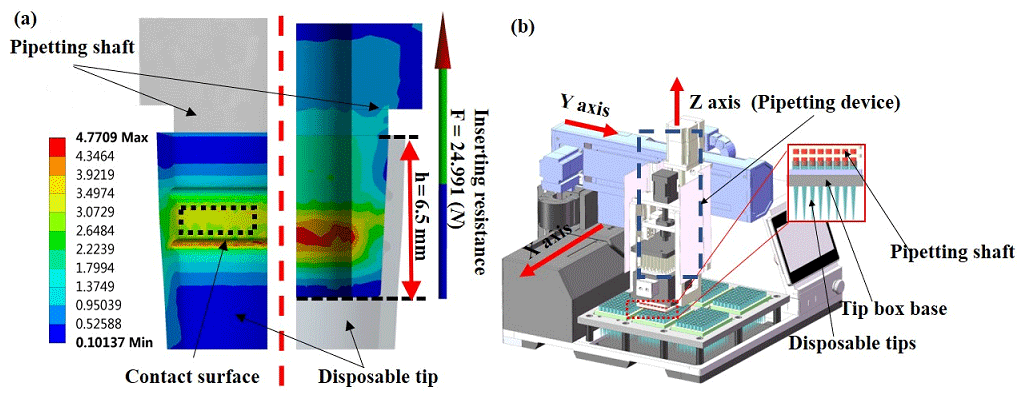
Figure 1(a) Simulation nephogram of a pipetting shaft–tip assembly. (b) 3D diagram of a multi-station high-throughput automatic pipette.

2.1 Development of the device and working principle description
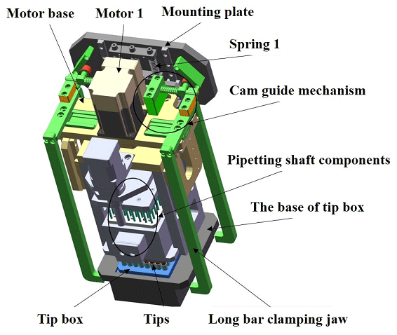
The new pipetting device designed in this study uses the improved ball screw–nut pair as the execution part. It is mainly composed of a z-axis motor, a z-axis lead screw, a z-axis guide rail slider, a lead-screw-type tip insertion unit and other auxiliary components. The schematic diagram is shown in Fig. 3, and the structure of the lead-screw-type tip insertion unit is shown in Fig. 4.
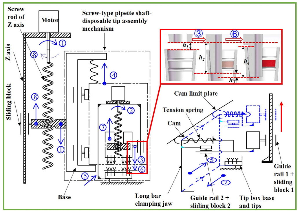
Figure 3The workflow of the new pipetting device. ① The tip insertion unit drops. ② The shaft begins to press and insert the tip. ③ The shaft is blocked and stops dropping after pressing down 8.5 mm. ④ The mounting block of motor 1 rises. ⑤ The long pole clamping jaw rises and retracts. ⑥ The shaft presses and inserts the tip again. ⑦ The shaft and the tip rise, while the long pole clamping jaw drops and stretches out. ⑧ The tip insertion unit rises, and the whole process ends.
The working process is as follows:
-
The z-axis motor turns forward, and the lead-screw-type tip insertion unit is lowered to about 2 mm from the upper end of the tip under the action of the z-axis lead screw and the z-axis guide rail slider.
-
Motor 1 turns forward, and the motor mounting seat can be regarded as a fixed end under the joint action of spring 1 and the substrate convex platform. The shaft assembly is lowered as the moving end to start the pre-insertion of the tip in batches.
-
As can be seen from Fig. 1a, in the later stage of tip insertion in batches, the resistance to the shaft assembly is much greater than the tension of spring 1; therefore, the shaft assembly stops pressing after pressing down by 8.5 mm.
-
The fixed end of the lead-screw-type head insertion unit begins to change, and the shaft assembly will act as the fixed end, while the motor mounting seat is forced to move upward as the moving end.
-
As can be seen from Fig. 4, during the rising process of the motor mounting seat, the long pole clamping jaw will retract while rising under the action of the cam guiding part to the side convex platform of the bottom seat of the tip box, and then the motor mounting seat will stop rising.
-
The fixed end of the lead-screw-type tip insertion unit is changed again, and the motor mounting seat is used as the fixed end, and the shaft assembly is used as the moving end again to continue pressing down the 1.0 mm tip until all tips are inserted completely.
-
Motor 1 reverses, the shaft assembly and the tip rise and the motor mounting seat drops. At the same time, under the action of the cam guiding part, the pole clamping jaw drops while stretching out.
-
Finally, the z-axis motor reverses, and the lead-screw-type tip insertion unit rises under the action of the z-axis guide slider. At this point, the tip insertion is completed, and the next step of liquid extraction can be performed.
2.2 Stiffness analysis
2.2.1 Calculation of axial stiffness
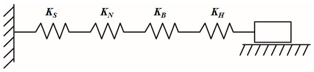
As can be seen from Figs. 3 and 4, the new pipetting device is connected to the lead-screw-type tip insertion unit through three parts including guide rail 1, slider 1 and spring 1. In the process of tip insertion in batches, the acting force between various components is always changed between the lead-screw-type tip insertion unit and the tip box. Especially when the resistance for the tip insertion is large in the late stage, the insertion reaction forces all act on the bottom seat of the tip box, while the load and deformation of the z-axis are almost negligible; therefore, the stiffness of the lead-screw-type tip insertion unit determines the transmission stiffness of the entire device. According to the mounting mode of the ball screw, the axial stiffness model can be simplified, as shown in Fig. 5. According to the stiffness model diagram shown in Fig. 5, the axial stiffness of the new pipetting device is represented by a spring constant K1 and is calculated as per Eq. (1) (Wang et al., 2013).
where KS refers to the axial stiffness of the ball screw, in newton per micrometer (N/µm); KN refers to the axial stiffness of the shaft assembly, in N/µm; KB refers to the axial stiffness of the bearing, in N/µm; and KH refers to the axial stiffness of the long pole clamping jaw and the supporting part, in N/µm.
In this study, the ball screw–nut pair of the tip insertion unit is mounted by supporting one end and fixing the other end, so the axial stiffness KS of the ball screw can be calculated according to Eq. (2) (Song, 2014). The axial stiffness of the shaft assembly mainly includes the axial stiffness of the ball and screw in the shaft assembly and the axial stiffness of the threaded raceway of the nut. Due to the good stiffness of the nut, the nut seat and other parts, and with little deformation, it is only necessary to consider the elastic contact deformation of the ball and the raceway surface. According to Hertz contact theory, the axial elastic deformation amount δN between the ball and the threaded raceway can be calculated as per Eq. (4) (Hu et al., 2014), and its axial stiffness can be calculated as per Eq. (6). The bearing support stiffness is related to the type of bearings used; this design uses the typical angular contact ball bearing, and the axial stiffness of the bearing can be calculated according to Eq. (7). The stiffness of the nut support has been calculated by multiplying the nut stiffness by a factor of 0.8, while the requirements for the stiffness of other supporting parts can be met by using a high-stiffness supporting part, and finally, the stiffness of the long pole clamping jaw can be calculated according to Eq. (10).
where A1 refers to the cross-sectional area of the ball screw with the minimum diameter, in square millimeters (mm2); d refers to the small diameter of the ball screw thread, in millimeters (mm); E1 refers to Young's modulus of elasticity of the ball screw material (GCr15), N/mm2; L refers to the length of the lead screw, in mm; a1 refers to the contact angle of the ball, in degrees (∘); F refers to the axial load, in newton (N); do refers to the ball diameter, in mm; Z1 refers to the number of balls with effective load per turn, in pieces (pcs.); Dm refers to the nominal diameter of the screw–nut, in mm; φ refers to the angle of spiral rise, in ∘; K refers to the theoretical axial stiffness of the nut at 10 % of the rated dynamic load, in N/µm; Ca refers to the rated dynamic load of the nut, in N; Fao refers to the pre-pressing load of the bearing, in N; δao refers to the amount of elastic axial displacement caused by the pre-pressing load of the bearing, in µm; Q refers to the load applied to one rotor of the bearing, in N; Z2 refers to the number of balls of the bearing, in pcs.; a2 refers to the contact angle of the bearing, in (∘); Da refers to the ball diameter of the bearing, in mm; E2 refers to Young's modulus of elasticity of the long pole clamping jaw material (45# steel), N/mm2; A2 refers to the cross-sectional area of the thinnest part of the long pole clamping jaw, in mm2.
2.2.2 Torsional stiffness
The torsional stiffness of the lead-screw-type tip insertion unit reflects its ability to resist torsional deformation, and it mainly includes the torsional stiffness of elastic components such as the ball screw, the bearing seat, motor 1 and other parts. According to the torsion theory, the torsional stiffness of the tip insertion unit can be expressed by the constant KTW and can be calculated as per Eq. (11) (Wang et al., 2013).
where KT refers to the torsional stiffness of the ball screw, in newton millimeters per radian (N mm/rad); K∅1 refers to the torsional stiffness of the bearing seat, in N mm/rad; and K∅2 refers to the torsional stiffness of motor 1 and other parts, in N mm/rad.
Since the torsional stiffness of the bearing seat, motor 1 and other parts is very large, that is, , , the main factor affecting the torsional deformation of the lead-screw-type tip insertion unit is the ball screw, and the torsional stiffness can be calculated as per Eq. (12).
where θ refers to the torsion angle, in rad; M refers to the torque received by the lead-screw-type tip insertion unit, in N mm; x refers to the installation span of the ball screw, in mm; G refers to the modulus of elasticity in shear of the ball screw material, N/mm2; JP refers to the torsional moment of inertia of the section, in cubic millimeters (mm3); d refers to the small diameter of the ball screw thread, in mm.
2.2.3 Transmission stiffness
In this design, under the action of the axial load F, the axial elastic deformation produced by the lead-screw-type tip insertion unit is δ1, as shown in Eq. (14). The torsional deformation produced is θ, as shown in Eq. (15); and this torsion angle is converted into the axial deformation amount of the tip insertion unit as δ2, as shown in Eq. (16) (Jiang et al., 2012). Therefore, the overall axial deformation δ of the entire tip insertion unit is shown in Eq. (17). Finally, it can be deduced from the formula that the transmission stiffness of the new pipetting device is shown in Eq. (18).
where F refers to the axial load, in N; K1 refers to the axial stiffness of the lead-screw-type tip insertion unit, in N/µm; M refers to the torque received by the lead-screw-type tip insertion unit, in N mm; KT refers to the torsional stiffness of the ball screw, in N mm/rad; t refers to the lead of the ball screw, in mm; K refers to the transmission stiffness of the new pipetting device, in N/µm.
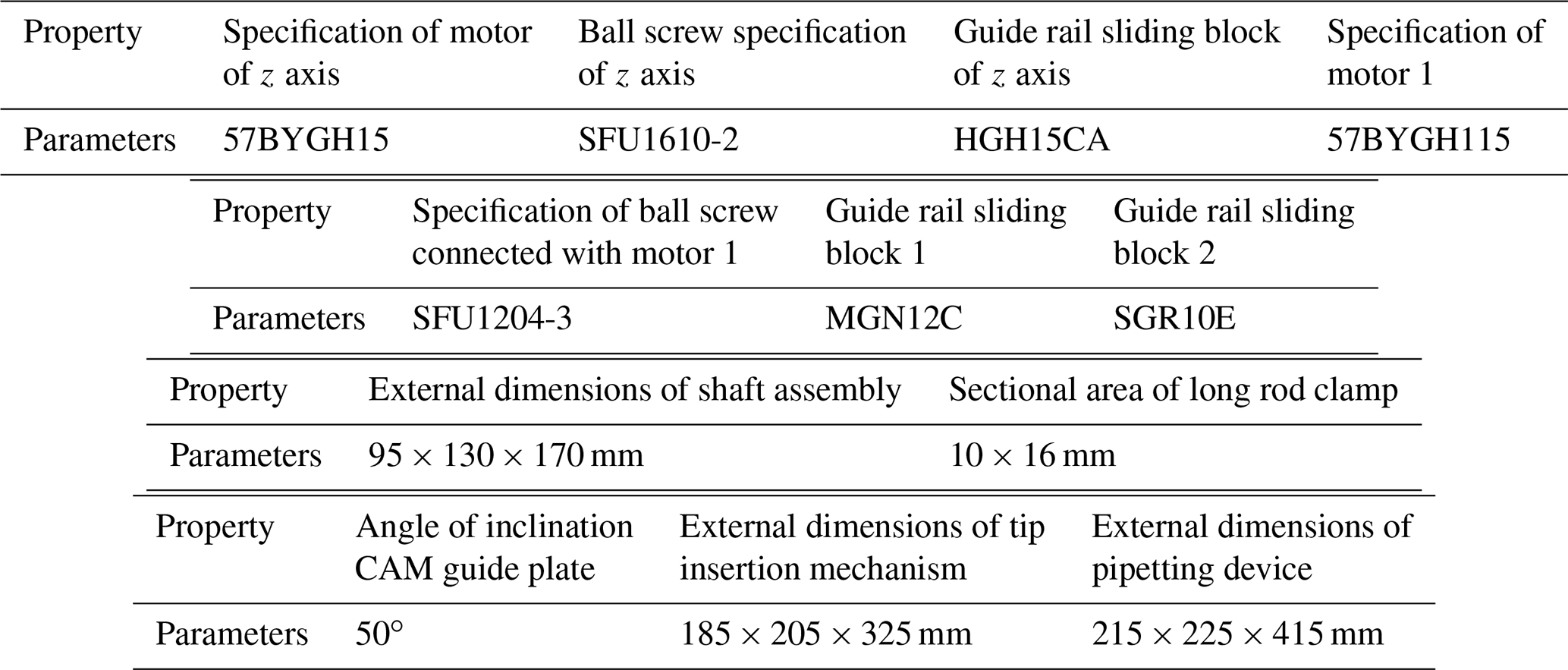
As can be seen from Fig. 1a, the maximum resistance received by the a single pipetting shaft is 24.991 N when the tip is inserted, and as the new pipetting device optimized in this study features 96 channels, that is, when 96 tips are inserted in batches, the total resistance received by the pipetting shaft is approximately 2400 N. Therefore, according to the magnitude of the total thrust required for inserting the tip into the pipetting shaft, the motor and screw specifications of the lead-screw-type tip insertion unit are selected and calculated, and through checking and verification, it is determined that the nominal diameter of ball screw is 12 mm, the lead is 4 mm, the screw thread length is 60 mm, the total length of the lead screw is 80 mm, the motor specification model is 57BYGH115, the holding torque is 28 kg cm, the step angle is 1.8∘ and the rotational moment of inertia is 811 g cm2. Finally, by substituting the above parameter values into Eqs. (1) to (18), it can be calculated that KS=161.71/(N/µm), KN=699.85/(N/µm), KB=334.54/(N/µm), K1=94.34/(N/µm), /(N mm/rad), K=90.069 (N/µm) and δ≈0.04274 mm. It can be seen that, as the stiffness of the new pipetting device is very high, the deformation in the process of installing the tip in batches is relatively small. In addition, in this study, the downward pressing force of the pipetting sleeve assembly is balanced by the pulling force applied to the tip placement box by the inserting mechanism and will not be transmitted to the carrying mechanism of the pipetting workstation through the lifting plate, which will deform the carrying mechanism. And it affects the insertion effect of the tip head. The advantages of the above-mentioned new pipetting workstations provide a technical guarantee for improving the effect of tip insertion. The specification parameters of critical components are shown in Table 1.
Table 1The specification of critical components of the new pipetting device.
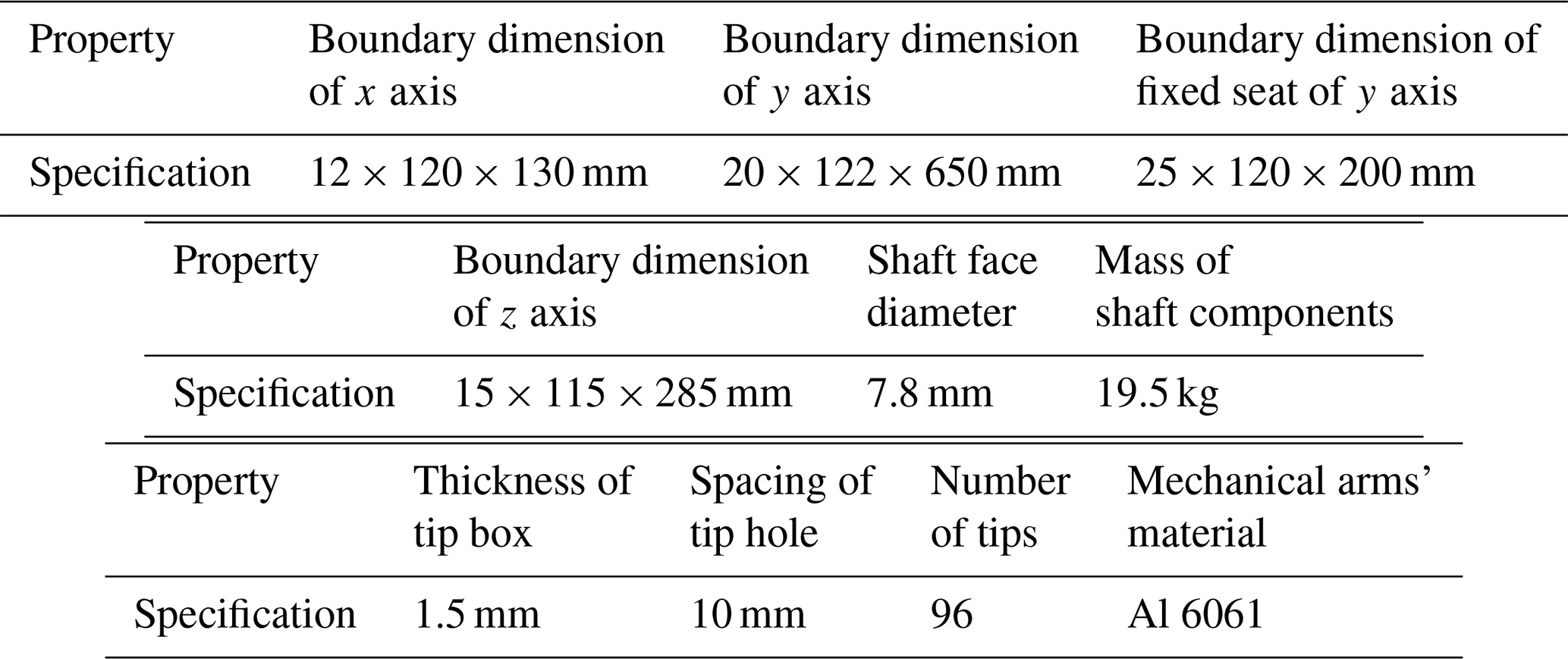
According to the investigation, it is found that the mechanical arm of a conventional multi-station high-throughput automatic pipetting device is prone to warp when the tip is inserted in batches, so that the tip box is deformed non-uniformly. As a result, it is difficult to achieve concentric insertion of the tip and the shaft, and it is difficult to achieve equal depth depression between the shafts, leading to the failure of the tip insertion. Therefore, to verify the superiority of the new pipetting device, this study takes the multi-station high-throughput automatic pipetting device manufactured and used by a company in 2019 as an example to optimize and improve, simulates the process of in-batch insertion of tips in the pipetting device and conducts the selective analysis on warping deformation of the mechanical arm, the pressing-down depth of the shaft and the deformation of the tip box before and after optimization. The detailed parameters of the analysis are shown in Table 2.
Table 2Detailed parameters of the simulation assembly process.
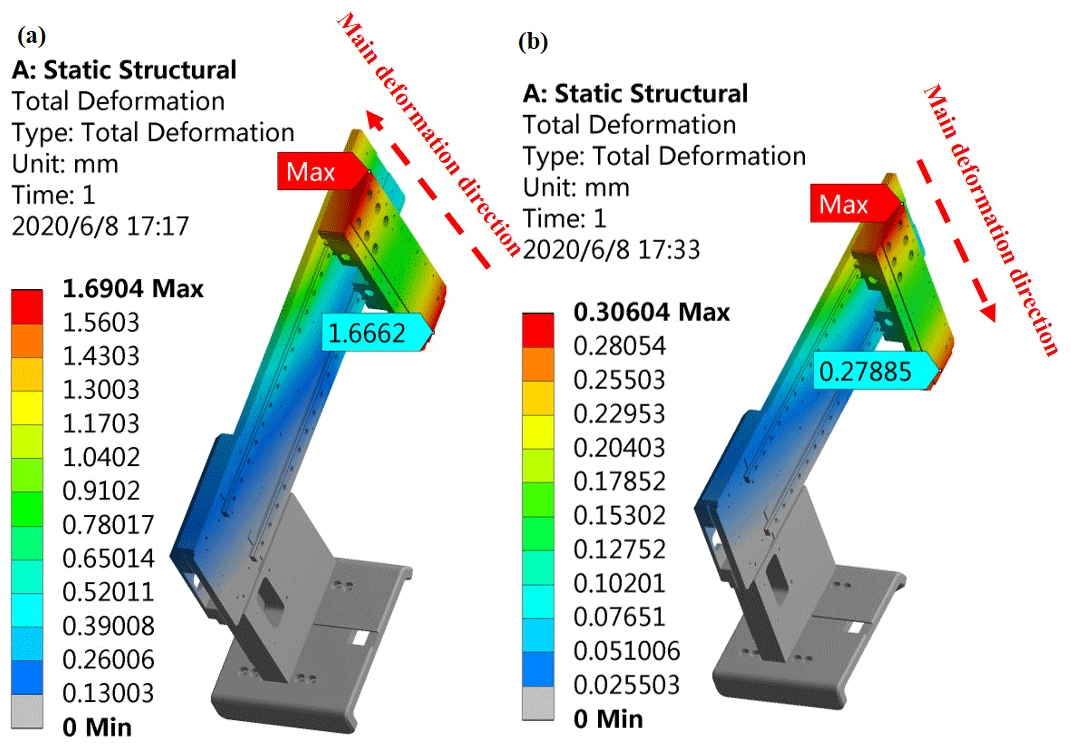
3.1 Comparison of warping deformation of the mechanical arm before and after optimization
Since the pipetting station often needs to complete the multi-station moving action, its rack structure is limited to the three-dimensional mechanical arm form in the mode of the Cartesian coordinate system. Figure 6a shows a simulation cloud diagram of the deformation of the mechanical arm during in-batch insertion of the tip before optimization, and its force diagram is shown in Fig. 2. The mechanical arm can be approximately simplified into the form of a cantilever beam; thus, the maximum warpage deformation of the mechanical arm is about 1.69 mm. However, for a lead-screw-type tip insertion unit, during the process of in-batch insertion of tips, since the tip insertion part is in elastic contact with the mechanical arm, the reaction force acting on the mechanical arm during the insertion is almost negligible. As shown in Fig. 6b, the deformation of the mechanical arm is almost negligible, and the deformation is caused only by the gravity of the z-axis pipetting device before insertion and has no influence on the subsequent insertion of the shaft and the tip.
3.2 Comparison of pressing-down depth of pipetting shaft
As can be seen from Fig. 1a, in the process of assembling the shaft and the tip, the maximum resistance occurs at the late stage of insertion, and at this stage, the shaft needs to be pressed down by 1 mm again before the tip is fully assembled and the insertion work is completed. Therefore, this study mainly analyzes the pressing-down condition of the shaft at this stage. The pressing-down condition of the pipetting shaft before optimization is shown in Fig. 7a, and the simulation result of the pressing-down condition of the shaft of the new pipetting device after optimization is shown in Fig. 7b. Through comparison, it can be seen that the shaft pressing-down depth of the new pipetting device is uniform. The maximum pressing-down depth of the shaft is 1.0291 mm, while the minimum pressing-down depth is 0.99612 mm, and the maximum difference of pressing-down depth between the shafts is only 0.033 mm. The pressing-down depth of all shafts is almost the same, indicating that each shaft will be tightly fitted with the corresponding tip lock when motor 1 stops. However, before optimization, the maximum pressing-down depth of the shaft is 1.134 mm, and the minimum pressing-down depth is 0.64703 mm. The maximum difference of the pressing-down depth is 0.486 mm; that is, the difference of the pressing-down depth of the pipetting shaft is large, which may easily lead to failure of the insertion of part of the tip.
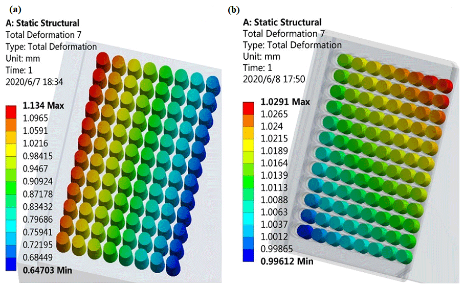
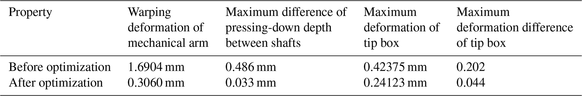
Table 3Comparison of in-batch insertion effect of tip before and after optimization.
3.3 Comparison of deformation of tip box
According to the investigation, the deformation of the tip box tends to change the position of the tip and then leads to the difficulty of concentric insertion between the tip and the shaft. Figure 8a shows the deformation of the tip box during in-batch insertion of the tip before optimization, while Fig. 8b shows the deformation of the tip box after optimization. Through comparison, it is found that, since the deformation of the tip box during in-batch insertion of the tip for the new pipetting device is uniform and small, the shaft can be inserted concentrically with the tip to ensure the insertion effect of the tip. The deformation before optimization is very uneven, the deformation near the z-axis base plate is large, the maximum deformation is about 0.42375 mm, the outward deformation gradually decreases, by about 0.23116 mm, and the maximum deformation difference is 0.202 mm. Note that a large deformation difference tends to make it difficult for individual tips to be inserted into the shaft.
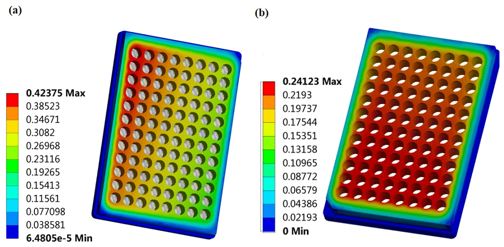
Figure 8Simulation analysis on deformation of the tip box before (a) and after optimization (b).
Table 3 shows the results of simulation of in-batch insertion of the tip of pipetting device before and after optimization. Through comparison, it can be seen that the lead-screw-type tip insertion unit can solve the problem of the poor insertion effect of the existing multi-station high-throughput pipetting station in the process of in-batch insertion of the tip. The warping deformation caused by the mechanical arm is almost negligible, the pressing-down depth of each pipetting shaft is uniform, the effect of the tip insertion is goods and the deformation of the tip box is also uniform. All of the above may ensure that when the pipetting shaft is pressed down, the concentric insertion with the tip is maintained at all times, thus greatly improving the effect of in-batch insertion of the tip.
3.4 Prototype experiment
In this study, a new type of multi-station high-throughput automatic pipette prototype was manufactured based on the above design ideas. The main purpose of this prototype test is to test the inserting effect of tips and airtightness of the tip after assembly.
First of all, this study took the batch insertion of 96 tips as an example to compare and analyze the effect of batch insertion of tips before and after the optimization of the pipetting workstation. When all 96 tips are inserted in a single press, 8–10 tips of the automatic pipette before optimization are not tightly fitted with the sleeve. With a lot of experiments, the statistical record results are shown in Table 4.
Table 4Comparison of the number of tightening tips in single press before and after optimization.

Before optimization, the automatic pipette needs to be pressed down and inserted two–three times to tighten all the 96 tips. After optimization, it only needs to be operated once. The next step is to check the airtightness of the tip assembly. This study adopts the pipette tightness detection method designed by Ma et al. (2008) to judge whether the pipette is sealed under the force of pressure. To be specific, the tightness of the pipette is a combination of the tightness between the pipette piston and the piston seal and the tightness between the pipette sleeve and the tip. The criterion of pipette tightness is that the vacuum degree reaches 0.04 MPa, and it can be kept at this level for at least 5 s without bubbles; otherwise the adhesion is unacceptable. This study tested the 96 channels of the prototype one by one and recorded the length of time each channel can be maintained when the vacuum value is 0.4 MPa. Before optimization, it is only used as a reference for comparison. This article focuses on the specific performance after optimization.
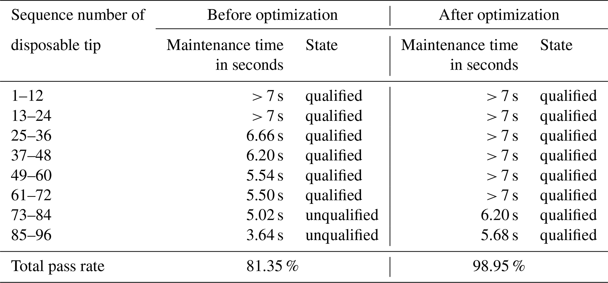
Table 6Statistical table of tightness test results of channels 85–96 after optimization.
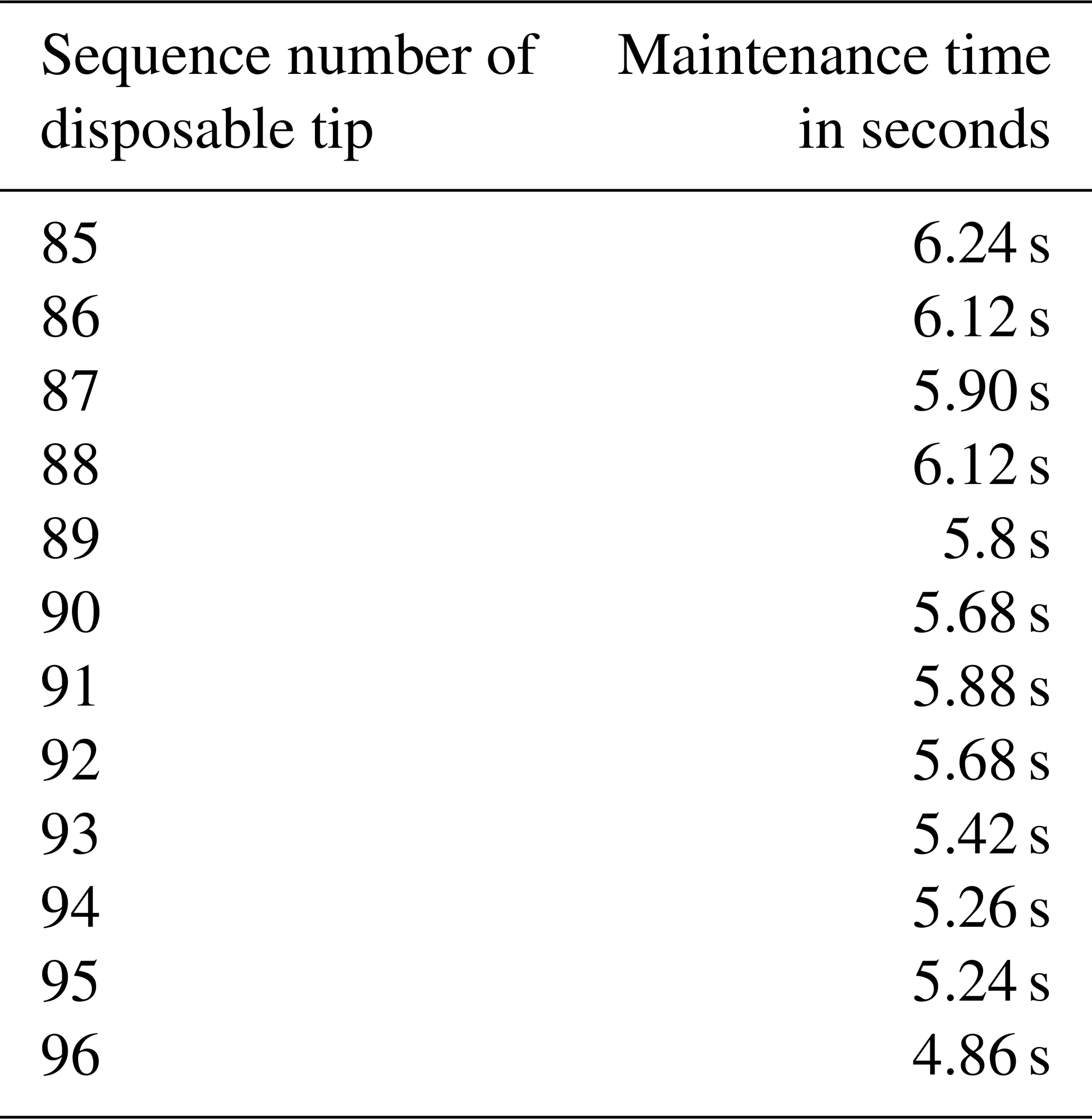
It can be seen from Tables 4, 5 and 6 that in the case of a single insertion of 96 tips, the tightening rate of the tips increased by approximately 12 % after optimization. The maintenance time of the lowest set of channels before optimization is only 3.64 s when the vacuum degree is 0.4 MPa, while the maintenance time of the lowest set of channels after optimization is 5.68 s under the same conditions, and only the maintenance time of the 96th channel is less than 5 s, which is 4.86 s. The above-mentioned prototype test results fully demonstrated that the qualification rate of the tip insertion of the new pipetting workstation has increased by approximately 20 %.
In this paper, a high-rigidity screw-type tip-inserting mechanism with a good centering effect is designed. The structural characteristics and working principle of the inserting mechanism are introduced, the stiffness model of the new-type pipetting device is established and its stiffness and axial deformation are calculated. Finally, a multi-station high-throughput automatic pipette produced by a company was used as an example to optimize and improve it and conduct a prototype test. The research conclusions are given in the following.
The theoretical stiffness of the lead-screw-type tip insertion unit is very large, which is about 90.069 N/µm, and the axial deformation during in-batch insertion of the tip is very small, which is only 0.043 mm.
When the optimized new pipetting device is inserted with the tip, the warpage deformation of the robotic arm of the automatic pipette is of the pre-optimization. The maximum value of the difference in the depression depth between the various pipette sleeves is only 0.03258 mm, which is of that before optimization.
In the case of the new pipetting workstation with 96 tips inserted in a single press, the tightness rate of tip increased by approximately 12 % after optimization; the tightness test pass rate of the optimized pipette workstation increased by approximately 20 %.
The screw-type inserting mechanism in this study has theoretical guiding significance for the design of other such contact loading devices that need to maintain high rigidity and a centering motion.
Data can be made available upon request by contacting Chenxue Wang (wangchenxue2016@email.szu.edu.cn).
ZH and CW puts forward a method to optimize and design the structure of the pipetting device, using finite element analysis. QS and ZL did the final examination of the whole paper. ZH and CW performed the experiment to verify the optimization scheme.
The authors declare that they have no conflict of interest.
This study is supported by funding from the Basic Ability Improvement Project of Young and Middle-aged Teachers in Guangxi Universities, P.R. China (grant no. 2021KY1069).
This research has been supported by the Basic Ability Improvement Project of Young and Middle-aged Teachers in Guangxi Universities, P.R. China (grant no. 2021KY1069).
This paper was edited by Daniel Condurache and reviewed by three anonymous referees.
Allison, J., Bailey, D, M., Johnnie, W., and Mikesell, B.: An automatic micropipette fluid dispenser, Behav. Res. Meth. Ins. C., 22, 517–519, https://doi.org/10.3758/BF03204435, 1990.
Chen, Z., Fang, Y., and Peng, J.: Design and Implementation of Temperature Acquisition System for Polymerase Chain Reaction, Journal of Bionanoscience, 9, 480–483, https://doi.org/10.1166/jbns.2015.1334, 2015.
Dutka, F., Opalski, A, S., and Garstecki, P.: Nano-liter droplet libraries from a pipette: step emulsificator that stabilizes droplet volume against variation in flow rate, Lab Chip., 16, 2044–2049, https://doi.org/10.1039/c6lc00265j, 2016.
Engström, K. and Meiselman, H. J.: Fabrication of glass micropipettes: A semi-automatic approach for trimming the pipette tip, Biorheology, 29, 499–506, https://doi.org/10.1016/j.biomaterials.2012.08.045, 1992.
He, J.: Integration of Laboratory Automation Analyzer and Information System, China Digital Medicine., 06, 99–102, https://doi.org/10.3969/j.issn.1673-7571.2011.08.031, 2011.
Hu, J. Z., Wang, M., and Gao, X. S.: Analysis of axial contact stiffness of pre-positioned double nut Ball screw pair, Chin. J. Mech. Eng., 2014, 66–75, https://doi.org/10.3901/JME.2014.07.060, 2014.
Jiang, S., Wang, S. Y., and Ding, W.: Stiffness analysis of ball screw in feed system of CNC machine tools, Mechanical Engineering and Technology Automation, 000, 88–89, https://doi.org/10.3969/j.issn.1672-6413.2012.06.034, 2013.
Li, J. and Li, Z.: Design and analysis of pipette module for automatic liquid workstation, Anal. Instrum., 2019, 14–18, https://doi.org/10.3969/j.issn.1001-232x.2019.03.003, 2019.
Liu, B., Jia, Y., and Ma, M.: High throughput SNP detection system based on magnetic nanoparticles separation, J. Biomed. Nanotechnol., 9, 247–256, https://doi.org/10.1166/jbn.2013.1483, 2013.
Liu, Z., Deng, Y., and Li Q.: Research of the incubation and hybridization instrument with vibration for nanoparticles, J. Nanosci. Nanotechno., 12, 8448–8452, https://doi.org/10.1166/jnn.2012.6623, 2012.
Ma, M., Yang, X., and Zhou, Q.: Manufacturing and operation method of adhesion test device for pipette, Meas. Tech., 2008, 08–023, https://doi.org/10.3969/j.issn.1000-0771, 2008.
Momotenko, D., Page, A., Maria, A. V., and Patrick, R. U.: Write-Read 3D Patterning with a Dual-Channel Nanopipette, ACS Nano., 10, 8871–8878, https://doi.org/10.1021/acsnano.6b04761, 2016.
Song, W.: Analysis and Research on axial stiffness of ball screw System, Modern Manufacturing Engineering, 2014, 71–75, https://doi.org/10.3969/j.issn.1671-3133.2014.10.015, 2014.
Wang, W., Deng, Y., and Li, S.: A novel acetylcholine bioensor and its electrochemical behavior, J. Biomed. Nanotechnol., 2013, 736–740, https://doi.org/10.1166/jbn.2013.1577, 2013.
Wu, Y., Chen, H., and Chen, Z.: Multifunctional Device for Nucleic Acid Extraction Based on Magnetic Separation and Its Co-Working with Liquid Handling System for High Throughput Sample Preparation, J. Nanosci. Nanotechno., 16, 6919–6924, 2016.
Xie, Z. and Fang, H.: Design and Development of digital pipeting workstation, Mech. Design Res., 33, 188–191, 2017.
Yao, Y., Lu, S., and Liu, Y.: A review on automatic distribution of trace liquid, J. Mech. Eng., 49, 140–153, https://doi.org/10.3901/JME.2013.14.140, 2013.
Yao, Y. F., Zhao, J., and Jia, W.: Development of a high-throughput immunoanalyzer based on chemiluminescence principle, Acta Instrumentae Sinica, 34, 85–93, 2013.