the Creative Commons Attribution 4.0 License.
the Creative Commons Attribution 4.0 License.
 | 23 Apr 2021
Parameter tuning of robust adaptive fuzzy controller for 3D elliptical vibration-assisted cutting
Yongsheng Du
Mingming Lu
Hao Wang
Jiakang Zhou
Jieqiong Lin
Elliptical vibration cutting (EVC), as a precision machining technology, is used in many applications. In precision machining, control accuracy plays an essential role in improving the machinability of difficult-to-machine materials. To improve the control accuracy, dynamic and static characteristics of the system need to be tuned to obtain the optimal parameters. In this paper, we use a glowworm algorithm with an improved adaptive step size to tune the parameters of a robust adaptive fuzzy controller. We then obtain the optimal controller parameters through simulation. The optimal solution of the controller parameters is then applied to a 3D EVC system model for simulation and closed-loop testing experiments. The results indicate that a good agreement between the ideal curve and the tracking signal curve verifies the optimality of the controller parameters. Finally, under certain cutting conditions, the workpieces of three different materials are cut with two different cutting methods. The study revealed that the surface roughness value is reduced by 20 %–32 %, which further verifies the effectiveness of the optimal controller's parameters.
- Article
(2831 KB) - Full-text XML
- BibTeX
- EndNote


Elliptical vibration cutting (EVC) technology was first proposed by Shamoto in 1984 (Ma et al., 2004). For decades, EVC devices evolved from 2D to 3D, and many experiments verified their superiority in the machining of difficult-to-machine materials. Since the 1990s, in-depth research works have been conducted on elliptical vibration cutting and designing EVC devices (Tan et al., 2018; Kim and Loh, 2007; Zhang and Song, 2019). The machinability of difficult-to-process material was also examined in Lu et al. (2017) and Dong et al. (2020), and path planning was reported on in Kim and Loh (2008), Jieqiong et al. (2013) and so on. However, the improvement of control accuracy in the process of 3D EVC is a challenging task, and both the dynamic and static characteristics of the system need to be tuned to obtain the optimal parameters. Precision control also plays a significant role in the machining performance of 3D EVC. Therefore, we use a glowworm algorithm with an improved adaptive step size to tune the parameters for a robust adaptive fuzzy controller.
To meet the control requirements and achieve effective precision machining, suitable controller parameters must be carefully selected. Parameter tuning improves the dynamic and static characteristics of the system by changing the parameters of the control unit to achieve a more efficient control performance. In engineering, different methods, such as the critical proportionality method, response curve method, attenuation curve method (Yang et al., 2012; Verboven et al., 2005; Petkov, 2018), etc., are often used for parameter tuning. However, for complex control systems, the optimal parameters for the tuning of the controller need intelligent optimization algorithms. Instances of such intelligent algorithms are particle group algorithms (Karakuzu, 2010), genetic algorithms (Ortiz et al., 2018), neural network algorithms (Sheng et al., 2017) and various new bionic intelligence algorithms, e.g., bat algorithms (Li et al., 2018; Xue et al.,2015), cuckoo search algorithms (Yildiz, 2012; Gandomi et al., 2011), etc.
Extended research has been done on tuning controller parameters in recent years. Soma et al. (2004) proposed a fictitious reference iterative tuning (FRIT), where only one shot of experimental data is required to perform the offline nonlinear optimization and obtain the optimal parameter of the controller in the real closed loop. The result of the control experiments confirmed the validity of FRIT. García-Gutiérrez et al. (2019) proposed an optimization program based on the cuckoo search (CS) algorithm to optimize all parameters of a fuzzy logic control (FLC) and applied their proposed algorithm to a nonlinear magnetic levitation system. Comparative simulation results were also provided to validate the featured improvement of such an approach, which can be extended to other FLC-based control systems. Nie et al. (2017) proposed an adaptive chaotic particle swarm optimization (ACPSO) to optimize the parameters of the proportional integral derivative (PID) controller. The results of the performance test for their algorithm showed that ACPSO was efficient when used to find the best parameters of the PID controller. Furthermore, Zhu and Liu (2020) conducted extensive studies on machining chatter and presented a novel approach to detect the milling chatter based on variational mode decomposition (VMD) and energy entropy. It was found that the parameters, such as the number of modes (K) and the quadratic penalty (α), need to be empirically selected when the raw signal is decomposed by the VMD. Aimed at solving the problem of selecting K and α, Liu et al. (2018) also presented an automatic selection method of VMDs based on kurtosis. The results show that VMD can be used to effectively decompose the nonstationary signal. When the kurtosis of the reconstruction signal is the largest, the best VMD parameters are obtained.
Although the above article has tuned the controller parameters and further verified the optimality of the controller parameters through simulations and experiments, it has not been applied in the machining experiment, and the effectiveness of the optimal parameters of the controller cannot be obtained more intuitively. In this paper, based on the nonlinear Wiener model of 3D EVC, an improved adaptive step size glowworm swarm optimization algorithm (IASGSO) is used to tune the parameters of the robust adaptive fuzzy controller and obtain the optimal solution of the controller parameters. The optimal solution of the controller parameters is also applied to the 3D EVC device system model for simulation and closed-loop test experiments. Our simulation results verify the optimality of the robust adaptive fuzzy controller parameters. Finally, a copper rod, an aluminum rod and a titanium alloy (Ti6A14V) are machined by 3D EVC and 3D EVC with a robust adaptive fuzzy controller improved by IASGSO. The effectiveness of the control system is also verified by analyzing and comparing the surface morphology and surface roughness values of the produced samples.
2.1 Structure and principle of 3D EVC device
In this paper, the 3D EVC device is a hybrid drive three-dimensional elliptical vibration-assisted cutting device (3D EVC), as shown in Fig. 1. The device of the developed apparatus is mainly composed of two parts, i.e, the upper part and the lower part. The lower part has a compliant mechanism that can be fixed on a lathe by the connecting block. The piezoelectric stack 1 and the piezoelectric stack 2 are also fixed on the lower compliant mechanism, and the piezoelectric stack 3 is fixed on the upper compliant mechanism. For easy analysis, three axes are defined, e.g., the axis along piezoelectric stack 1 is defined as Y1, the axis along piezoelectric stack 2 is defined as Y2, and the axis along piezoelectric stack 3 is defined as X. It should be noted that, for the three piezoelectric stacks, the motions are approximately independent of each other, i.e., there is no transverse motion introduced, which is helpful for extending the life of piezoelectric stacks that is affected by shearing effects. Besides, the 3D elliptical vibration can be obtained when three input displacement signals with different phase shifts are adopted. The displacement signal generated by the piezoelectric stack is acquired by three displacement sensors, which are fixed on the apparatus through sensor holders. As feedback signals, these displacement signals can be used to form a closed-loop control.
The parallel series hybrid driving system is driven by three ballast stacks of two parallels and one vertical with the nonlinear resonance, and the position of the space 3D ellipse is achieved by adjusting the signal parameters of the piezoelectric stack drive. There are three piezoelectric stacks positioned to drive the flexible hinges along three directions, respectively, and there is no coupling between them. At the same time, the X-direction flexible device is driven along the X direction by the piezoelectric stack, and the flexible device in the Y direction is driven by two parallel piezoelectric stacks. By adjusting the phase difference between the driving signals of the two piezoelectric stacks, the X-direction flexible device can generate a two-dimensional elliptical motion track on the YOZ plane, so that the device generates an ideal three-dimensional elliptical motion track.
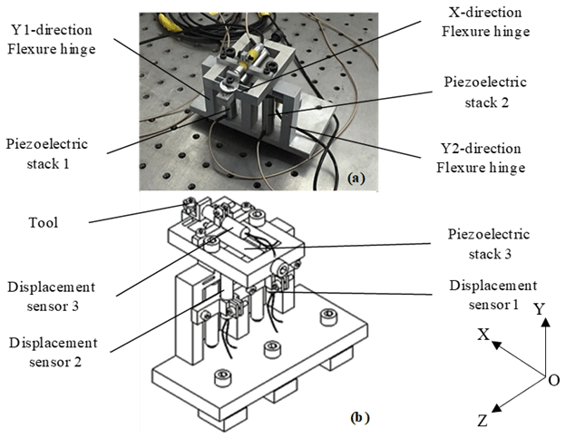
Figure 1The 3D EVC system. (a) Model structure of 3D EVC. (b) Schematic diagram of the 3D EVC.
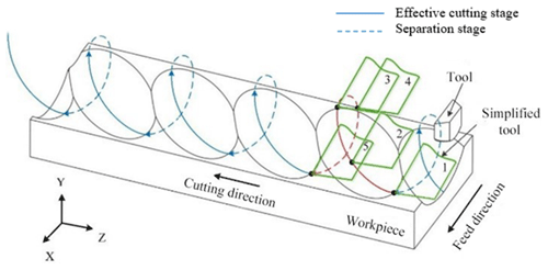
The principle of the 3D EVC is shown in Fig. 2. The concrete cutting principle is the continuous progression of the tool in the process of material removal. Therefore, the movement trajectory of the tool is a three-dimensional elliptical motion. As shown in Fig. 2, points 1–5 represent the position of the tool at different times, which constitutes a complete cutting cycle. It can be divided into two stages, i.e., effective cutting and tool–workpiece separation.
2.2 3D EVC system model
The objective is to achieve the best machining performance and precision control in the precision machining of elliptical vibration cutting. Therefore, a perfect control system is required to be developed to achieve such a precision control. This section focuses on system modeling of the 3D EVC device and identification of the system model.
The nonlinear Wiener system model of the single-input, single-output (SISO) process of 3D EVC can be represented, as in Lu et al. (2019), as follows:
where x(t) represent the output of the linear part, the input of the nonlinear part of the system and the unfathomable output of the dynamic part in the Wiener model. y(t) represent the output of the control system. θ1 and θ2 are the parameter vectors of the Wiener model, φ1(t) and φ2(t) are the information vectors in of the Wiener model, and e(t) is the signal disturbance, which is a zero-mean white noise.
Identification experiments for Eq. (1) use the improved adaptive step size glowworm swarm optimization algorithm (IASGSO). According to Lu et al. (2019), the identification results of the X-direction subsystem of the 3D EVC system are as follows:
where A(q−1) and B(q−1) are nA-order and nB-order polynomials in the backward shift operator, respectively. As shown in Eqs. (3) and (4), q−1 is a delay operator.
2.3 Robust adaptive fuzzy controller
In this section, we propose an improved design of a robust adaptive fuzzy controller for SISO-uncertain nonlinear systems. Consider a class of nonlinearly indeterminate SISO systems that are subject to external disturbances as follows:
where is the system state vector, are the input and output of the control system, fi(⋅) is the unknown smooth nonlinear function, gi(⋅) is the unknown smooth virtual control nonlinear gain function, and is the uncertainty and bounded external disturbance.

Figure 3The IASGSO optimized solution versus the number of iterations for (a) and and (b) ρ2 and ρ3.
Here we define the tracking error, z, which tracks a given reference signal, yr(t), and further assume that the given reference signal, yr(t), is bounded as follows:
According to the hypothesis in Lin et al. (2020), we suppose the system has no zero dynamics and set , and . Equation (5) is then changed to the following:
Considering the three-dimensional elliptical vibration-assisted cutting system as in Yang et al. (2004), we then adopt the SISO nonlinear Wiener system. Therefore, in the following:
where g(x,t) and f(x,t) are nonlinear functions, , and d(t) is the outside interference.
According to the control algorithm in Lin et al. (2020), the control rate, the intermediate calming function and the parameter adaptive rate are selected as follows:
where z and yr represent tracking errors and reference signals, respectively. s represents the estimates of ψ. represents the estimates of λ, and ι and κ are normal numbers.
3.1 Performance indicator function
Before optimizing the controller parameters, an appropriate performance indicator function should be selected as the fitness function of the algorithm. The error-integral criterion is one of the most commonly used performance indicators for measuring the performance of control systems. There are the following four error integrals: integral of the squared error criterion (ISE), integral of time multiplied by squared error criterion (ITSE), integral of the absolute value of error criterion (IAE) and integral of time multiplied by the absolute value of error criterion (ITAE). Among these, ISE is preferred for suppressing large errors, and IAE is better at suppressing smaller errors. ITAE can also suppress long-term errors effectively, making the adjustment time shorter, and the performance indicators of ITSE can control large deviations and shorten the adjustment time. Therefore, ITES is the most appropriate fitness function for this algorithm, and it is defined as follows:
where e(t) represents the deviation between actual output and expected output, and t is time.
Using the robust adaptive fuzzy controller presented in Sect. 2.3, it can be seen that, if the precision control is to be achieved, we need to achieve the desired tracking accuracy. Hence, the tracking error ( needs to be made as small as possible by adjusting the controller parameters, where , , ρ2 and ρ3 are the influence parameters. For the robust adaptive fuzzy controller, ITSE is used as the fitness function of the algorithm to rectify the controller parameters. Furthermore, we use iterative operations of an improved adaptive step glowworm swarm optimization algorithm (IASGSO; Lu et al., 2019) to derive a set of optimal control parameters that minimize the performance index of the control system.
3.2 The parameter adjustment process
Parameters of the robust adaptive fuzzy controller are determined by the IASGSO algorithm (Lu et al., 2019), as described in the following:
-
Initializing the IASGSO parameters means the population size is 20, the maximum number of iterations is 200, the neighborhood threshold (the number of neighborhood fireflies) is 5 and the perception radius and decision radius are both 2.048. Furthermore, the concentration of fluorescein is 5, and the step length is 0.03. It is also necessary to set the value range of the controller parameters that need to be optimized. These ranges are defined as , , and .
-
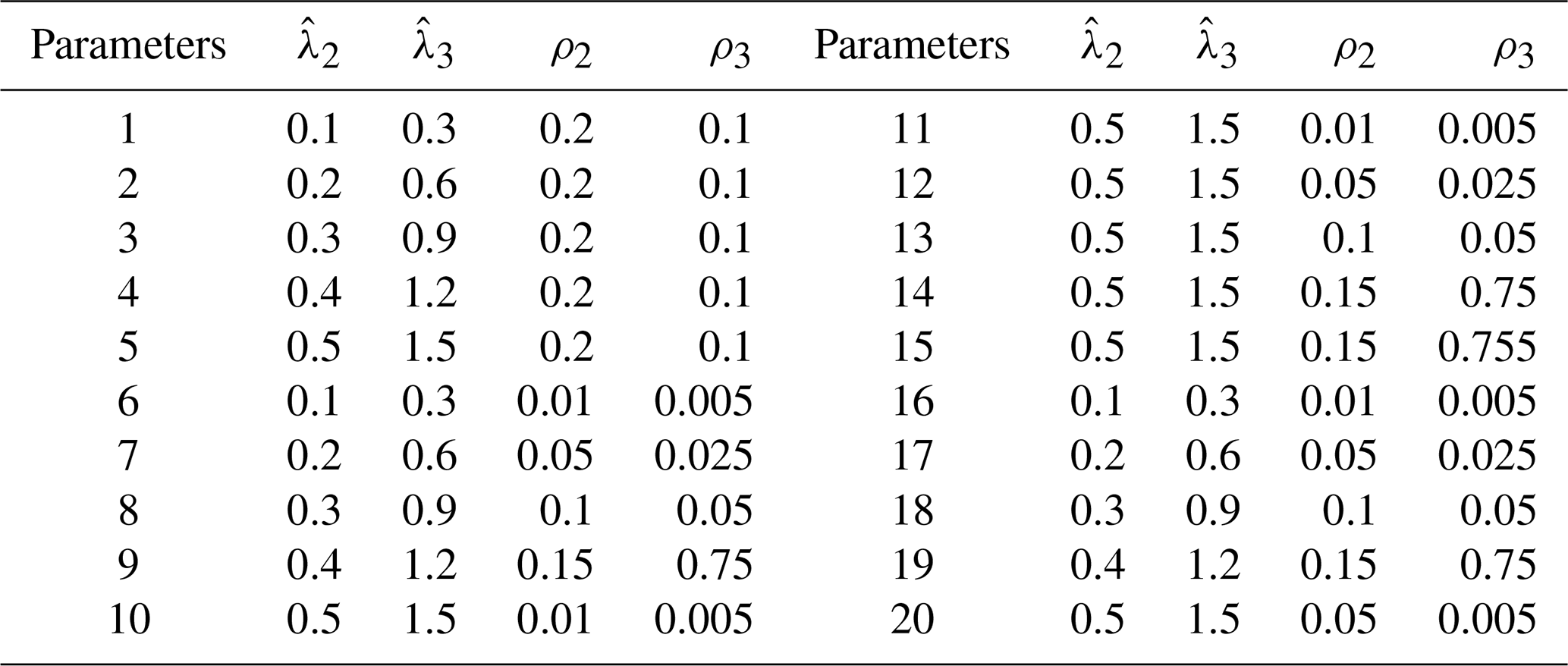
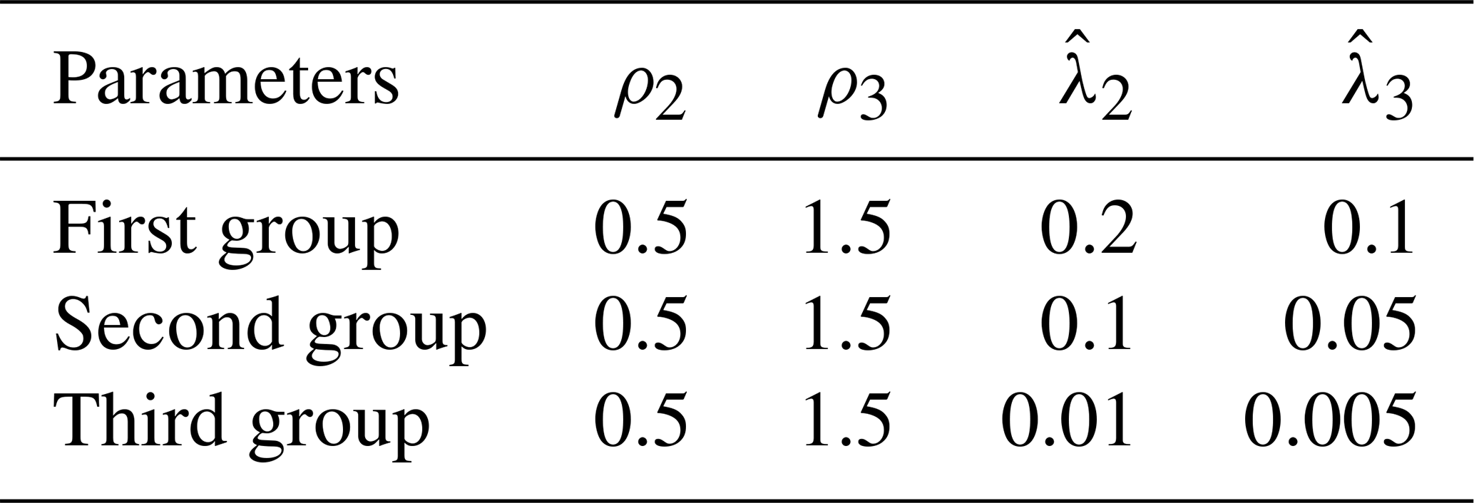
According to the value interval of the parameters, 20 groups of different control parameter points are selected as the parameter set which needs to be optimized. The ITSE is then used as the adaptability function of the algorithm, as shown in Table 1.
-
Calculating the adaptability function values of each parameter set updates the glowworm luciferin and completes the change phase of the renewal of fluorescein.
-
Updating the neighbors within the decision domain and the glowworm's movement location and completing the update phase of glowworm position.
-
Updating the adaptive step and dynamic decision domain range to complete the update phase of the dynamic perceptive range.
-
Deciding whether the algorithm meets the target according to the maximum number of iterations. If it is satisfied, then the optimal solution is achieved.

3.3 Simulation results and analysis
We use the above process to tune the parameter based on the IASGSO algorithm. The simulation in this paper was implemented in MATLAB, and the optimization trajectory of control parameters (, , ρ2, ρ3) are also shown in Fig. 3. As it can be seen, by increasing the number of iterations, each operation will produce a better solution. The obtained control parameters are improved after 200 iterations. Finally, the optimal solution of the controller parameters can be obtained as , , ρ2=0.2 and ρ3=0.1.
3.4 Performance test for step response
A step response performance test was used to verify the optimal degree of control parameters which concluded from the previous results. Here we change the value of the parameters according to the response curve of the system with different values of parameters. We then obtain the impact of variations in the controller parameter changes on the system response curve; hence, the influence of adjusting parameters on the control characteristics could be determined. The following are the results:
-
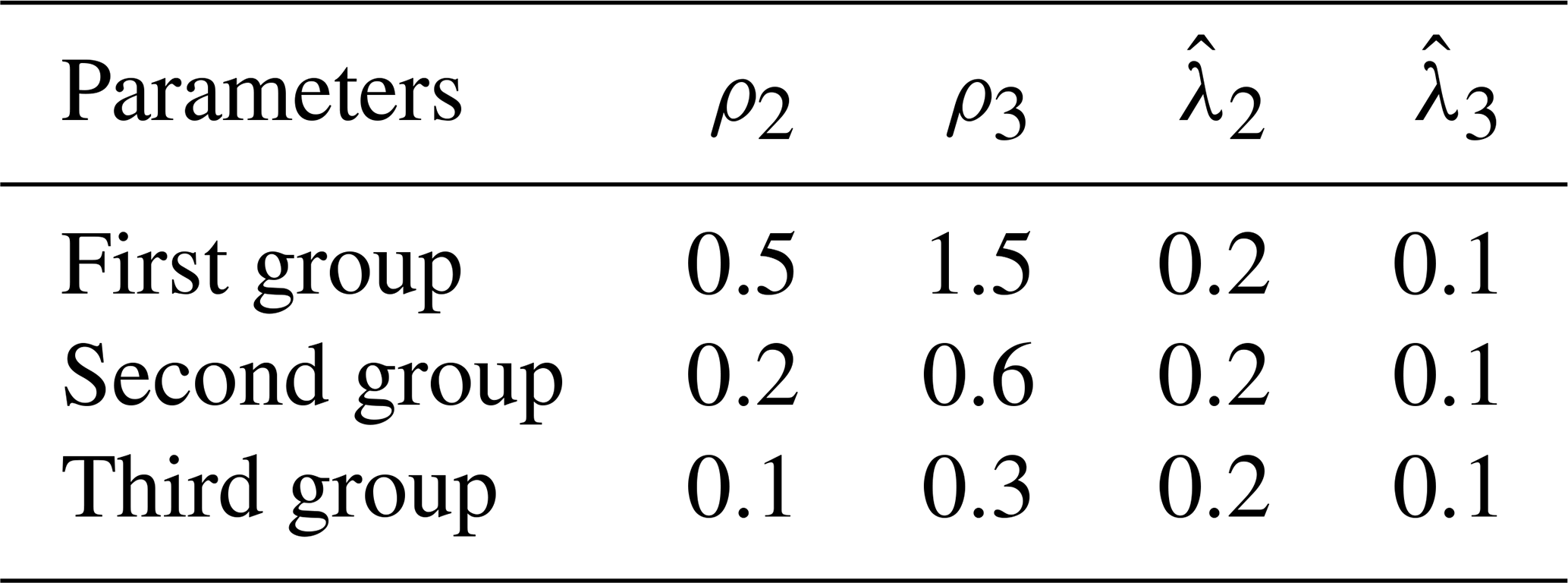
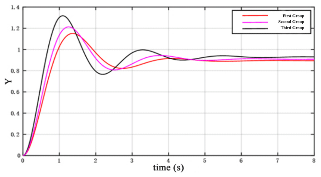
For constant values of ρ2 and ρ3, we obtain and . The corresponding values of each parameter in the system are shown in Table 2. The response curve is also shown in Fig. 4. As it is seen in Fig. 4, by reducing the value of and , the system response becomes faster, the overshoot (maximum deviation) and oscillation are increased and the stability of the system is reduced.
-
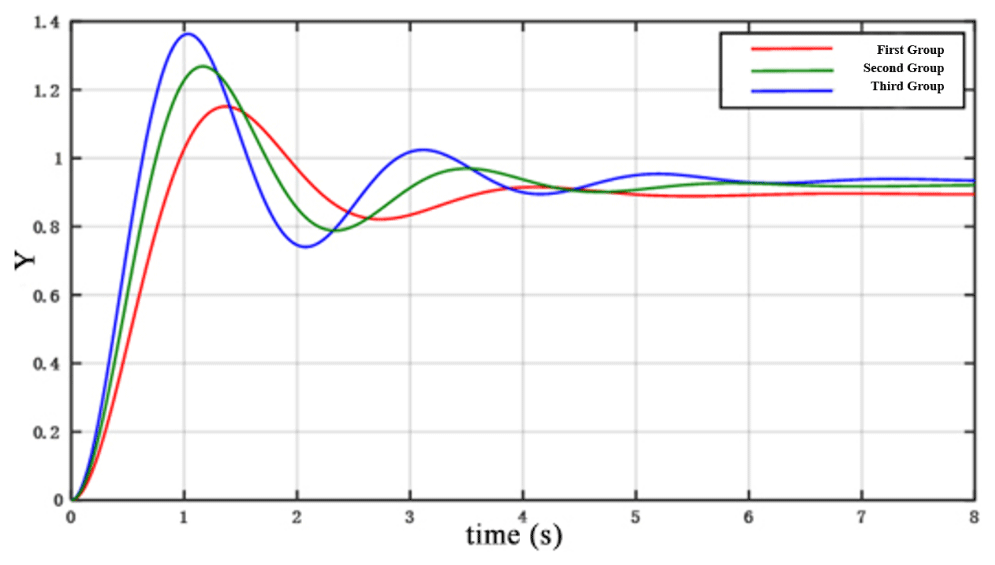
For constant values of and , we obtain ρ2 and ρ3. The corresponding values for each parameter in the system are presented in Table 3. The system response curve is further illustrated in Fig. 5. As seen in Fig. 5, by increasing the value of ρ2 and ρ3, the system response becomes slower, the overshoot amount (maximum deviation) is reduced, the oscillation is weakened and the stability of the system is improved.
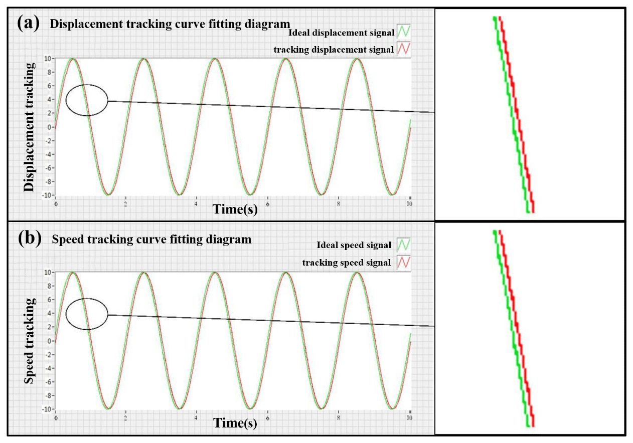
Figure 7Tracking curve-fitting diagram. (a) Displacement tracking curve-fitting diagram. (b) Speed tracking curve-fitting diagram.

As it is seen above, the following conclusions can be drawn: by increasing the values of and or ρ2 and ρ3, the tracking error ( becomes smaller, and the desired tracking accuracy is achieved. Ultimately, the optimal control parameters are , , ρ2=0.2 and ρ3=0.1.
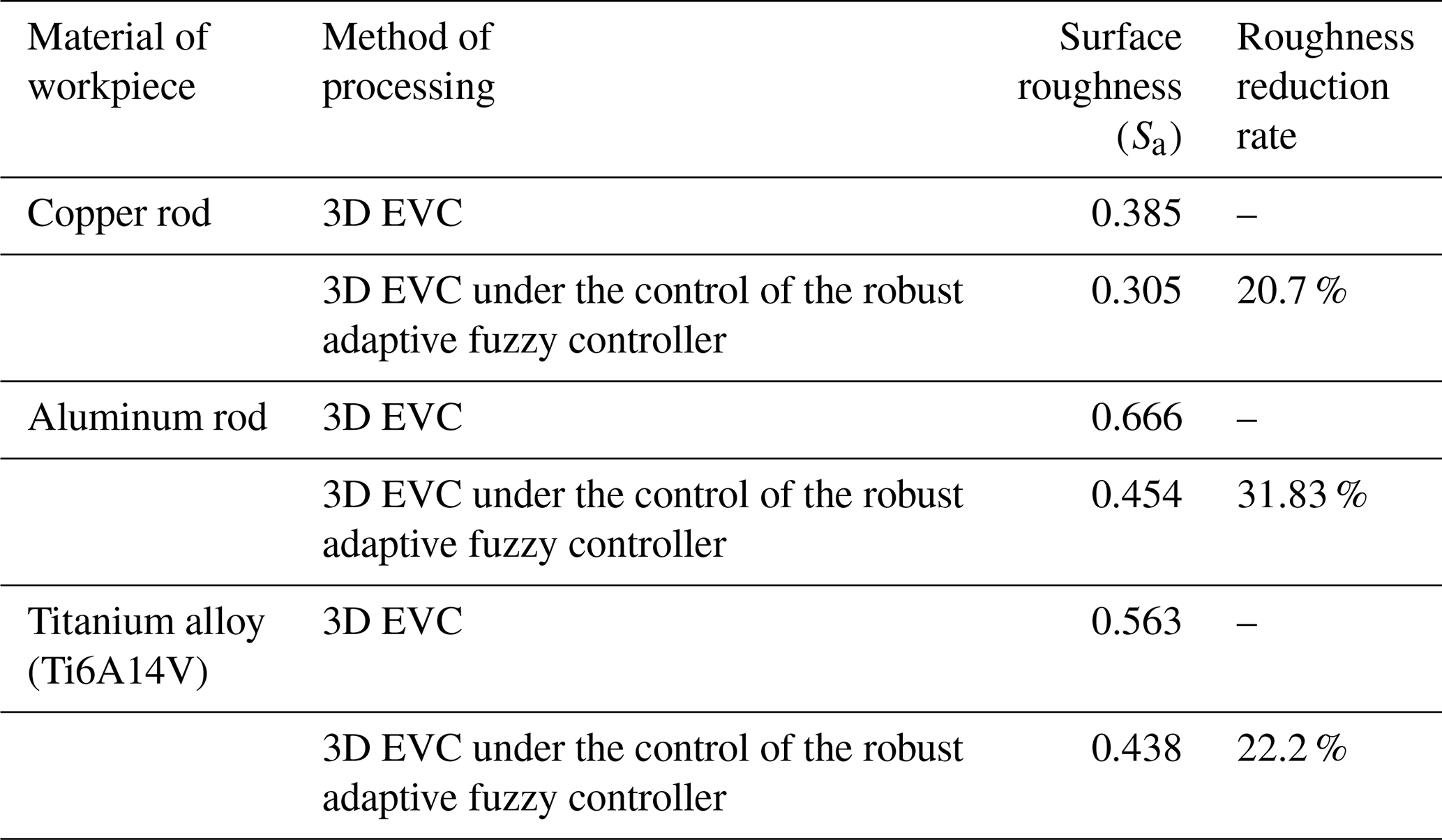
Table 4Surface roughness values for work parts under both machining methods.
4.1 Closed-loop test experiment for 3D EVC control system
4.1.1 Experimental setup
The 3D EVC closed-loop control system is shown in Fig. 6. The system comprises a 3D EVC device, an NI cRIO-9033 controller capacitive displacement sensor, a power amplifier and a Lenovo notebook computer. This section investigates the displacement tracking and velocity tracking of the sinusoidal signal of the 3D EVC device.
The robust adaptive fuzzy controller was programmed by LabVIEW software, and the NI cRIO-9033 controller was used to collect data. The display control of the LabVIEW front panel is used to process the collected data and output the fitting curve. The external interference in the experiment is also taken as d1(t)=sin (t); the initial value of the system variable was . The reference signal in the ideal state was yr(t)=sin (πt). The values of each parameter variable in the system are , , ρ2=0.2 and ρ3=0.1. The values are fed into the LabVIEW system design software program, and the data are collected by the NI cRIO-9033 controller. We then fit the collected sine function curve with the ideal standard sine function curve, and the experimental results are compared and analyzed.
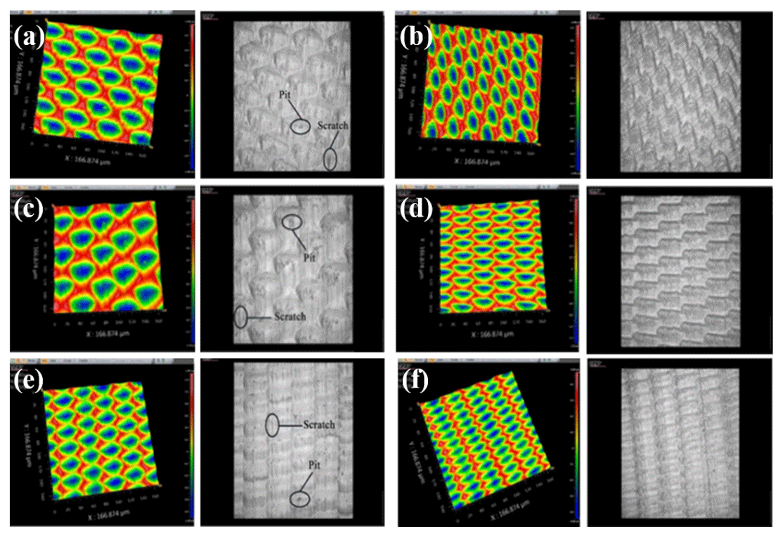
Figure 9(a, c, e) Surface morphology after 3D EVC processing for the (a) copper rod, (c) aluminum rod and (e) titanium alloy. (b, d, f) Surface topography after 3D EVC processing controlled by robust adaptive fuzzy controller for the (b) copper rod, (d) aluminum rod and (f) titanium alloy.
4.1.2 Test results and analysis
Running the program in the system design software LabVIEW and using and NI cRIO-9033 controller to transfer the collected data to the Wiener system model of the 3D EVC device, the displacement tracking curve-fitting diagram is obtained, as in Fig. 7a. The speed tracking curve-fitting diagram is also shown in Fig. 7b. As it is seen in Fig. 7, the results showed a good agreement between the ideal speed signal curve and the tracking speed signal curve. Similarly, the ideal speed signal curve is consistent with the tracking speed signal curve. Both displacement tracking curve and velocity tracking curve have a high fitting degree, which indicated that the robust adaptive fuzzy controller under the optimal parameters provides a better tracking effect.
4.2 Cutting experiments for 3D EVC devices
4.2.1 Experimental setup
The 3D EVC device-cutting experiment was conducted on the Nanoform 250 ultra-machine made by AMETEK (USA). The main instruments included the independently developed 3D EVC device, a NI cRIO-9033 controller, a C series analog input module NI 9222, a C series analog output module NI 9263, a DE-5300-013 displacement sensor, a power amplifier, a Nanoform 250 ultra-machine tool, a workstation and so on. The overall system of the cutting experiment can be seen in Fig. 8.
4.2.2 Surface profiling of cutting work-pieces
Here we examine the machining precision of 3D EVC under the controlling of the robust adaptive fuzzy controller with optimal parameters. A total of three workpieces with different materials (a copper rod, an aluminum rod and a titanium alloy, Ti6A14V) are considered for comparative verification experiments with two methods, including 3D EVC and 3D EVC under the control of robust adaptive fuzzy controller improved by IASGSO.
As shown in Fig. 9, the surface appearance of the copper rods, aluminum rods and titanium alloys (Ti6A14V) are compared under the control of 3D EVC and 3D EVC controlled by robust adaptive fuzzy controller, respectively.
The results of the surface roughness under two different cutting methods are shown in Table 4. As shown in Fig. 10 and Table 4, the copper rod, aluminum rod or titanium alloy (Ti6A14V) all indicate the comparative advantage in the surface roughness of 3D EVC processing under the control of robust adaptive fuzzy controller improved by IASGSO. The surface roughness value reduced to 20 %–32 %. Under the process of 3D EVC, obvious scratches and pits appeared on the surface morphology of the workpiece, but this phenomenon is avoided during the processing of 3D EVC under the control of the robust adaptive fuzzy controller improved by IASGSO. It confirms that the robust adaptive fuzzy controller under optimal participation has a comparative advantage in the processing accuracy of 3D EVC and, thus, verifies the validity of the optimal parameters of the controller.
To improve dynamic and static characteristics of the system and achieve an ideal control accuracy in the process, this paper tunes the parameters of the 3D EVC robust adaptive fuzzy controller and finds and verifies the optimal solution through simulation and experiment. Finally, the surface roughness was compared through cutting experiments, which proved the effectiveness and the following conclusions are formed:
-
The controller parameters were tuned by the IASGSO algorithm, and the optimal solution of controller parameters was obtained by MATLAB simulation. Analyzing the system response curve under different parameters under the step response performance test, it is known that increasing the value of , and ρ2, ρ3 can achieve the desired tracking accuracy, which verifies the optimality of the IASGSO algorithm for tuning the controller parameters.
-
The controller was applied to the 3D EVC device system model, and the displacement tracking signal, speed tracking signal and tracking error were analyzed through simulation. The control object had a little jitter at the beginning, but it could quickly stabilize and smoothly move towards the direction of the ideal displacement signal and the speed signal. This verifies the effectiveness of the optimal parameters of the controller and the robustness of the controller.
-
A closed-loop test experiment was performed on the 3D EVC control system, and the displacement tracking curve and the speed tracking curve were collected with the help of LabVIEW and the NI cRIO-9033 controller. The result showed that the ideal curve and the tracking signal curve were approximately coincident. This verifies the rationality of the parameter adjustment of the robust adaptive fuzzy device.
-
Under certain cutting conditions, copper rods, aluminum rods and titanium alloys were machined by 3D EVC and 3D EVC under the control of a robust adaptive fuzzy controller improved by IASGSO. The surface topography of the three sets of workpieces was then analyzed and compared. The surface roughness values were reduced by 20 %–32 %, which verifies the rationality of the controller parameter setting and the effectiveness of the control system.
No data sets were used in this article.
YSD conceptualized and visualized the project and wrote, reviewed and edited the paper with the help of MML. MML and JKZ did the investigation. JKZ also visualized the project and wrote the original draft with HW. The methodology, data curation and formal analysis was conducted by HW, while JQL supervised the project.
The authors declare that they have no conflict of interest.
The authors thank the reviewers for their valuable comments and Copernicus Publications for their copy-editing and typesetting services.
This research has been supported by the National Natural Science Foundation of China (grant no. U19A20104), Science and Technology Development Projects of Jilin Province (grant no. 20190201303JC) and Micro-Nano and Ultra-Precision Key Laboratory of Jilin Province (grant no. 20140622008JC).
This paper was edited by Jeong Hoon Ko and reviewed by Rui Huang and two anonymous referees.
Dong, G., Wang, L., Li, C., and Yu, Y.: Investigation on ultrasonic elliptical vibration boring of deep holes with large depth–diameter ratio for high-strength steel 18Cr2Ni4WA, Int. J. Adv. Manuf. Tech., 108, 1527–1539, https://doi.org/10.1007/s00170-020-05531-3, 2020.
Gandomi, A. H., Yang, X.-S., and Alavi, A. H.: Cuckoo search algorithm: a metaheuristic approach to solve structural optimization problems, Eng. Comput., 29, 17–35, https://doi.org/10.1007/s00366-011-0241-y, 2011.
García-Gutiérrez, G., Arcos-Aviles, D., Carrera, E. V., Guinjoan, F., Motoasca, E., Ayala, P., and Ibarra, A.: Fuzzy Logic Controller Parameter Optimization Using Metaheuristic Cuckoo Search Algorithm for a Magnetic Levitation System, Appl. Sci., 9, 2458, https://doi.org/10.3390/app9122458, 2019.
Jieqiong, L., Yingchun, L., and Xiaoqin, Z.: Tool path generation for fabricating optical freeform surfaces by non-resonant three-dimensional elliptical vibration cutting, P. I. Mech. Eng. C-J. Mec., 228, 1208–1222, https://doi.org/10.1177/0954406213502448, 2013.
Karakuzu C.: Parameter Tuning of Fuzzy Sliding Mode Controller Using Particle Swarm Optimization, International journal of innovative computing information and Control, 6, 4755–4770, 2010.
Kim, G. D. and Loh, B. G.: An ultrasonic elliptical vibration cutting device for micro V-groove machining: Kinematical analysis and micro V-groove machining characteristics, J. Mater. Process. Technol., 190, 181–188, https://doi.org/10.1016/j.jmatprotec.2007.02.047, 2007.
Kim, G. D. and Loh, B. G.: Characteristics of elliptical vibration cutting in micro-V grooving with variations in the elliptical cutting locus and excitation frequency, J. Micromech. Microeng., 18, 025002, https://doi.org/10.1088/0960-1317/18/2/025002, 2008.
Li, G., Xu, H., and Lin, Y.: Application of bat algorithm based time optimal control in multi-robots formation reconfiguration, J. Bion. Eng., 15, 126–138, https://doi.org/10.1007/s42235-017-0010-8, 2018.
Lin, J., Zhou, J., Lu, M., Wang, H., and Yi, A.: Design of Robust Adaptive Fuzzy Controller for a Class of Single-Input Single-Output (SISO) Uncertain Nonlinear Systems, Math. Problem. Eng., 2020, 1–11, https://doi.org/10.1155/2020/6178678, 2020.
Liu, C., Zhu, L., and Ni, C.: Chatter detection in milling process based on VMD and energy entropy, Mech. Syst. Signal Pr.g, 105, 169–182, https://doi.org/10.1016/j.ymssp.2017.11.046, 2018.
Lu, M., Zhou, J., Lin, J., Gu, Y., Han, J., and Zhao, D.: Study on Ti-6Al-4V Alloy Machining Applying the Non-Resonant Three-Dimensional Elliptical Vibration Cutting, Micromachines, 8, 306, https://doi.org/10.3390/mi8100306, 2017.
Lu, M., Wang, H., Lin, J., Yi, A., Gu, Y., and Zhao, D.: A nonlinear Wiener system identification based on improved adaptive step-size glowworm swarm optimization algorithm for three-dimensional elliptical vibration cutting, Int. J. Adv. Manuf. Tech., 103, 2865–2877, https://doi.org/10.1007/s00170-019-03743-w, 2019.
Ma, C., Shamoto, E., Moriwaki, T., and Wang, L.: Study of machining accuracy in ultrasonic elliptical vibration cutting, Int. J. Mach. Tools Manufact., 44, 1305–1310, https://doi.org/10.1016/j.ijmachtools.2004.04.014, 2004.
Nie, S.-K., Wang, Y.-J., Xiao, S., and Liu, Z.: An adaptive chaos particle swarm optimization for tuning parameters of PID controller, Optim. Contr. Appl. Met., 38, 1091–1102, https://doi.org/10.1002/oca.2314, 2017.
Ortiz, F., Simpson, J. R., Pignatiello, J. J., and Heredia-Langner, A.: A Genetic Algorithm Approach to Multiple-Response Optimization, J. Qual. Technol., 36, 432–450, https://doi.org/10.1080/00224065.2004.11980289, 2018.
Petkov, P.: Robustness of the analysis of Doppler-shift attenuation lifetime measurements according to the coincidence differential decay curve method with respect to class of uncertainties in the stopping powers, AIP Advances, 8, 075305, https://doi.org/10.1063/1.5026580, 2018.
Sheng, W., Shan, P., Mao, J., Zheng, Y., Chen, S., and Wang, Z.: An Adaptive Memetic Algorithm With Rank-Based Mutation for Artificial Neural Network Architecture Optimization, IEEE Access, 5, 18895–18908, https://doi.org/10.1109/access.2017.2752901, 2017.
Soma, S., Kaneko, O., and Fujii, T.: A new method of controller parameter tuning based on input-output data – Fictitious Reference Iterative Tuning (FRIT), IFAC Proceedings Volumes, 37, 789–794, https://doi.org/10.1016/s1474-6670(17)31566-5, 2004.
Tan, R., Zhao, X., Zou, X., and Sun, T.: A novel ultrasonic elliptical vibration cutting device based on a sandwiched and symmetrical structure, Int. J. Adv. Manuf. Tech., 97, 1397–1406, https://doi.org/10.1007/s00170-018-2015-9, 2018.
Verboven, P., Guillaume, P., and Cauberghe, B.: Multivariable frequency–response curve fitting with application to modal parameter estimation, Automatica, 41, 1773–1782, https://doi.org/10.1016/j.automatica.2005.03.023, 2005.
Xue, F., Cai, Y., Cao, Y., Cui, Z., and Li, F.: Optimal parameter settings for bat algorithm, Int. J. Bio-Insp. Comput., 7, 125–128, https://doi.org/10.1504/ijbic.2015.069304, 2015.
Yang, Y., Feng, G., and Ren, J.: A Combined Backstepping and Small-Gain Approach to Robust Adaptive Fuzzy Control for Strict-Feedback Nonlinear Systems, IEEE T. Syst. Man Cy. A, 34, 406–420, https://doi.org/10.1109/tsmca.2004.824870, 2004.
Yang, Y. M., Wang, X. P., Guo, L., and Fan, M.: Control Parameter Tuning of Magnetic Bearing PID Controller Based on Expansion Coefficient Critical Proportion, Appl. Mech. Mater., 150, 24–29, https://doi.org/10.4028/www.scientific.net/AMM.150.24, 2012.
Yildiz, A. R.: Cuckoo search algorithm for the selection of optimal machining parameters in milling operations, Int. J. Adv. Manuf. Tech., 64, 55–61, https://doi.org/10.1007/s00170-012-4013-7, 2012.
Zhang, C. and Song, Y.: A novel design method for 3D elliptical vibration-assisted cutting mechanism, Mech. Mach. Theory, 134, 308–322, https://doi.org/10.1016/j.mechmachtheory.2019.01.007, 2019.
Zhu, L. and Liu, C.: Recent progress of chatter prediction, detection and suppression in milling, Mech. Syst. Signal Pr., 143, 106840, https://doi.org/10.1016/j.ymssp.2020.106840, 2020.