the Creative Commons Attribution 4.0 License.
the Creative Commons Attribution 4.0 License.
 | 14 Apr 2021
Design and performance analysis of wave linear generator with parallel mechanism
Yulong Wang
Zhihua Wang
Can Qin
Considering the irregularity of wave motion, a wave energy converter (WEC) based on 6-UCU parallel mechanism has been investigated. A buoy connected to moving platform is used to harvest wave energy. Each chain is equipped with the linear generator of the same structure, which can convert the absorbed wave energy into electrical energy. Based on the inverse kinematics analysis of parallel mechanism, the position of the parallel mechanism is solved by using the space closed-loop vector method; the relative motion of stator and translator is obtained. Through electromagnetic numerical simulations, the influences of linear generator parameters such as magnetization mode, air gap, and yoke shape on electromagnetic performance were evaluated. Numerical results show axial magnetization and Halbach magnet array can increase magnetic flux intensity more than radial mode. Furthermore, the rule of electromagnetic resistance is discussed with the change of the speed amplitude and the angle frequency. For a case, dynamic differential equation of the whole system is established. The conversion rate of wave energy is derived.
- Article
(7626 KB) - Full-text XML
- BibTeX
- EndNote


With the gradual depletion of fossil fuels, developing renewable energy has received worldwide concern. Ocean wave energy (OWE) is regarded as a promising source of energy (Clément et al., 2002). The potential energy that can be extracted from ocean waves is about 2000 TWh yr−1 (Ghasemi et al., 2017), which is the same order of magnitude as the current world's annual power consumption (Drew et al., 2009). The conversion and utilization of wave energy is an effective way to reduce dependence on fossil fuels.
Wave power generation is a main form of wave energy utilization, which is mainly realized by wave energy converter (WEC). The energy harvesting system and the converter system are the two main parts of WEC. The structure of energy harvesting includes the oscillating float, the oscillating water column, and pendulum; most of them are mainly used to absorb wave energy in the heave direction. Waves have a variety of scales: seasonal, daily, or even hourly. WEC based on parallel mechanism is suitable for harvesting. At present, parallel mechanism has been successfully used in various industrial fields such as the delta parallel robot (Dastjerdi et al., 2020) and Gough–Stewart parallel manipulators (MGSPMs) (Gexue et al., 2004; Katsushi et al., 2004; Tong et al., 2020). Parallel manipulators are closed-loop mechanisms presenting very good potential in terms of accuracy, rigidity, and ability to manipulate large loads. These structures are rarely used in wave energy conversion devices.
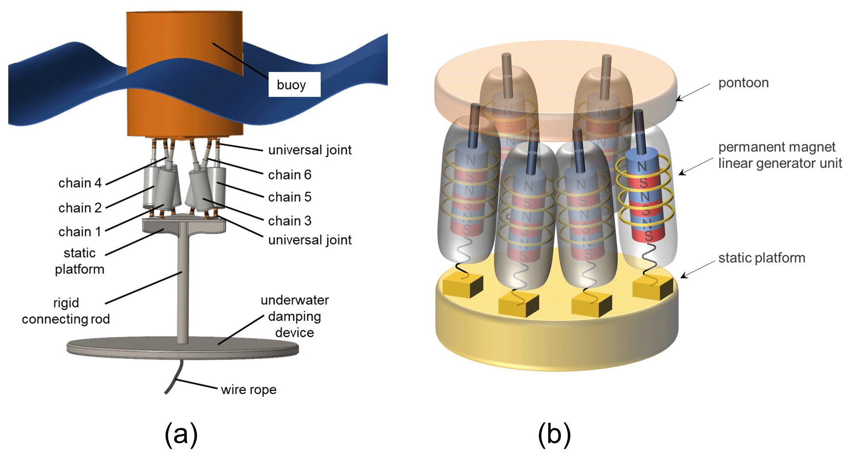
Figure 1The wave energy converter based on 6-DOF parallel mechanism. (a) The whole device. (b) Power generation schematic diagram of the mechanism.
In this context, the power take-off (PTO) system based on 6-UCU parallel mechanism is adopted to realize wave energy conversion, and the parallel mechanism is used to realize the collection of multi-directional wave energy. The linear generators located on brain chains are directly used to convert the captured wave energy into electrical energy. In order to optimize the structure of linear generators and improve the conversion rate of wave energy, electromagnetic simulation analysis was conducted to estimate the performance of linear generators with different structural parameters.
Application of linear generator in WEC
The energy converter system is usually a hydraulic or direct drive. A direct drive linear generator has been found to be attractive compared to other generators, which can directly convert the wave energy into electrical energy; the energy loss of the intermediate conversion link is reduced (Zhang et al., 2019). Due to their utilization of the direct-drive linear motion system, a linear point absorber wave energy harvesting device was developed in the Lysekil project at Uppsala University, Sweden; the power system used in the linear generator unit is specified with clear requirements (Temiz et al., 2018; Leijon et al., 2008). A linear primary permanent magnet is described in Du et al. (2013), which is proposed for direct drive OWE conversion.
Most papers focus on the improvement of the electrical power generation from OWE in various ways. The optimal electrical energy extraction from wave energy is investigated using a dual coaxial-cylinder system, which operates with a permanent magnet linear generator (Son et al., 2016). A new dual-port linear electrical generator (DPLEG) is capable of transferring electrical power to an adequate voltage even at zero vertical velocity of the oceanic wave (Farrok et al., 2020). An encouraging way to convert OWE into electricity is to use a linear, synchronous, longitudinal flux permanent magnet motor, in which the piston is driven by a buoy (Ekergård et al., 2020). A lightweight translator has been proposed in Farrok et al. (2017) to improve the dynamics of the linear generator. Another primary permanent linear generator (PMLG) has been proposed in Keysan et al. (2012) to minimize the overall system mass. It has been reported (Prudell et al., 2010; Farrok et al., 2018; Zhu et al., 2015) that a PMLG with a saltwater air gap between the buoy components is a feasible method to avoid irreversible magnetization. A high-power density linear generator is proposed in Farrok and Islam (2018), where the armature windings are placed in the translator. A segmented permanent-magnet linear generator structure was presented, which expands wave energy capture frequency bandwidth (Qiu and Wang, 2019).
2.1 Mechanism principle
The designed 6-DOF (degrees of freedom) wave energy converter can absorb wave energy from different directions at the same time. The structure is shown in Fig. 1a. The device is mainly composed of a buoy fixed to the moving platform which is used to harvest wave energy; six linear generators (PTO device) are attached t six parallel chains, and a base platform is fixed to the seabed with anchor chains, where both platforms are connected by 6-UCU chains. Each linear power generation branch connects the moving platform and the fixed base with universal joints or spherical joints at both ends. The working principle of the device is as follows: under the action of wave exciting force, the periodic motion of the buoy makes the translator and the stator produce the relative movement so that the magnetic flux in the stator coil changes constantly, and the induced electromotive force is generated. The external energy storage devices are connected to form a closed-loop system for generating electricity and storing energy. The power generation schematic diagram of the mechanism is shown in Fig. 1b.
2.2 Inverse kinematics
The designed WEC is based on 6-DOF parallel mechanism. As is seen in Fig. 2, a fixed Cartesian frame O–xyz is located at the center of the base platform, and a movable frame of reference O′– is located at the moving platform. To simplify the model, the universal joint is regarded as a point. The base platform is hosted at co-located points [], and the moving platform is hosted at points []. The two universal joints close to each other form a group and are placed at an angle of 120∘ on a circle formed by connecting points on the moving and base platforms. The two connections of the universal joint points of the moving and base platform are regarded as six independent vectors, which can be expressed as and A6B5.
For the given position and attitude of the moving platform, the coordinates of the total universal joints of the moving and base platform related to the fixed Cartesian frame can be obtained, and the length and direction of every branch chain can be derived by the inverse solution model of the parallel mechanism.
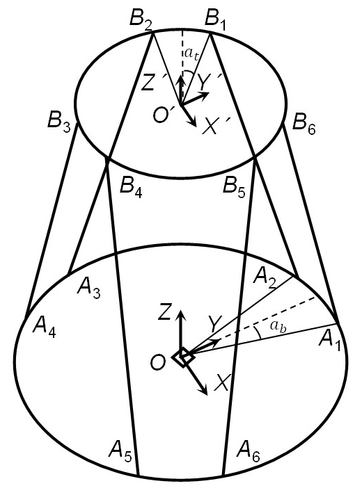
Axis Oy is perpendicular to A1A2, and axis is perpendicular to B1B2. mb and pb are the distribute angle of the joints on the base relative to Ox, and mt and pt represent the distribute angle of the joints on the moving platform relative to , which is expressed as follows:
where , and αb and αt are half of angle A1OA2 and .
where z is the initial distance between the moving platform and the fixed platform. rt is the radius of the moving platform, and rb is radius of the base platform. |lj| is defined as a chain vector, . The calculation process can be realized by writing a script in MATLAB. Any vector in the moving coordinate system can be transformed to a representation relative to the static coordinate system.
A generalized coordinate vector which describes the position and orientation of a 6-DOF parallel mechanism is defined as . denotes the translation vector of the movable frame O′– with respect to the fixed frame O–xyz. defines the orientation of the frame O′– with respect to the fixed frame O–xyz.
where T is the rotation matrix. α, β, and γ are roll angle, pitch angle, and yaw angle, respectively. The coordinate values of six universal joints in the respective coordinate system of the moving and base platforms can be calculated.
Six universal joints are divided into two groups according to 120∘ distribution, which are expressed with two matrices of Aj and Bj (). Both are a 6×3 matrix, and each row represents the coordinate values of the corresponding universal connection points.
The length of each chain is
The length change of each branch chain is obtained from Eqs. (5) and (9):
2.3 Inverse kinematics solution example
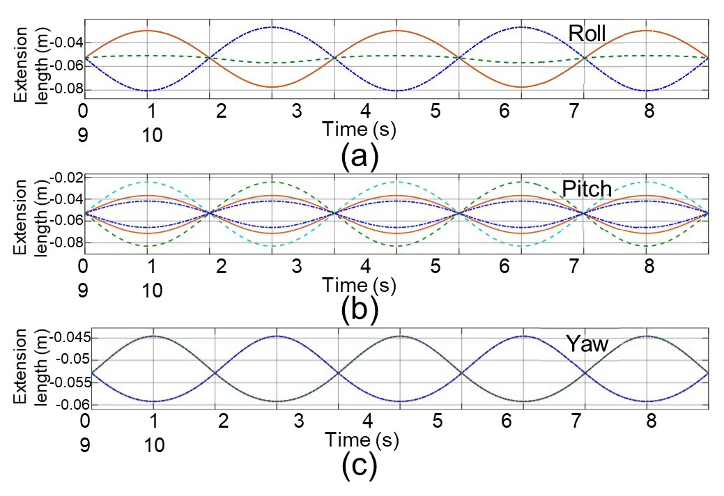
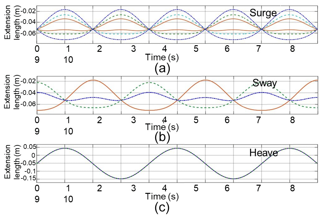
The extension of each branch can be obtained by subtracting the original length of each chain calculated. For a case here, when angle αb and αt are 15∘, rb is equal to 2.8 m, rt is equal to 1.8 m, and z is 0.63 m. Wave shaking amplitude is ; the extension length of each chain under a single motion state is shown as Fig. 3. When wave amplitude is 0.1 m, extension length of each branch chain under a single motion state is shown as Fig. 4.
3.1 Dynamic differential equation
The whole device has complex dynamic characteristics under the action of wave forces. The differential equation of motion can be written as (Cargo et al., 2016)
where m is the mass matrix of the buoy and moving platform. is the motion acceleration matrix of the buoy. x is the displacement matrix of the buoy. Fw is the wave excitation force of the buoy. Fc is the electromagnetic damping force, which can be obtained from the electromagnetic simulation analysis. Fr is given by the hydrostatic restoring force. Fs is the spring force on chains.
3.2 Wave excitation force
Generally, actual wave motion is irregular. The irregular wave will inevitably make the device move in 6 DOF, as shown in Fig. 5, which can make full use of the multi-degree-of-freedom characteristic of the device to absorb multi-directional wave energy.
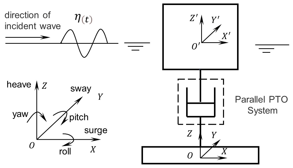
Only the motion law of the device under the action of micro-amplitude wave is discussed. In order to describe it in mathematical language, it can be idealized as the wave surface equation of sinusoidal motion or cosine motion at a certain frequency:
where H is the wave height, k is the wave number, and ω is the wave angular frequency. kx−ωt represents the phase of the wave.
The potential energy of incident wave satisfies Laplace's equation and corresponding boundary conditions in the whole wave field. According to the linear wave theory, the velocity potential ϕ of incident wave can be expressed as (Bharath et al., 2018)
where d is depth of water. z is the location of water particle. The wave surface equation makes every wave particle have periodicity in time and space, which can simplify the calculation process of the wave exciting force. The wave energy conversion device used in this article will be a large-scale structure (, D is the diameter of the buoy, L is the wave wavelength, ). The structure has a great influence on the wave field, and it is assumed that seawater is an ideal fluid that is uniform, inviscid, and incompressible. The viscous force on the structure is small, but the inertial force is dominant. The Froude–Krylov theory can be used to calculate the excitation force of the wave on the device (Tarrant and Meskell, 2016). In this model, the wave excitation force is corrected by calculating the integral of the undisturbed incident wave pressure on the surface of the structure and then multiplying it by the diffraction coefficient representing the additional mass effect and diffraction effect.
n is the outer normal vector of a point on the surface of the structure, and c is the diffraction coefficient. FF–K is the Froude–Krylov force generated by the undisturbed incident wave pressure on the structure.
If velocity potential ϕ is substituted into the linearized Bernoulli equation, the wave pressure distribution p on the surface of structure can be obtained:
The wave pressure of an undisturbed incident wave can be expressed:
4.1 Structure design
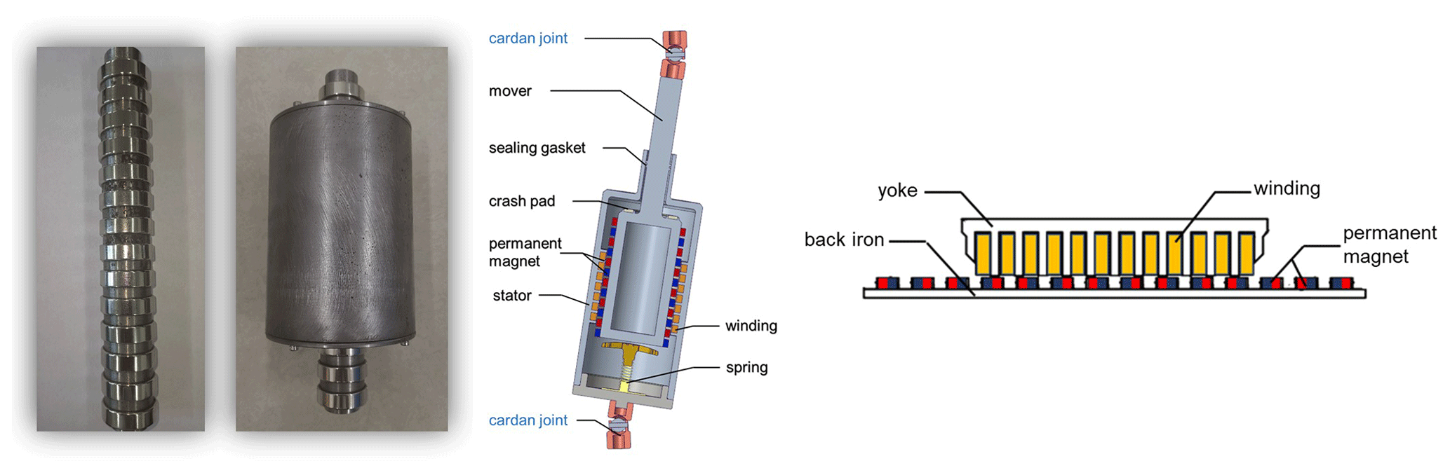
A cylindrical linear generator has a high utilization rate of action area, compact structure, and small influence of radial force, which is selected as the power-generating chain of the parallel mechanism. The translator of the generator includes a permanent magnet, back iron, and magnetic conductor. NdFe35 is selected as permanent magnet material, which has fairly good magnetization and is easy to manufacture. The neodymium iron boron permanent magnets are used in the translator with a remanence magnetic flux density of 1.1 T and a coercive force of −837 000 A m−1 (Farrok et al., 2020). The back iron and magnetic block of the translator are made of annealed low-carbon steel with high permeability.
The nonlinear magnetic properties of the material are simulated by interpolation function of the B–H curve. The stator of the generator consists of an iron core and a wound coil. Copper with good conductivity is used as wound coil material. Combined with the mode of distributed wound and pole-shoe type stator yoke, the magnetic field is limited in the winding circuit, which can reduce the magnetic leakage, generate the highest induction voltage as far as possible, and improve the conversion rate of energy. The branch chain prototype and linear generator internal structure are as shown in Fig. 6.
In practical engineering, the air gap of the generator is of great significance to the work of the translator. Too small of an air gap will cause friction between translator and stator, and it will affect the service life and work stability. Too large of an air gap will reduce productivity. In order to ensure the normal operation of the generator, the thickness of air gap is set as 1 mm.
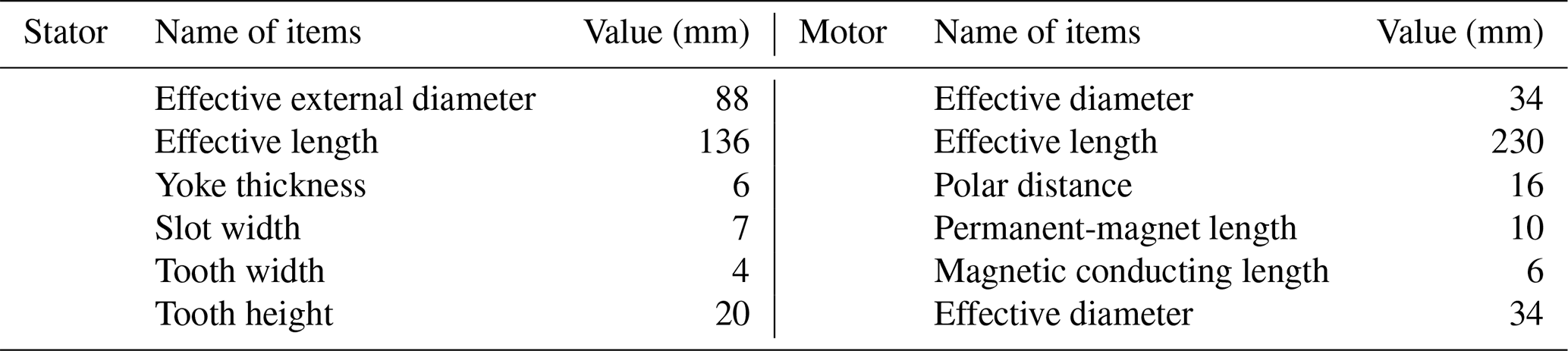
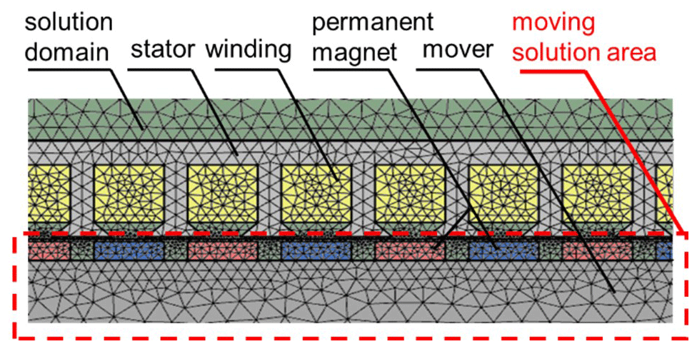
4.2 Electromagnetic simulation
A 2D mesh model is generated by using MAXWELL as shown in Fig. 7. The geometrical parameters of each part were defined in Table 1. The mesh quality of the discrete structure has a direct impact on the solution time and the accuracy of the results in analysis with the FEM (finite-element method). Therefore, a subdivision method, which is based on the edge length of the element on the surface, is used to mesh the area. The maximum values of the triangle edge length of the selected region are given respectively. The mesh size satisfies the following conditions: the solution domain>stator, motor iron core>permanent-magnet>stator winding>moving solution area. The density of the mesh in the moving solution area is smaller, and the solution accuracy is increased (Nader et al., 2012). By using the solver MAXWELL, the analysis result with different structure parameters can be obtained.
4.3 Influence of magnetization mode
There are three magnetization methods: radial magnetization, axial magnetization, and Halbach array magnetization. Figure 8 shows the magnetic flux lines A and flux density B under the structure of three magnetization modes.
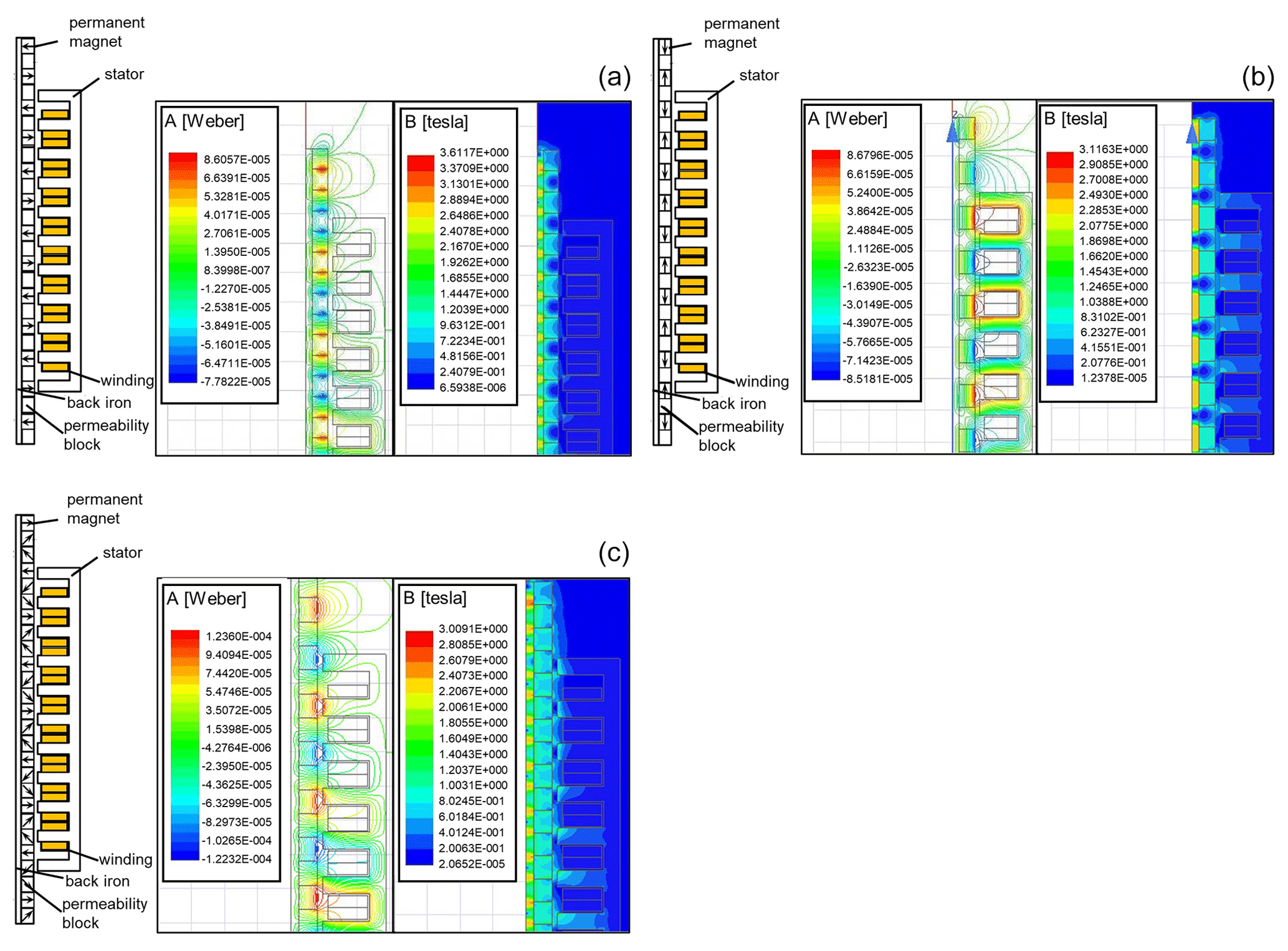
Figure 8Magnetic flux lines and flux density: (a) radial magnetization, (b) axil magnetization, and (c) Halbach magnetization.
In order to compare the magnetic flux density of the three magnetization methods at air gap, cogging gap, and radial direction, three auxiliary lines a, b, and c are referred to as shown in Fig. 9a. Line a represents the air gap, and line b denotes the cogging gap in the end of the yoke. Both a and b are parallel to the axis, while line c is along the radial direction.
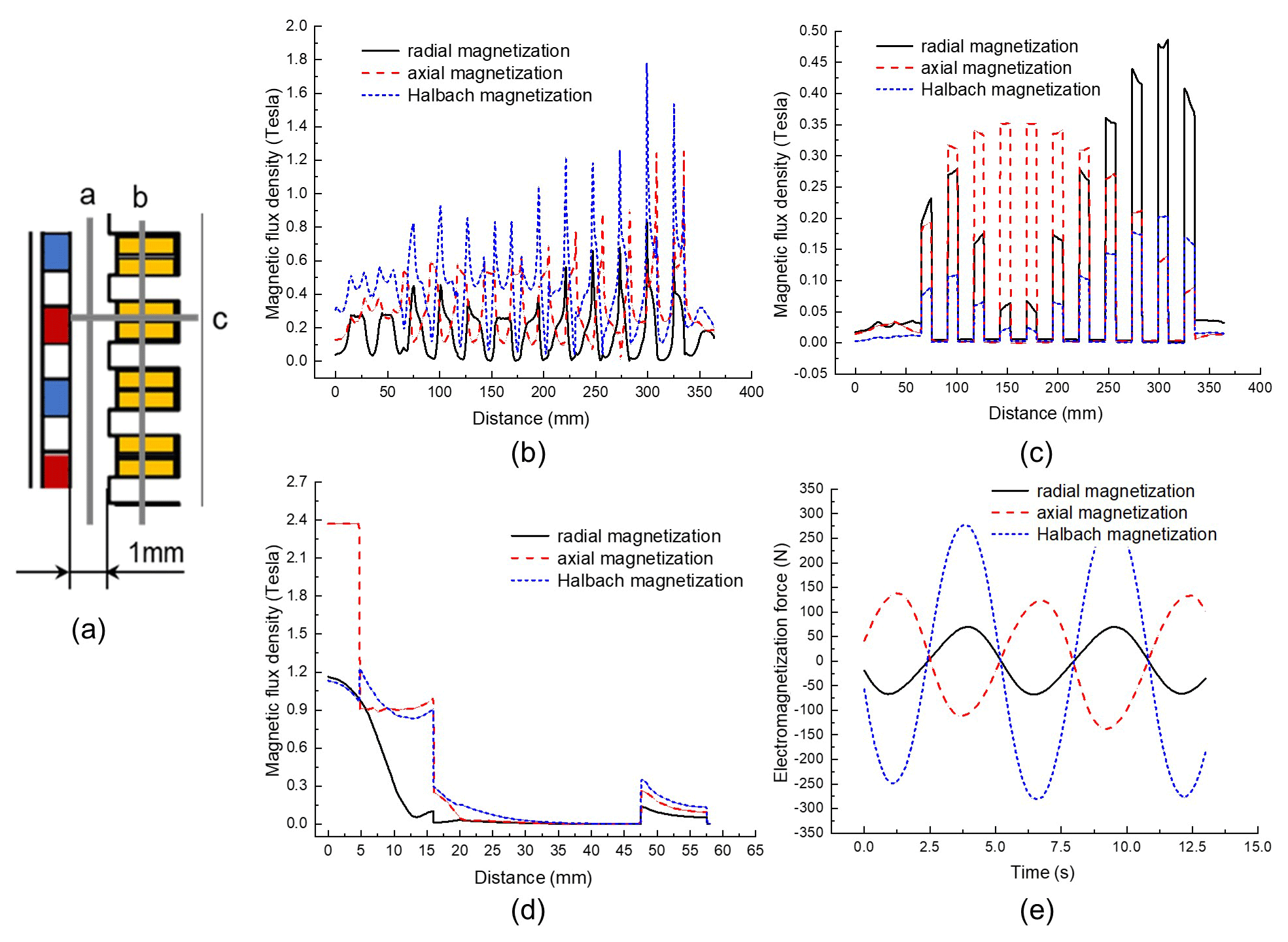
Figure 9(a) Auxiliary lines from different directions, (b) magnetic flux density at different positions of air gap (line a), (c) magnetic flux density at different positions of tooth tip (line b), (d) flux density in the height direction of yoke (line c), and (e) magnetization force of each magnetizing mode.
As can be seen from Fig. 9b, the magnetic flux density varies with the axial position under different magnetization modes along marking line a, which is related to the relative position of the magnet and stator teeth. The magnetic flux leakage phenomenon and uneven radial force of the whole static magnetic field occurred as usual. Relevant studies show that these problems can be alleviated by optimizing the pole slot ratio and the shape of the yoke. Figure 9c illustrates the magnetic flux density of various magnetization modes at the stator teeth along marking line b, which can help the design to obtain greater no-load voltage. Figure 9d displays the radial magnetic induction values of three different magnetization methods along marking line c. Figure 9e shows the variation of electromagnetic force of three different magnetization modes with the relative motion time of the moving stator.
According to the current finite-element analysis, the following conclusions can be drawn.
-
It is worth noting that the magnetic flux density of Halbach magnetization mode is larger than that of the other two magnetization methods.
-
In the nephogram of radial magnetization mode, it can be observed that a “U” shape is formed on the side near the yoke of each permanent magnet, which indicates that the magnetic field strength of the center of the permanent magnet is slightly lower than that of the two sides.
-
According to the cloud chart of axial magnetization mode, the magnetic flux density of back iron under axial magnetization mode is higher than that of the other two modes, which means that the axial magnetization mode requires a thicker back iron.
-
The results show that, in radial direction, the flux density of axial magnetization is the largest near the rotor permanent magnet, and the maximum value is 2.36 T.
Based on the comparison, it can be preliminarily determined that Halbach magnetization mode should be selected when centralized winding is used, and axial magnetization mode should be selected when using distributed winding. In this paper, considering the simplicity of winding and the influence of cogging force on stator, the axial magnetization mode and winding mode of distributed winding are finally selected.
4.4 Influence of permeability block
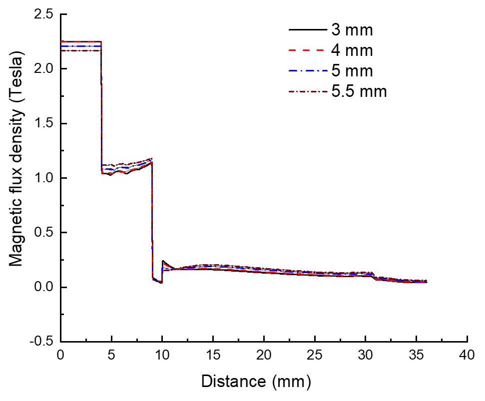
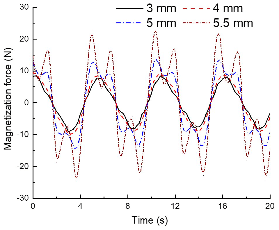
For the linear generator with designed axial magnetization mode, when the shape and size of the permanent magnet are determined, the height of the permeability block has an important influence on the magnetic flux density and the electromagnetic force. Simulation analysis was carried out for the permeability block with the thickness of 3, 4, 5, and 5.5 mm. The thickness of the magnetic block has little effect on the magnetic flux density in the radial direction of the axial magnetization mode as shown in Fig. 10. Figure 11 shows that the electromagnetic force of the linear generator increases significantly with the increase of the thickness of the magnet block.
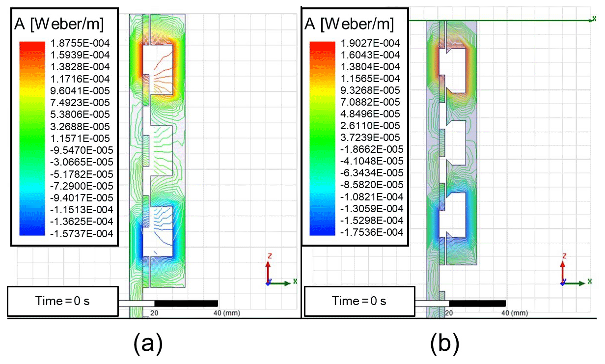
4.5 Influence of yoke shape
This section discusses the effect of yoke shape on power generation efficiency. The yoke mechanism generally adopts E type and pole-shoe type. The distribution magnetic flux density of the two shapes is shown in Fig. 12a and b. It can be seen that when two magnets are close to the opposite yoke, the linear density of the magnetic field will increase sharply, while the magnetic line of force produced by the magnet separated from the yoke will be sparse, and the density and staggered changes will produce strong electromagnetic induction in the coil. The results show that the pole shoe yoke can effectively improve the magnetic flux intensity, make the distribution of magnetic induction lines more reasonable, make more magnetic flux lines pass through the yoke, and reduce magnetic leakage.
4.6 Influence of motion parameters
As in the above analysis, the moving platform is affected by wave force and transmits the force to the moving part of the linear generator. Therefore, the relevant motion of stator and translator can be derived from the motion of moving platform, and the motion speed of the translator can be analyzed briefly.
The simple equation for the velocity of the translator is as follows:
where A is velocity amplitude, and ω is angular frequency.
By using the control variable method, the influence of velocity amplitude and angular frequency on the electromagnetic force is studied. The angular frequency is assumed to be 0.1π, and the maximum displacement of the translator is 90 mm. Then the amplitude of the motion velocity is 4.5π. The range of angular frequency is 0.1π to π with an interval of 0.1π. The result is shown in Fig. 13.
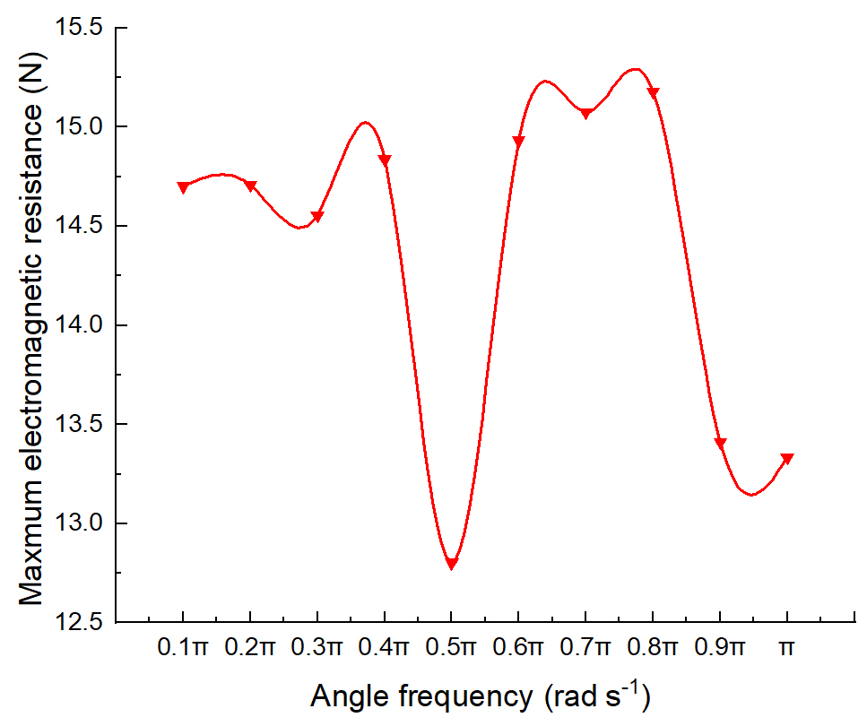
Figure 13Influence of different angular frequencies on the maximum value of electromagnetic resistance.
Then, keeping the angular frequency 0.5π unchanged, the electromagnetic force of the translator is measured when the velocity amplitude changes from 2.5π to 4.5π every 0.5π, and the results are shown in Fig. 14. The electromagnetic force obtained in the electromagnetic simulation can be used as the damping term in the differential equation of motion.
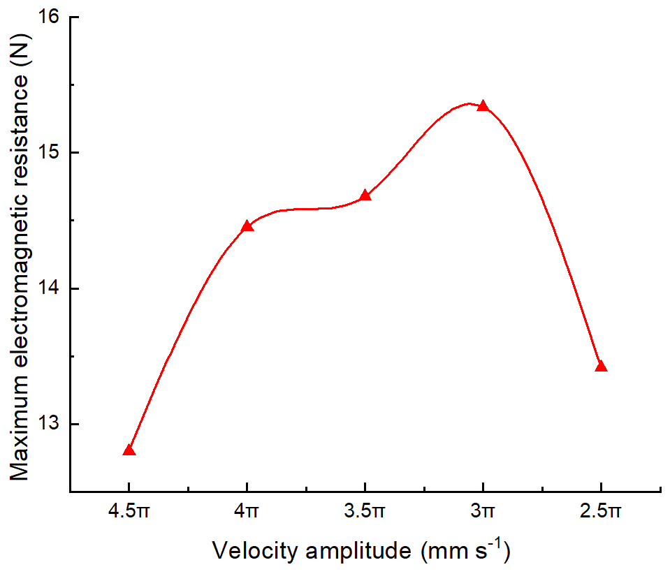
Figure 14Influence of different velocity amplitudes on the maximum value of electromagnetic resistance.
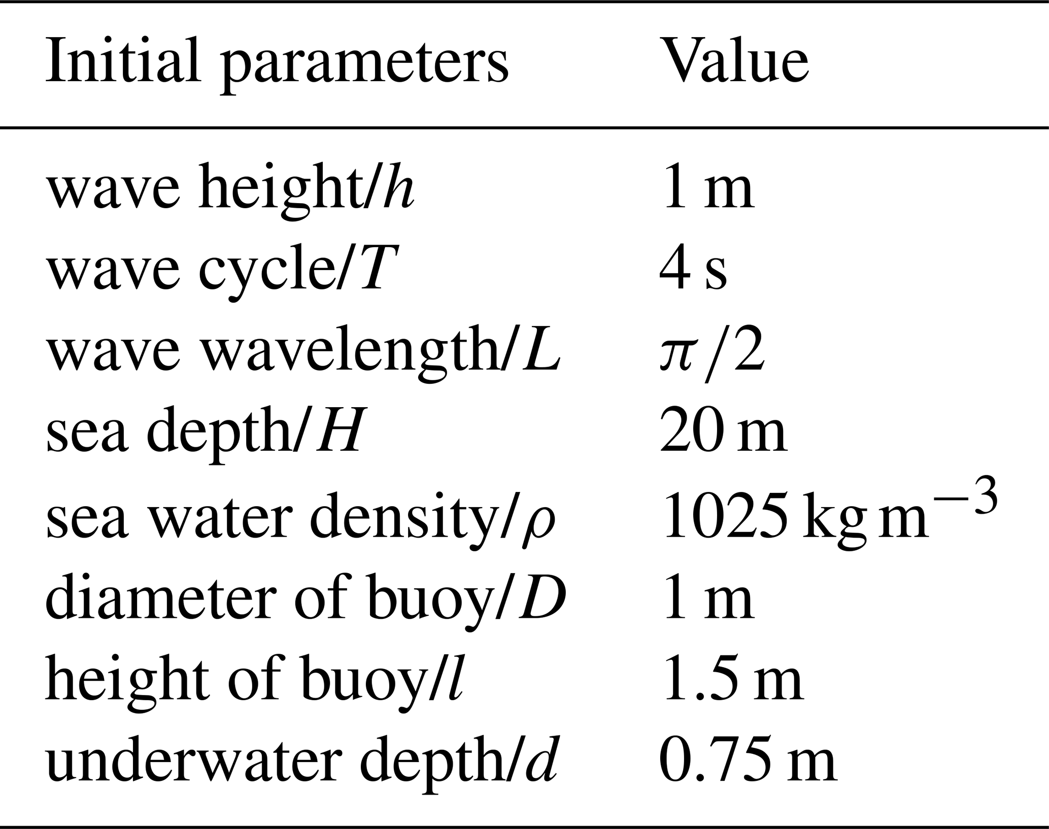
Wave parameters and buoy size are as shown in Table 2. For a given wave height, sea depth, and wave period, the motion law of each power generation chain of the device can be derived according to the dynamic differential equations obtained in Sect. 3.1.
In this paper, only heave motion is considered. And the power generation performance of the device will be explained from this unilateral aspect. As can be seen from Fig. 4f, the six branch chains of the device have the same motion law, which simplifies the analysis model.
Among them, according to the F–K (Froude–Krylov theory) method, the wave excitation force of the buoy is
As shown in Fig. 15, the undulating motion of the linear generator increases in proportion with the increase of wave height, and the motion frequency is consistent with the wave motion frequency in Fig. 16.
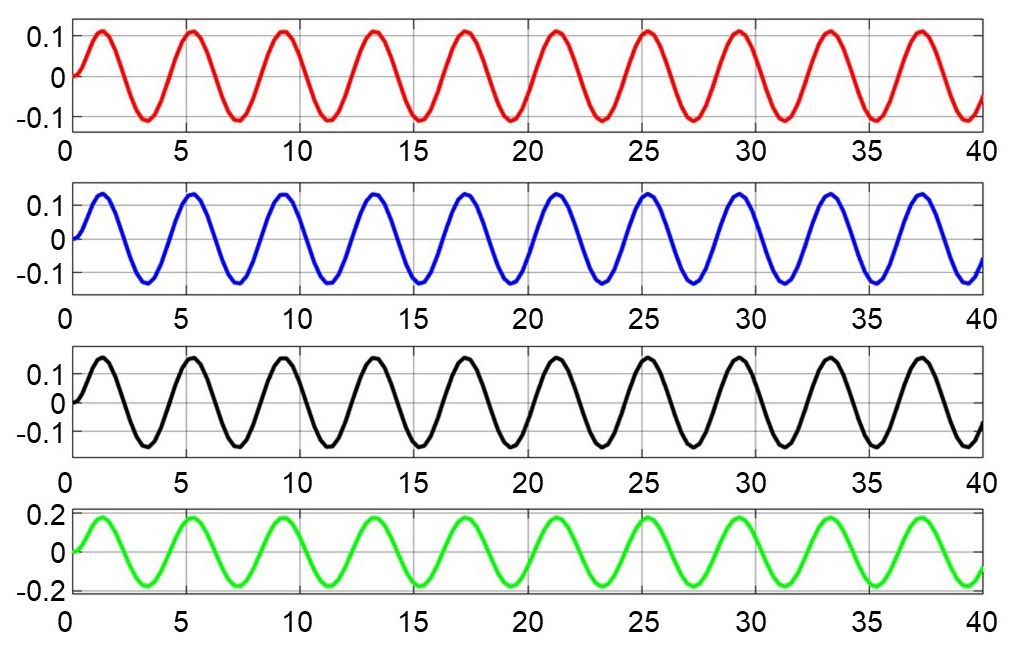
Figure 15Movement law of the buoy at different wave heights. (The wave heights from top to bottom are 1, 1.2, 1.4 and 1.8 m.)
If the influence of friction is not considered, the voltage of the generator is proportional to the moving speed of the translator. The electric energy produced by the generator is equal to the work done by the electromagnetic force (Castellucci et al., 2017). That is, the electromagnetic damping force provides mechanical positive power generation, which can be calculated by the following equation:
where B is the magnetic field strength, I is the current intensity in the circuit, Lw is the winding length of the cutting magnetic induction line, and is the relative motion speed of the translator and stator. The electromagnetic force F=BILw is analyzed according to electromagnetic simulation. The generating energy of the device can be obtained in one wave period.
Based on the linear wave theory, the vibration frequency of each wave particle is equal (De O Falcão, 2010; Astariz and Iglesias, 2015). In the wavelength range, the wave input energy can be calculated by selecting a wave motion period:
According to Eqs. (20)–(22), the wave energy conversion rate of the wave linear generator in the heave direction is estimated to be 20 %.
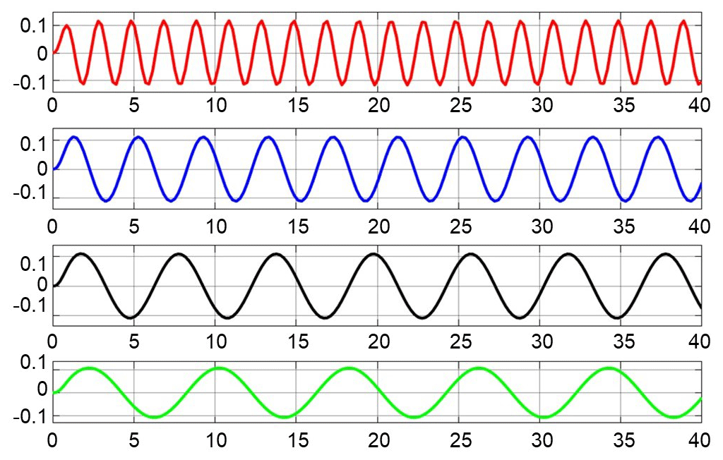
Figure 16Influence of wave period on the position of the float. (The wave periods from top to bottom are 2, 4, 6 and 8 s.)
In order to facilitate the establishment of the mathematical model, certain idealized assumptions are required. Assuming that the wire is uniform, the thickness of the insulating layer covering the surface of the wire changes proportionally to the diameter of the wire. Some conclusions can be drawn under this assumption:
where R is the total resistance of the wire, U is the voltage generated by the coil under the same conditions, and n is the number of coil turns.
At the same time, assuming that the external circuit is a pure resistance load, the output power of the coil at any moment is
The extreme value of this equation can be obtained. In order to maximize the output power, the external load resistance should be the same as the coil internal resistance. At this time, the output power is as follows:
Since both R and U are proportional to n, the maximum output power has nothing to do with the coil turns. The relationship between the output power and the number of turns n can be expressed as
Among them, A and B are constant coefficients. The formula shows that the larger the number of coil turns, the closer the output power is to the limit value .
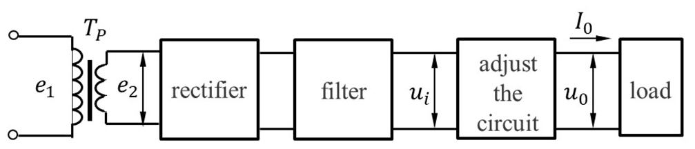
The circuit signals of lossy loads such as pulses and harmonics are filtered out through capacitor filtering, and a relatively smooth current is obtained. The general idea is shown in Fig. 17.
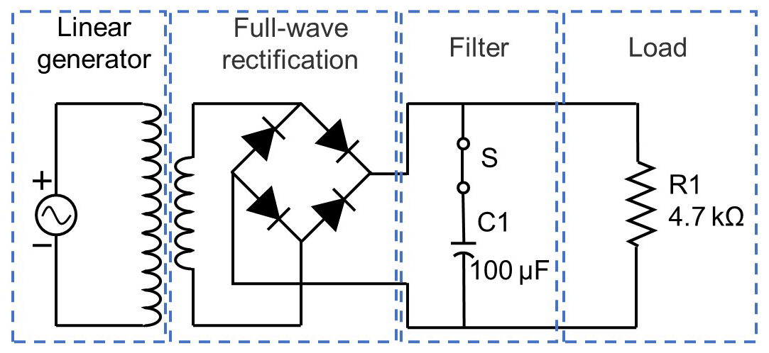
Input the no-load voltage of the electromagnetic simulation into the power supply, perform full-wave rectification to stabilize the voltage pulse, and reduce the damage to the load appliances. The rectifier filter circuit diagram is shown in Fig. 18.
In order to improve the efficiency, the thinner wire should be used to increase the number of turns to obtain higher output voltage and reduce the power loss on the circuit components. However, there are additional costs in the production of too thin of a wire rod. If the economic conditions permit, the appropriate coil diameter can be selected according to the external load, and the coil turns can be calculated.
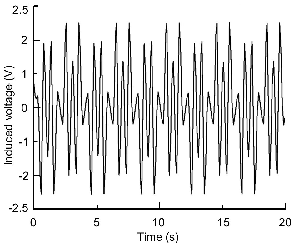
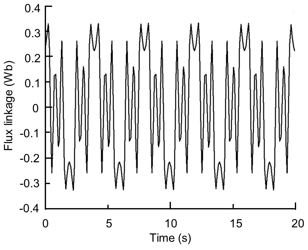
Finally, this design will select the wire with a diameter of about 0.4 mm, and the number of turns is 830. After the coil turns are set in MAXWELL, a winding is added as a twisted pair, and the coil set before is added to the winding. In order to determine the better moving speed of the translator, the simulation analysis of no-load voltage is carried out at this speed. According to the conclusion of the previous motion analysis, the speed of the translator is selected. Because the full travel of the translator is 90 mm, the velocity is calculated as follows:
The no-load voltage curve is depicted in Fig. 19. Figure 20 reveals that the flux change curve of the generator is obtained. The result shows that the output voltage amplitude can reach 2.5 V. The maximum magnetic flux amplitude in time domains is 0.3 Wb.
In this article, a 6-DOF parallel mechanism equipped with chain linear generators was designed for wave energy collection and conversion. Some conclusions can be drawn as follows.
-
Based on the theoretical analysis of dynamics, the inverse solution model of mechanism position is established. When the generator and wave parameters are known, the motion law of each branch chain can be obtained. By analyzing all the external forces of the generating mechanism in the process of motion, the dynamic differential equation is constructed and the calculation method of wave force is derived.
-
The branch chain linear generator is analyzed in detail. The results show that the axial magnetization method is conducive to the improvement of the generator performance; the pole shoe yoke can reduce the magnetic leakage and effectively improve the magnetic flux density; the amplitude of the moving speed and the angular frequency of the translator have a great effect on the electromagnetic force. When the maximum motion stroke of the generator is 90 mm, the velocity amplitude is 3π, and the electromagnetic force is the largest; when the angular frequency is 0.5π, the electromagnetic force is the minimum.
-
Combined with the electromagnetic force and spring reset force, the differential equation is solved for the heave motion of the generator platform under the given wave height and period, and the motion law is the obtained energy conversion efficiency of the motor.
-
The circuit management model of the collected electric energy is designed, and the time domain analysis of no-load voltage and magnetic flux variation under known conditions is obtained by simulation.
All the data used in this paper can be obtained from the corresponding author upon request.
TY proposed the theory of the modeling method and wrote the paper; YLW and CQ carried out numerical simulations; ZHW provided guidance on theoretical methods.
The authors declare that they have no conflict of interest.
The authors would like to thank the anonymous reviewers for their valuable comments and suggestions for revising the paper.
This work is supported by the National Natural Science Foundation of China (grant no. 51775166).
This paper was edited by Daniel Condurache and reviewed by Iosif Birlescu and one anonymous referee.
Astariz, S. and Iglesias, G.: The economics of wave energy: A review, Renew. Sust. Energ. Rev., 45, 397–408, https://doi.org/10.1016/j.rser.2015.01.061, 2015.
Bharath, A., Nader, J.-R., Penesis, I., and Macfarlane, G.: Nonlinear hydrodynamic effects on a generic spherical wave energy converter, Renew. Energ., 118, 56–70, https://doi.org/10.1016/j.renene.2017.10.078, 2018.
Cargo, C. J., Hillis, A. J., and Plummer, A. R.: Strategies for active tuning of Wave Energy Converter hydraulic power take-off mechanisms, Renew. Energ., 94, 32–47, https://doi.org/10.1016/j.renene.2016.03.007, 2016.
Castellucci, V., Garcia-Teran, J., Eriksson, M., Padman, L., and Waters, R.: Influence of Sea State and Tidal Height on Wave Power Absorption, IEEE J. Oceanic Eng., 42, 566–573, https://doi.org/10.1109/JOE.2016.2598480, 2017.
Clément, A., McCullen P., Falcão, A., Fiorentino, A., Gardner, F., Hammarlund, K., Lemonis, G., Lewis, T., Nielsen, K., Petroncini, S., Pontes, M. T., Schild, P., Sjöström, B. O., Sørensen, H. C., and Thorpe, T.: Wave energy in Europe: current status and perspectives, Renew. Sustain. Energ. Rev., 6, 405–431, https://doi.org/10.1016/S1364-0321(02)00009-6, 2002.
Dastjerdi, A. H., Sheikhi, M. M., and Masouleh, M. T.: A complete analytical solution for the dimensional synthesis of 3-DOF delta parallel robot for a prescribed workspace, Mechanism and Machine Theory, 153, 103991, https://doi.org/10.1016/j.mechmachtheory.2020.103991, 2020.
De O Falcão, A. F.: Wave energy utilization: A review of the technologies, Renew. Sust. Energ. Rev., 14, 899–918, https://doi.org/10.1016/j.rser.2009.11.003, 2010.
Drew, B., Plummer, A. R., and Sahinkaya, M. N.: A review of wave energy converter technology, P. I. Mech. Eng. A-J. Pow., 223, 887-902, https://doi.org/10.1243/09576509JPE782, 2009.
Du, Y., Cheng, M., and Chau, K. T.: Simulation of the Linear Primary Permanent Magnet Vernier machine system for wave energy conversion, 2013 International Conference on Electrical Machines and Systems (ICEMS), Busan, South Korea, 1 January 2013, 262, https://doi.org/10.1109/ICEMS.2013.6754462, 2013.
Ekergård, B., Leijon, M., Energies, and Sciubba, E.: Longitudinal End Effects in a Linear Wave Power Generator, Energies, 13, 327, https://doi.org/10.3390/en13020327, 2020.
Farrok, O. and Islam, M. R.: Advanced Electrical Machines for Oceanic Wave Energy Conversion, Springer, Singapore, 2018.
Farrok, O., Islam, M. R., Sheikh, M. R. I., Guo, Y. G., and Zhu, J. G.: Design and Analysis of a Novel Lightweight Translator Permanent Magnet Linear Generator for Oceanic Wave Energy Conversion, IEEE T. Magn, 53, 1–4, https://doi.org/10.1109/TMAG.2017.2713770, 2017.
Farrok, O., Islam, M. R., Islam Sheikh, M. R., Guo, Y., Zhu, J., and Lei, G.: Oceanic Wave Energy Conversion by a Novel Permanent Magnet Linear Generator Capable of Preventing Demagnetization, IEEE T. Ind. Appl., 54, 6005–6014, https://doi.org/10.1109/tia.2018.2863661, 2018.
Farrok, O., Islam, M. R., Muttaqi, K. M., Sutanto, D., and Zhu, J.: Design and Optimization of a Novel Dual-Port Linear Generator for Oceanic Wave Energy Conversion, IEEE T. Ind. Electron., 67, 3409-3418, https://doi.org/10.1109/tie.2019.2921293, 2020.
Gexue, R., Qiuhai, L., Ning, H., Rendong, N., and Bo, P.: On vibration control with Stewart parallel mechanism, Mechatronics, 14, 1–13, https://doi.org/10.1016/S0957-4158(02)00092-2, 2004.
Ghasemi, A., Anbarsooz, M., Malvandi, A., Ghasemi, A., and Hedayati, F.: A nonlinear computational modeling of wave energy converters: A tethered point absorber and a bottom-hinged flap device, Renew. Energ., 103, 774–785, https://doi.org/10.1016/j.renene.2016.11.011, 2017.
Furutani, K., Suzuki, M., and Kudoh, R.: Nanometre-cutting machine using a Stewart-platform parallel mechanism, Measurement Sci. Technol., 15, 467–467, https://doi.org/10.1088/0957-0233/15/2/022, 2004.
Keysan, O., Mueller, M., McDonald, A., Hodgins, N., and Shek, J.: Designing the C-GEN lightweight direct drive generator for wave and tidal energy, IET Renew. Power Gen., 6, 161, https://doi.org/10.1049/iet-rpg.2009.0213, 2012.
Leijon, M., Boström, C., Danielsson, O., Gustafsson, S., Haikonen, K., Langhamer, O., Strömstedt, E., Stålberg, M., Sundberg, J., Svensson, O., Tyrberg, S., and Waters, R.: Wave Energy from the North Sea: Experiences from the Lysekil Research Site, Surv. Geophys., 29, 221–240, https://doi.org/10.1007/s10712-008-9047-x, 2008.
Nader, J.-R., Zhu, S.-P., Cooper, P., and Stappenbelt, B.: A finite-element study of the efficiency of arrays of oscillating water column wave energy converters, Ocean Eng., 43, 72–81, https://doi.org/10.1016/j.oceaneng.2012.01.022, 2012.
Prudell, J., Stoddard, M., Amon, E., Brekken, T. K. A., and Jouanne, A. V.: A Permanent-Magnet Tubular Linear Generator for Ocean Wave Energy Conversion, IEEE T. Ind. Appl., 46, 2392–2400, 2010.
Qiu, S. and Wang, H.: A Novel Segmented Structure and Control Method for a Permanent-Magnet Linear Generator to Broaden the Range of Efficient Energy Capture, J. Marine Sci. Eng., 7, 101, https://doi.org/10.3390/jmse7040101, 2019.
Son, D., Belissen, V., and Yeung, R. W.: Performance validation and optimization of a dual coaxial-cylinder ocean-wave energy extractor, Renew. Energ., 92, 192–201, https://doi.org/10.1016/j.renene.2016.01.032, 2016.
Tarrant, K. and Meskell, C.: Investigation on parametrically excited motions of point absorbers in regular waves, Ocean Eng., 111, 67–81, https://doi.org/10.1016/j.oceaneng.2015.10.041, 2016.
Temiz, I., Leijon, J., Ekergård, B., and Boström, C.: Economic aspects of latching control for a wave energy converter with a direct drive linear generator power take-off, Renew. Energ., 128, 57–67, https://doi.org/10.1016/j.renene.2018.05.041, 2018.
Tong, Z., Gosselin, C., and Jiang, H.: Dynamic decoupling analysis and experiment based on a class of modified Gough-Stewart parallel manipulators with line orthogonality, Mechanism and Machine Theory, 143, 103636, https://doi.org/10.1016/j.mechmachtheory.2019.103636, 2020.
Zhang, J., Yu, H., and Shi, Z.: Analysis of a PM Linear Generator with Double Translators for Complementary Energy Generation Platform, Energies, 12, 4606, https://doi.org/10.3390/en12244606, 2019.
Zhu, S., Cheng, M., Hua, W., Cai, X., and Tong, M.: Finite Element Analysis of Flux-Switching PM Machine Considering Oversaturation and Irreversible Demagnetization, IEEE T. Magn., 51, 1–4, https://doi.org/10.1109/TMAG.2015.2445774, 2015.