the Creative Commons Attribution 4.0 License.
the Creative Commons Attribution 4.0 License.
 | 07 Apr 2021
Geometric synthesis method of compliant mechanism based on similarity transformation of pole maps
Song Lin
Hanchao Wang
Jingyu Jiang
Niels Modler
This paper presents a geometric synthesis method for compliant mechanisms based on similarity transformation of pole maps. Motion generation is a typical and common mechanism synthesis task, so this study takes it as the design requirement to expound the proposed method. Most of the current research work relies on numerical solution of the nonlinear Bernoulli–Euler beam model, numerical simulations or physical experiments to study the synthesis method of compliant mechanisms. There is a lack of simpler and more efficient methods to achieve motion generation of compliant mechanisms with various topologies. This study is based on pole map which is a geometric tool to describe the motion of rigid-body mechanisms. In this paper, we first demonstrate the feasibility of applying the similarity transformation of pole map to compliant mechanisms. It is proved that the pole map of compliant mechanisms has the same characteristic as rigid-body mechanisms during similarity transformation. Then we present the procedure of synthesis method in detail and expound the establishment method of function module which can avoid the functional defects of the final designed mechanism. At last, we take the compliant geared linkages and compliant four-bar linkage as examples to illustrate the novel synthesis approach. The result is an applicable and effective synthesis method for motion generation of compliant mechanisms.
- Article
(1902 KB) - Full-text XML
- BibTeX
- EndNote


The compliant mechanism can be defined as a mechanism that obtains some of its motion by means of the deformation of elastic elements (Howell, 2001). If the length of the compliant section is similar to the length of the rigid section, the geometric nonlinearity caused by large bending displacements must be considered (Kimball and Tsai, 2002). At present, researchers have developed many methods for analyzing the large deflection of flexural beams, such as elliptical integral method, beam constraint model, Adomian decomposition method, pseudo-rigid-body model (PRBM), and non-linear finite element analysis method (FEA). Based on these studies, researchers can design compliant mechanisms. Midha et al. (1994) introduced the kinematics-based design method. The theoretical approach using the numerical solution of the nonlinear Bernoulli–Euler beam model is one of the most common analysis and design methods, but its calculation process is very complicated (DeBona and Zelenika, 1997). Howell and Midha (1994) created the synthesis approach based on PRBM, and it can provide a practical means for analyzing and designing the compliant mechanism. Li et al. (2017) proposed 3R PRBM method and used it to analyze and design compliant mechanisms. In the field of compliant linkage synthesis, Bagivalu Prasanna et al. (2020) introduced a methodology to determine the possible deflected configuration of a compliant four-bar mechanism for a given set of load or displacement boundary conditions. Valentini and Pennestri (2018) presented an original methodology for addressing the kinematic synthesis of a compliant four-bar mechanism by using PRBM. Alqasimi et al. (2016) designed a linear bistable compliant crank–slider mechanism by using PRBM to solve the kinetic and kinematic equations. Hanke et al. (2015) presented a graphical synthesis algorithm and used this method to solve two-position synthesis of planar compliant mechanisms. Huang and Schimmels (2019, 2020) researched the synthesis method of compliant five-bar linkages and presented a geometric approach to the passive realization of any given planar compliance with a six-joint fully serial or six-spring fully parallel mechanism. Topology optimization method has been widely used in the design of distributed compliant mechanisms (Zhou and Mandala, 2012; Patiballa and Krishnan, 2017; Liu et al., 2017), but it commonly leads to complex structures that may cause higher manufacturing costs using elastic material. Diab and Smaili (2017) presented an ants-search-based method for optimum synthesis of compliant mechanisms under various design criteria. Choi and Cho (2020) presented a configuration and sizing design optimization method for large deformation planar compliant mechanisms.
Since it is difficult to analyze the displacement of elastic elements or flexural beams during the deformation, the synthesis method of compliant mechanisms is usually not as systematic as rigid-body mechanisms. Therefore, the novel efficient and simple approach is the focus in the research field of compliant mechanism synthesis. The motion generation of compliant mechanisms can be used to solve some practical engineering problems, such as using compliant mechanisms to replace rigid-body mechanisms for avoiding disadvantages of rigid-body mechanisms or achieving the guidance task of some light-weight products. Thus, the goal of this study is to explore a new method for motion generation of compliant mechanisms. Lin et al. (2018) proposed a method to describe the finitely separated positions by using the pole map. Taking this method as the fundamental principle, Lin et al. (2018) use pole maps as unified geometric identification between the guidance mechanisms and given positions. By performing similarity transformation on a certain basic mechanism, a geometric synthesis approach for planar motion generation is proposed. This method can be applied to the design of rigid-body mechanisms with various types. However, this geometric synthesis approach has not been used in the design of compliant mechanisms, and it lacks practical and effective calculation procedures for the synthesis of more than three positions. Therefore, still using the pole maps as geometric tool to describe planar positions, this paper will study the feasibility of the similarity transformation of compliant mechanisms and propose a novel method for motion generation of compliant mechanisms.
Although the principle of similarity transformation of pole map has been applied to the motion analysis of rigid-body mechanisms, it is not clear whether it can be applied to compliant mechanisms. Hence this paper first demonstrates the feasibility of applying this principle to compliant mechanisms. The geometric similarity of deformation curves, which are formed by flexural beams with different lengths, is discussed, and it is proved that the pole map of compliant mechanisms has the same characteristic as rigid-body mechanisms during similarity transformation. Then this paper presents the detailed procedure of synthesis method. Next, the function module is introduced as the basis of mechanism synthesis, which can achieve the functional characteristics required by the design. Finally, this study illustrates the synthesis approach with two examples of three-position and four-position motion generation. Compared with other methods, the synthesis method proposed in this paper is based on geometric similarity transformation, and hence it can avoid the overly complicated mathematical calculation. Function module is introduced at the beginning of the design process, so this method can ensure that the final solution mechanism will satisfy the functional characteristics of design requirements, such as the trajectory shape of the guidance point, the rotation angle range of the guidance link, the workspace and the mounting position of the fixed frame, etc. In addition, this method is not limited to the design of a specific type of compliant mechanism, and it can be applied to compliant mechanisms with various topological structure.
2.1 Position changes described by pole map
Prescribed positions can be described by n−1 poles relative to the initial position Ej(Uj,βj) and their corresponding rotation angles (Lin et al., 2018). The shape formed by these poles is defined as pole map. As shown in Fig. 1, the initial position E1 can reach E2, E3 and E4 by rotating around P12, P13 and P14 respectively, so the triangle P12P13P14 forms the pole map. Given any two plane positions Ej(Uj,βj) and Ek(Uk,βk), the pole Pjk can be determined by a complex number as (Lin et al., 2018)
where .

2.2 Geometric identification of moving planes
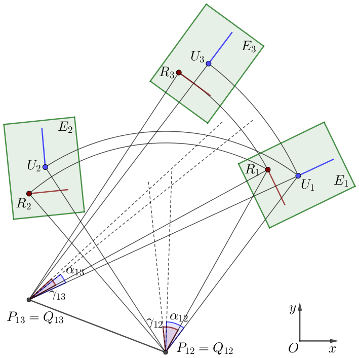
The displacement of finitely separated positions can be represented by a pole map. If the two pole maps are geometrically identical (i.e., the pole coordinates and corresponding angles in the first pole map are equal to those in the second pole map respectively), then the two displacements represented by the two pole maps are the same. As shown in Fig. 2, the displacement of plane positions U1, U2 and U3 determines the pole map P12P13, and the displacement of plane positions R1, R2 and R3 determines the pole map Q12Q13. If P12=Q12, α12=γ12, P13=Q13, α13=γ13, then the two series of displacements are the same, so positions Ui and Ri can be considered in the same motion plane Ei. Therefore, the pole map can be regarded as the identification for motion planes.
2.3 Geometric similarity of the pole map of rigid-body mechanisms
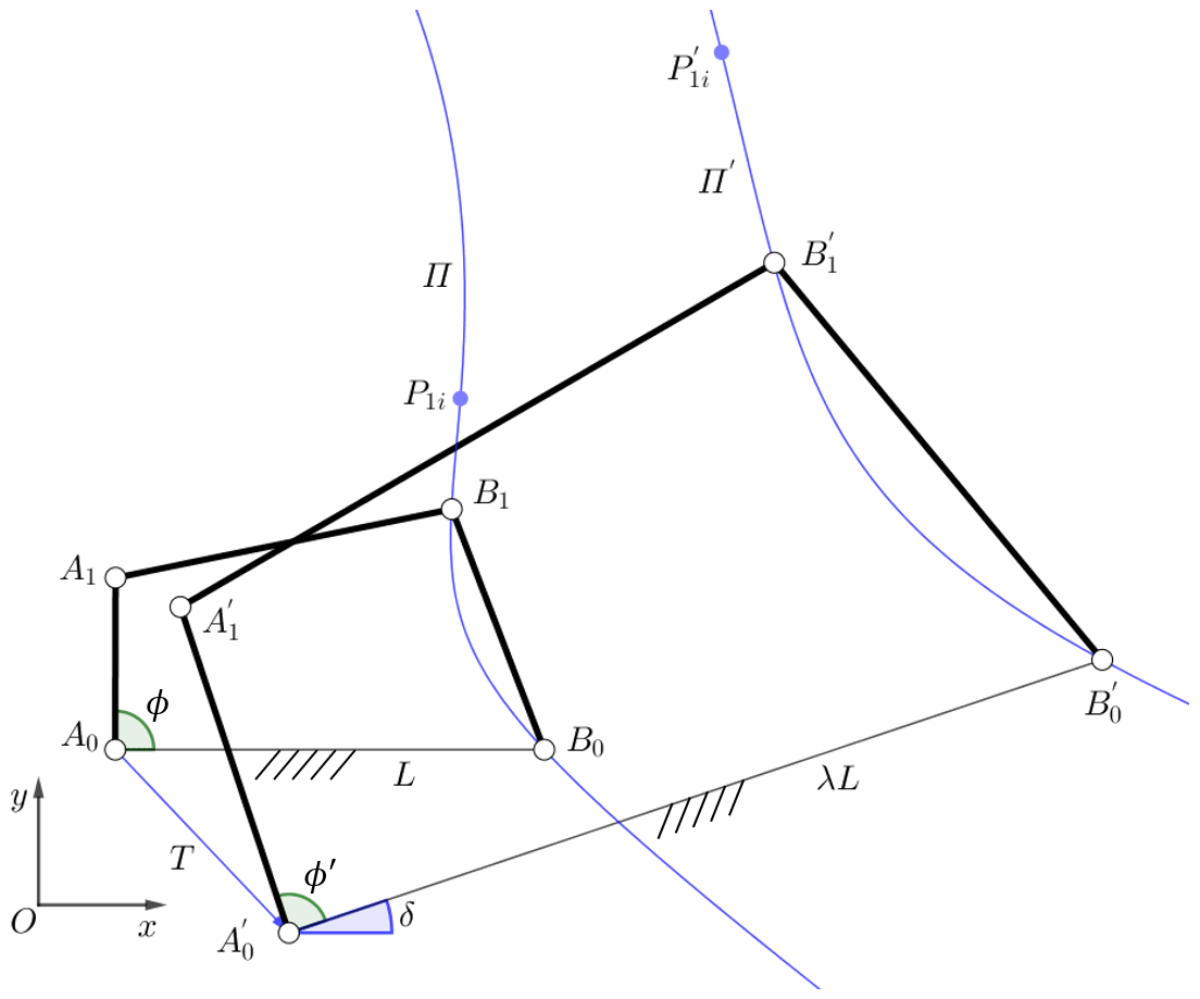
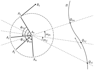
For any rigid-body mechanism, the position Ei(Ui,βi) of a certain component during the motion can be described by the initial position E1(U1,β1) and pole P1i, and the pole map determined by the continuous displacement of the component is a pole curve. If the mechanism is subjected to geometric similarity transformation including translating, rotating and scaling, to obtain a new mechanism, then the finitely separated positions E1E2…En of the original mechanism will be transformed to new positions . The relationship between the original pole map P12P13…P1n and the new pole map is geometric similarity, which is the same as the similarity relationship between the two mechanisms. For example, in the planar mechanism A0A1B1B0 shown in Fig. 3, the initial angle is , and P1i is the pole of guidance link A1B1 in the motion position of ϕ=ϕi. Mechanism is obtained by geometrically transforming the original mechanism A0A1B1B0, and can be obtained by calculating the pole of link in the motion position of . Then the pole curve Π formed by P1i is geometrically similar to the pole curve Π′ formed by .
3.1 Geometric similarity of flexural beam
As shown in Fig. 3, the rigid-body mechanism has geometric similarity during the geometric transformation process, while the pole maps before and after the transformation also have the same geometric similarity. However, because of the complexity of the force and deformation, the feature of compliant mechanisms during the geometric transformation cannot be directly analogized from the law of rigid-body mechanisms. In order to study the feasibility of applying the similarity transformation of pole maps to compliant mechanism, it is necessary to demonstrate that the compliant mechanism and its pole maps both have the geometric similarity in translating, rotating, and dimension scaling, just like the transformation feature of rigid-body mechanism shown in Fig. 3. First, this paper will analyze the deformation of the flexural beam which satisfies the Bernoulli–Euler beam equation.
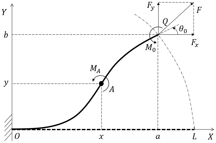
Figure 4 shows the deformation of a cantilever beam subject to a combined end force and external bending moment. The coordinate frame is established by taking the fixed end as the coordinate origin and the direction of initially straight beam as the positive direction of x axis. The end force F can be decomposed into a horizontal force Fx and a vertical force Fy. The coordinates of the free end Q are (a,b). Point A, whose position is denoted by (x,y), is an arbitrary point on the beam, and the curvature at A is
The curve equation of the beam deformation can be expressed by arc length s, that is, . Differentiating Eq. (2) with respect to s, we obtain
According to the differential geometry, the formula is known. Differentiating this formula with respect to s yields
Since , it can be differentiated as . We continue to differentiate this equation and get . Substituting into the equation leads to
According to Eqs. (4) and (5), we have
Next, we calculate , the denominator of the right side of Eq. (6). Since , the expression can be expanded and derived as
Substituting and into the above equation yields . Considering the direction of the tangent vector and the normal vector at point A, we obtain ,,,, κ>0, and hence
Substituting the above formula into Eq. (6) gives
As shown in Fig. 5, a flexible beam with a length of L is under the action of the end loads F1(Fx1Fy1) and M1. The position of the free end point is denoted by (a1,b1), and the curve equations of beam deformation are denoted by x1(s) and y1(s). According to Eqs. (2), (3) and (7), the differential equations describing the curve can be calculated as shown in the following.
where a1=x1(L), b1=y1(L). When , x1(s) and y1(s) satisfy the differential equations of Eq. (8).

If this flexural beam is scaled by the scaling factor λ while the material and section shape remain the same, the length of the new beam is λL and the flexural rigidity EI remains unchanged, as shown in Fig. 5.
Subject to the end load F2(Fx2,Fy2) and M2, the position of free end point is (a2,b2), and curve equations representing the new beam are determined by the following differential equations.
Supposing
and then successively differentiating Eq. (10), we can obtain , , , , , . From Eq. (10), we can get and .
Substituting the above calculation results and Eq. (10) into Eq. (9), we have
where . If the end load satisfies the functional relationship given by Eq. (11), the above equations are obviously the same as Eq. (8).
Therefore, under the condition that the free end load satisfies Eq. (11), if x1=x1(s) and y1=y1(s) are the solutions of differential equations in Eq. (8), then and are the solutions of differential equations in Eq. (9). That is, for two flexural beams whose lengths are L and λL respectively, when the free end load satisfies Eq. (11), the deformation curves of beams have geometric similarity which can be written as
It is easy to prove that during the scaling process of the compliant beam, the position of the free end point corresponding to the same end angle is also scaled in the same way. Similarly, the end point trajectory before and after scaling is also scaled, as shown by Π1 and Π2 in Fig. 5.
3.2 Geometric similarity of compliant mechanism
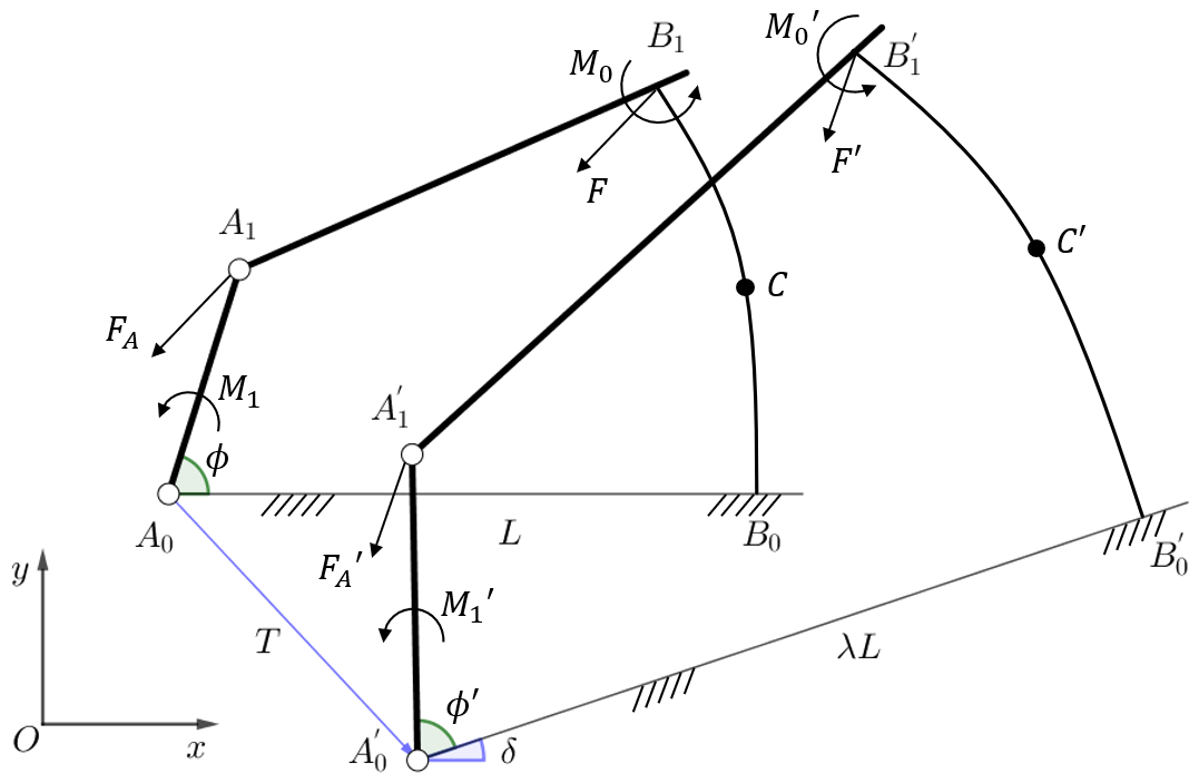
The scaling of flexural beams is discussed in Sect. 3.1, and then this paper will study the geometric similarity of the whole compliant mechanism during geometric transformation. Taking a typical mechanism as an example, the planar linkage A0A1B1B0 is a compliant mechanism, as shown in Fig. 6. The initially straight flexural beam B0B1 is fixedly connected with rigid link A1B1, and C is an arbitrary point in the mechanism. It is assumed that this compliant linkage maintains a static balance throughout the entire range of motion. When the input angle ϕ=ϕ0, the force that link A0A1 applies to link A1B1 is denoted by FA, and the driving torque is denoted by M1. At this time, the moment and force which link A1B1 applies to link B0B1 are denoted by M0 and F, respectively.
According to static analysis of link A1B1 and A0A1, we obtain
Using F=FA, the formula of M1 can be obtained by adding the above two equations, i.e.,
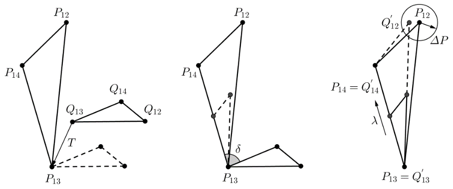
If the initial compliant linkages A0A1B1B0 in the motion position of ϕ=ϕ0 are subjected to a geometric transformation which takes A0 as a base point, T as a translating factor, δ as a rotating factor and λ as a scaling factor, and at the same time the flexural rigidity EI remains unchanged, then the transformation will obtain a new compliant linkage . The relevant parameters are all shown in Fig. 6. After the transformation, the new position of any point C in the linkages is
We assume that the compliant mechanism shown in Fig. 6 is in static equilibrium. According to Eq. (14), if point C is on the flexural beam, then the deformation curve of is . Obviously, the deformation curves of flexural beam and B0B1 have geometric similarity. Using Eq. (11) and geometric relationship illustrated by Fig. 6, we obtain
Now we analyze the static balance of link . Using Eq. (14), we have , and hence the moment of point can be calculated and written as . Since , the compliant mechanism shown in Fig. 6 is in a state of static equilibrium.
Therefore, for the compliant mechanism A0A1B1B0 at any position in the motion range, if , then the transformed mechanism and the original mechanism always have a geometric similarity relationship.
According to Eq. (13), the driving force of the transformed mechanism can be calculated, i.e., . Substituting Eq. (15) into the expression of and simplifying, we obtain
It can be seen that if the driving force satisfies the relationship of Eq. (16), the planar compliant mechanism has geometric similarity before and after the transformation of translating, rotation and scaling. The position coordinates of any point on the mechanism satisfy the transformation formula given by Eq. (14).
In the following, this paper will discuss the transformation rules of poles and pole maps during the geometric transformation of compliant mechanism. For any mechanism containing flexible component, which can be denoted by A0A1…An, the pole of two given motion position Ej(Uj,βj) and Ek(Uk,βk) of a link can be represented as Pjk(αjk), and Eq. (1) is the formula for calculating the pole. If the initial compliant mechanism is subjected to a geometric transformation which takes A0 as a base point, T as a translating factor, δ as a rotating factor and λ as a scaling factor, then we will obtain a new compliant mechanism . According to Eq. (14), two motion positions after geometric transformation can be written as and , where . The pole of motion positions and can be calculated by Eq. (1), and it can be written as
where . The above equation can be simplified into the form
Eq. (17) shows that before and after the geometric transformation of any compliant mechanism, the poles are also subjected to the same geometric transformation, and obviously the pole maps of original mechanism and transformed mechanism always have a geometric similarity relationship. It can be concluded that if the flexural rigidity EI maintains unchanged, then the finitely separated motion positions, poles and pole maps are similar before and after the geometric transformation. This similarity law of compliant mechanisms is the same as that of rigid-body mechanisms shown in Fig. 3.
3.3 Geometric approach to compliant mechanism synthesis
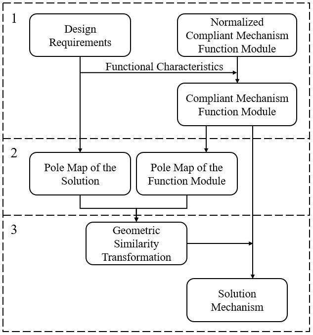
In Sect. 3.2, the geometric similarity of the pole map during the geometric similarity transformation of compliant mechanisms is demonstrated. Based on this theory, a novel geometric approach for compliant mechanism synthesis is proposed. Next, this paper will expound the new synthesis method in detail, which can be divided into three main contents as shown in Fig. 7.
-
According to the mechanism type or topological structure characteristics specified by design requirements, a certain type of nondimensional compliant mechanism is chosen. Then the dimension parameters of this mechanism are adjusted and determined so that the mechanism can satisfy the functional characteristics of design requirements, such as the trajectory shape of the guidance point, the rotation angle range of the guidance link, the workspace and the mounting position of the fixed frame, etc. This chosen nondimensional mechanism is defined as a function module, whose establishment will be discussed in Sect. 4.
-
Analyzing the motion generation task specified by the design requirement, the given finitely separated positions of the final solution mechanism can be obtained so that the pole map P and its corresponding angles of the solution mechanism can be calculated. Next, the pole curve of the function module is calculated, and some poles on the curve are selected so as to form a pole map Q geometric similar to the pole map P while ensuring that the angles corresponding to each pole in Q and P are respectively equal. The formula for calculating the pole map is presented by Eq. (1).
-
By geometric similarity transforming Q, namely translating, rotating and scaling, the transformed pole map can be identical to P. According to the conclusion of Sect. 3.2, during the geometric similarity transformation of the compliant mechanism, the pole map is subjected to the same transformation. Therefore, if the function module is transformed by following the method of making Q identical to P, then the pole map of the new transformed mechanism is exactly P. According to the theory that the same pole map represents the same finitely separated positions, as illustrated by Fig. 2, this new compliant mechanism can satisfy the functional characteristics of design requirements and achieve the task of motion generation.
For three-position synthesis, the proposed method can obtain multiple exact solutions. In engineering practice, most of design tasks require that the guidance link must achieve exactly at the start position and the end position while passing through the intermediate positions with given tolerances, which is named as fuzzy positions. Therefore, for four-position motion generation, we can usually allow one of the positions to become a fuzzy position. Relative to the exact position Ek(Uk,βk), the fuzzy position is restricted to a tiny translation, and the design task can give the tolerance .
The pole map of four-position motion generation is a triangle, as shown in Fig. 8, and the tolerance of the pole corresponding to the fuzzy position can be calculated by Eq. (1), i.e.,
Assuming that given positions of the design task are E1, , E3 and E4, we can adjust the initial rotation angle ϕ1 of the driving link to obtain the appropriate pole map Q12Q13Q14, which is quasi-similar to the pole map P12P13P14. As shown in Fig. 8, after similarity transformation, should be quasi-congruent to P12P13P14 while satisfying the condition .
This paper establishes the function module of compliant mechanisms and takes it as the basic object of geometric similarity transformation. At the beginning, we need to choose a compliant mechanism as a normalized function module that is likely to achieve the functional characteristics required by the design. Then we will analyze the normalized function module and obtain its kinematic equations expressed by variables. Finally, by using the kinematic equation, dimension parameters of the mechanism are adjusted and determined so that the function module can satisfy the functional characteristics of design requirements.
4.1 Modeling of the flexural beam
This paper uses 3R PRBM to analyze the deformation of the flexural beam, as shown in Fig. 9. Su (2009) presents the optimized parameters, i.e., kΘ1=3.51, kΘ2=2.99, kΘ3=2.58, γ0=0.1, γ1=0.35, γ2=0.40, γ3=0.15.

The nondimensional forward kinematic equations are
where L is the actual length of the flexural beam, c1=cos(Θ1), , , and s1, s12, s123 are also similar abbreviations.
The nondimensional statics equations are
where [J]−1 is written as (Su, 2009)
4.2 Function module of compliant geared linkage
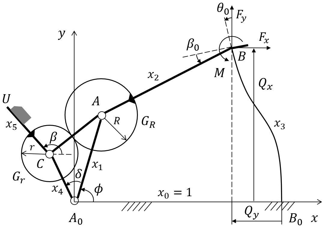
This paper will take the compliant geared linkage as an example to illustrate the establishment method of the function module. In the compliant four-bar mechanism A0ABB0, a pair of gears are mounted on the driving link A0A, as shown in Fig. 10. The rigid-body coupler AB is fixedly connected to the initially straight flexural beam BB0, and there is a constant angle between these two links. Gear GR is fixedly connected to AB, and gear Gr is connected to the guidance link CU. All absolute dimensions should be converted into relative dimensions that are ratios of component dimensions to the frame length L0, so as to obtain the normalized function module. For example, , where L3 denotes the length of flexible beam BB0. All other parameters are labeled in Fig. 10.
Closed-loop equation of compliant four-bar mechanism can be decomposed into
where θ0, and can be calculated by Eq. (19)
The force and moment that link AB applies to link BB0 are denoted as Fx, Fy and M, as shown in Fig. 10. The compliant mechanism is usually applied to products with small external load or uses rigid parts as working component such as multistable compliant mechanisms, so the external load applied by the link CU can be set equal to 0. Then the moment balance equation is
where the magnitude of AB is the actual length of link AB, namely L2. According to the angles and positions shown in Fig. 10, we can decompose vectors of Eq. (22) and obtain
According to the direction of forces in Figs. 9 and 10, we have and Fy=fx, so Eq. (23) can be rewritten into the nondimensional form
Substituting the results of Eq. (20) into the Eq. (24) and then combining with Eq. (21), we can get three equations of unknown variables Θ1, Θ2 and Θ3, which represent the three angles in PRBM. Given the crank angle ϕ, we can use Newton–Raphson method to calculate the numerical solution of Θ1, Θ2 and Θ3 and obtain the value of θ0 by substituting the calculated numerical solution into Eq. (19).
The formula of guidance angle β(ϕ) can be derived, that is
where βr is a constant related to the initial position of the link CU, and .
The trajectory equation of guidance point U can be written as
The deformation of the function module should be within the possible deformation range of the flexural beam, otherwise the final solution will not meet the practical requirements.
4.3 Adjustment of function module
In order to obtain the final function module of the compliant mechanism, we need to find the appropriate mechanism dimension according to the functional requirements of motion generation task. The general functional requirement is the guidance characteristic of the mechanism, such as the trajectory shape of the guidance point, the rotation angle range of the guidance link, the functional relationship between the input angle and the output angle, etc. Because the guidance characteristic changes with the dimension, it is necessary to analyze the effect of the dimension on the output motion of the guidance component. If the output motion is not sensitive to the dimensional changes of some components, then the dimensional constraints of these components can be appropriately reduced. On the contrary, if the output motion is sensitive to the dimensional changes of some components, the effect of these dimensions on guidance characteristics needs to be analyzed in detail. If the design task is too special or the functional requirements is too strict, we cannot find an appropriate function module that satisfies the functional requirements specified by the design task.
Through computer mathematical software or interactive geometry software, we can easily adjust dimension parameters of the function module and analyze the kinematics visually in real time so that we can intuitively understand the effect of different dimensions on the functional characteristics. Taking the compliant mechanism shown in Fig. 10 as an example, this paper will present the process of analyzing the effect of dimensions on the guidance characteristic. Now we set all dimensions of this mechanism as x1=0.6, x2=1.2, x3=1.4, x4=0.4, x5=0.4, β0=45∘, δ=90∘, ρ=1 and βr=0∘ and then adjust the parameters respectively while keeping other parameters unchanged. The functional relationship between the guidance rotation angle and the input angle can be calculated by Eq. (25), and the trajectory of guidance point U can be obtained from Eq. (26), whose results are shown in Figs. 11 and 12.
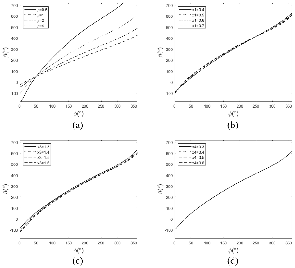
Figure 11The effect of parameters on rotation angle of the guidance link. (a) ρ. (b) x1. (c) x3. (d) x4.

Figure 12The effect of parameters on trajectory of the guidance point. (a) x1. (b) x3. (c) x4. (d) δ.
Obviously, the compliant geared linkage has the characteristic of a large range of guidance angle that is primarily linear with the input angle, and the change of main parameters does not affect the basic type of guidance characteristic. It can be seen from Fig. 11 that x1 and x3 have little effect on β, x4 does not affect β, and ρ has a large effect on β. It can be seen from Fig. 12 that x1 and x3 have little effect on the trajectory of the guidance point, x4 can scale the trajectory curve, and δ can rotate the trajectory. Therefore, the dimension of the basic compliant four-bar linkage has less effect on guidance characteristic. When selecting dimensions of the function module, it is necessary to preferentially adjust parameters of the gear part according to the given design requirements, so as to obtain a suitable mechanism. In addition, we should determine the appropriate initial position of the function module so that range of guidance angle must meet the condition
where βk max and βk min denote the maximum and minimum angle of the design requirement, and Δβ is the range of guidance angle.
In this section, two applications of exact three-position synthesis and fuzzy four-position synthesis are presented to illustrate how the proposed approach is applied.
5.1 Three-position synthesis of compliant geared linkage
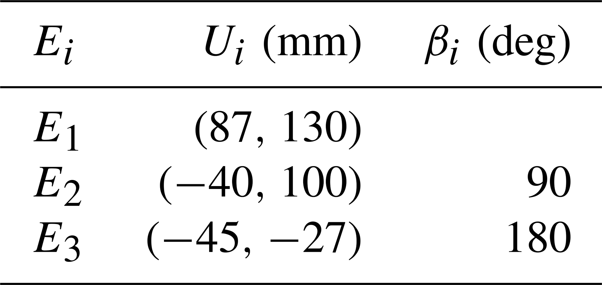
The task is to design a three-station transfer device, which is used to detect some light-weight products on the production line. These three stations are three fixed planar positions, and the device should make the product reach these positions accurately. At position E1, the product on the production line is automatically placed in the pallet of device. At position E2, the product is detected, scanned and recorded by other equipment. At position E3, the product is taken out. In order to avoid interference with the workspace of the detection, loading and unloading equipment, the design task requires that the mounting position of the transfer device should be far away from the three stations. The three given positions are shown in Table 1.
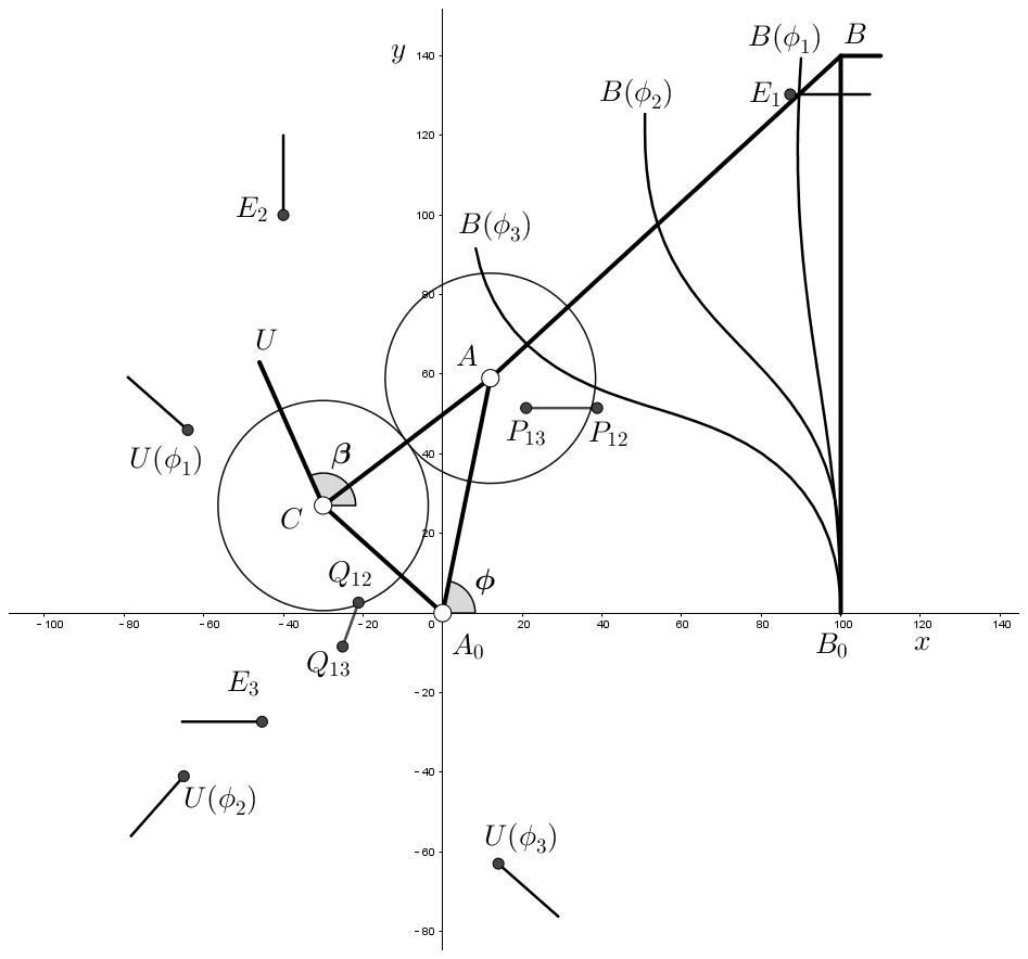
Considering that the overall size of the transfer device is small, in order to reduce the weight of the structure and the friction caused by some revolute joints, we will use compliant mechanism as the basis of this device. According to the design requirements, we can choose a compliant geared linkage to achieve three-position motion generation. The mechanism type is shown in Fig. 13: A0B0 is the driving link, CU is the guidance link installed with the pallet, and the gear ratio is 1. We will use aluminum alloy to make the flexible beam B0B, and the angle between flexible beam and the rigid-body coupler AB is 45∘. The three given positions E1, E2 and E3 are labeled in Fig. 13. The synthesis procedure can be divided into the following steps.
-
The compliant geared linkage is chosen as normalized function module. Its basic kinematic formulas are given by Eqs. (25) and (26), and relevant dimensional parameters are marked in Fig. 10. Following the method presented in Sect. 4.3, we can adjust the dimension parameters so that the function module will satisfy the functional requirement. Since the three guidance positions are required to be away from the flexural beam, we can adjust some parameters to change the position of the guidance trajectory, as shown in Fig. 12. The appropriate dimension can be determined as x0=100, x1=60, x2=120, x3=140, x4=40, x5=40, δ=60∘ and βr=0∘. According to Eq. (27), the initial rotation angle ϕ1 of the driving link can be set to ϕ=90∘.
-
The pole map of the given separated position of the design task can be calculated by substituting the data of Table 1 into Eq. (1). Taking E1 as the initial position, the poles and corresponding angles are , α12=45∘, and α13=90∘. Next, we will establish the pole map of the function module. If the position of A0 is set to the origin of the coordinate frame, then the guidance point and the guidance rotation angle of the initial position are and β(ϕ1)=138.60∘ by using Eqs. (25) and (26). Since the angle corresponding to the pole of U(ϕ1) and U(ϕ2) must be equal to α12, according to shown in Eq. (1), we have
The result is β(ϕ2)=228.60∘, and it can be substituted into Eqs. (25) and (26) so as to calculate and obtain ϕ2=135.82∘ and . In the same way we can obtain ϕ3=187.08∘, , and β(ϕ3)=318.60∘. Substituting the values of U and β into Eq. (1), the poles of the function module can be obtained, i.e., and . All relevant parameters and results are marked in Fig. 13, and we use curves to represent different deformations of flexural beam in Fig. 13.
-
Through geometric transformation, pole map Q12Q13 can be identical to pole map P12P13. Separately substituting P12, Q12 and P13, Q13 into Eq. (17) and simplifying, we obtain
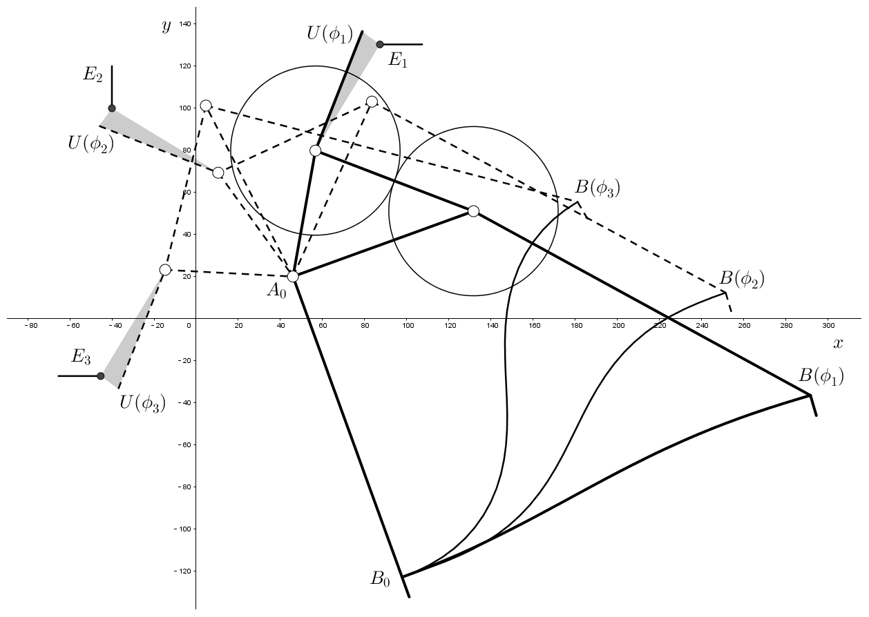
Then the factors of geometric transformation can be calculated, i.e., translating factor , rotating factor ∘ and scaling factor λ=1.52. Finally, the solution mechanism can be obtained by geometric transformation with A0 as the base point and T, δ and λ as factors, as shown in Fig. 14.
The flexure beam is made of aluminum alloy, with Young's modulus MPa, and the size of the cross section is 1.1 mm × 12 mm. We conduct finite element analysis of the flexure beam by Abaqus, as shown in Fig. 15, and deformations are the same as calculated curves shown in Fig. 14.

5.2 Four-position synthesis of compliant four-bar linkage
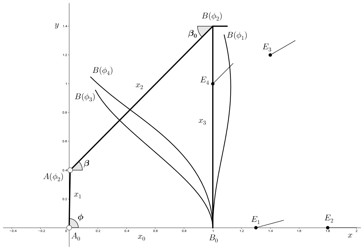
The design task is four-position synthesis of compliant four-bar linkage. The four positions are demonstrated in Table 2, and these positions are marked in Fig. 16. The tolerance of fuzzy position is given as ΔU=0.01.

The synthesis procedure can be divided into the following steps.
-
According to the mechanism type specified by design requirements, a compliant four-bar linkage shown in Fig. 16 is chosen as normalized function module, and coupler AB is the guidance link. x3 represents the length of initially straight flexural beam, x2=x3, β0=45∘. Given rotation angle ϕ, we can calculate the deflection angle θ0 of the flexural beam by following the method presented in Sect. 4.2, and hence we can get the guidance angle . Setting point B as the guidance point, its position is and .
Then we adjust the dimension parameters so that the function module will satisfy the angle range required by design task. The appropriate dimension can be determined as x0=1, x1=0.4, , x3=1.4.
-
The pole map of the given separated position of the design task can be calculated by substituting the data of Table 2 into Eq. (1). Taking E1 as the initial position, the poles and corresponding angles are , ∘, , α13=7.5∘, and α14=15∘. P12 is the pole corresponding to the fuzzy position , and we can obtain ΔP=0.038 from Eq. (18). If ϕ1 is given a numerical value, following the procedure presented in Sect. 5.1, we can calculate and obtain the pole map Q12Q13Q14. According to Eq. (29) and the geometric transformation method shown in Fig. 8, pole map can be obtained, and then the error between two pole maps is . If the value of ϕ1 changes, then ε will change. Therefore, taking ϕ1 as a variable, we can construct the numerical function relationship ε=f(ϕ1). By using a computer to calculate the minimum value of ε, the initial rotation angle ϕ1 can be determined. The result is that when ϕ1=22.83∘, ε gets the minimum value ε=0.005, which satisfies the condition ε<ΔP. Following the steps presented in Sect. 5.1, we can calculate and obtain , ϕ2=89.00∘, , ϕ3=236.59∘, , ϕ4=293.45∘ and , and the guidance angle β can also be calculated. Substituting the values of B and β into Eq. (1), the poles of the function module can be obtained, i.e., Q12(1.12, 1.65 ), , . The deformations of flexural beam in ϕ1, ϕ2, ϕ3, ϕ4 are all shown in Fig. 16.
-
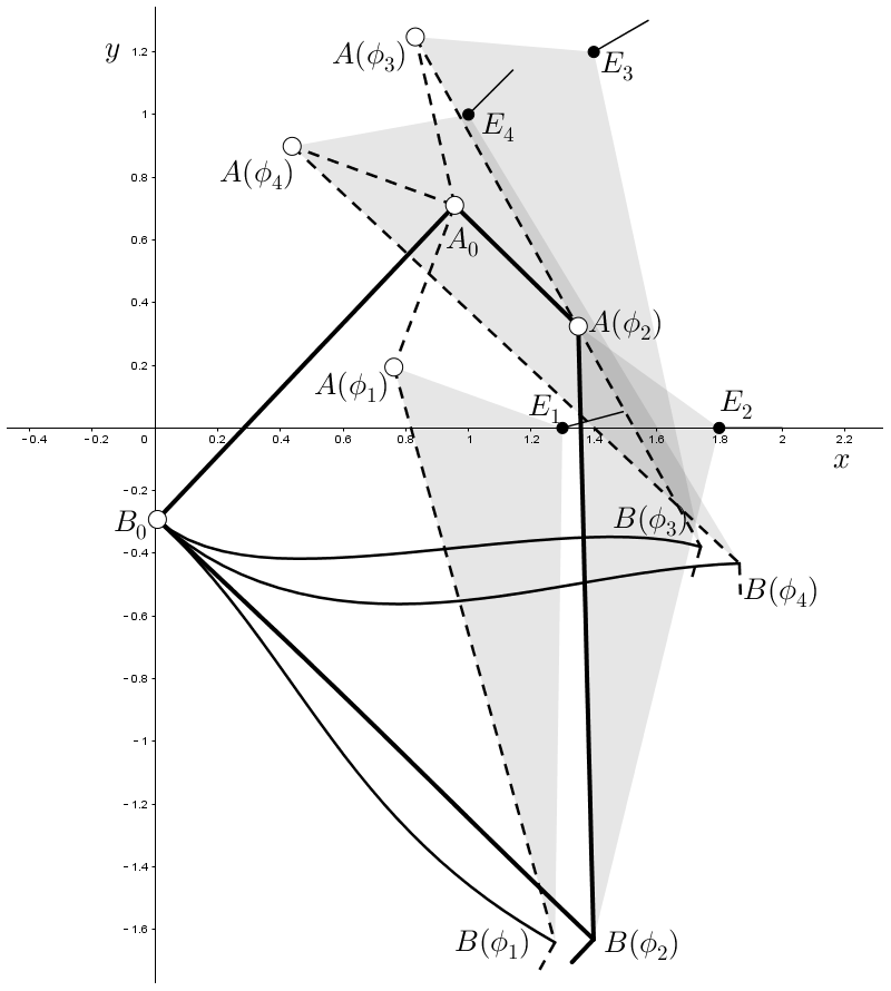
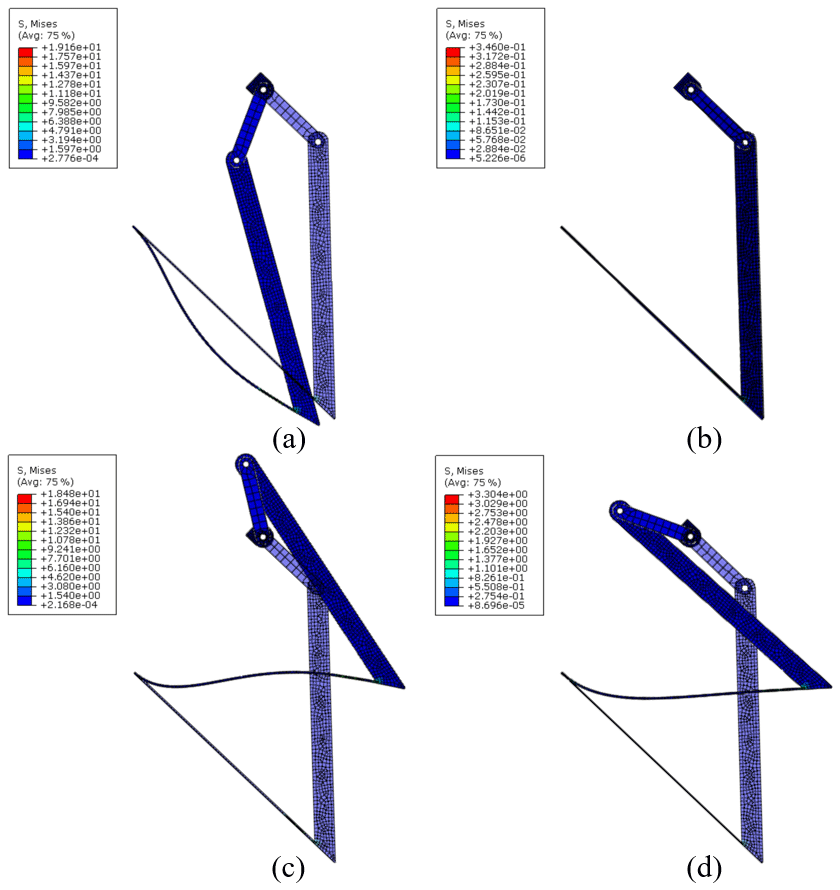
Through geometric transformation, pole map Q12Q13Q14 can be quasi-congruent to pole map P12P13P14. Using Eq. (29), the factors of geometric transformation can be calculated, i.e., , ∘, λ=1.38. Finally, the solution mechanism can be obtained by geometric transformation with A0 as the base point and T, δ and λ as factors, as shown in Fig. 17. We conduct finite element analysis of the flexure beam by Abaqus, as shown in Fig. 18, and deformations are the same as calculated curves shown in Fig. 17.
Pole maps are a geometric tool that can accurately describe multiple planar positions, and it can reveal the relationship between guidance mechanisms and given design tasks. Based on similarity transformation of pole maps, Lin et al. (2018) proposed a new approach to rigid-body mechanism synthesis and used geometric way to find the approximate solution of multi-position motion generation. Also based on similarity transformation of pole maps, this paper expands its application field and proposes a novel synthesis method for compliant mechanisms. In addition, this paper illustrates the establishment and adjustment method of the function module of compliant mechanisms and presents a practical calculation procedure for four-position synthesis through numerical example.
The first example is a practical design task of three-position motion generation, and the second example is four-position synthesis. As shown in Sect. 5.1, this method can be used to solve some practical engineering problems, such as using compliant mechanisms to replace rigid-body mechanisms for avoiding disadvantages of rigid-body mechanisms or achieving the guidance task of some light-weight products.
Compared with other methods, the synthesis method proposed in this paper is based on similarity transformation of pole map, so it is unique and has the following features.
-
Function module is introduced at the beginning of the design process, and hence this method can ensure that the final solution mechanism will satisfy the functional characteristics and transmission characteristics of design requirements. As long as we can complete kinematic and static analysis of a certain type of compliant mechanism, this type of mechanism can be chosen as a function module. Therefore, this method is not limited to the design of a specific type of compliant mechanism, and it can be applied to compliant mechanisms with various topological structure.
-
This method is based on similarity transformation of pole map, so it can avoid defects by traditional synthesis methods based on Burmester kinematic geometry theory, such as order defect. The following is the detailed discussion.
Suppose there are four motion positions: E1, Ei, Ej and En. The guidance order requires the coupler to pass through given positions in the desired order, which is relevant to the input angle order of driving link. As shown in Fig. 19, the guidance dyad A0AB passes through four given positions in the order of E1–Ei–Ej–En; then the input angle should meet the condition as . The relationship between motion positions and pole point is illustrated in Fig. 1, and thus it can be obtained that the poles Q1i, Q1j and Q1n lie on the perpendicular bisectors of A1Ai, A1Aj and A1An respectively, and the angles between each perpendicular bisector are determined as
As shown in Fig. 19, the pole is the intersection of the perpendicular bisector and the pole curve Π, so the guidance order is finally transformed to the pole order Q1i–Q1j–Q1n according to Eq. (30).
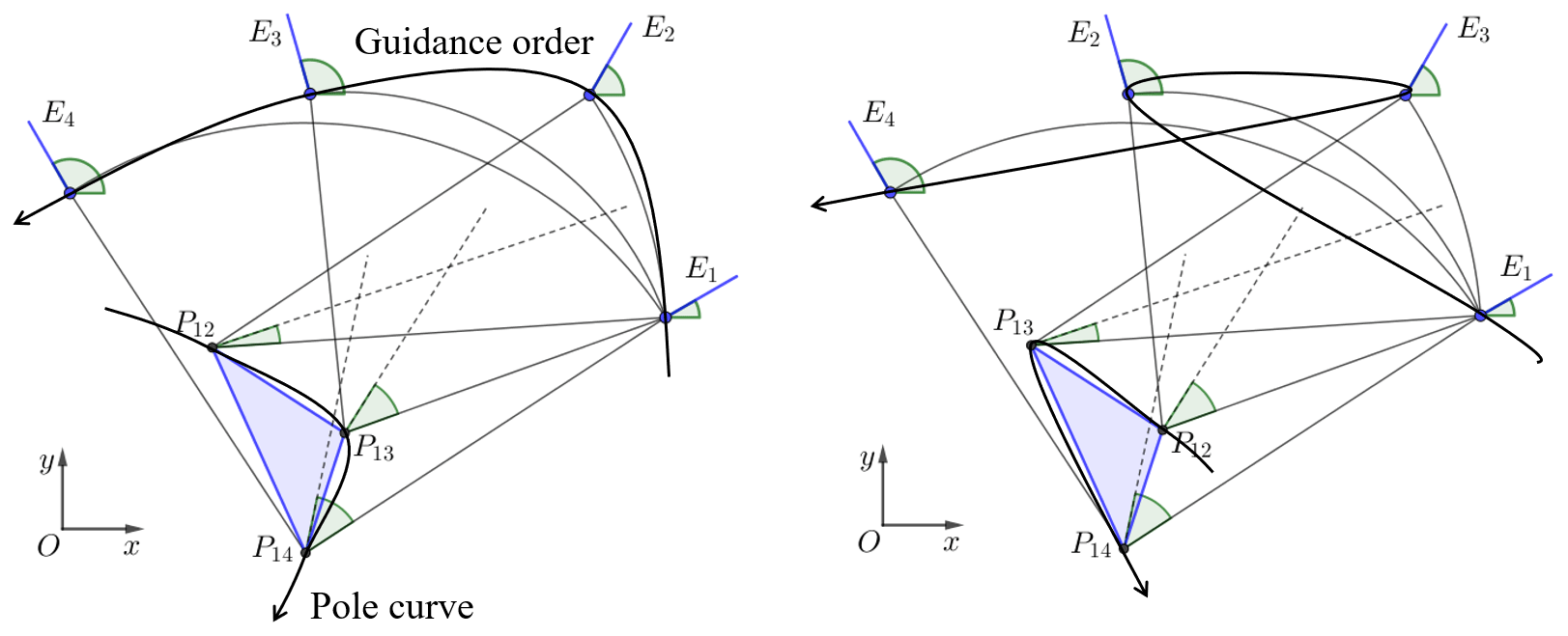
If there are two guidance tasks which have the same given positions and different guidance order, as shown in Fig. 20, obviously the shapes of the two pole maps are the same, but the pole order is different. Usually, we label motion positions and poles in the guidance order, and these two pole maps P12P13P14 in Fig. 20 are different. Because of different guidance order leading to different pole map, mechanism modules obtained by different guidance order are also different. Therefore, this method can avoid order defect.
This paper proposes a novel geometrical approach to compliant mechanism synthesis based on similarity transformation of pole maps. The study demonstrates the feasibility of applying the geometric similarity transformation to the compliant mechanism, and it is proved that the pole map of compliant mechanisms has the same characteristic as rigid-body mechanisms during similarity transformation. Then this paper proposes the procedure of synthesis method and expounds the establishment method of function module. In addition, this work illustrates the synthesis approach with two examples.
All the code used in this paper can be obtained from the corresponding author upon request.
The data are available upon request from the corresponding author.
SL and YZ proposed the methodology. YZ and HW wrote the paper. JJ and NM took part in the discussion of the paper.
The authors declare that they have no conflict of interest.
This paper was edited by Engin Tanık and reviewed by two anonymous referees.
Alqasimi, A., Lusk, C., and Chimento, J.: Design of a Linear Bistable Compliant Crank–Slider Mechanism, J. Mech. Robot., 8, 051009, https://doi.org/10.1115/1.4032509, 2016.
Bagivalu Prasanna, P., Bapat, S. G., Midha, A., and Lodagala, V.: A Methodology for Determining Static Mode Shapes of a Compliant Mechanism Using the Pseudo-Rigid-Body Model Concept and the Degrees-Of-Freedom Analysis, J. Mech. Robot., 12, 021115, https://doi.org/10.1115/1.4045971, 2020.
Choi, M. and Cho, S.: Isogeometric Optimal Design of Compliant Mechanisms Using Finite Deformation Curved Beam Built-Up Structures, J. Mech. Des., 142, 081402, https://doi.org/10.1115/1.4043585, 2020.
DeBona, F. and Zelenika, S.: A generalized elastica-type approach to the analysis of large displacements of spring-strips, Proc. Inst. Mech. Eng. Part C-J. Mech. Eng. Sci., 211, 509–517, https://doi.org/10.1243/0954406971521890, 1997.
Diab, N. and Smaili, A.: An Ants-Search based method for optimum synthesis of compliant mechanisms under various design criteria, Mech. Mach. Theory, 114, 85–97, https://doi.org/10.1016/j.mechmachtheory.2017.04.004, 2017.
Hanke, U., Hampel, P., and Comsa, A.: Compliant Mechanism Synthesis by Using Elastic Similitude, Chin. J. Mech. Eng., 28, 769–775, https://doi.org/10.3901/CJME.2015.0520.069, 2015.
Howell, L. L.: Compliant Mechanisms, John Wiley & Sons, New York, USA, 2001.
Howell, L. L. and Midha, A.: A Method for the Design of Compliant Mechanisms with Small-Length Flexural Pivots, J. Mech. Des., 116, 280–290, https://doi.org/10.1115/1.2919359, 1994.
Huang, S. and Schimmels, J. M.: Geometry based synthesis of planar compliances with redundant mechanisms having five compliant components, Mech. Mach. Theory, 134, 645–666, https://doi.org/10.1016/j.mechmachtheory.2018.12.021, 2019.
Huang, S. and Schimmels, J. M.: Synthesis of Planar Compliances With Mechanisms Having Six Compliant Components: Geometric Approach, J. Mech. Robot., 12, 031013, https://doi.org/10.1115/1.4045648, 2020.
Kimball, C. and Tsai, L.: Modeling of Flexural Beams Subjected to Arbitrary End Loads, J. Mech. Des., 124, 223–235, https://doi.org/10.1115/1.1455031, 2002.
Li, N., Su, H., and Zhang, X.: Accuracy Assessment of Pseudo-Rigid-Body Model for Dynamic Analysis of Compliant Mechanisms, J. Mech. Robot., 9, 054503, https://doi.org/10.1115/1.4037186, 2017.
Lin, S., Liu, J., Wang, H., and Zhang, Y.: A novel geometric approach for planar motion generation based on similarity transformation of pole maps, Mech. Mach. Theory, 122, 97–112, https://doi.org/10.1016/j.mechmachtheory.2017.11.027, 2018.
Liu, C., Huang, G., and Chen, T.: An Evolutionary Soft-Add Topology Optimization Method for Synthesis of Compliant Mechanisms with Maximum Output Displacement, J. Mech. Robot., 9, 054502, https://doi.org/10.1115/1.4037000, 2017.
Midha, A., Norton, T. W., and Howell, L. L.: On the Nomenclature, Classification, and Abstractions of Compliant Mechanisms, J. Mech. Des., 116, 270–279, https://doi.org/10.1115/1.2919358, 1994.
Patiballa, S. K. and Krishnan, G.: Estimating Optimized Stress Bounds in Early Stage Design of Compliant Mechanisms, J. Mech. Des., 139, 062302, https://doi.org/10.1115/1.4036305, 2017.
Su, H. J.: A Pseudorigid-Body 3R Model for Determining Large Deflection of Cantilever Beams Subject to Tip Loads, J. Mech. Robot., 1, 021008, https://doi.org/10.1115/1.3046148, 2009.
Valentini, P. and Pennestri, E.: Compliant four-bar linkage synthesis with second-order flexure hinge approximation, Mech. Mach. Theory, 128, 225–233, https://doi.org/10.1016/j.mechmachtheory.2018.06.003, 2018.
Zhou, H. and Mandala, A. R.: Topology Optimization of Compliant Mechanisms Using the Improved Quadrilateral Discretization Model, J. Mech. Robot., 4, 021007, https://doi.org/10.1115/1.4006194, 2012.