the Creative Commons Attribution 4.0 License.
the Creative Commons Attribution 4.0 License.
 | 17 Mar 2021
Design optimization analysis of an anti-backlash geared servo system using a mechanical resonance simulation and experiment
Lianchao Zhang
Hongbo Liao
Dapeng Fan
Shixun Fan
Jigui Zheng
In many mechatronic systems, gear transmission chains are often used to transmit motion and power between motors and loads, especially for light, small but large torque output systems. Gear transmission chains will inevitably bring backlash as well as elasticity of shafts and meshing teeth. All of these nonlinear factors will affect the performance of mechatronic systems. Anti-backlash gear systems can reduce the transmission error, but elasticity has to be considered too. The aim of this paper is to find the key parameters affecting the resonance and anti-resonance frequencies of anti-backlash gear systems and then to give the design optimization methods of improving performance, both from element parameters and mechanical designing. The anti-backlash geared servo system is modeled using a two-inertia approximate model; a method of computing the equivalent stiffness of anti-backlash gear train is proposed, which comprehensively considers the total backlash of transmission chain, gear mesh stiffness, gear shaft stiffness and torsional spring stiffness. With the s-domain block diagram model of the anti-backlash geared servo system, the influences of four main factors on the resonance and anti-resonance frequencies of system are analyzed by simulation according to the frequency response, and the simulation analysis results dependent on torsional spring stiffness of anti-backlash gear pair and load moment of inertia variation are verified by the experiment. The errors between simulation and experimental results are less than 10 Hz. With these simulation and experiment results, the design optimization methods of improving the resonance and anti-resonance frequencies such as designing the center distance adjusting mechanism to reduce the initial total backlash, increasing the stiffness of torsional spring and lightweight design of load are proposed in engineering applications.
- Article
(6333 KB) - Full-text XML
- BibTeX
- EndNote


As a primary method of mechanical transmission, gear transmission is widely used in the precision servo mechanism field, such as robot, seeker and inertially stabilized platforms, which have the requirements of fast response, high positioning accuracy and good stability (Chung et al., 2010; Hilkert, 2008; Slamani and Bonev, 2013; Baek et al., 2003a). However, the traditional gear transmission mechanisms have the disadvantages of backlash, friction and elasticity, which limit the performance of response, positioning accuracy and stability, and they are seriously restricted in the application of high-precision servo systems.
To solve these problems, researchers and engineers proposed several solutions, one of which is to choose the principle of the transmission mechanism. Using the harmonic gear can eliminate backlash effectively, but friction and flexibility of the transmission chain are increased (Vassileva et al., 2011; Masoumi and Alimohammadi, 2013), and using direct drive principle can omit the transmission chain. The motor and load are connected directly. Hence, the friction is reduced, backlash is eliminated, and the mechanical stiffness is very high (Asada et al., 1989; Su et al., 2002). However, the direct drive is not suitable for small, light but large output torque systems.
The elasticity of transmission chain is also an important problem which influences the bandwidth of servo systems. There are several mechanical components that have elasticity which can influence the transmission error and performance of the gear transmission chain: transmission shaft elasticity (Dwivedula and Pagilla, 2012), support bearing elasticity (Walha et al., 2009; Wang et al., 2011, 2016), gear meshing elasticity caused by gear tooth stiffness (Jia et al., 2003; Li et al., 2020) and even the gear meshing stiffness vary with time (Shi et al., 2020). All these factors make the transmission chain not ideally rigid, but flexible, under specific dynamic conditions, the systems will generate undesirable vibration. Moreover, the elasticity and backlash will have combined influence on the servo system.
Some researchers tried to solve these problems directly from the control aspect without changing any mechanical design. Kolnik and Agranovich (2012) estimated the equivalent backlash and torsional torque disturbances using disturbance observer (DOB). The torque is then compensated in the inner feedback loop, which decreased the vibrations caused by the backlash and the transmission shaft elasticity, but this compensation algorithm is just simulated using a transmission system model with a very small backlash. Yang et al. (2016) proposed a robust shaft torque compensator in a two-inertia elastic system with backlash; this compensator can make the servo system behave like a rigid control system with single moment of inertia by adjusting the feedback coefficient, and this control method can suppress mechanical resonance significantly.
Another method to solve the backlash problem is using anti-backlash mechanisms. Different anti-backlash gear transmissions were designed to decrease the influence of backlash in some research. Most of them mainly focus on mechanism structure design, transmission precision analysis and application. Several anti-backlash mechanisms were investigated; the advantages and disadvantages of these methods were analyzed (Hale and Slocum, 1994). Shi and Yang (2000) enumerated several types of the anti-backlash gear train mechanisms, and the preload of torsional spring of double gear mechanism was calculated. Allan and Levy (1980) deduced the formula of minimum preload torque in the design of spring-loaded anti-backlash gear. Yang et al. (2013) deduced the dynamic model of anti-backlash gear considering friction and time-varying mesh stiffness. These mentioned studies provide theories for us about the calculation of the comprehensive equivalent stiffness of the anti-backlash gear train.
Some researchers modeled the multistage general spur-gear trains and analyzed the frequency response characteristics of them. Baek et al. (2003b) considered the dynamics of a two-stage general spur-gear train as a two-inertia approximate model; the influences of motor input voltage and total backlash on the resonance and anti-resonance frequencies of system were analyzed. Especially the contribution rate of each stage backlash to the resonance and anti-resonance frequencies were obtained. Zhou et al. (2009) built the model of multistage general spur-gear train based on two-inertia approximate model, which contained the backlash, gear shaft stiffness and gear mesh stiffness. The influences of backlash and reduction ratio on frequency response characteristics of system were analyzed. Based on the modeling method of multistage general spur-gear train, some researchers studied the model of multistage anti-backlash gear train. Kwon et al. (2004) built a two-inertia model of three-stage anti-backlash geared servo system. A normalized describing function was used to describe the backlash; the formulas of resonance and anti-resonance frequencies were deduced. However, the model did not consider the torsional spring. The relation between the main gears and freewheel gears was not clear, and only the motor output torque influence on the frequency response characteristics of system was analyzed.
In the anti-backlash geared servo systems, the resonance and anti-resonance frequencies of system may be close to the servo bandwidth, which can limit the performance of response and stability of the servo system (Hale and Slocum, 1994; Shim et al., 2008; Jesper, 2004). Acceleration feedback loop and notch filter are used in some research to suppress the mechanism resonance (Lee et al., 2012; Szabat and Orlowska-Kowalska, 2007; George and Gao, 2001; George, 2004; Hoogendijk et al., 2014). However, If the notch filter's center frequency is different from the actual resonant frequency, the closed-loop system could exhibit increased oscillations or even become unstable (Bahn et al., 2016). The center frequency of the notch filter must be the same as the resonance frequency accurately, which is difficult when the resonance frequency is approximately equal to the crossover frequency of the speed loop; the acceleration feedback also increases the cost of system. Therefore, the problem needs to be solved by other methods. The best one is to make the resonance and anti-resonance frequencies of the system far from the bandwidth of the speed loop. The literature shows that current research mainly focuses on the multistage general spur-gear servo system, and frequency response characteristic analyses are concentrating on the total backlash of gear train, gear shaft stiffness, gear mesh stiffness and motor input voltage. However, the literature about the anti-backlash gear train model is rare; the key factors affecting frequency response characteristics are not completely clear.
In this paper, a multistage torsional spring-loaded anti-backlash gear transmission chain is designed to eliminate the backlash and to achieve a large output torque from a small input torque. Based on this transmission chain, this paper aims to find the key parameters affecting the resonance and anti-resonance frequencies of anti-backlash gear systems and to propose design optimization methods of improving performance, both from element parameters and mechanical designing. The two-inertia model of torsional spring-loaded anti-backlash gear train will be built based on the model of the general spur-gear train; a new method of computing equivalent stiffness of the anti-backlash gear train will be proposed, which considers the total backlash of transmission chain, gear mesh stiffness, gear shaft stiffness and torsional spring stiffness comprehensively. Then the s-domain block diagram model of the anti-backlash geared servo system will be built. With this model, the influences of different parameters of the four main factors on the resonance and anti-resonance frequencies of system are analyzed by simulation. The simulation results will be validated by experiments. The design optimization methods of improving the resonance and anti-resonance frequencies are according to the simulation and experiment results.
The structure of this paper is as follows. The model of anti-backlash geared servo system is established, the proposed equivalent stiffness computation method of anti-backlash gear train is analyzed, the formulas of key parameters are deduced, and the s-domain block diagram of the anti-backlash geared servo system is given in Sect. 2. The influences of different parameters of total backlash, torsional spring stiffness, load moment of inertia, gear mesh stiffness, and gear shaft stiffness variation on the resonance and anti-resonance frequencies of system are analyzed by simulation in Sect. 3. The simulation results of load moment of inertia and torsional spring stiffness variation are validated by experiments in Sect. 4. Finally, conclusions are obtained in Sect. 5.
2.1 System description
The anti-backlash geared servo system is composed of a DC motor, four-stage anti-backlash gear train, load, sensors, motor driver and motion controller, which is shown in Fig. 1. This mechanism is applied in a two-axis inertially stabilized platform; the gyroscope closed loop is designed to isolate the carrier disturbances.
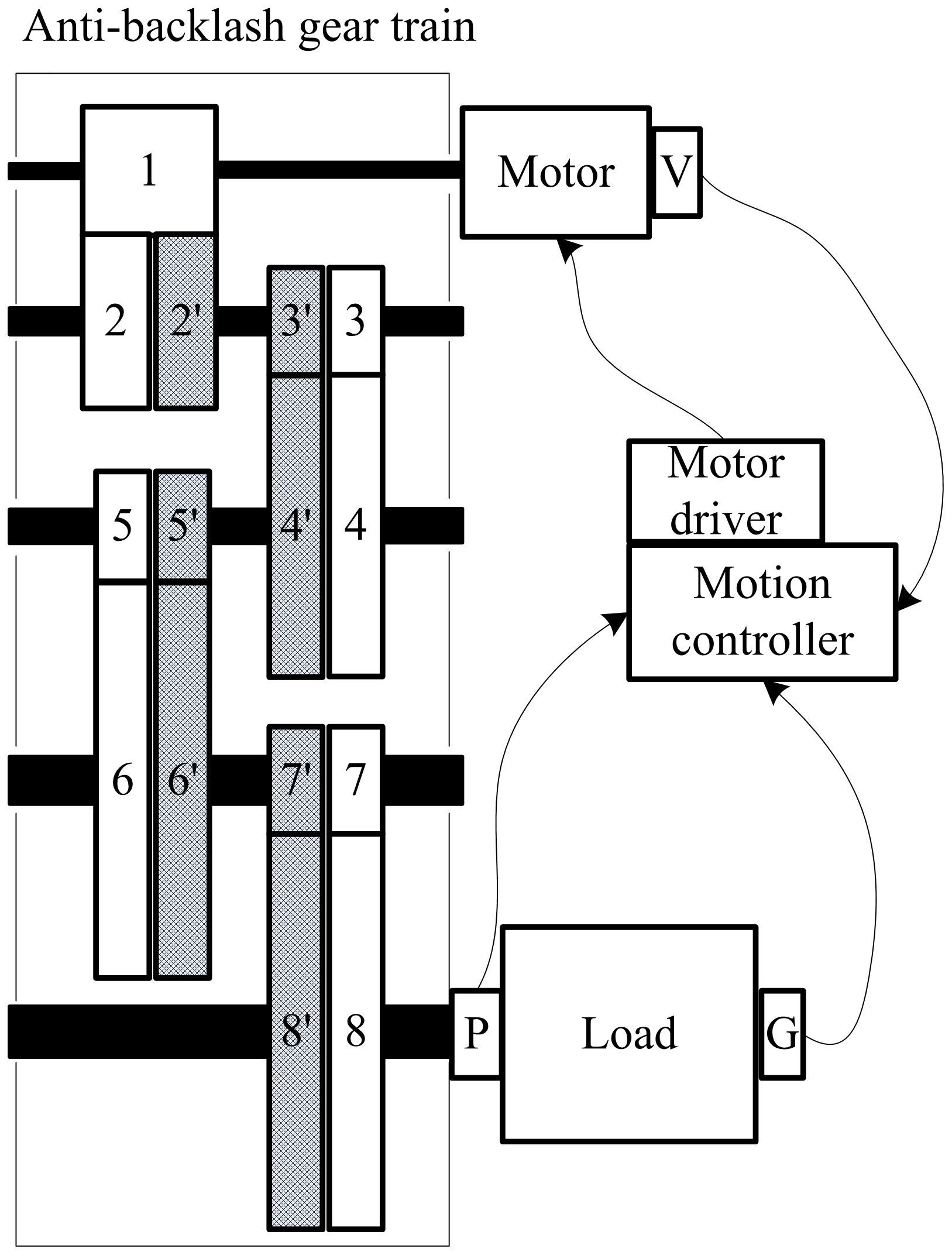
Figure 1Schematic of the anti-backlash geared servo system. V is a tachometer, P is a potentiometer as load position sensor, and G is a gyroscope.
In Fig. 1, the anti-backlash gear train is mainly composed of driving gear (1), main gears (2, 3, 4, 5, 6, 7, 8), freewheel gears (2′, 3′, 4′, 5′, 6′, 7′, 8′), torsional spring and bearing. The driving gear is connected to the motor. Following the motor rotation, the main gears are fixed on the shafts, and the freewheel gears are nested on the shafts, which rotate around the shafts. One of the torsional spring butts is fixed on the last stage main gear (8). Another one is fixed on the last stage freewheel gear (8′). A certain preload is applied on the torsional spring to guarantee the main and freewheel gears contact with the positive or negative teeth surface of the driving gear, respectively, so as to eliminate the backlash. In the anti-backlash geared servo system, the elasticity of transmission chain can not be neglected, which makes the machine resonance close to the bandwidth of the gyroscope closed loop. Therefore, the key factors affecting the frequency response characteristics of system need to be analyzed, which are helpful to the design, assembly and application of the anti-backlash gear train.
2.2 Model of the anti-backlash geared servo system
In the multistage anti-backlash gear train, the transmission components can be treated as a single, composite, equivalent torsional spring that interconnects with the motor and load, which is shown in Fig. 2.
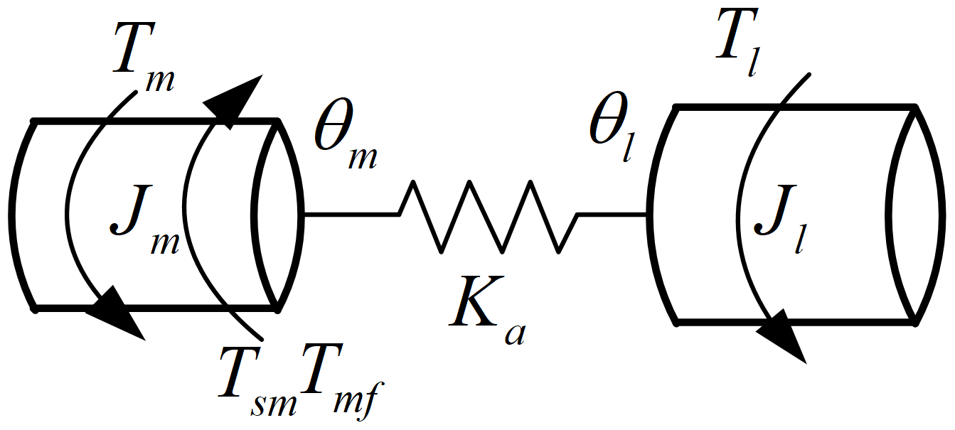
Where Jm is the equivalent moment of inertia on the motor shaft, it mainly contains the moment of inertia of motor rotor, equivalent moment of inertia of each stage main and freewheel gears and shafts (not containing the last stage); θm is the angular displacement of the motor; Tm is the output torque of the motor, its direction is the left arrow in the figure; Tmf is the total equivalent friction torque; Tsm is the torsional torque applied on the motor by the transmission train, Tmf and Tsm direction is the arrow in the middle in the figure, which is the reverse direction to the Tm direction; Tl is the driving torque of the last stage shaft on the load; its direction is the right arrow in the figure, the same direction with the Tm direction; Jl is the equivalent moment of inertia of load; it mainly contains the moment of inertia of the last stage main and freewheel gears, the shaft and the load; θl is the angular displacement of the load; Ka is the equivalent stiffness of the anti-backlash gear train.
The output torque of the motor is controlled. Namely, the motor driver is operated in the current closed-loop mode, and the controller of current loop is a proportional plus integral (PI). The composite model of motor driver and motor can be written as
where Ua is the input voltage of the motor; Ra is the resistance of the motor armature; La is the inductance of the motor armature; Ia is the current of the motor; Ea is the back electromotive force (EMF); Ke is the back electromotive force coefficient; Kt is the torque coefficient; Kp is the proportional gain of the current loop controller; KI is the integral gain of the current loop controller; Kpwm is the motor driver gain; Ic is the reference signal of the current loop.
In the spur-gear train, if the backlash is not considered, the transmission torque can be calculated by
where Ni is the ratio of each stage gear train, Tl is the torque transmitted to the load from the last stage transmission shaft, Ka is the comprehensive stiffness of transmission train, and n is the stages number of the gear train.
However, the backlash can not be neglected in the system. If the transmission angle error Δθ is small enough, the motor and load does not contact in the backlash area. The transmission torque of gear train can be rewritten as (Nordin and Gutman, 2002)
where b is half of total backlash of gear train.
Compared with the general spur-gear train, the motor and load always contact in the anti-backlash gear train because of the preload torsional spring. The transmission torque is not zero in the backlash area, and the equivalent stiffness of the backlash area should be considered, which is different with the spur-gear train. Assuming that the equivalent stiffness of main gear train is Keq1, the equivalent stiffness of freewheel gear train is Keq2, and the stiffness of torsional spring is Kx. Then, the stiffness model of anti-backlash gear train can be shown in Fig. 3. The arrow in the middle is the direction of Tm, and the right arrow is the direction of Tl.
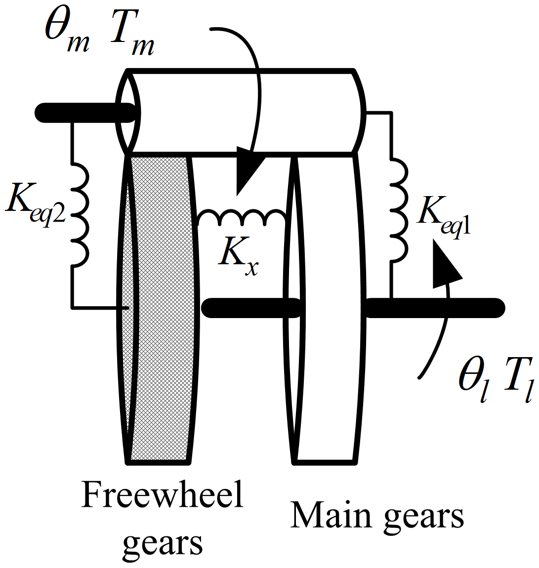
There are two states in the anti-backlash gear motion process. One is the motion in the backlash area. The main gear train does not transfer the torque directly. The torque is transferred through the freewheel gear train and the torsional spring. The equivalent stiffness of the anti-backlash gear train is the series of Keq2 and Kx, which can be calculated by
Another motion process is not in the backlash area. The main gear train, freewheel gear train and torsional spring all take part in the torque transmission. The equivalent stiffness contains two parts: one part is the series of Keq2 and Kx; another part is Keq1. The formula can be written as
In the spur-gear train, with the existence of backlash, the relation between the transmission angle error and transmission torque is described in Fig. 4a. However, in the anti-backlash gear train, the relation between the transmission angle error and transmission torque can be described in Fig. 4b, as the equivalent stiffness is not zero in the backlash area.
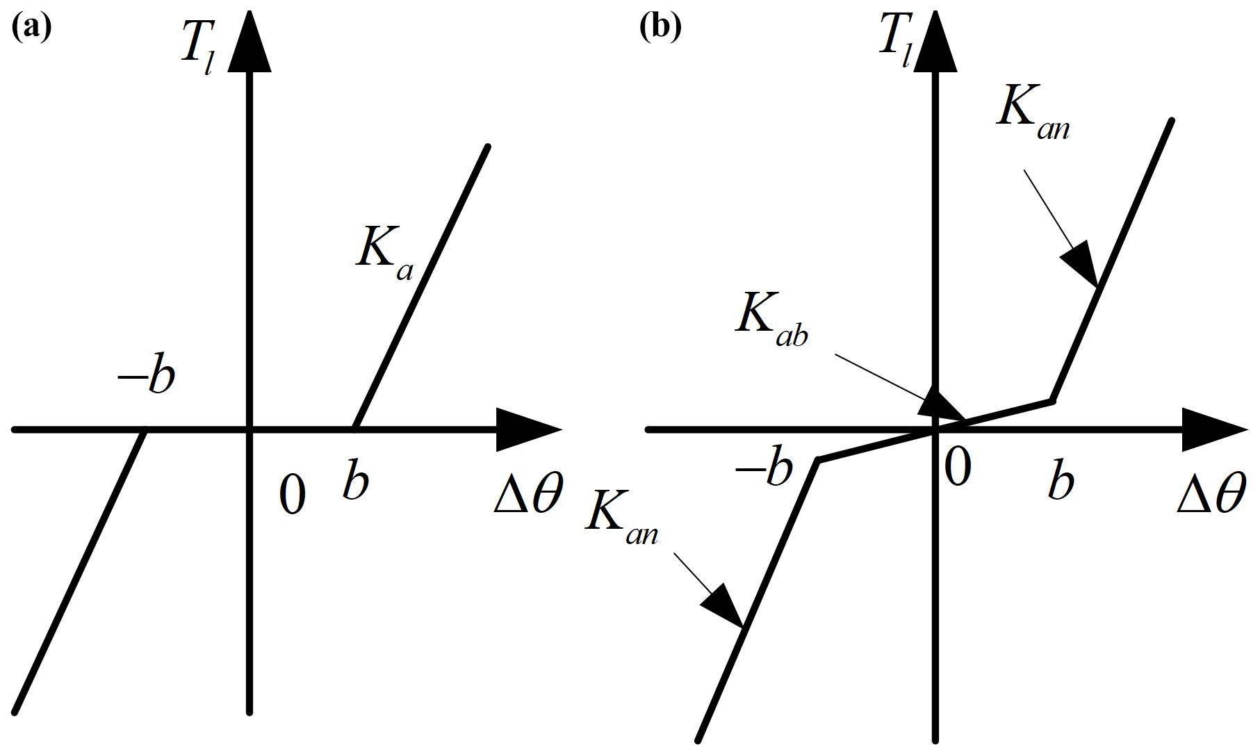
Figure 4Stiffness to transmission angle error. (a) Gear with backlash. (b) Anti-backlash gear.
Compared with the general spur-gear train, the equivalent stiffness is enhanced by using the anti-backlash gear, especially when the transmission angle error is larger than the backlash. Based on Fig. 4b, compared with Eq. (3a), the equivalent stiffness is not zero, but the combination of the freewheel gear train and the torsional spring stiffness when the motion is in the backlash area (|Δθ|≤b), and if the motion is outside the backlash, the main gear train, freewheel gear train and torsional spring will have a comprehensive effect on transferring torque, so the transmission torque of the anti-backlash gear train can be written as follows:
According to the two-inertia modeling method, the differential equations of the anti-backlash gear train can be written as
Based on above analysis, the differential equations of the anti-backlash geared servo system can be obtained by combining Eqs. (1) and (4)–(7). Using the Laplace transform, the block diagram of model of the anti-backlash geared servo system in s domain is shown in Fig. 5.
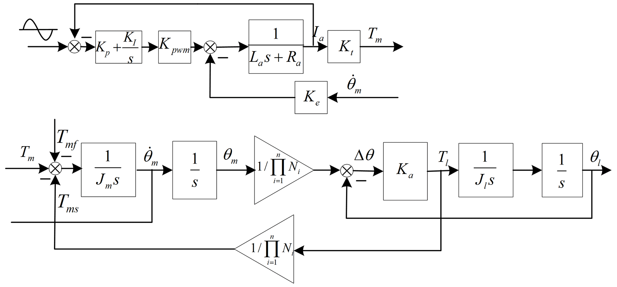
The model has been established, but the key parameters of the model are unknown. At the mechanism design stage, the parameters can only be obtained through theoretical analysis. The formulas of Jm, Jl, Keq1, Keq2 and Kx will be deduced.
2.3 Formulas of key parameters
In the anti-backlash geared servo system model, the parameter values of motor, motor driver and bearing friction can be obtained from their handbooks. However, for the anti-backlash gear train, researchers only know the size and material of gears and springs. The equivalent moment of inertia and stiffness can not be obtained directly. Without considering the backlash, the main gear train and the freewheel gear train may be considered as a spur-gear train. The calculation methods of equivalent stiffness of the spur-gear train can be used (Baek et al., 2003b). The anti-backlash gear train is composed of the main gear train and the freewheel gear train, which is connected together by a torsional spring, as shown in Fig. 6.
In the two-inertia system, the motor is one mass, and the load is another one. The total mass of the system is focused on the motor and load. The equivalent moment of inertia of the motor can be calculated by
where J0 is the total moment of inertia of the motor rotor, driving gear and shaft; JFi is the total moment of inertia of the gear and shaft of each stage main gear train (the last stage is not contained ); JHi is the total moment of inertia of the gear and shaft of each stage freewheel gear train (the last stage is not contained).
Then, the equivalent moment of inertia of load can be calculated by
where Jl0 is the moment of inertia of pure load; JF4 is the total moment of inertia of the gear and shaft of last stage main gear; JH4 is the total moment of inertia of the gear and shaft of last stage freewheel gear.
From Fig. 6, the Keq1 can be calculated with the series of each stage main gear stiffness KFi; Keq2 can be calculated with the series of each stage freewheel gear stiffness KHi. The KFi and KHi can be calculated by
where KFgi is the mesh stiffness of each stage main-driven gear and KHgi is the mesh stiffness of each stage freewheel-driven gear. They can be calculated by (Zhou et al., 2009)
where E is Young's modulus of the gears; dXgi is the pitch circle diameter of each gear; Wi is the width of each gear; λ is the pressure angle of the gears.
KFsi is the stiffness of each stage main gear shaft, and KHsi is the stiffness of each stage freewheel gear shaft. They can be calculated by (Zhou et al., 2009)
where G is the shear modulus of the gear shafts; dXsi is the diameter of each gear shaft; LXsi is the length of each gear shaft. Based on the relations between the input and output torque of anti-backlash gear train, formulas Keq1 and Keq2 can be written as
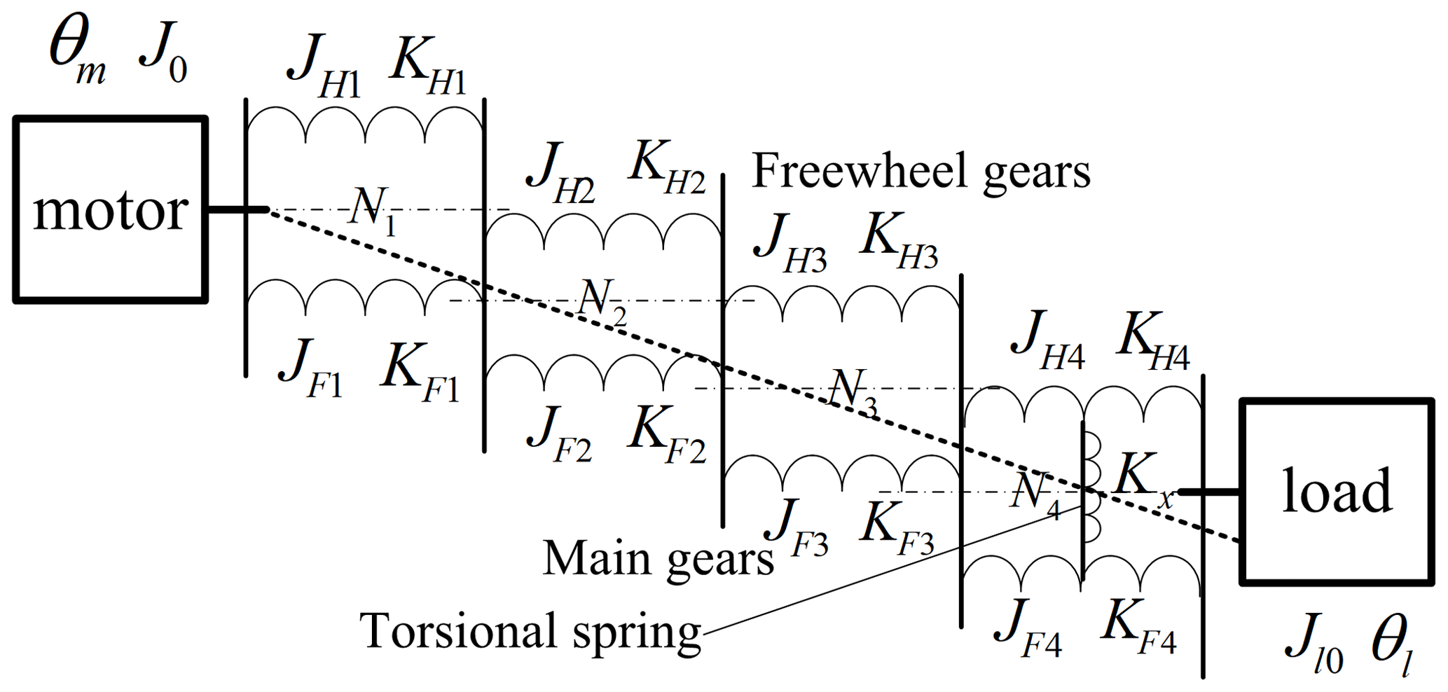
From Fig. 6, the freewheel gear train is connected to the main gear train through a torsional spring. The torque is transferred by both the freewheel gear train and the torsional spring in the backlash area, so the stiffness of torsional spring needs to be considered in the model. The structure of torsional spring is shown in Fig. 7, which is an arc spring, with a rectangular section and the same material as the gears.
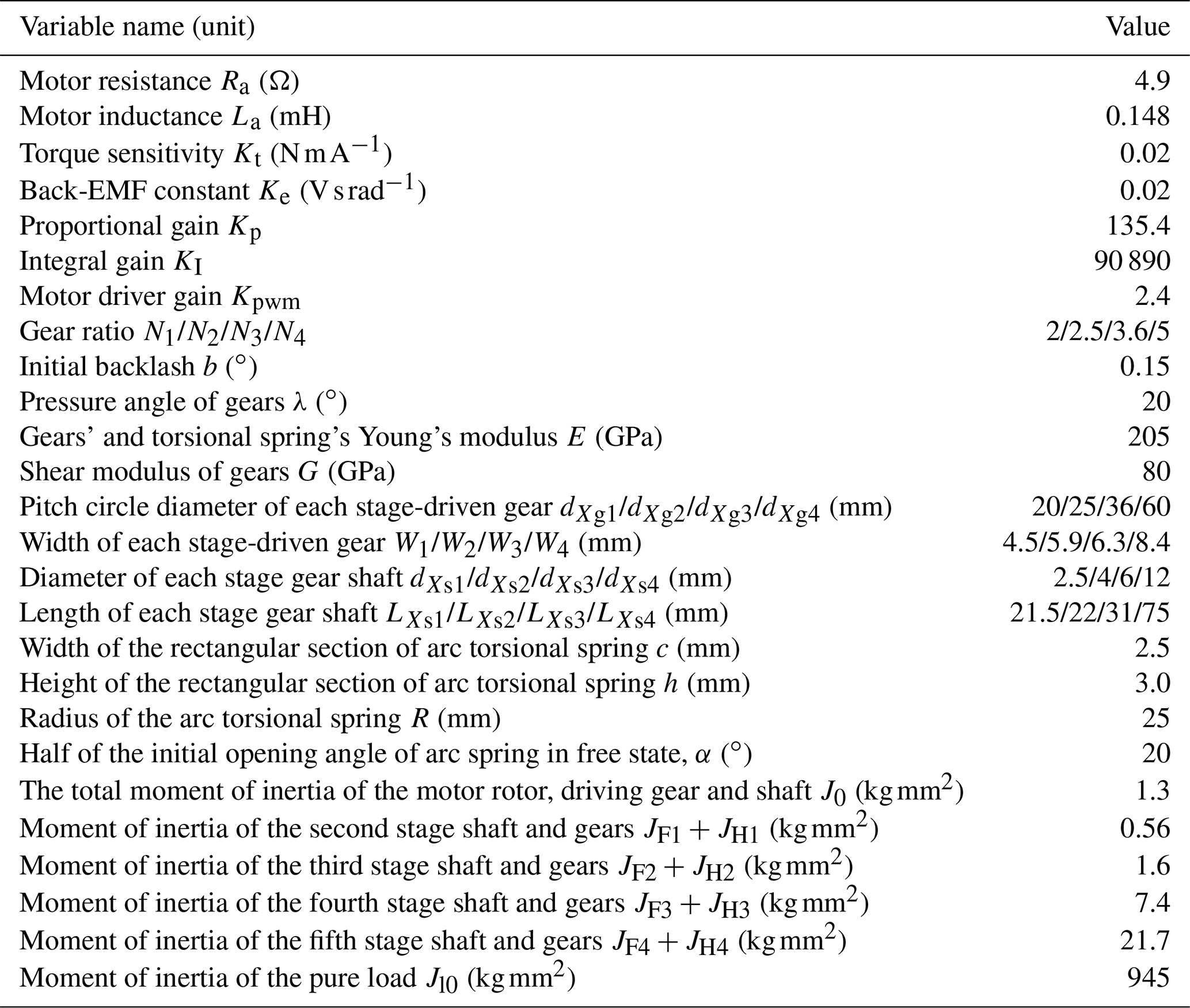
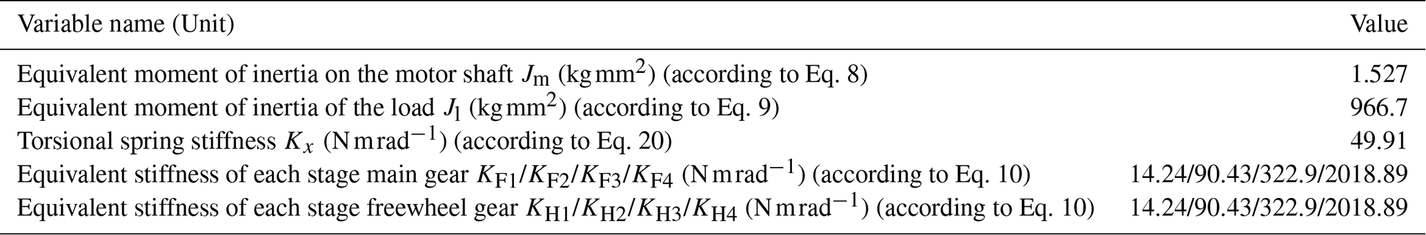
Table 1Parameters values of the anti-backlash geared servo system.
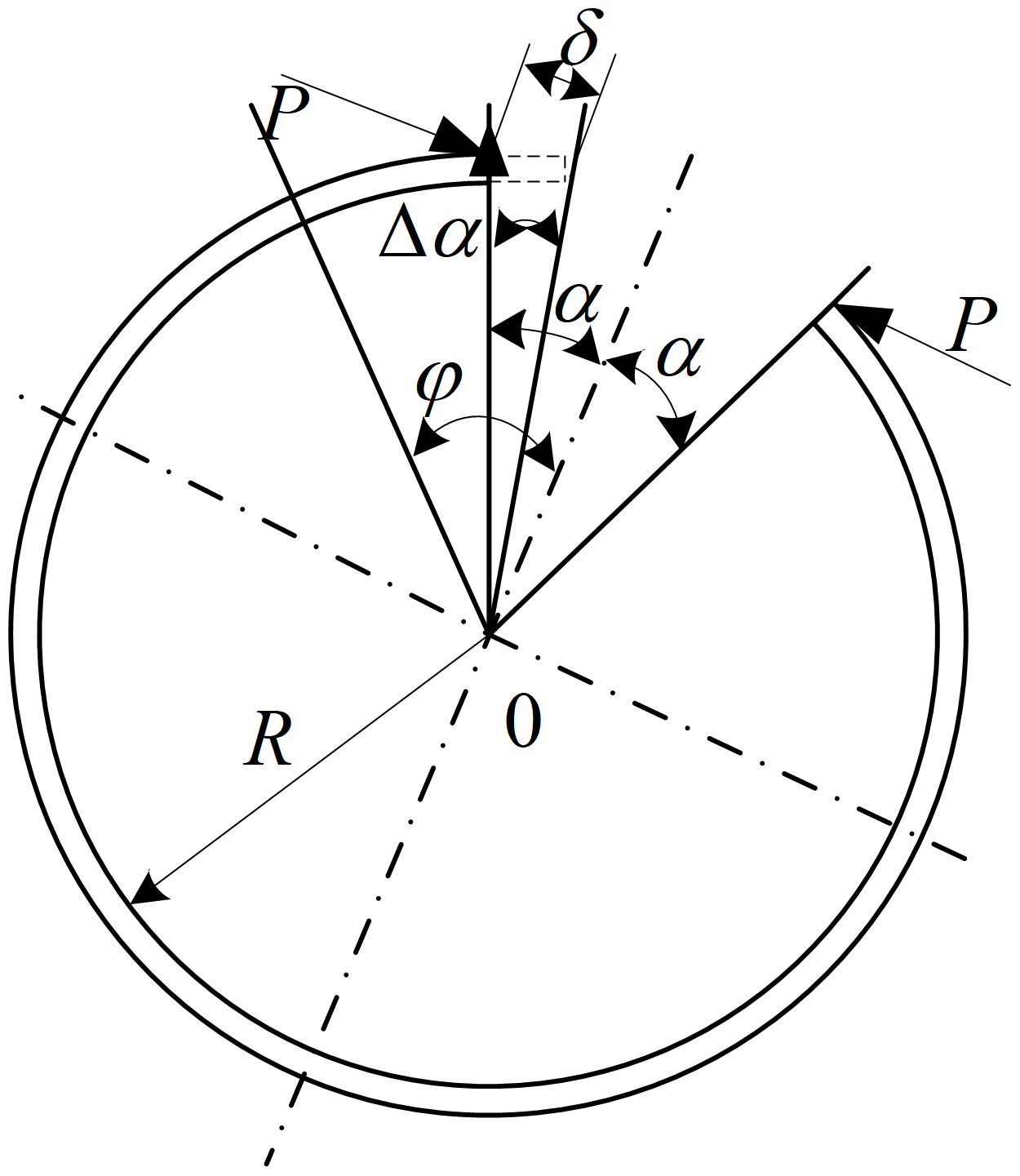
Assuming that a force P is applied perpendicular to the center line of the arc spring vertically, the deformation is δ, according to the principle of virtual work, the δ can be written as
where α is half of the initial opening angle of arc spring in free state; R is the radius of the arc spring; I is the moment of inertia of the spring's rectangular section. , and . Substituting these equations into Eq. (15), δ can be rewritten as
If we let , then Eq. (16) can be rewritten as
where I can be calculated by
where c is the width of the arc spring's rectangular section; h is the height of the arc spring's rectangular section.
Equation (17) can be rewritten as
When force P is applied on the spring, the variation value of the opening angle is Δα. If Δα is small enough, , then δ=RΔα. Substituting this equation into Eq. (19), the stiffness of the torsional spring can be written as
where T the torque generated by force P around the center of the arc spring.
Based on the above analysis, the values of key parameters of the system – Jm, Jl, Keq1, Keq2 and Kx – are obtained through Eqs. (8), (9), (13), (14) and (20). Now, with these parameters and the block diagram in Fig. 5, the influences of key parameters on the frequency response characteristics of the anti-backlash geared servo system will be simulated and analyzed.
The simulation model of the anti-backlash geared servo system is built in Fig. 5. The values of basic parameters in the model are shown in Table 1, and parameter values of computed variables are shown in Table 2. As the input of system, the excitation signal is a chirp sinusoidal signal; the frequency ranges from 1 to 300 Hz; the response signal is the angular velocity of the motor, which is the output of system. The sampling time interval is 0.2 ms. The bode diagram of input/output can be obtained. The influences of backlash, torsional spring stiffness, load, gear mesh stiffness and gear shaft stiffness variation on the frequency response characteristics of system can be obtained.
3.1 The effect of backlash
In the anti-backlash geared servo system, if changing the magnitude of backlash only and other model parameters shown in Tables 1 and 2, the backlash ranges from 0.01 to 0.5∘. The influence of backlash variation on the frequency response characteristics of system is shown in Fig. 8. The backlash of the anti-backlash gear train is the total backlash before the torsional spring installation, which can be adjusted by the center distance between the driving and driven gear. When the torsional spring is fixed on the last stage main gear and freewheel gear, the space backlash of anti-backlash gear train is very small but not completely eliminated.
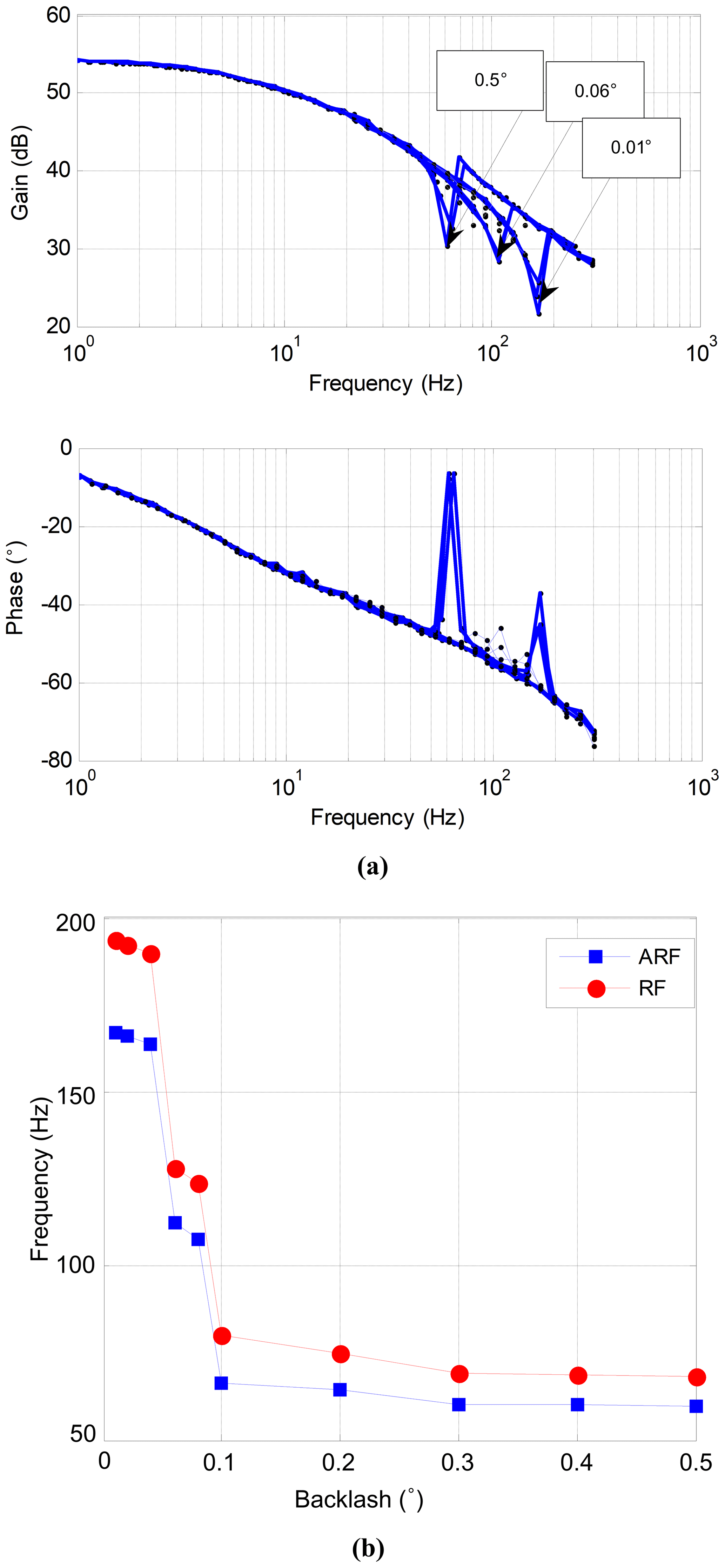
Figure 8Influence of backlash variation on the frequency response characteristics of system. (a) Bode diagram dependent on backlash variation. (b) Anti-resonance and resonance frequencies dependent on backlash variation.
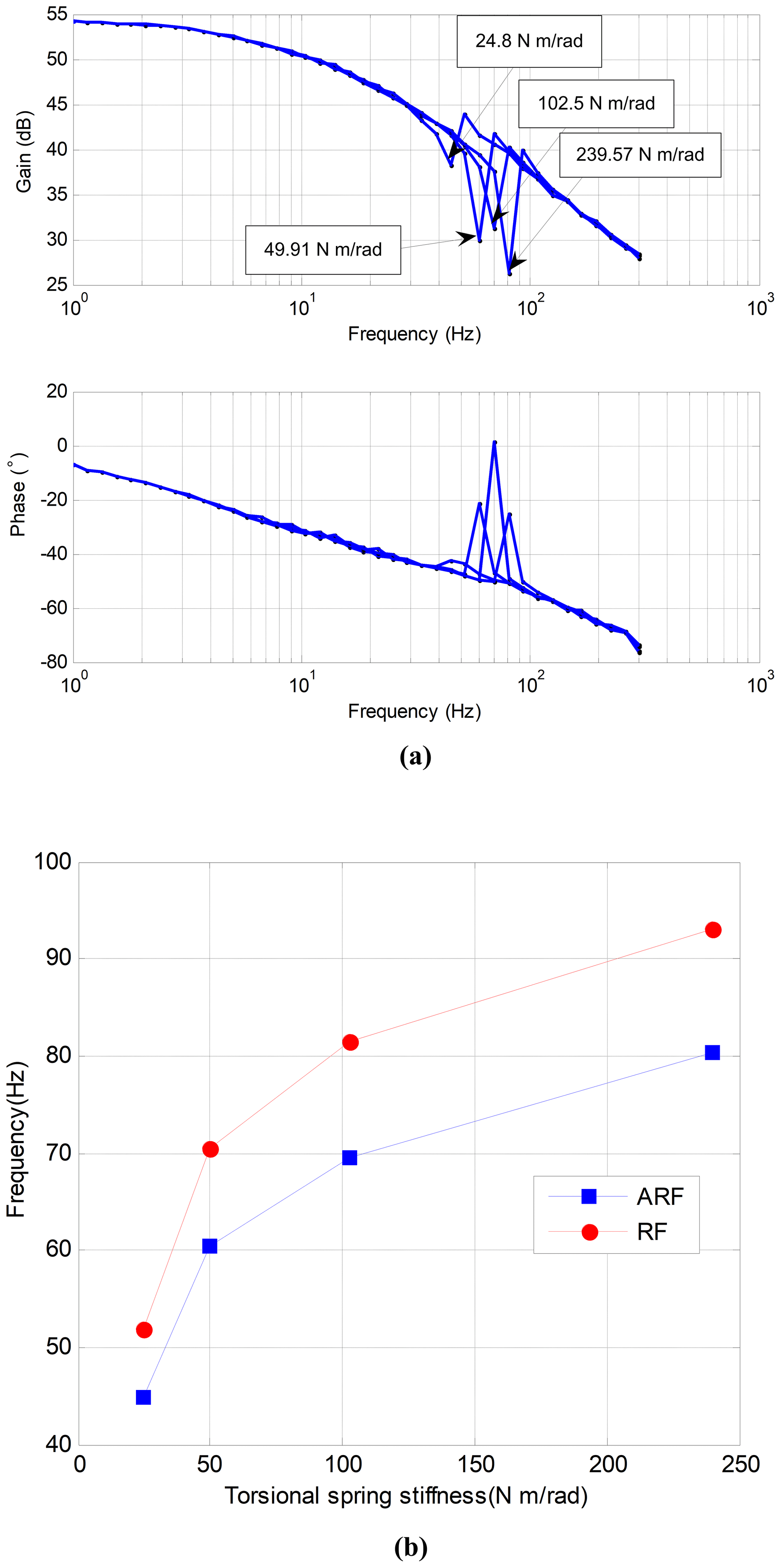
Figure 9Influence of torsional spring stiffness variation on the frequency response characteristics of system. (a) Bode diagram dependent on torsional spring stiffness variation. (b) Anti-resonance and resonance frequencies dependent on torsional spring stiffness variation.
The anti-resonance and resonance frequencies decrease with the increase of backlash. When the backlash ranges from 0.01 to 0.5∘, the anti-resonance frequency ranges from 170 to 60 Hz, and the resonance frequency ranges from 190 to 70 Hz. The results show that the anti-resonance and resonance frequencies can be adjusted at a large range by changing the magnitude of backlash. However, in the practical system, if there is no center distance adjusting mechanism, the total backlash is decided by the assembly technology. It is difficult to control the magnitude of backlash in the assembly process. Therefore, the method to improve the frequency response characteristics of system by adjusting the total backlash is to design the center distance adjusting mechanism.
3.2 The effect of torsional spring stiffness
In the anti-backlash geared servo system, only changing the stiffness of the torsional spring, the influence of torsional spring stiffness variation on the frequency response characteristics of system is analyzed. Due to the size restriction of the last stage main and freewheel gears, the radius of torsional spring can not be changed. Only the width or height of rectangular section can be adjusted. In this paper, four kinds of torsional spring are chosen. Their stiffnesses are [24.80, 49.91, 102.50, 239.57] N m rad−1, respectively. The result is shown in Fig. 9.
In Fig. 9, the anti-resonance and resonance frequencies increase with the increase of stiffness of the torsional spring. When the stiffness is [24.80, 49.91, 102.50, 239.57] N m rad−1, the anti-resonance frequency is [44.8, 60.4, 69.5, 80.4] Hz, and the resonance frequency is [51.8, 70.5, 81.4, 93.1] Hz. However, the frequency increment is restricted by the requirements of installation space and elastic force of the anti-backlash gear train. Compared with the backlash, the method to improve the frequency response characteristics of system by adjusting the size of torsional spring is relatively easy in engineering applications. The result is validated in Sect. 4.
3.3 The effect of load
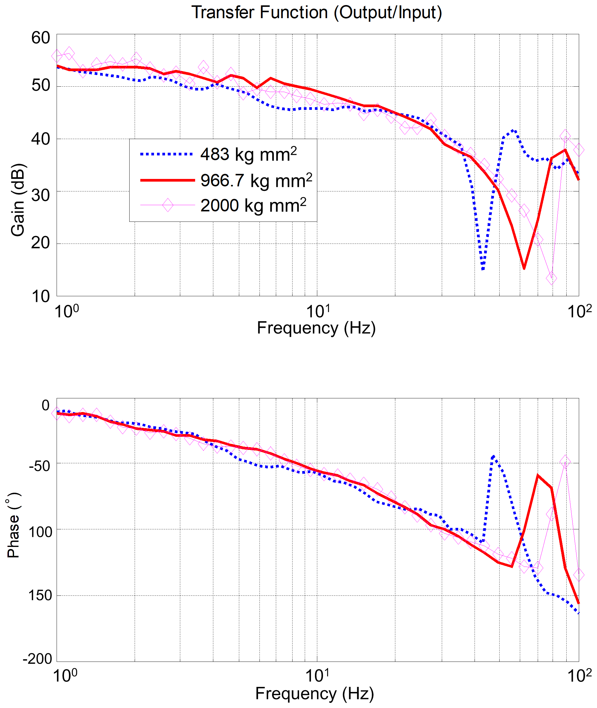
The anti-backlash gear train is applied in the inertially stabilized platform, which should remain the same control precision in different load conditions. While the resonance frequency of system is one of the main factors which influence the control precision, the influence of load variation on the frequency response characteristics of system is analyzed. In the simulation model, only changing the load moment of inertia, the load moment of inertia ranging from 483 to 2000 kg mm2. The result is shown in Fig. 10.
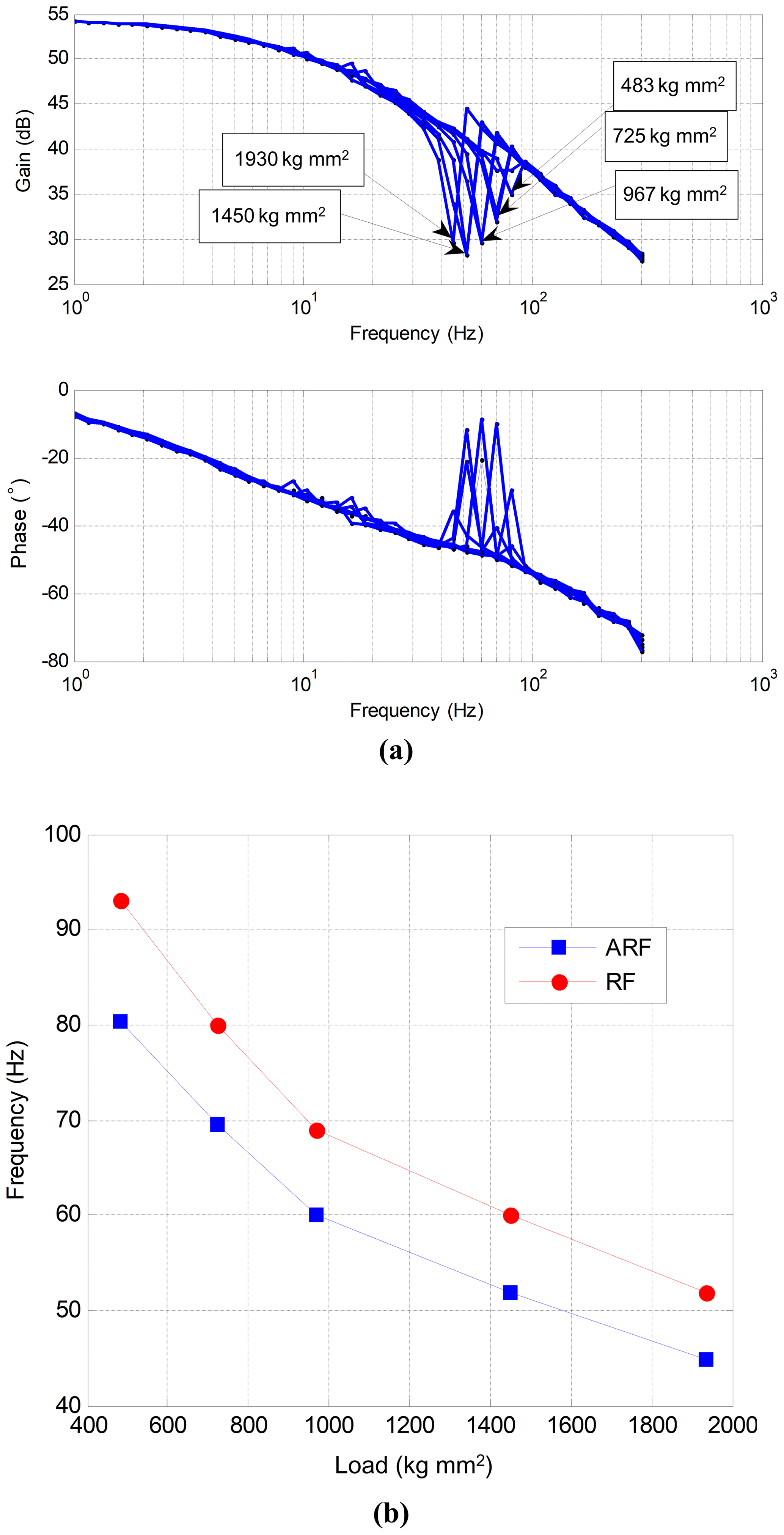
Figure 10Influence of load variation on the frequency response characteristics of system. (a) Bode diagram dependent on load variation. (b) Anti-resonance and resonance frequencies dependent on load variation.
From Fig. 10, the resonance and anti-resonance frequencies decrease with the increase of load moment of inertia. When the moment of inertia ranges from 483 to 2000 kg mm2, the anti-resonance frequency ranges from 82 to 44 Hz, and the resonance frequency ranges from 92 to 52 Hz, so the method to improve the frequency response characteristics of system is the lightweight design of load. However, the lightweight design may decrease the stiffness of the load, which will affect the resonance frequencies too. Thus, there should be a compromise between the lightweight design and stiffness decreasing of the load in the mechanical design.
3.4 The effect of gear and shaft stiffness
In the anti-backlash gear train, the size and material of each stage freewheel gear are the same as the main gear of the same stage, so KHi is equal to KFi. The equivalent stiffness of each stage main or freewheel gear is decided by the mesh stiffness of gear pair and the stiffness of gear shaft. However, the mesh stiffness is decided by the width and pitch circle diameter of the driven gear, and the stiffness of gear shaft is decided by the diameter and length of the shaft, so the KHi and the KFi can be changed by adjusting the size of driven gear or gear shaft. In the simulation model, assuming that the variation ranges of KFi and KHi are from 0.5 to 2 times initial value, namely , , the influences of KFi and KHi variation on the frequency response characteristics of system are shown in Fig. 11.
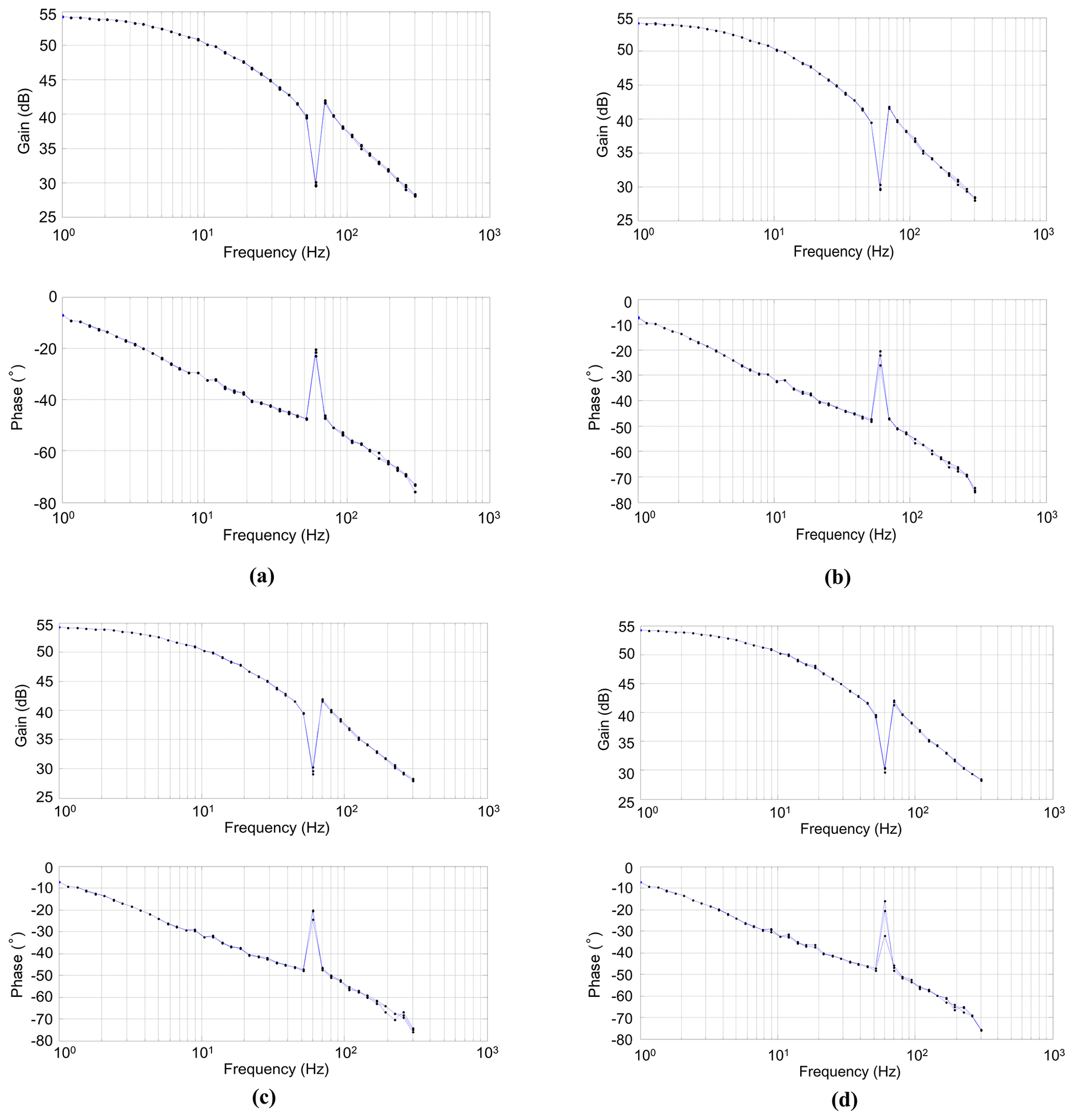
Figure 11Bode diagrams of anti-backlash geared servo system with the gears and shafts stiffness variation. (a) KF1 and KH1. (b) KF2 and KH2. (c) KF3 and KH3. (d) KF4 and KH4.
From Fig. 11, when the KFi and KHi change, the anti-resonance and resonance frequencies remain the same, so it is difficult to improve the frequency response characteristics of system by adjusting the size and material of main and freewheel gears. The simulation results also show that the farther away the gear is from the load, the less the influence on the frequency response characteristics of system caused by gear and shaft stiffness variation. The stiffnesses of the last stage main and freewheel gear have the greatest influence. So strengthening the stiffness of the last stage main and freewheel gear should be considered in the design process. However, when the mechanism of anti-backlash gear train has been produced and assembled completely, changing the size of main and freewheel gears becomes difficult, so the simulation results will not be verified in the next experiments.
The experimental setup of anti-backlash geared servo system is shown in Fig. 12, which is composed of an anti-backlash gear mechanism, motor driver (Maxon-ADS50V/5A), dSPACE1103 hardware-in-loop simulation system and a computer. The tachometer is used to measure the angular velocity of the motor, and the sensitivity is 0.1 . The motor driver works at the current mode; its maximum continuous current is 5 A; the input signal ranges from −10 to +10 V; the current sensitivity is 0.8 V A−1. dSPACE1103 provides AD and DA interface; the resolution is 14 bit; the interface modules are embedded in MATLAB/Simulink; the voltage of tachometer can be sampled and motor driver control signal can be generated; the bode diagram of output/input can be plotted in MATLAB. The simulation results of Sects. 3.1 and 3.4 will not be verified, because it is not easy to adjust the backlash, gear mesh stiffness and gear shaft stiffness. The simulation results of Sects. 3.2 and 3.3 will be verified in this experimental setup.
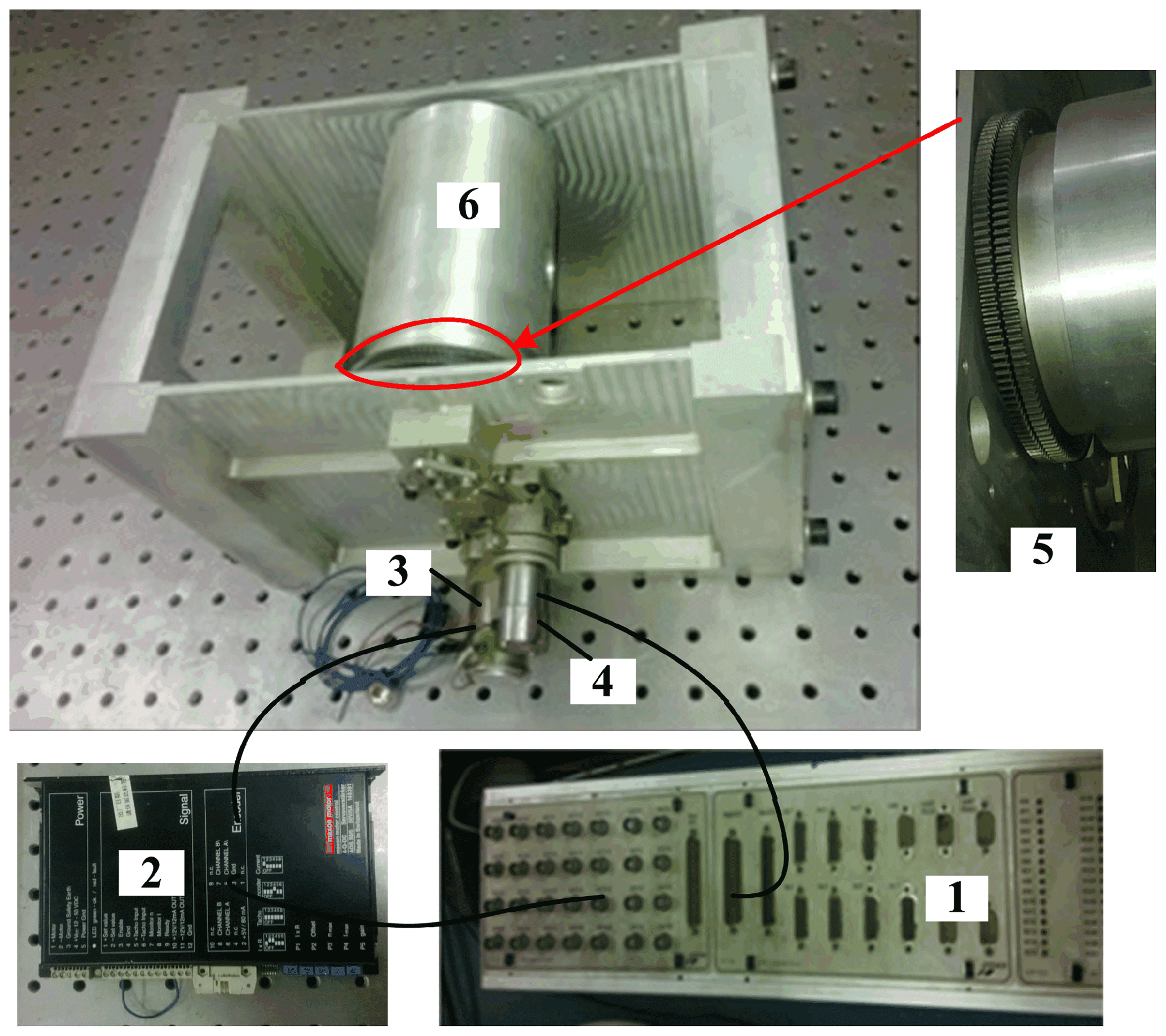
Figure 12Experimental setup of the anti-backlash geared servo system: (1) dSPACE1103, (2) motor driver, (3) motor, (4) tachometer and (5) anti-backlash gear train, six-load.
The initial state of the experimental setup containing the magnitude of backlash is approximately 0.15∘; the stiffness of torsional spring is 49.91 N m rad−1; the moment of inertia of load is 966.7 kg mm2; the size and material of main and freewheel gears are designed according to the specific project. First, the frequency response characteristics of experimental setup are tested in the initial state. The resonance and anti-resonance frequencies are obtained from the bode diagram. Then, three kinds of torsional spring are used to replace the initial one. They have different rectangular sections; the calculated values of stiffness are [24.80, 102.50, 239.57] N m rad−1. The frequency response characteristics of servo system with these torsional springs are tested, respectively. The results are shown in Fig. 13. Finally, the stiffness of torsional spring remains 49.91 N m rad−1. Only changing the moment of inertia of load, three kinds of load are used to replace the initial one. The moments of inertia values are [483, 966.7, 2000] kg mm2. The frequency response characteristics of them are tested, respectively, and the results are shown in Fig. 14.
Table 3Comparative analysis between the simulation and experiment results.
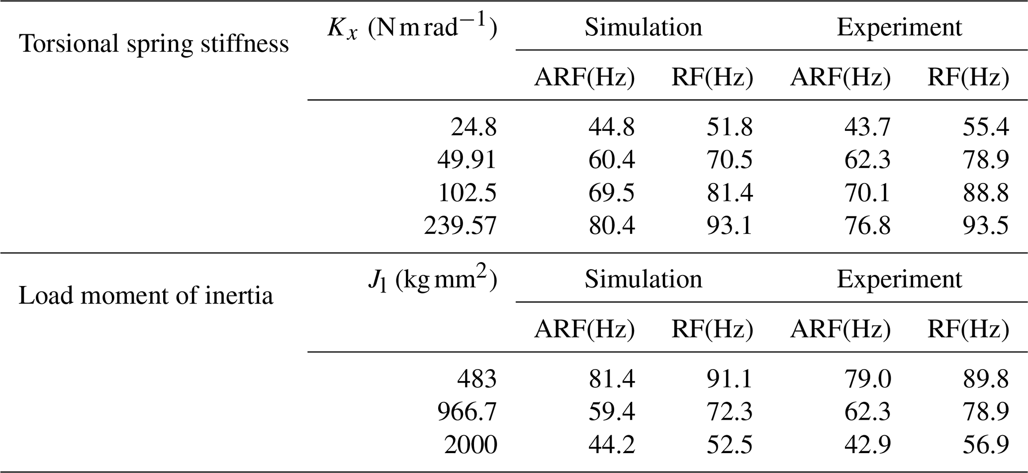
From Figs. 13 and 14, the resonance and anti-resonance frequencies of system increase with the increase of torsional spring stiffness and decrease with the increase of load moment of inertia. Compared with the experiment results, the maximum error of simulation results is less than 10 Hz, which is shown in Table 3. These results show that the model of anti-backlash geared servo system is reasonable; the simulation results of Sects. 3.2 and 3.3 are correct, and the simulation results of Sects. 3.1 and 3.4 are a credible prediction. The errors of simulation analysis are caused by the model parameter difference compared with the experimental setup system. When the mechanism of anti-backlash gear train is assembled, the parameters of model can be obtained through the experiment identification, and then the experiment results may stay more consistent with simulation results.
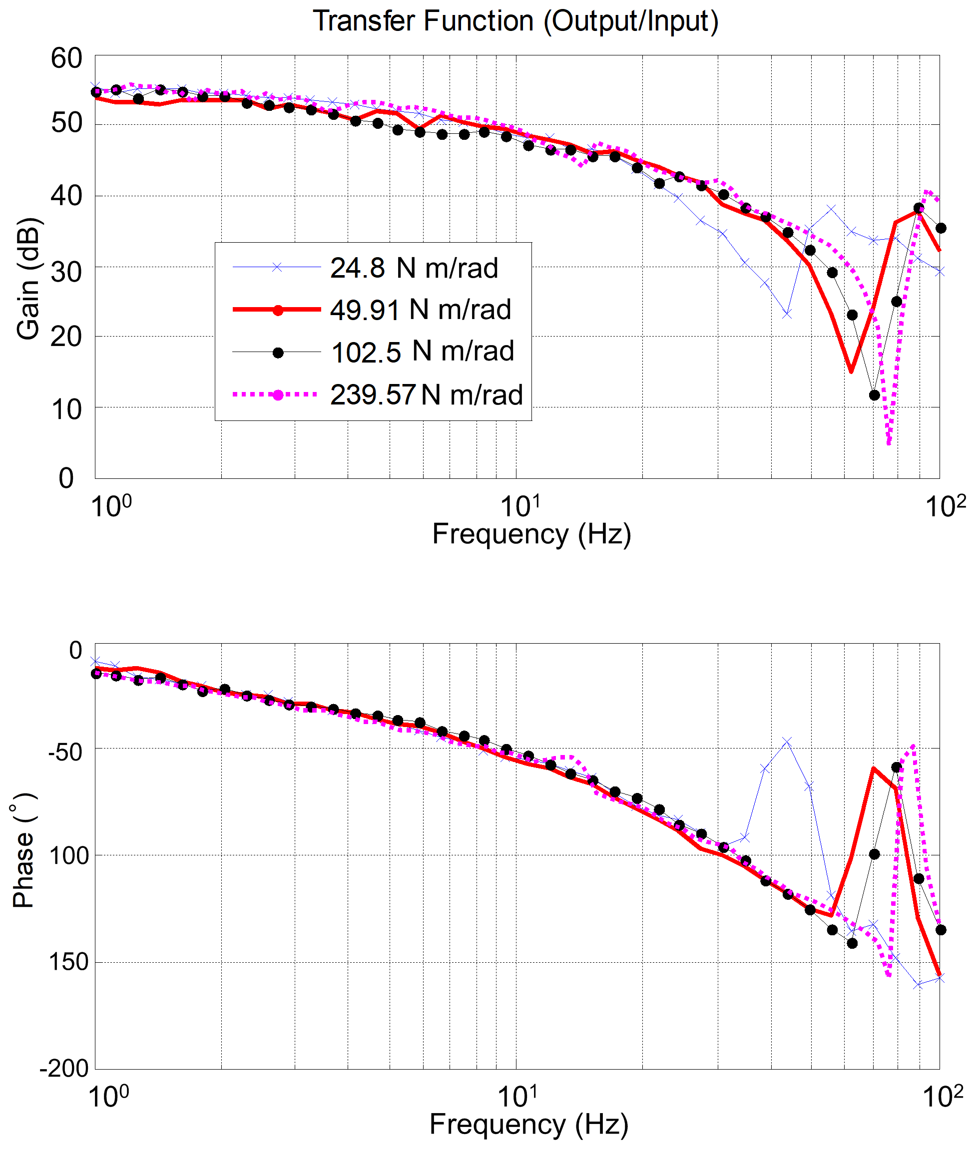
Figure 13Bode diagram of the experimental setup with different torsional spring stiffnesses.
The total backlash, torsional spring stiffness and load moment of inertia are the main factors that influence the frequency response characteristics of the anti-backlash geared servo system. The resonance and anti-resonance frequencies increase with the decrease of the total backlash and the load moment of inertia and increase with the increase of the torsional spring stiffness.
The simulation results show that when the total backlash ranges from 0.01 to 0.5∘, the anti-resonance frequency ranges from 170 to 60 Hz, and the resonance frequency ranges from 190 to 70 Hz; when the stiffness of torsional spring is [24.80, 49.91, 102.50, 239.57] N m rad−1, the anti-resonance frequency is [44.8, 60.4, 69.5, 80.4] Hz, and the resonance frequency is [51.8, 70.5, 81.4, 93.1] Hz; when the load moment of inertia ranges from 483 to 2000 kg mm2, the anti-resonance frequency ranges from 82 to 44 Hz, and the resonance frequency ranges from 92 to 52 Hz; when the variation ranges of gear mesh stiffness and gear shaft stiffness are from 0.5 to 2 times initial value, the anti-resonance and resonance frequencies remain the same. The experiment results show that the maximum error of simulation results is less than 10 Hz. The model of anti-backlash geared servo system is reasonable. The simulation results of Sects. 3.2 and 3.3 are correct, and the simulation results of Sects. 3.1 and 3.4 are a credible prediction.
From the mechanical parameter point of view, increasing the stiffness of torsional spring can improve the frequency response characteristics of system. This target is easy to realize by changing the width or height parameters of rectangular section of the torsional spring. Reducing the total backlash of anti-backlash gear train is another method of system improvement. The magnitude of backlash is influenced by the manufacture and assembly technology. From the mechanical design aspect, designing the center distance adjusting mechanism can decrease the initial total backlash, and the load lightweight design can also improve the frequency response characteristics of system, but the stiffness of the load should be considered simultaneously. These measures will be applied in our future work.
All data generated or analyzed during this study are included in this published article.
LZ and HL designed the methodology, created the model, simulated the model and designed the experimental setup of servo system. DF provided the ideas, financial support and supervised the research activity planning and execution. SF designed the experimental software and collected the experimental data. JZ designed the mechanical structure of anti-backlash geared setup and the arc springs. LZ designed the experiments and carried them out. LZ and HL prepared the manuscript with contributions from all co-authors.
The authors declare that they have no conflict of interest.
The authors would like to express their thanks to the supporting agencies.
This research has been supported by the National Key R&D Program of China (grant no. 2019YFB2004700) and the Preliminary Research Project of National University of Defense Technology (grant no. ZN2019-7).
This paper was edited by Dario Richiedei and reviewed by two anonymous referees.
Allan, P. M. and Levy, N. M.: The determination of minimum pre-load torque for antibacklash gears in a positional servomechanism, IEEE Trans. Ind. Electron., 27, 26–29, https://doi.org/10.1109/TIECI.1980.351657, 1980.
Asada, H., Youcef-Toumi, K., and Koren, Y.: Direct-Drive robots, theory and practice, J. Dyn. Syst. Meas. Control, 111, 119–120, https://doi.org/10.1115/1.3153012, 1989.
Baek, J. H., Kwak, Y. K., and Kim, S. H.: Backlash estimation of a seeker gimbal with two-stage gear reducers, J. Adv. Manuf. Technol., 21, 604–611, https://doi.org/10.1007/s00170-002-1378-z, 2003a.
Baek, J. H., Kwak, Y. K., and Kim, S. H.: Analysis on the influence of backlash and motor input voltage in geared servo system, 11th IEEE Mediterr. Conf. Control and Automat., Rhodes, Greece, 18–20 June 2003, T1-010, 2003b.
Bahn, W., Kima, T. I., Li, S. H., and Cho, D. I.: Resonant frequency estimation for adaptive notch filters in industrial servo systems, Mechatronics, 41, 45–57, https://doi.org/10.1016/j.mechatronics.2016.11.004, 2016.
Chung, J. W., Park, I. W., and Oh, J. H.: On the design and development of a quadruped robot platform, Adv. Robot., 24, 277–298, https://doi.org/10.1163/016918609X12586214966992, 2010.
Dwivedula, R. V. and Pagilla, P. R.: Effect of Compliance and Backlash on the Output Speed of a Mechanical Transmission System, J. Dyn. Syst. Meas. Control, 134, 031010, https://doi.org/10.1115/1.4005493, 2012.
George, E. and Gao, Z. Q.: Cures for low-frequency mechanical resonance in industrial servo systems, IEEE 36th IAS Annu. Meet.Chicago, USA, 30 September–4 October 2001, 252–258, https://doi.org/10.1109/IAS.2001.955419, 2001.
George, W. Y.: Compensating structural dynamics for Servo Driven Industrial Machines with acceleration feedback, IEEE 39th IAS Annu. Meet., Seattle, USA, 3–7 October 2004, 50p4, 1881–1890, https://doi.org/10.1109/IAS.2004.1348726, 2004.
Hale, L. C. and Slocum, A. H.: Design of anti-backlash transmissions for precision position control systems, Precis. Eng., 16, 244–258, https://doi.org/10.1016/0141-6359(94)90001-9, 1994.
Hilkert, J. M.: Inertially stabilized platform technology, IEEE Control Syst. Mag., 28, 26–46, https://doi.org/10.1109/MCS.2007.910256, 2008.
Hoogendijk, R., Heertjes, M. F., van de Molengraft, M. J. G., and Steinbuch, M.: Directional notch filters for motion control of flexible structures, Mechatronics, 24, 632–639, https://doi.org/10.1016/j.mechatronics.2014.01.011, 2014.
Jesper, B.: Transmission error in anti-backlash conical involute gear transmissions, a global–local FE approach, Finite Elem. Anal. Des., 41, 431–457, https://doi.org/10.1016/j.finel.2004.04.007, 2004.
Jia, S. X., Howard, I., and Wang, J. D.: The Dynamic Modeling of Multiple Pairs of Spur Gears in Mesh, Including Friction and Geometrical Errors, Int. J. Rotating Mach., 9, 437–442, https://doi.org/10.1080/10236210390241592, 2003.
Kolnik, I. and Agranovich, G.: Backlash compensation for motion system with elastic transmission, 2012 IEEE 27th Conv. Elect. and Elect. Eng., Eilat, Israel, 14–17 November 2012, 1–5, IEEE, https://doi.org/10.1109/EEEI.2012.6377140, 2012.
Kwon, Y. S., Hwang, H. Y., Lee, H. R., and Kim, S. H.: Rate loop control based on torque compensation in Anti-backlash geared servo system. Proc. 2004 Am. Control Conf., Boston, USA, 30 June–2 July 2004, ThP03.3, Piscataway, NJ, USA, IEEE, 3327–3332, https://doi.org/10.23919/ACC.2004.1384422, 2004.
Lee, D. H., Lee, J. H., and Ahn, J. W.: Mechanical vibration reduction control of two-mass permanent magnet synchronous motor using adaptive notch filter with fast Fourier transform analysis, IET Electr. Power Appl., 6, 455–461, https://doi.org/10.1049/iet-epa.2011.0322, 2012.
Li, Z. F., Zhu, C. C., Liu, H. J, and Gu, Z. L.: Mesh stiffness and nonlinear dynamic response of a spur gear pair considering tribo-dynamic effect, Mech. Mach. Theory, 153, 103989, https://doi.org/10.1016/j.mechmachtheory.2020.103989, 2020.
Masoumi, M. and Alimohammadi, H.: An investigation into the vibration of harmonic drive systems, Front. Mech. Eng., 8, 409–419, https://doi.org/10.1007/s11465-013-0275-5, 2013.
Nordin, M., and Gutman, P. O.: Controlling mechanical systems with backlash-a survey, Automatica, 38, 1633–1649, https://doi.org/10.1016/S0005-1098(02)00047-X, 2002.
Shi, H. and Yang, X. H.: Spring's elastic force computation for double gear, Radar ECM, 3, 45–50, https://doi.org/10.19341/j.cnki.issn.1009-0401.2000.03.009, 2000 (in Chinese).
Shi, J. F, Gou, X. F., and Zhu, L. Y.: Calculation of time-varying backlash for an involute spur gear pair, Mech. Mach. Theory, 152, 103956, https://doi.org/10.1016/j.mechmachtheory.2020.103956, 2020.
Shim, S. B., Park, Y. J., and Kim, K. U.: Reduction of PTO rattle noise of an agricultural tractor using an anti-backlash gear, Biosyst. Eng., 100, 346–354, https://doi.org/10.1016/j.biosystemseng.2008.04.002, 2008.
Slamani, M. and Bonev, I. A.: Characterization and experimental evaluation of gear transmission errors in an industrial robot, Ind. Rob., 40, 441–449, https://doi.org/10.1108/IR-07-2012-387, 2013.
Su, Y. X., Duan, B. Y., and Zheng, C. H.: Mechatronics design of stiffness enhancement for direct-drive motor system using ER variable damper, J. Robot. Syst., 19,419–425, https://doi.org/10.1002/rob.10050, 2002.
Szabat, K. and Orlowska-Kowalska, T.: Vibration suppression in a two-mass drive system using PT speed controller and additional feedbacks comparative study, IEEE Trans. Ind. Electron., 54, 1193–1206, https://doi.org/10.1109/TIE.2007.892608, 2007.
Vassileva, D., Kiyosawa, Y., and Suzuki, M.: Sensorless Torque control for a robot with harmonic drive reducers, Mech. Based Des. Struct. Mach., 39, 253–267, https://doi.org/10.1080/15397734.2011.550859, 2011.
Walha, L., Fakhfakh, T., and Haddar, M.: Nonlinear dynamics of a two-stage gear system with mesh stiffness fluctuation, bearing flexibility and backlash, Mech. Mach. Theory, 44, 1058–1069, https://doi.org/10.1016/j.mechmachtheory.2008.05.008, 2009.
Wang, J., Qin, D., and Lim, T. C.: Influence of combined assembly error and bearing elasticity on spur gear tooth contact load distribution, Proc. Inst. Mech. Eng. C J. Mech. Eng. Sci., 225, 1507–1521, https://doi.org/10.1177/0954406211399212, 2011.
Wang, J. H., Wang, J., and Lim, T. C.: Influence of assembly error and bearing elasticity on the dynamics of spur gear pair, Proc. Inst. Mech. Eng. C J. Mech. Eng. Sci., 230, 1805–1818, https://doi.org/10.1177/0954406215584632, 2016.
Yang, M., Wang, C., Xu, D. G., Zheng, W. L., and Lang, X. Y.: Shaft Torque Limiting Control Using Shaft Torque Compensator for Two-Inertia Elastic System With Backlash, IEEE ASME Trans. Mechatron., 21, 2902–2911, https://doi.org/10.1109/TMECH.2016.2571304, 2016.
Yang, Z., Shang, J. Z., and Luo, Z. R.: Effect analysis of friction and damping on anti-backlash gear based on dynamics model with time-varying mesh stiffness, J. Cent. South Univ., 20, 3461–3470, https://doi.org/10.1007/s11771-013-1870-7, 2013.
Zhou, J. Z., Duan, B. Y., and Huang, J.: Modeling and effects on open-loop frequency for servo system with backlash, Chin. Mech. Eng., 20, 1722–1725, 2009 (in Chinese).