the Creative Commons Attribution 4.0 License.
the Creative Commons Attribution 4.0 License.
 | 09 Mar 2021
Additive manufacturing of a continuum topology-optimized palletizing manipulator arm
Jiwen Chen
Qingpeng Chen
Hongjuan Yang
In this article, the lightweight design of a palletizing manipulator arm structure is carried out. The optimization target is designed in 3D with Solid Works. To determine the optimization area and the secondary reconstruction model after the structure is optimized, the reliability and cost of the design structure are also considered. The meta-software performs mechanical performance simulation experiments under the corresponding working conditions for the lightweight structural design of the target structure via the topology optimization methods. Finally, with additive manufacturing technology, the design and printing of the filled skeletal Voronoi structure and the nested-external-removal Voronoi structure of the palletizing manipulator arm are performed.
- Article
(4193 KB) - Full-text XML
- BibTeX
- EndNote


Additive manufacturing has clear advantages over traditional manufacturing for the processing of complex structures. For the processing of non-complex structural parts, the cost of additive manufacturing has always been one of the most important obstacles to its use in industry. Because the cost of additive manufacturing is proportional to the amount of the materials used, the use of topology optimization design for the optimization of the material layout and design of lightweight, high-performance structures is particularly suitable for additive manufacturing (Anders et al., 2016; Huang et al., 2013).
The lightweight design of a structure has developed from the early simple size optimization (Fleury, 1979; Fleury and Sander, 1983; Haftka, 1982) to the current shape optimization (Sokolowski and Zochowski, 1999; Haftka and Grandhi, 1986; Zhang et al., 2019) to topology optimization (Wang et al., 2003). Topology optimization is a structural optimization algorithm that adopts the idea of a finite element. Based on the finite-element concept, the element with less stress in the design area is removed, thereby obtaining the best force transmission path. During the initial stage of the engineering structure design, the optimal layout scheme and the best form of the force transmission are explored, as shown in Fig. 1 (Wang et al., 2003).
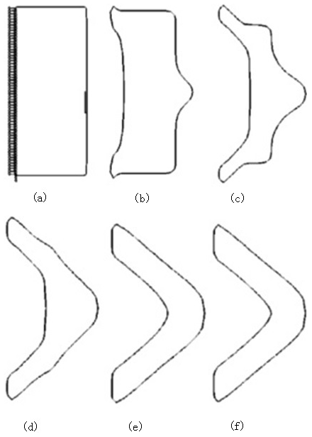
Figure 1Topological optimization process using the level set method: (a) original fixed model with constraints; (b–e) intermediate optimization process for topology optimization; (f) final optimization of the structure shape (Wang et al., 2003).
The current research effort is mainly focused on the use of topology optimization to improve the reliability of a structure in engineering applications and the development of new topology optimization methods to optimize the stiffness of the structure. Shi et al. (2019) proposed a multi-constrained stiffness optimization model based on uncertain loads that solved the structural stiffness optimization problem of the volume and tail joint. Jiao proposed a method to solve the periodic layout optimization problem of cyclically symmetric structures by guiding weights (Jiao et al., 2019). By constructing virtual sector sub-domains, the periodic layout optimization of cyclically symmetric structures was transformed into the conventional topology optimization of virtual sector sub-domains. Additive-free manufacturing technology has been used to design unmanned aerial vehicles (UAVs) and was combined with additive manufacturing technology to carry out the design of lightweight cell, lattice, and honeycomb structures for structures such as wings. Composite materials are used in lightweight design to achieve better design results and performance in practical use (Goh et al., 2017).
Inspired by the scaffolding structure of buildings, Wang et al. (2013) designed a hollow interior with a truss-skin structure on the outside, also known as a skeleton-skin structure. The number of truss nodes and the truss were optimized by topology optimization. The optimized design achieved optimal structural mechanical properties. Additionally, the final printing of the structure was demonstrated through fused deposition molding, and the optimized model material was reduced by approximately 75 % compared to the original model.
Stefan optimized the titanium alloy components of a bionic robot by combining topology optimization technology and additive manufacturing technology, improving the flexibility of the robot's activities to meet the requirements for the finally obtained product (Junk et al., 2018). Cheng et al. (2019) used topology optimization to functionally design gradient lattices for components in additive manufacturing. It was found that the structural framework optimized by the lattice can significantly improve the mechanical properties of the structure and reduce the weight of the components, as shown in Fig. 2 (Cheng et al., 2019).
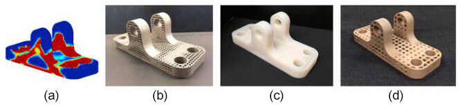
Figure 2Stent optimized using different printing technologies; (a) topology optimization model; (b) direct laser sintering of small lattices; (c) fused deposition molding; (d) direct laser sintering of large lattices (Cheng et al., 2019).
Vaissier et al. (2019) used an improved genetic algorithm to perform topology optimization on a support structure for additive manufacturing. The support structure was designed with a lattice frame, a reduced number of support beams, and a minimized support ratio of the support structure to the print. The model was internally and externally supported, reducing material consumption (Vaissier et al., 2019). Robbins used the topology optimization method to generate a cell structure for the continuum and calculated the macro structure size by assuming that the cell structure was uniform (Robbins et al., 2016). The results show that the topologically optimized structure designed by the cell structure under a load can meet the necessary requirements. The structure can be processed and manufactured by 3D printing equipment, as shown in Fig. 3 (Robbins et al., 2016). Seabra et al. (2016) combined the advantages of additive manufacturing to facilitate the molding of complex structural parts and used topology optimization and selective laser melting to decrease the weight of an aircraft support. The optimized support was then tested. The test results showed that the optimized bracket assembly significantly reduces the overall quality of the structure but improves the safety factor. Belhabib and Guessasma (2017) used the method of moving asymptotes to conduct a finite-element analysis of a 3D fused deposition model (FDM) of a topology-optimized hollow structure and tested the printed 3D model by compression testing to obtain model forces under different load conditions.
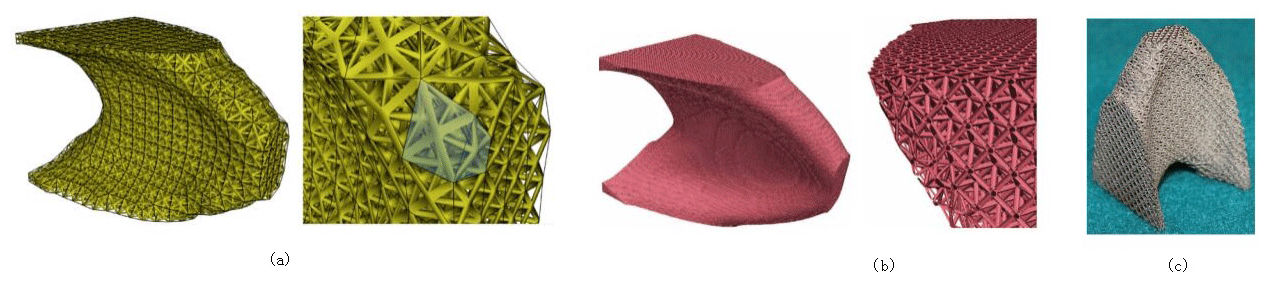
Figure 3Topological optimization of the cell structure and its 3D printed model: (a) coarse mesh cell topology optimization; (b) fine mesh cell topology optimization; (c) stainless steel 3D printing (Robbins et al., 2016).
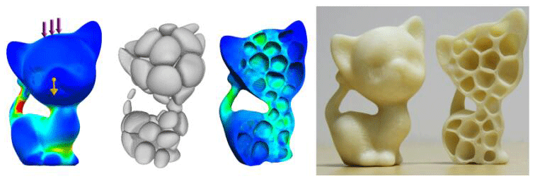
Wang et al. (2018) used the homogenization method to achieve a natural frequency variable density fusion-molded printed honeycomb structure. By optimizing the design of a cantilever plate, natural frequency optimization was demonstrated on the basis of homogenization topology optimization. This method can enhance the natural frequency of a structure and reduce its weight. Lu et al. (2014) proposed an algorithm for hollowing out and filling Voronoi structures based on honeycomb structures inside the model. This algorithm obtains a higher intensity ratio by adjusting the size of each Voronoi unit and the hollowing ratio of each model, as shown in Fig. 4 (Lu et al., 2014). Rezaie et al. (2013) studied the implementation of the topology optimization method during the fused deposition simulation process, proposed a relatively simple method for the application of additive manufacturing to topology optimization, and then implemented the method using the FDM. A comparison of the results shows that even if very basic additive manufacturing equipment is used in the study, the degree of deterioration of the complex contours from topology optimization into a simple honeycomb structure is quite limited. Liu and To (2017) proposed a new method for topology optimization based on a level set. This method solved the two main problems of additive manufacturing design, namely the material anisotropy and self-supporting manufacturability constraints. The multilevel set method was used to solve the 3D parallel design problem. The multilevel set function was used to represent the uniformly sliced additive manufacturing part, and a new interpolation method of the multilevel set function was proposed to solve the problem of self-supporting manufacturability constraints.
To date, few studies have examined the lightweighting of palletizing robots. Most of the research on lightweighting of palletizing robots has focused on the field of lightweight materials, but such lightweight materials are mostly high-strength, difficult-to-machine materials such as titanium alloys. This approach is more expensive than the use of structural optimization design to obtain a lightweight structure of palletizing robots.
The present work does not present a new topology optimization technique or an additive manufacturing method but rather focuses on the combination of topology optimization and additive manufacturing technology. This approach is used to obtain lightweight palletizing robots in order to meet the weight reduction requirements of the palletizing robot while reducing the processing difficulty of the structure after topology optimization. This paper is organized as follows. Section 1 mainly introduces the application of topology optimization in additive manufacturing. Section 2 uses 3D modeling software and finite-element software to model the pallet arm's forearm. In Sect. 3, the lightweight design of the arm of the palletizing manipulator is realized through topology optimization. In Sect. 4, the finite-element analysis of the optimized manipulator's forearm is performed to verify the mechanical properties of the optimized manipulator. In Sect. 5, 3D printing of the arm of the palletizing manipulator after the optimization is completed, and the processing feasibility of the scheme is verified. The conclusions are given in Sect. 6.
2.1 Topology optimization of the continuum based on the density-stiffness interpolation model
Prior to the topology optimization of the structure, the objective function, design variables, and constraints should be determined as the three elements of topology optimization. After these three elements are determined, the general mathematical model of topology optimization can be expressed as follows.
X – in the structural topology optimization problem, one or more sets of design variables corresponding to the objective function; f(x) – objective function, the ultimate goal of topology optimization. Objective functions are mostly the structural flexibility, structural weight, and structural size. gi(x),hi(x) – the constraints in the structural topology optimization process are represented by inequality and equality constraints.
Structural topology optimization is divided into discrete and continuous topology optimization according to the types of optimization variables. Currently, the main optimization methods include the homogenization method, variable density method, variable thickness method, progressive structure optimization method, independent continuous mapping method, and level set method (Lipson and Gwin, 1977). The solid isotropic material penalty model known as SIMP (solid isotropic micro-structure with penalization) is the main interpolation model for variable density topology optimization used in current studies. Prior to optimization, it is necessary to assume that the material density in the design area of the optimization object is variable, and the optimization goal is the material density. The function is the optimal distribution of the material. The advantage of the variable density method is that the calculation time is reduced and the design procedure is simple; its disadvantage is that the solution accuracy is lower than that of the homogenization method (Sethian and Wiegmann, 2000; Sigmund, 1994; Young et al., 1999).
The basic idea of the variable density method is based on the assumption that a solid material is isotropic and that the relative density of the variable material is artificially changed. The density is a design variable, and the empirical formula is used to represent the nonlinear relationship between the elastic modulus and density. This model is called the interpolation model of the variable density topology optimization method (Zuo and Saitou, 2017). The empirical formula for this nonlinear relationship is given by
In the formula, Ei is the material elastic modulus of the ith unit; Emin is the modulus of elasticity of the cavity element with an element density ρi of 0; and E0 is the elastic modulus of a full material unit with a unit density ρi of 1. The value of Emin is usually taken as . f(ρi) is the penalty function.
In the optimization design of the topological structure of the mechanical products studied in this work, the SIMP interpolation model of the variable density method is used. The general form of the interpolation model function with penalty factor p is
In the formula, ρi is the relative element density value, ; ρmin is the lower unit density value, and p is the penalty factor for the interpolation model.
The penalty effect determines the final optimization result. At the same time, the penalty effect is determined by the value of the penalty factor p. When the value is obtained in the space of the penalty factor, a larger value of the penalty factor p will give a greater penalty effect. For the optimization results, an excessively large or excessively small value of p will adversely affect the optimization results.
In this paper, in the topology optimization of the manipulator's forearm, the penalty factor p is set to 0.3 to obtain the best topology optimization result. The SIMP interpolation model based on the variable density method is obtained, with the minimum flexibility as the optimization target and the constraints on the volume and mass fractions of the material. The mathematical model is given by
In the formula, m is the total number of working conditions under each load; ωi is the ith working condition weighted value; p is the penalty factor of the interpolation model, taking p≥2; ci(xe) is the compliance function under the ith working condition and is the objective function; and are the maximum compliance and minimum compliance, respectively, at the ith operating condition; v is the volume of the original structure model before optimization; v0 is the design area volume during topology optimization; v1 is the minimum density unit volume; f is the residual volume percentage after the variable density topology optimization; dt1 and σt1 are the node displacements and stresses of the corresponding elements under the first working condition; and are the upper limit of the joint displacement and the stress of the structural element; xmin is the node and displacement lower limit. The optimization process is illustrated in detail in Fig. 5.

2.2 Robotic forearm simplified model
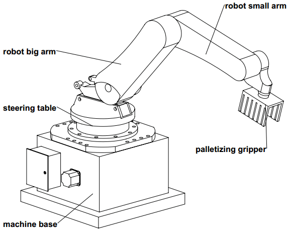
This work aims to perform lightweight structure design of the arm of a numbering manipulator. The palletizing manipulator is mainly composed of a base, a steering table, a robot arm, a robot arm and a pallet gripper, as shown in Fig. 6.
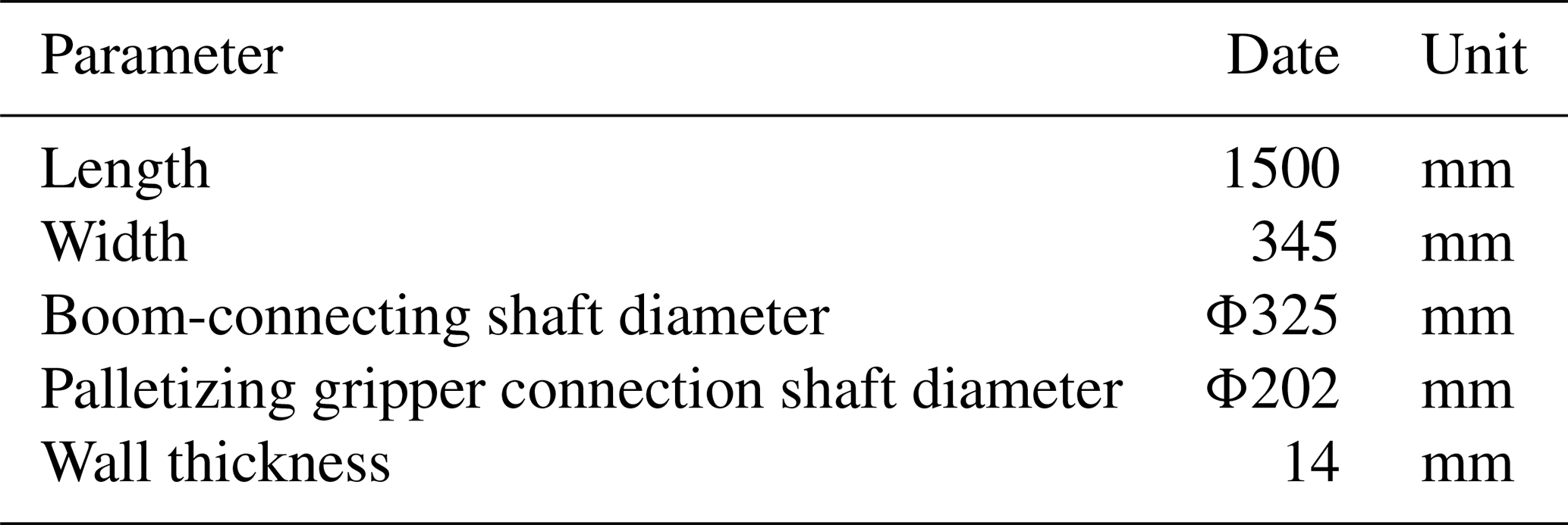
To meet the purpose of use, the model parameters of the pallet arm manipulator arm are analyzed, as shown in Table 1. To ensure that the finite-element software obtains accurate model results during the calculation process, to reduce the calculation time of the finite-element analysis, and to save computer memory resources during the calculation, Solid Works is used to simplify the modeling of the manipulator.
When meshing, the middle part of the forearm of the manipulator is used as the optimization area. To observe the mesh situation and ensure the accuracy of the static and modal analyses, the parameter of the element size is set to 8 mm. The part uses the default mesh size. The number of nodes of the divided robotic arm model is 13 227, the number of meshes is 73 382, and the meshed robotic arm model is shown in Fig. 7.

The material of the manipulator forearm mostly uses lightweight materials such as cast aluminum or Q235. These materials are used to ensure the accuracy of the movement and the flexibility for grasping the material. The properties of the material are shown in Table 2.

Under extreme conditions, the manipulator forearm is connected to the manipulator arm through the forearm connection shaft. In this case, the manipulator forearm can be regarded as a fixed constraint. According to the above analysis, considering the weight and external load of the palletizing gripper, the manipulator forearm has an end load of 600 N.
2.3 Static analysis of the manipulator forearm
A load of 600 N was applied to the manipulator forearm along the negative direction of the z axis, and the model was subjected to a static analysis and a static cloud diagram, as shown in Fig. 8.
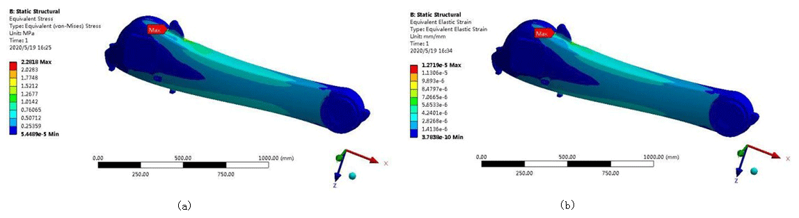
Figure 8Static cloud diagram of the manipulator forearm model; (a) equivalent stress cloud diagram; (b) equivalent strain cloud diagram.
Figure 8 shows that the maximum equivalent stress appears at the connecting shaft of the boom in the model. The maximum equivalent stress is 2.28 MPa, which is far below the material's yield limit of 235 MPa. The maximum equivalent strain of the manipulator's forearm also appears near the connecting axis of the arm, and the maximum deformation of the joint is mm. Under the condition of its own weight and external load, the manipulator forearm exhibits a stress concentration and bending deformation under the limit lifting conditions. This phenomenon makes the node mesh larger in terms of the deformation relative to the other parts.
2.4 Modal analysis of the robotic arm
Using ANSYS Workbench to perform a modal analysis of the manipulator forearm model, the natural frequencies and corresponding modes of the palletizing manipulator forearm were determined, and the first six modes of the manipulator forearm for analysis were selected. Using the finite-element method to obtain the mode shapes of the forearm modes up to sixth order as shown in Fig. 9, the natural frequency and mode analysis was performed, with the result shown in Table 3.

Figure 9First six-order modes: (a) first-order mode; (b) second-order mode; (c) third-order mode; (d) fourth-order mode; (e) fifth-order mode; (f) sixth-order mode.
Table 3Analysis of the natural frequencies and mode shapes of the first six modes.
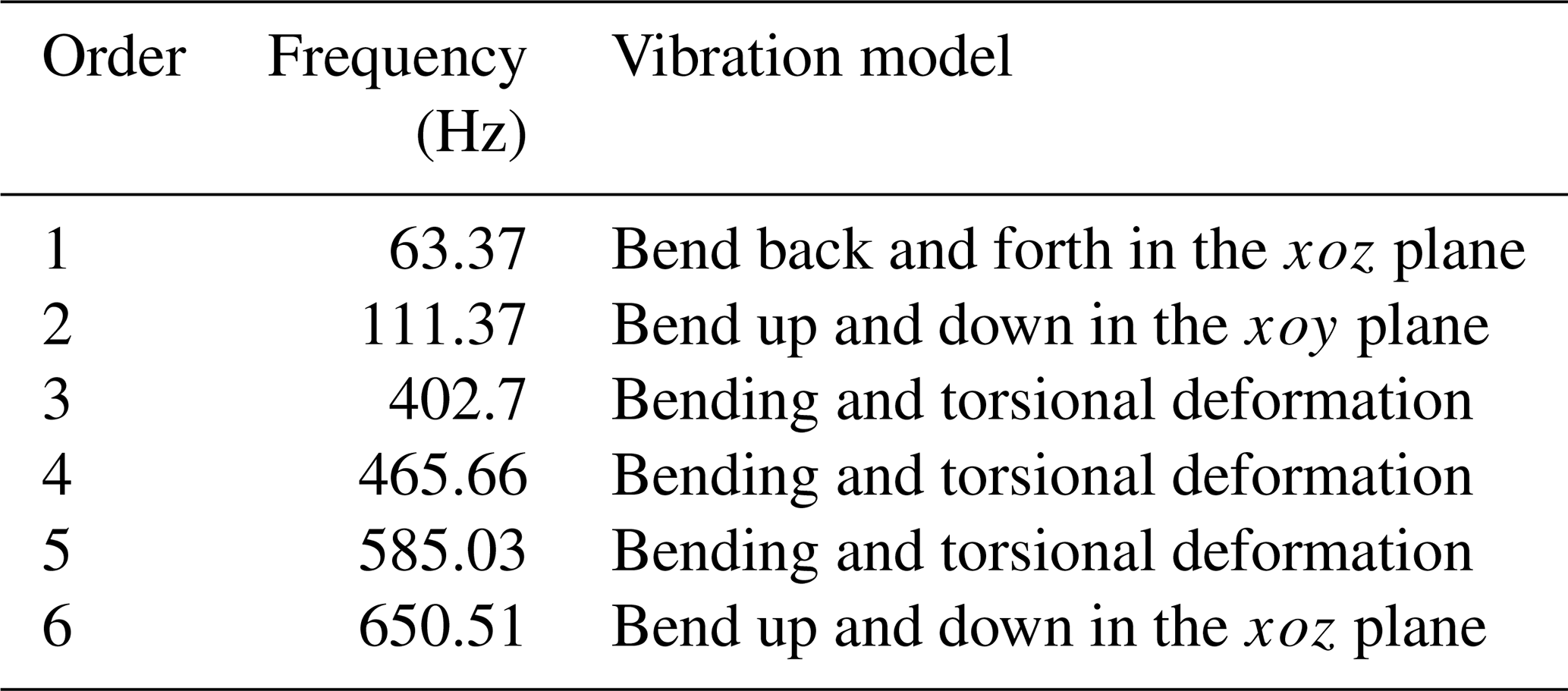
An examination of the results presented in Fig. 9 and Table 3 shows that the fundamental frequency of the first-order mode is 63.37 Hz. As the mode order number increases, the corresponding modal frequency also increases. The frequency is in a higher frequency range, so that the manipulator forearm has good rigidity and a large optimization space, avoiding resonance phenomena.
The SIMP interpolation model of the variable density method combined with ANSYS Workbench optimization software was used to optimize the structural topology of the manipulator forearm.
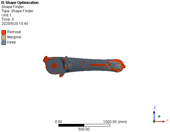
Using the middle part of the manipulator arm as the optimization area, the relative density of the structural unit is taken as the design variable, the size and volume fraction of the manipulator arm below a certain value are taken as the constraints, and the minimum flexibility is taken as the optimization goal. Using the ANSYS Workbench for topology optimization, the optimization constraint of 30 % is set for the topology optimization model. The results are shown in Fig. 10. The dark area of the optimized area represents a density value of 0 corresponding to the removed area, and the non-dark area represents a density value of 1 corresponding to the reserved area. The remainder of the colors are in between 0 and 1, and the proportion of the total area occupied by these values is small.
3.1 Two forearm models based on a Rhino Grasshopper
For the topology optimization of the forearm of the manipulator, Solid Works is first used to model the 3D structure of the forearm of the manipulator and simplify the structural features, and then ANSYS Workbench is used for finite-element analysis, and the manipulator is verified by static analysis and modal analysis of the forearm of the manipulator. The optimized space of the forearm under external load is optimized by the continuous variable density topology optimization method to obtain a preliminary topology optimized structure model, and the Solid Works and Rhino design software is combined to create a secondary reconstruction model of the robot arm; then ANSYS Workbench compares the excellent mechanical properties of the two structural models and finally realizes the 3D printing of the two structures, providing a reference solution for the structural design and manufacturing of the palletizing robot arm. A detailed block diagram of the palletizing robot arm lightweight design is shown in Fig. 11.

The topologically optimized structure obtained by the finite-element method is used as a reference, and the secondary reconstruction design of the model is performed because the boundary of the structure is in a zigzag checkerboard. This is also called the Voronoi diagram. According to previous research, the hexagonal honeycomb structure has the characteristics of high strength, low weight, heat dissipation, and energy absorption. Following the continuous development of the materials and processing methods of the honeycomb structure, it has been gradually applied to the fields of lightweight structure design in aerospace and other industries. The Voronoi structure is a special form of the honeycomb structure, and the Voronoi unit is also a representative of the steady-state structure of the regular hexagonal structure. Therefore, this study uses the Voronoi structural unit to design the lightweight palletizing manipulator forearm.
3.1.1 Filled endoskeleton Voronoi structural design
The Rhino Grasshopper parametric modeling software is used to design the internal honeycomb skeleton structure of the robot forearm. The specific design steps are the following.
-
Step 1: import the original model of the forearm into the program box.
-
Step 2: fill the box with random points.
-
Step 3: generate the corresponding Tyson polygon at random points.
-
Step 4: enlarge the honeycomb structure, keeping the linear structure.
-
Step 5: delete redundant coincident line types.
-
Step 6: use the linear structure to generate a honeycomb tubular structure.
-
Step 7: cut off the allowance of the external honeycomb structure of the model.
-
Step 8: perform the Boolean operation between the model shell and Tyson polygon structure.
-
Step 9: convert format and generate entity.
The specific design process is shown in Fig. 12. The optimized arm model of the palletizing robot obtained using this process is shown in Fig. 13.
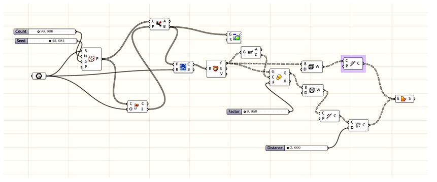
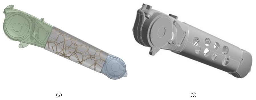
Figure 13Optimized forearm model: (a) arm model after filling; (b) overall material removal model.
3.1.2 Design of the Voronoi structure with nested external removal
The realization of the Voronoi structure in the design area of the manipulator forearm is performed by the Rhino Grasshopper module, and the specific design steps are as follows.
-
Step 1: spread out the side surface of the model as a flat surface.
-
Step 2: fill in random points on the side surface after tiling.
-
Step 3: generate the corresponding plane Thiessen polygon structure from random points.
-
Step 4: enlarge the Tyson polygon structure, keeping the linear structure.
-
Step 5: delete redundant coincident line types.
-
Step 6: take back the flat side surface to the model surface.
-
Step 7: use the linear structure to generate a Tyson polygon tubular structure.
-
Step 8: perform the Boolean operation.
-
Step 9: convert the format and generate the entity.
The robot arm model of the random point of the Voronoi structure is obtained, as shown in Fig. 14.
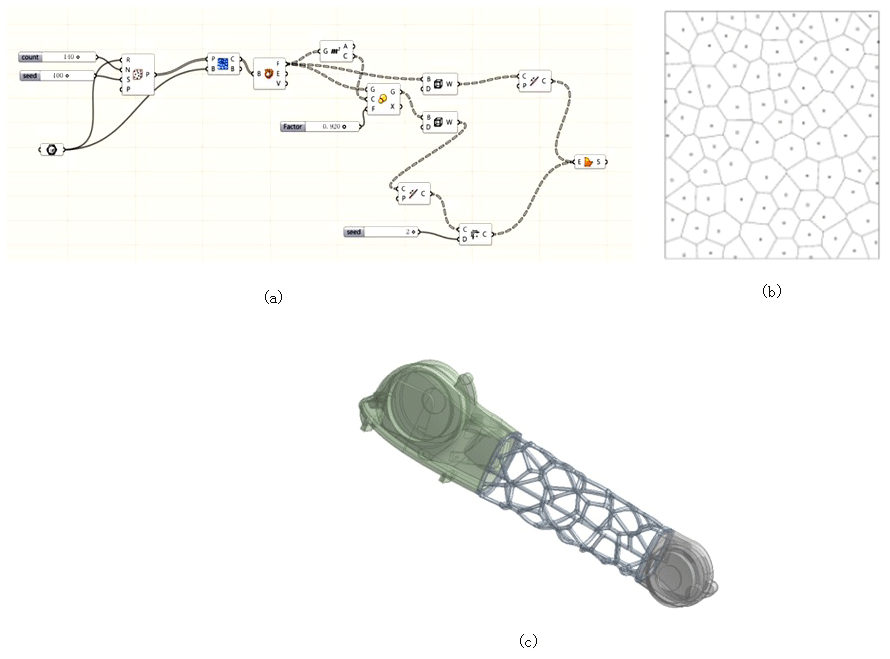
Figure 14Voronoi structural design of nested external removal: (a) procedural process; (b) Voronoi diagram random points; (c) Voronoi diagram mechanical arm model.
4.1 Structural performance analysis of the filled endoskeleton Voronoi structure
Static and modal analyses are performed on the optimized forearm model, and a static analysis is performed on the optimized forearm, as shown in Fig. 15. Figure 15 shows that the maximum stress value of the optimized forearm is 8.66 MPa, which is far lower than the material yield strength of 235 MPa and has a sufficient safety margin. The maximum displacement value is mm, and the deformation is small. The requirements for the mechanical properties of the robot arm are met. A comparison of the performance characteristics before and after forearm optimization is shown in Table 4.
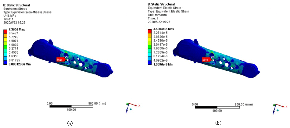
Figure 15Static cloud map after robot forearm optimization: (a) stress cloud map after optimization; (b) model displacement cloud map after optimization.
Table 4Performance comparison before and after forearm optimization.
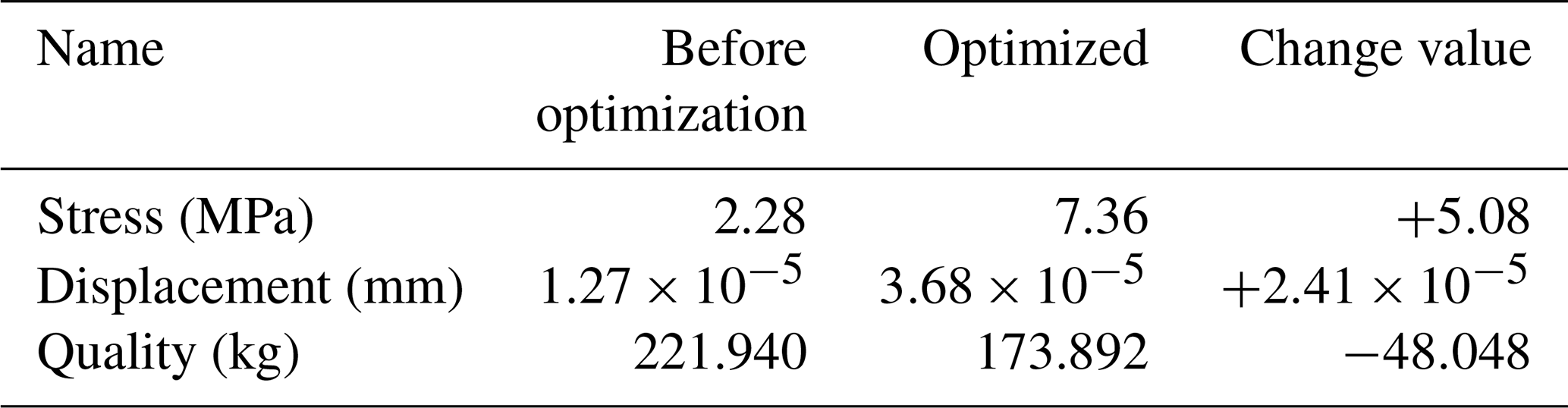
An examination of the results presented in Table 4 shows that after the optimization of the forearm, the maximum stress and the maximum displacement have increased. The maximum stress has increased by approximately 5.08 MPa, the maximum displacement has increased by approximately mm, and the change is very small. The overall performance of the forearm is basically unchanged. The total weight of the model of the forearm is reduced from 221.940 to 173.892 kg, corresponding to a reduction of approximately 22 %, achieving the goal of weight reduction.
The same method as that of the original model is used to perform modal analysis of the optimized bone-filled forearm. The resulting mode diagram is shown in Fig. 16. The results of the modal analysis of the forearm and the vibration mode are shown in Table 5.
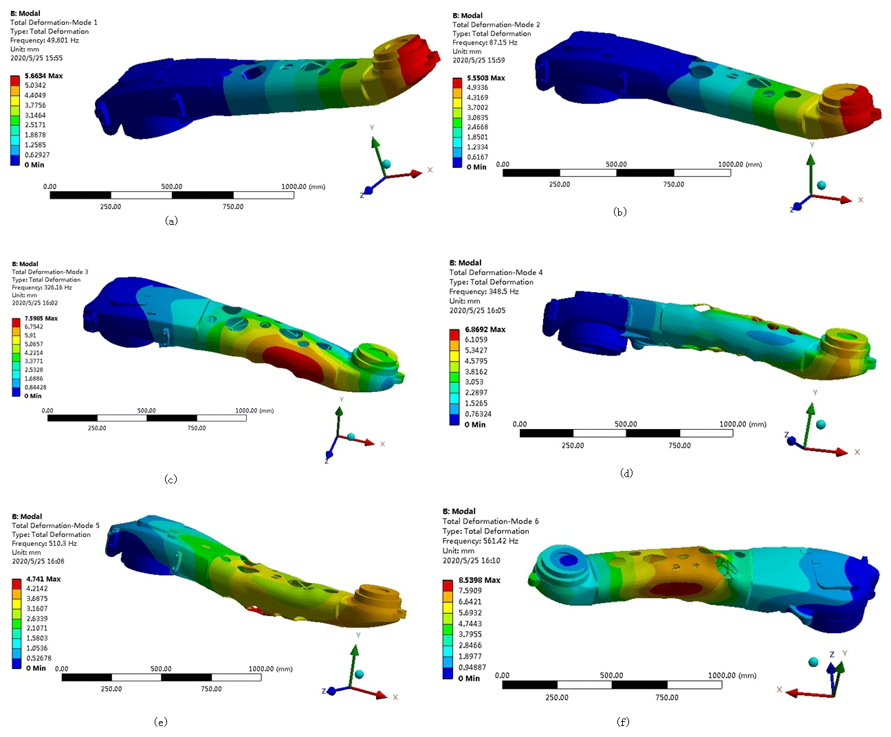
Figure 16First six-order modes of the bone-filled forearm: (a) first-order mode; (b) second-order mode; (c) third-order mode; (d) fourth-order mode; (e) fifth-order mode; (f) sixth-order mode.
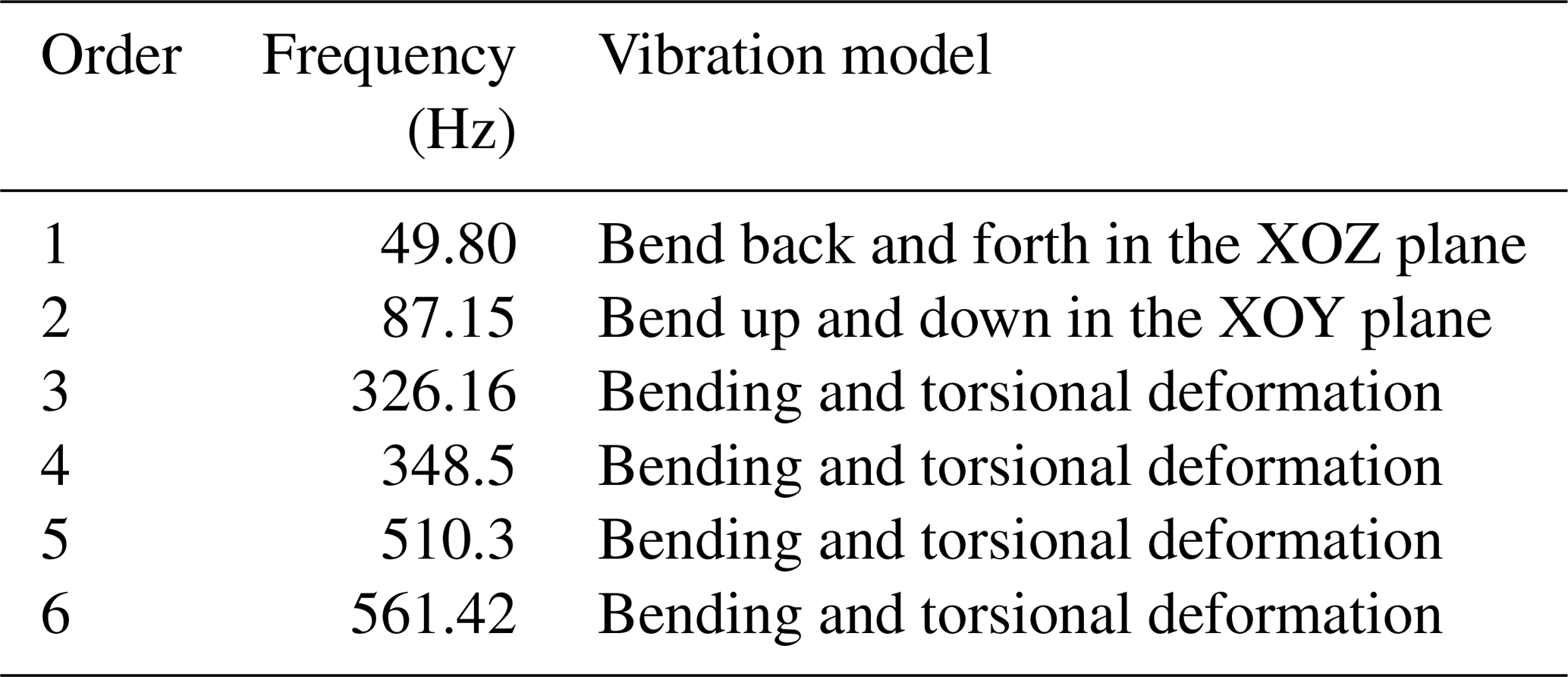
An examination of the data presented in Table 5 shows that the first six-order modal frequencies of the robot's forearm optimization are in the range of 49.801–561.42. Although the natural frequency of the forearm optimization has been reduced to some degree, it is much higher than the working vibration frequency of the palletizing robot at 15 Hz. Thus, design of the arm can avoid the occurrence of resonance phenomena.
4.2 Performance analysis of the nested externally removal Voronoi structure
Using the same load and boundary conditions, the finite-element analysis of three Voronoi structure manipulator models at different random points after optimization is performed. The static cloud diagram obtained by the analysis is shown in Fig. 17. The data for the comparison of performance and quality between the optimized model and the original manipulator's forearm are shown in Table 6.

Figure 17Static analysis of the optimized manipulator arm model: (a) random point equivalent stress cloud diagram; (b) random point equivalent strain cloud diagram.
Table 6Comparison of the structure and performance of the new manipulator forearm model and the original model.
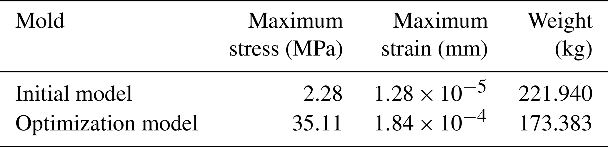
Table 6 shows that although the maximum stress and maximum strain of the optimized manipulator arm are increased, the maximum stress is less than the material's yield limit of 235 MPa, and the maximum strain is only mm, which is within the allowable deformation range of the manipulator arm. The quality of the optimized model is reduced by approximately 22 % compared to the original model. From the above analysis, it is observed that the optimized manipulator arm meets the design requirements and achieves the purpose of a lightweight structure.
The modal analysis of the first six-order frequency is performed on the nested externally removable manipulator using modal analysis. The resulting mode diagram is shown in Fig. 18, and the specific mode data are shown in Table 7.
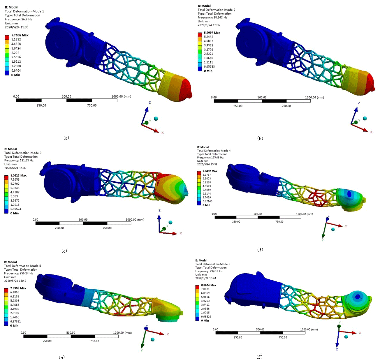
Figure 18First six-order modes of the nested external removal: (a) first-order mode; (b) second-order mode; (c) third-order mode; (d) fourth-order mode; (e) fifth-order mode; (f) sixth-order mode.
4.3 Comparison of the performance of the two optimized arm models
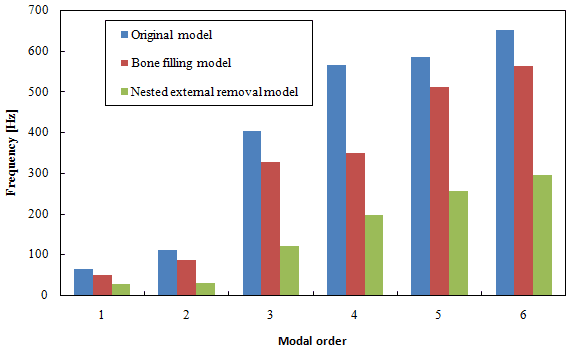
A comparative performance analysis is carried out for the above two optimized forearm models. For quality, the two optimized models show a reduction by 22 % compared to the original model. Under this condition, the performance of the optimized models is compared. A comparison of the stress and strain of the two models shows that the maximum stress of the bone-filled model is 7.36 MPa, the maximum stress of the nested external removal model is 35.11 MPa, and the stress of the bone-filled model is lower than that of the nested removal model. At the same time, for strain, the maximum strain of the bone-filled model is mm and the maximum strain of the nested external removal model is mm, so that the strain of the bone-filled model is also lower than that of the nested removal model. The stress and strain of both are within the allowable range, as shown in Fig. 19.
Table 7Optimal nested-external-removal-type first six-order modes of the small arm.
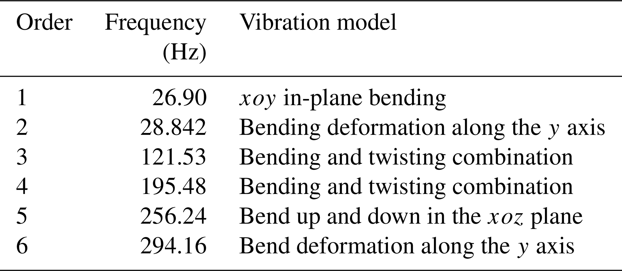
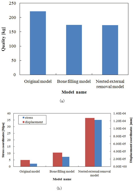
Figure 19Comparison of the performance of the two optimized models: (a) quality comparison between the two optimized models and the original model; (b) stress–strain comparison between the two optimized models.
The modal comparison and analysis of the two optimized models and the original model shows that the first-order frequency of the bone-filled model is 49.8 Hz, and the first-order frequency of the externally removed model is 29.8 Hz. Both are 15 Hz higher than the working frequency of the manipulator arm, avoiding the occurrence of resonance. This is shown in Fig. 20.
For the manipulator arm designed in this paper, the traditional manufacturing method for the fabrication of the porous structure is too complicated and cannot be carried out. In recent years, it was demonstrated that the combination of topology optimization and additive manufacturing can solve the processing and molding problems caused by topology optimization results. To verify the feasibility of the use of additive manufacturing technology to solve the problem of processing of complex structures after the topological optimization design of the robotic arm, the FDM was used to 3D print the traction chassis model.
According to the results of the abovementioned model optimization analysis, the optimized forearm model is saved in the STL format in Solid Works and then imported into the Cura slicing software for layered slicing processing. Next, the fusion deposition molding printer is used to realize 3D printing of the palletizing robot forearm model, as shown in Fig. 21.
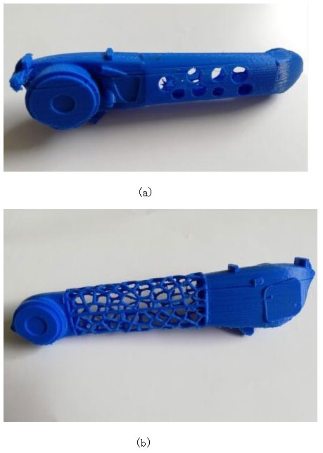
Figure 213D printed model of the robot's forearm; (a) 3D-printed model of the filled-in skeletal Voronoi structure; (b) 3D-printed model of the Voronoi structure with nested outer removal.
Taking the forearm of a number stacking robot as a research object, the analysis and design of the lightweight structure were carried out. Through the structural analysis of the palletizing robot, a simplified model of the manipulator forearm was created. The finite-element ANSYS Workbench software was used to perform static and modal analyses of the forearm under typical working conditions. The model stress and strain were obtained. Based on the cloud diagram of the topology optimization results, two different lightweight models of the manipulator arm of the filled-in-skeleton and nested-external-removal Voronoi structures were designed. The optimized model of the manipulator arm with the nested-external-removal-type Voronoi structure can be applied in the cases where the load weight ratio is high, the structure is lightweight, the control circuit is complicated, and the wiring must be routed inside the robot arm, while the bone-filled Voronoi structure manipulator arm is more suitable for lightweight structures under heavy loads and where external wiring is possible. The two optimized structures proposed in this paper can meet most of the topological optimization and lightweight requirements in the field of industrial robots and provide guidance for the structural optimization design and development of industrial robots. The mechanical properties and quality of the structure between the new model and the original model were compared. To ensure the structural performance of the manipulator forearm limit, the structural quality of the two optimized models was reduced from 222 to 173 kg, reaching the manipulator forearm and achieving the goal of lightweight design. Finally, 3D printing technology was used to realize the model processing of the two structures. The use of 3D printing digital manufacturing technology and computer-aided digital design technology provides a set of feasible solutions for the personalized design and manufacturing of the manipulator forearm.
All the code used in this paper can be obtained upon request from the corresponding author.
All the data used in this paper can be obtained upon request from the corresponding author.
JC established an overall paper research framework, QC conducted detailed optimization and data experiments on the overall paper, and HY carried out paper revisions and financial support of the paper.
The authors declare that they have no conflict of interest.
This work was supported by the National Natural Science Foundation of China (NSFC grant no. 61303087) and the Major Scientific and Technological Innovation Projects (grant no. 2019JZZY010455). The authors thank a senior editor from American Journal Experts for linguistic advice.
This research has been supported by the National Natural Science Foundation of China (grant no. 61303087) and the Major Scientific and Technological Innovation Projects (grant no. 2019JZZY010455).
This paper was edited by Jeong Hoon Ko and reviewed by Lin Lu and one anonymous referee.
Anders, C., Niels, A., and Ole, S.: Ploiting Additive Manufacturing Infill in Topology Optimization for Improved Buckling Load, Engineering, 2, 250–257, https://doi.org/10.1016/J.ENG.2016.02.006, 2016.
Belhabib, S. and Guessasma, S.: Compression performance of hollow structures: from topology optimisation to design 3D printing, Int. J. Mech. Sci., 133, 728–739, https://doi.org/10.1016/j.ijmecsci.2017.09.033, 2017.
Cheng, L., Bai, J. X., and Albert, C. T.: Functionally graded lattice structure topology optimization for the design of additive manufactured components with stress constraints, Comput. Method. Appl. M., 344, 334–359, https://doi.org/10.1016/j.cma.2018.10.010, 2019.
Fleury, C.: Structural weight optimization by dual methods of convex programming, Int. J. Numer. Meth. Eng., 14, 1761–1783, https://doi.org/10.1002/nme.1620141203, 1979.
Fleury, C. and Sander, G.: Dual methods for optimizing finite element flexural system, Comput. Method. Appl. M., 37, 249–275, https://doi.org/10.1016/0045-7825(83)90078-6, 1983.
Goh, G. D., Agarwala, S., Goh, G. L., Dikshit, V., Sing, S. L., and Yeong, W. Y.: Additive manufacturing in unmanned aerial vehicles (UAVs): Challenges and potential, Aerosp. Sci. Technol., 63, 140–151, https://doi.org/10.1016/j.ast.2016.12.019, 2017.
Haftka, R. T.: Second-order sensitivity derivatives in structural analysis, AIAA Journal, 20, 1765–1766, https://doi.org/10.2514/3.8020, 1982.
Haftka, R. T. and Grandhi, R. V.: Structural shape optimization – A survey, Comput. Method. Appl. M., 57, 91–106, https://doi.org/10.1016/0045-7825(86)90072-1, 1986.
Huang, X., Zhou, S. W., Xie, Y. M., and Li, Q.: Topology optimization of microstructures of cellular materials and composites for macrostructures, Computat. Mater. Sci., 67, 397–407, https://doi.org/10.1016/j.commatsci.2012.09.018, 2013.
Jiao, H. Y., Li, Y., and Yang, L. Y.: Periodic Layout Optimization of Cyclic Symmetric Structure, IEEE Access, 7, 55269–55276, https://doi.org/10.1109/ACCESS.2019.2913188, 2019.
Junk, S., Klerch, B., Nasdala, L., and Hochberg, U.: Topology optimization for additive manufacturing using a component of a humanoid robot, Procedia CIRP, 70, 102–107, https://doi.org/10.1016/j.procir.2018.03.270, 2018.
Lipson, S. L. and Gwin, L. B.: The complex method applied to optimal truss configuration, Comput. Struct., 7, 461–468, https://doi.org/10.1016/0045-7949(77)90083-9, 1977.
Liu, J. and To, A. C.: Deposition path planning-integrated structural topology optimization for 3D additive manufacturing subject to self-support constraint, Computer-Aided Design, 91, 27–45, https://doi.org/10.1016/j.cad.2017.05.003, 2017.
Lu, L., Sharf, A., Zhao, H. S., Wei, Y., Fan, Q. N., Chen, X. L., Savoye, Y., Tu, C. H., Cohen-Or, D., and Chen, B. Q.: Build-to-Last: Strength to Weight 3D Printed Objects, ACM T. Graphic., 33, 97, https://doi.org/10.1145/2601097.2601168, 2014.
Rezaie, R., Badrossamay, M., Ghaie, A., and Moosavi, H.: Topology Optimization for Fused Deposition Modeling Process, Procedia CIRP, 6, 521–526, https://doi.org/10.1016/j.procir.2013.03.098, 2013.
Robbins, J., Owen, S. J., Clark, B. W., and Voth, T. E.: An efficient and scalable approach for generating topologically optimized cellular structures for additive manufacturing, Additive Manufacturing, 12, 296–304, https://doi.org/10.1016/j.addma.2016.06.013, 2016.
Seabra, M., Azevedo, J., Araujo, A., Reis, L., Pinto, E., Alves, N., Santos, R., and Mortagua, J. P.: Selective laser melting (SLM) and topology optimization for lighter aerospace componentes, Procedia Structural Integrity, 1, 289–296, https://doi.org/10.1016/j.prostr.2016.02.039, 2016.
Sethian, J. A. and Wiegmann, A.: Structural Boundary Design via Level Set and Immersed Interface Methods, J. Computat. Phys., 163, 489–528, https://doi.org/10.1006/jcph.2000.6581, 2000.
Shi, D. Y., Ma, H., and Teng, X. Y.: A structure topology optimization with the first order saddle point approximation, IEEE Access, 7, 98174–98181, https://doi.org/10.1109/ACCESS.2019.2927141, 2019.
Sigmund, O.: Materials with prescribed constitutive parameters: An inverse homogenization problem, Int. J. Solids Struct., 31, 2313–2329, https://doi.org/10.1016/0020-7683(94)90154-6, 1994.
Sokolowski, J. and Zochowski, A.: On the topological derivative in shape optimization, SIAM J. Control Optim., 37, 1251–1272, https://doi.org/10.1137/S0363012997323230, 1999.
Vaissier, B., Pernot, J. P., Chougrani, L., Veron, and P.: Genetic-algorithm based framework for lattice support structure optimization in additive manufacturing, Computer Aided Design, 110, 11–23, https://doi.org/10.1016/j.cad.2018.12.007, 2019.
Wang, M. Y., Wang, X. M., and Guo, D. M.: A level set method for structural topology optimization, Comput. Method. Appl. M., 192, 227–246, https://doi.org/10.1016/j.advengsoft.2004.06.004, 2003.
Wang, W. M., Wang, T. F. Y., Yang, Z. W., Liu, L. G., Tong, X., Tong, W. H., Deng, J. S., Chen, F. L., and Liu, X. P.: Cost-effective printing of 3D objects with skin-frame structures, ACM T. Graphic., 32, 177, https://doi.org/10.1145/2508363.2508382, 2013.
Wang, X., Zhang, P., Ludwick, S., Belski, E., and To, A. C.: Natural frequency optimization of 3D printed variable-density honeycomb structure via a homogenization-based approach, Additive Manufacturing, 20, 189–198, https://doi.org/10.1016/j.addma.2017.10.001, 2018.
Young, V., Querin, O. M., Steven, G. P., and Xie, Y. M.: 3D and multiple load case bi-directional evolutionary structural optimization (BESO), Struct. Optimization, 18, 183–192, https://doi.org/10.1007/BF01195993, 1999.
Zhang, P. C., Zhang, L. Y., Yang, J., and Gui, Z. G.: The Aperture Shape Optimization Based on Fuzzy Enhancement, IEEE Access, 6, 35979–35987, https://doi.org/10.1109/ACCESS.2018.2849208, 2019.
Zuo, W. and Saitou, K.: Multi-material topology optimization using ordered SIMP interpolation, Struct. Multidiscip. O., 55, 477–491, https://doi.org/10.1007/s00158-016-1513-3, 2017.
- Abstract
- Introduction
- Finite-element modeling of the palletizing manipulator arm
- Topology optimization design of the robot manipulator
- Optimized finite-element analysis
- Topology optimization components for additive manufacturing
- Conclusions
- Code availability
- Data availability
- Author contributions
- Competing interests
- Acknowledgements
- Financial support
- Review statement
- References