the Creative Commons Attribution 4.0 License.
the Creative Commons Attribution 4.0 License.
 | 01 Mar 2021
Topology optimization design of a lightweight integrated manifold with low pressure loss in a hydraulic quadruped robot actuator
Hsinpu Huang
Junhui Zhang
Bing Xu
Gan Liu
Qingyou Luo
Ximeng Wang
In recent years, hydraulic quadruped robots have received increasing attention because of their strong environment adaptability and high load capacity. However, weight control is an important issue for mobile systems in consideration of limited onboard energy. Overweight will cause extra load on joints, reduce the flexibility of movement, and consume more power. Topology optimization is an effective tool to reduce volume and weight while maintaining enough strength. This article takes both optimal geometries and contained flow channels into consideration and gives solutions to structure design and good print quality in a manifold used on a robot. Using topology optimization, the volume of the manifold is further reduced by 50.7 %, while it can meet the mechanical requirement for actual application.
- Article
(5056 KB) - Full-text XML
- BibTeX
- EndNote


The hydraulic quadruped robot can be traced back to the 1960s: GE and the United States Army developed a hydraulic servomotor system-driven quadruped robot, called Walking Truck (Mosher, 1968). This attracted the attention of other research teams and generated widespread research, such as the Kumo-I and Titan series robots developed by the Tokyo Institute of Technology (Hirose and Kato, 2000; Kitano et al., 2013), KOLT by Ohio State University, and BigDog by Boston Dynamics (Playter et al., 2006). At present, more hydraulic quadruped robots are still in urgent development, and scholars have studied the improvement of the mobile performance of the robot, the light weight of the mechanical structure, and the improvement of the overall energy utilization.
The faster speed is one prior developing trend in quadruped robots. In 2012, Boston Dynamics launched the Cheetah prototype (Li et al., 2011), and the travel speed was increased to 45.5 km h−1. The highly integrated WildCat (Simon, 2015) was launched in the following year, which can achieve high-speed running in variant environments with different gaits. The Italian Institute of Technology (IIT) has developed a fully hydraulically driven quadruped robot, HyQ (Semini, 2010; Semini et al., 2008, 2010, 2011), which uses high-precision hydraulic components and high-precision position and torque sensors for each joint to achieve accurate motion. In recent years, the IIT has cooperated with Moog to use the Integrated Smart Actuator (ISA) on HyQ-real, which increases the power-to-weight ratio of the system, and the robot has highly reliable and efficient hydraulic actuation (Barasuol et al., 2018).
Limited energy access on mobile systems is an obstacle for robots, especially for high-speed and heavy-load robots. Weight reduction is expected to be a necessary method which can reduce extra onboard energy consumption by reducing weight. Elasswad et al. (2018) optimized the actuator of the humanoid robot HYDROïD and verified and analyzed the original mechanical structure through a neural algorithm. In order to reduce weight, part of the original metal area is replaced by carbon fiber. Reduce the weight of the original 125 kg robot to 97 kg. Hyon et al. (2013) also optimized the actuator for hydraulic legs, replacing the link mechanism in the actuator with carbon-fiber-reinforced plastic material to achieve a 1 : 1 weight result between the actuator and other devices, and the experimental results of a single foot are presented. The MiniHyQ is the lightest hydraulic quadruped robot today, with a total weight of only 35 kg. It uses the smallest hydraulic pump and other hydraulic components that meet the needs of the work. It uses a tighter mechanical structure to reduce unnecessary materials. In the hydraulic system, the centralized manifold replaces the distributed one, so that the manifold with the same function has less volume and weight, which further reduces the weight of the quadruped robot (Khan et al., 2015a, b). Semini et al. (2015) optimized the manifold of the HyQ2Max robot and adopted the design idea of 3D printing to improve the traditional manifold, which has low material usage ratio and auxiliary holes. However, the above methods for reducing the weight of the hydraulic system adopts the trial-and-error method, and then the corresponding working conditions are tested to determine whether the parts meet the working requirements or not. Although all the above studies have shown satisfying results in mass reduction, most research is still based on experience and is inconvenient enough to engineers.
It is pointed out that topology optimization is an effective means of minimum weight and guaranteed performance, and this method has wide applications in the aerospace field (Zhu et al., 2016). Researchers such as EADS try to optimize the structure of the aircraft by using topology optimization so that it has a light weight and high-rigidity design. The final design model was completed through metal additive manufacturing. The overall procedure saves up to 64 % of the weight while retaining mechanical properties (Tomlin and Meyer, 2011). Hansen and Andersen (2005) used the topology optimization method to perform optimization on the entire hydraulic system, taking into account the various components and working conditions in the system, so that the results can be used with the most economical components and then achieve weight reduction requirements. Kubo et al. (2017) used the topology optimization method to optimize the internal channel of the manifold to obtain the minimum pressure loss. Even so, the combination of low-pressure loss and small volume and mass is still worth investigating.
This article is different from the traditional manifold design method. It takes static structure strength and flow paths as well as manufacturing convenience into consideration using the topology optimization technology.
2.1 Robot structure
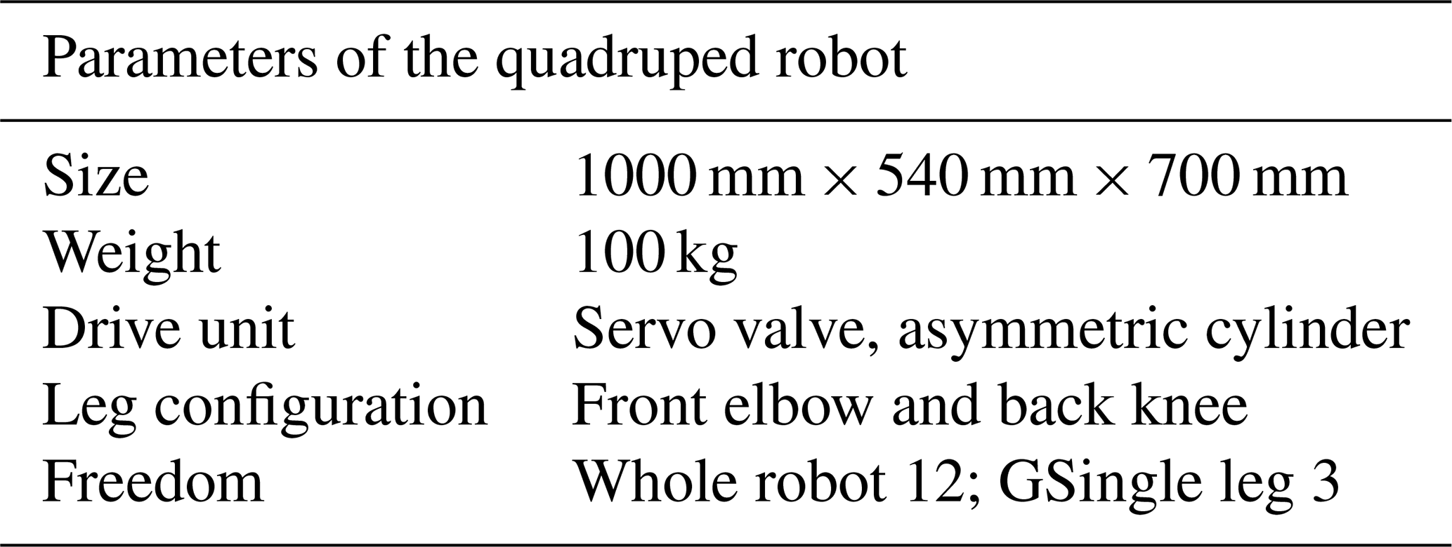
Figure 1 is the skeleton of the quadruped robot under research, and the design object (the actuator and manifold) in this article is shown. The quadruped robot has the characteristics of symmetrical and compact structure and flexible movement. The designed technical indexes are listed in Table 1. It adopts the front elbow and rear knee structure, which is the form of most natural quadruped mammals in nature. It has been widely acknowledged that the leg distribution structure of the front elbow and rear knee improves the obstacle surmounting ability and movement stability in complex terrain and reduces the slip (Meek et al., 2008; Zhang et al., 2005).
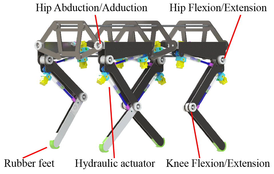
The motion of four legs is driven by linear actuators, and the joint motion mode is shown in Fig. 2. When the actuator is in the limit position of legs (points a and b), the hydraulic cylinder is in the same horizontal state. This design ensures that the effective force arm has a small change in length l, which is conducive to the control of the drive unit and at the same time can ensure that the rotating mechanism has a sufficiently large rotation angle β.

2.2 Hydraulic system
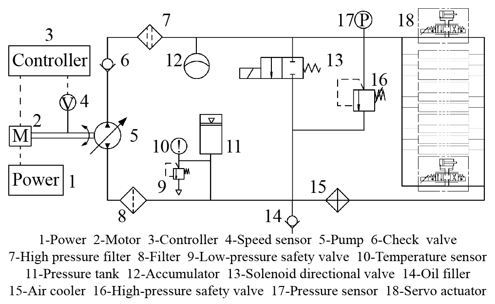
The hydraulic system has the characteristics of a high power-to-mass ratio, a large load-bearing capacity, a wide speed range, and various speed control modes, which make it particularly suitable for a quadruped robot to deal with variant environments. The actuator composed of a hydraulic cylinder and a hydraulic valve is the functional part to realize reciprocating movement that is the basic motion model for every joint control. For each leg, there are two actuators mounted on the hip and one mounted on the knee, respectively, and the hydraulic system diagram is shown in Fig. 3.
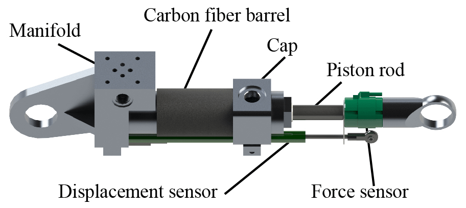
A high-force and light actuator should be designed for mobile robots. This can contribute to high power density by reducing unnecessary material, reducing the power required for system operation and increasing the loading capacity of the device. For the rigid body part, relevant lightweight research was carried out in our lab. For example, we have changed the barrel region to carbon fiber and metal composites, which can also be observed in Elasswad et al. (2018). In addition to carbon fiber, aluminum alloy materials are also used in other areas. Aluminum alloy has a lower density, and the parts made of aluminum alloy material have a better weight advantage under the same volume. However, aluminum alloy does not have better welding performance like steel, so parts are not suitable for additional welding processes after forming. Shown in Fig. 4, aluminum alloy replaces conventional high-density steel materials whose ultimate strength is 455 MPa, further reducing the weight of the actuator. However, even if the mass of the actuator has been greatly reduced, there are still many areas that can be optimized, and this can be effectively achieved through topology optimization.
3.1 Original manifold model
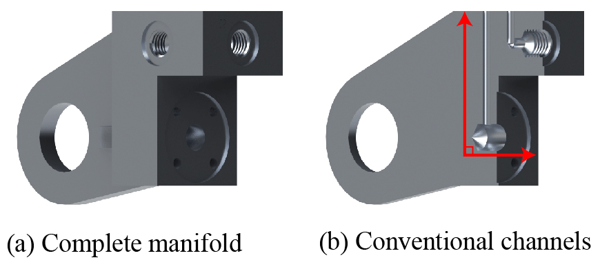
The manifold mounted on the end of the actuator has two functions, working as the structural part as well as the valve installation baseplate. The original manifold model adopts the traditional design method that is subject to the conventional manufacturing method. It is made by milling and drilling, and the flow channels are sharply crossed as shown in Fig. 5b. From our previous study (Liu et al., 2019), the form of the flow path has determined effects on pressure loss and caused additional energy dissipation, which should be avoided in actuator design.
On the other hand, the conventional design also introduces redundant mass and volume that is unnecessary. Constrained by traditional manufacturing, the manifold block usually has regular geometries, and this occupies large space. The volume of the model is 108 255.8 mm3, while the weight is up to 304.2 g.
In this mean, the optimization of this manifold has two meanings: one is reduced pressure loss by flow path optimizing and another is cutting down additional energy loss by reducing weight.
3.2 Topology optimization
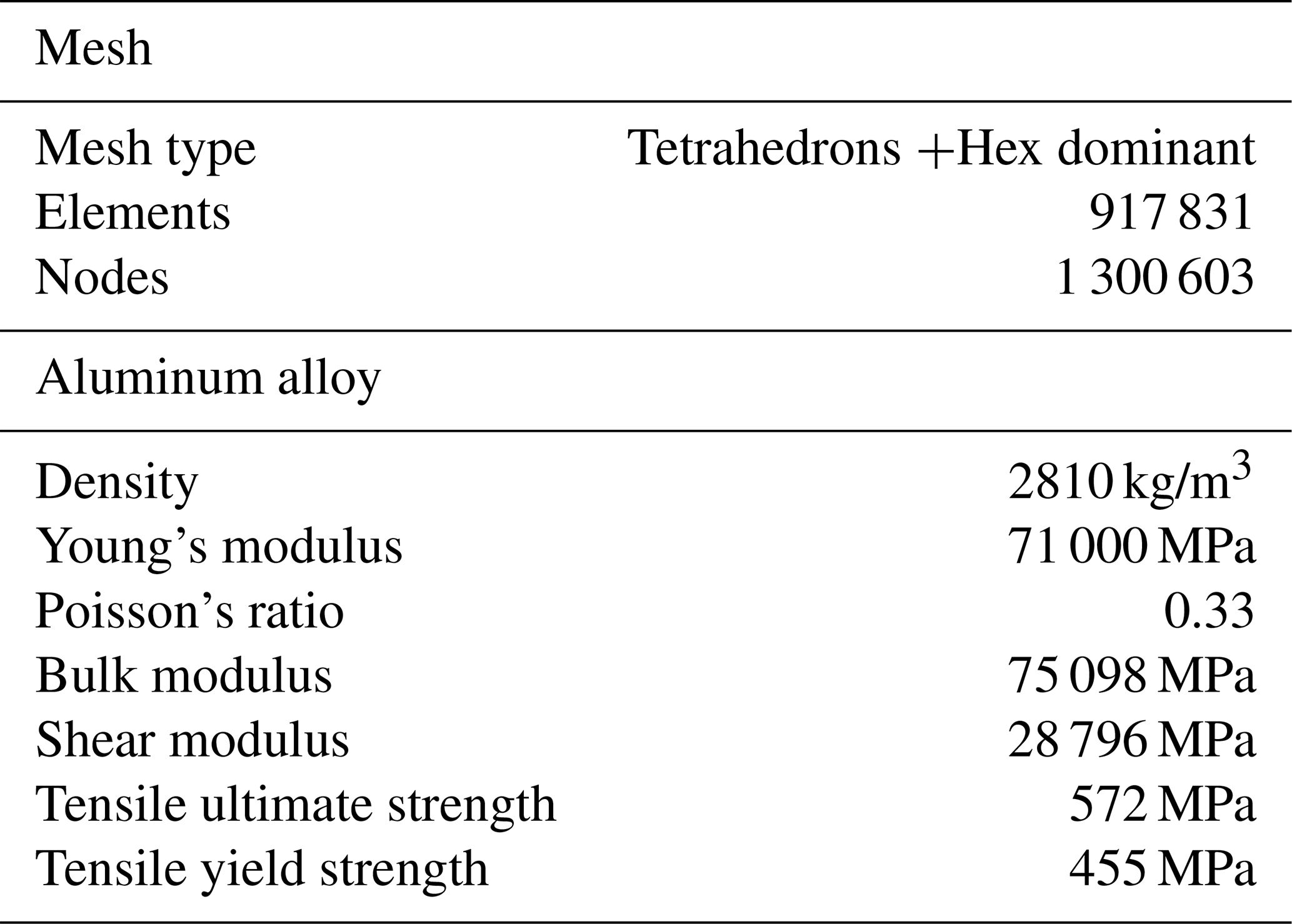
Topology optimization is a mathematical method that optimizes material layout within a given design space, for a given set of loads. Compared with conventional sizing optimization and shape optimization, topology optimization has more design freedom and can obtain extreme models, which is the most promising aspect of structural optimization. The mesh data and material properties are given in Table 2. There are in total 917 831 elements and 647 189 nodes in the discretized model.
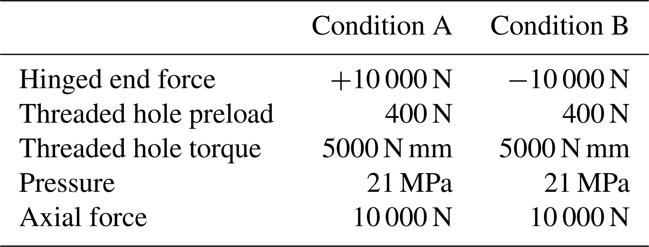
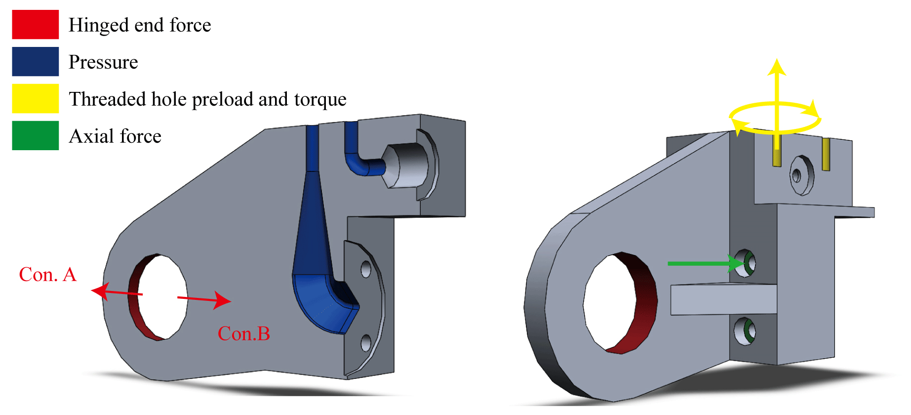
The main idea of this article is comparing and choosing the best simulation results under different working conditions. The optimized part for the manifold has two working conditions, namely pulling (condition A) and pushing (condition B): the simulation is divided into two settings as shown in Table 3. The direction of force in the table is shown in Fig. 6. The difference between the two working conditions is that the load direction of the hinged end is the opposite. The working conditions of the actuator are calculated based on the expected load demand of the whole robot. In particular, in order to ensure that the ring at the hinged end has certain strength under the condition of tension or compression, a ring with an inner diameter of 26 mm and a wall thickness of 5 mm is reserved without optimization. Between them, one condition that can meet both conditions A and B is accepted. Such operation can ensure that the topological results have certain strengths in actual working conditions.

The operating conditions settings explained next are the same in both simulations (conditions A and B). The threaded holes that fix the valve and the manifold are subjected to force and torque. There are two forces on the threaded holes: one is preload force and the other is the repulsive pressure given by the oil. In general, there is no torque in the threaded hole after installation. However, considering the bolt tightening during assembly, torque will be generated. When ignoring the torque, the model after topology will have a weak connection strength between the wall surface of the bolt hole and other areas and will deform or even break when the bolt is tightened. The part where the manifold is connected to is set as fixed, and the axial force is given at the position of the countersunk bolt hole. The axial force is determined by the bolt preload and the loading force when the system is working. Set the pressure generated under extreme working conditions in the flow channel.
The static simulation results of condition A and condition B are, respectively, optimized by the variable density method, whose penalty factor is 3. The solution methodology uses the sequential convex programming method (SPC), which is an extension of the MMA method. SPC ensures convergence by rejecting steps that do not lead to an optimal solution of the underlying problem (Zillober, 2002). Take the minimum compliance as the objective and volume percentage as the response constraint, where volume retain percentage sets the range of 20 %–40 %. According to the topology results under the two working conditions, model A and model B can be obtained, respectively. Verify the two models, respectively, under working conditions A and B, and determine which model has the ability to adapt to the changes in the actual hydraulic cylinder working conditions. Finally, the optimal model is selected as the topology optimization model.
3.3 Channel printability guarantee
According to the complexity of the optimized model, additive manufacturing (AM) should be the best processing method. Therefore, when designing the channel, special consideration should be given to the collapse of the channel printing. Because the traditional design of the channel is based on the circular section, it is bound to need support structures when being processed using AM technology. However, the support structure in the channel may have problems that are difficult or even impossible to remove.
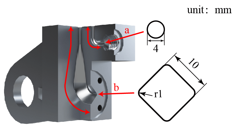
The proposed flow passage design adopts the results of our previous research; that is, the diamond-shaped channel is suitable for the AM process (Liu et al., 2019). According to the original channel size, the diamond cross-section channel is designed as having the same hydraulic diameter as the original design, and the diamond cross section is gradually changed into a circular cross section in a gradual way (shown in Fig. 7 area b). As the other flow channels conform to the maximum unsupported printing radius, the forming quality can be maintained within a reasonable range when the radius is within 2 mm (Fig. 7 area a). In addition, combined with the previous flow performance study (Liu et al., 2019), the transition between the original flow channels was vertically crossed, and now it is changed to a smooth transition to improve the flow performance.
The proposed flow passage and the original flow passage will be subjected to fluid simulation to verify the improvement of flow performance. The physical properties of the fluid medium are set to a density of 834.3 kg/m3 and a dynamic viscosity of 0.01391 Pa s. Flow rate is set to 3–15 L/min. The simulation is carried out by Fluent. Use the RNG k-e model and solve it through the simple solver. In particular, the physical properties of the flowing medium do not consider the influence of temperature during the simulation process, and the fluid–structure coupling is not used in the simulation, meaning that the interaction forces between the fluid and the wall will be ignored. More simulation settings such as mesh design can be found in the reference Liu et al. (2019).
The static simulation results of the traditional model are shown in Fig. 8. For condition A, the hinge end of the model is subject to the maximum deformation and stress, the stress is 225.35 MPa, and the maximum deformation is 0.033 mm. For condition B, the same is the maximum deformation and stress on the hinge end of the model, the stress is 179.01 MPa, and the maximum shape variation is 0.00706 mm. In the traditional model, we can find that there are many areas with small stress values, which means the traditional design model has low material utilization.
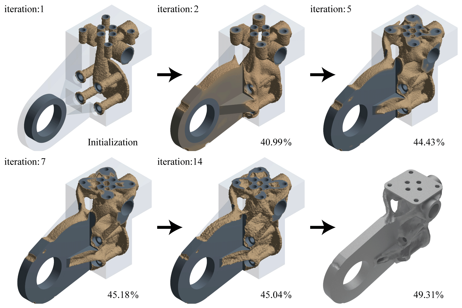
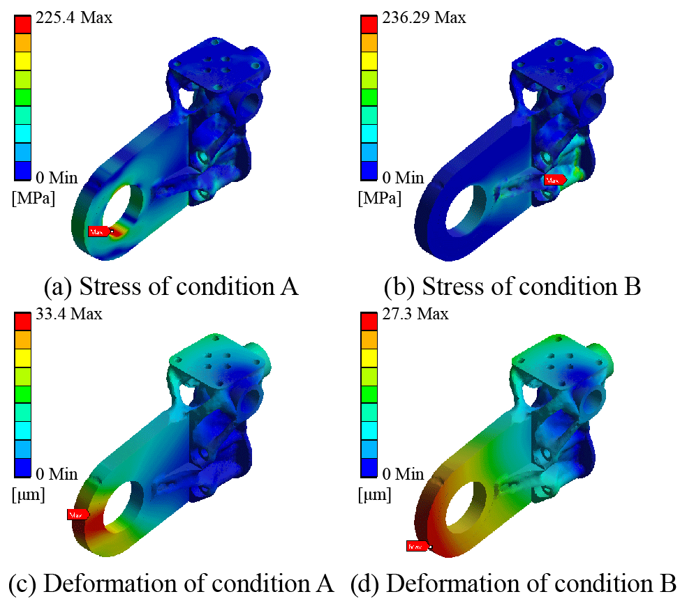
The topological optimization is carried out by using the static simulation data under condition A, and the pull model is obtained (shown in Fig. 9). The volume gradually converges with the process of topology optimization, and finally the necessary interfaces are patched to obtain the final model. The optimized model volume is 53 377 mm3. The verification results under two working conditions are shown in Fig. 10. It can be found that the maximum stress is 225.4 MPa under condition A and 236.29 MPa under condition B. Under both conditions, the safety factor is nearly 2 and can avoid mechanical failure.
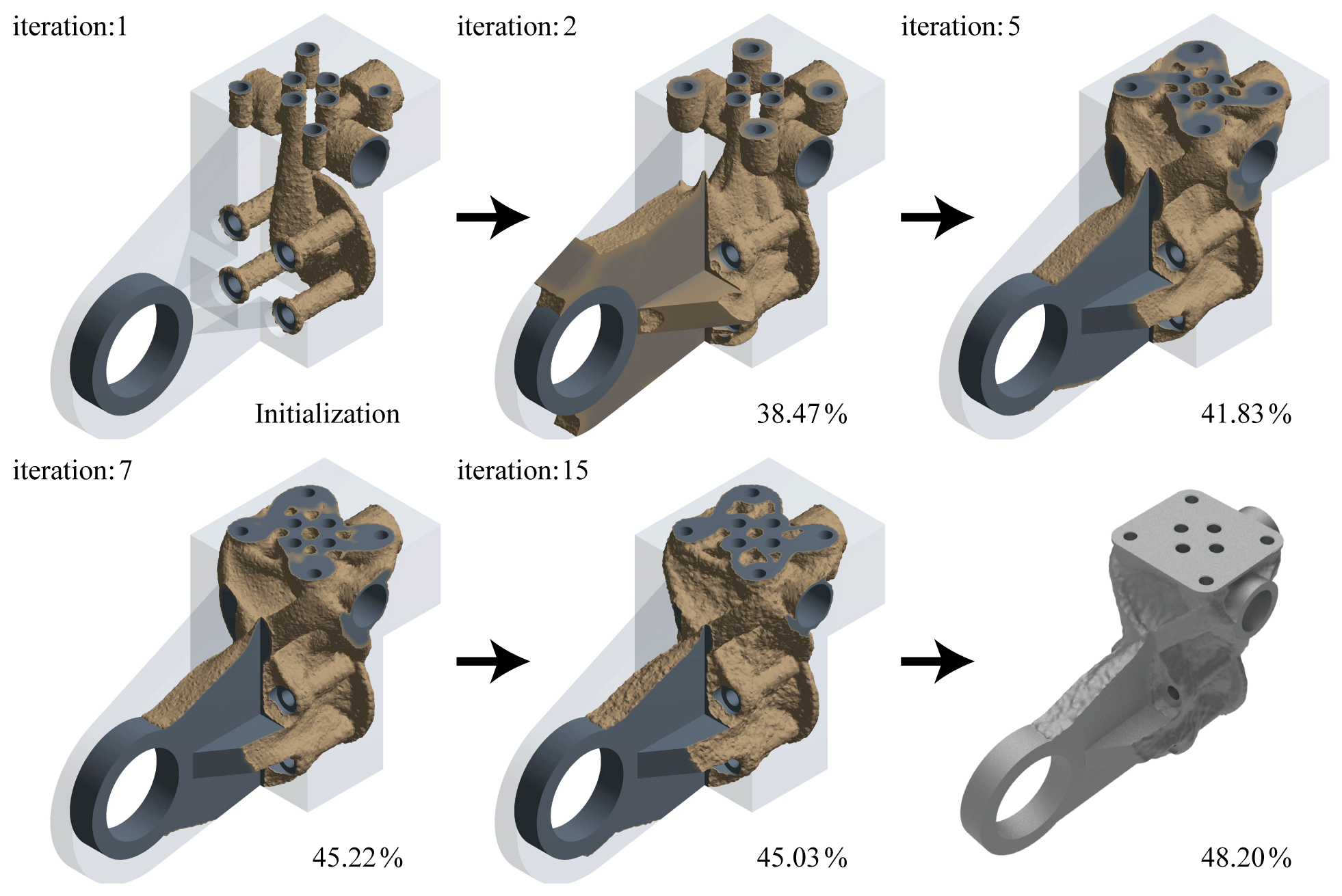
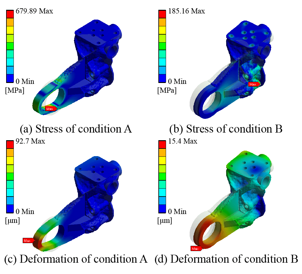
For condition B, the topological push model is as shown in Fig. 11, and the optimized model volume is 52 213 mm3. The verification results are shown in Fig. 12. It can be found that the maximum stress is 679.89 MPa under condition A and 185.16 MPa under condition B. The data of condition A show that the stress has exceeded the strength requirements, and there will be mechanical failure in use. Therefore, the topological results based on the original model simulation data of condition B cannot be used. This is because material will not be added to the reserved ring during topological condition B. Comparing Figs. 9 and 11, the clear difference can be observed in thickness of the hinged ring, which makes the push model less efficient when being pulled.
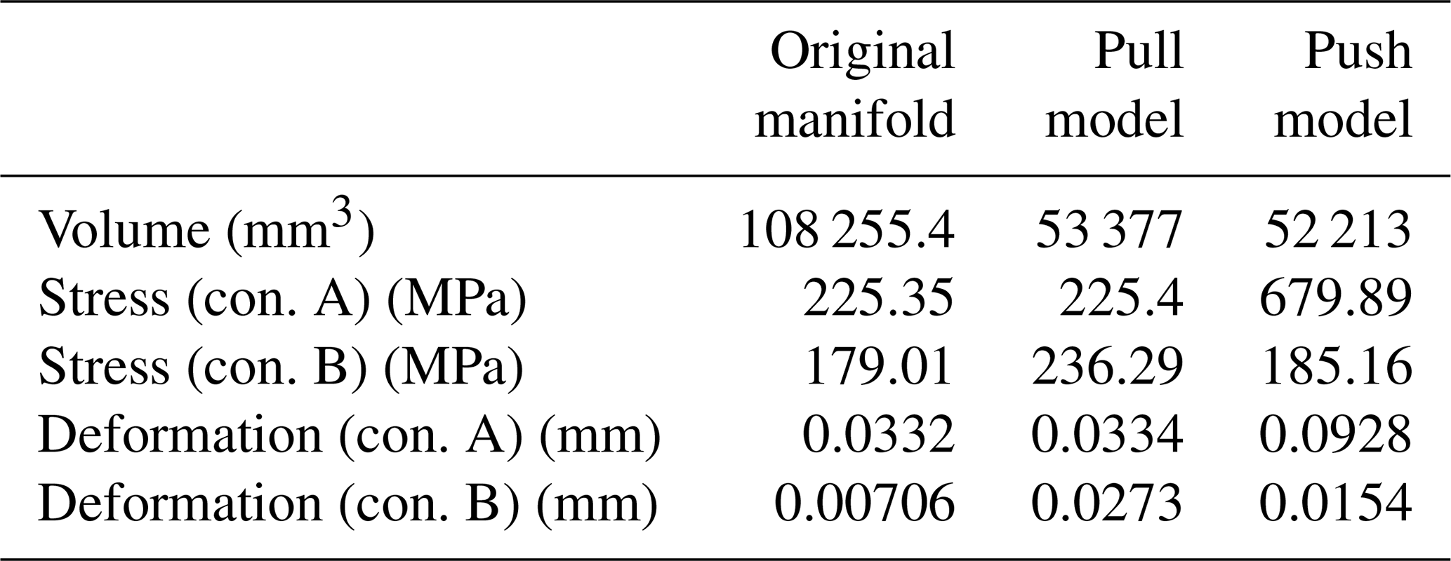
The data comparison between the models is shown in Table 4. Comparing the stress of the two models under condition A, it can be found that the pull model has smaller stress generation under the same working condition, which means the model has better stress dispersion ability and makes it more durable. However, the stress of the push model is as high as 679 MPa, which is beyond the range of material permission, and will cause safety hazards in use. Under condition B, the push model has better stress performance. Back to the practical application level, the quadruped robot will produce two kinds of working conditions when it is running, which is why we consider these two extreme working conditions when setting up the simulation.
In terms of performance on volume reduction, the pull model can reduce the volume by 50.7 % and by 51.8 % for the push model. However, generally, the overall performance of the pull model is much better, because the strength is much stronger in the pull model. It is noteworthy that the reduction of the volume is not in the range of preset 20 %–40 %: this is because the material distribution should guarantee the strength first and generate this inconsistency.
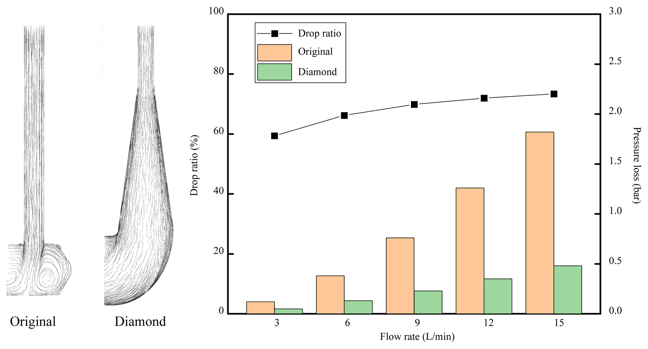
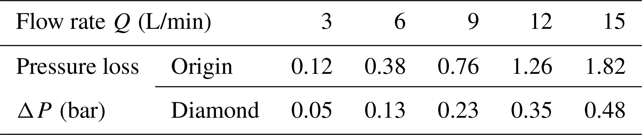
The simulation results of the channels are shown in Table 5. As the flow rate increases, the pressure loss of the two channels increases. However, compared with the traditional model, the overall pressure loss is greatly reduced by using our transitional design and diamond cross section. It can be seen from Fig. 13 that the pressure loss can be reduced by 73 % under the maximum flow. In addition, the streamline is also shown in Fig. 13. It can be seen that the original design caused a large area of vortex, which is the main reason for the greater pressure loss. This diamond-shaped transition design helps to reduce pressure loss.
This article discussed the lightweight design for manifolds mounted on the hydraulic robots. It can be seen that there is large low-stress volume, meaning these materials would not take effects.
Through the topology optimization method, the parts can be further lightened, and the model that meets the working condition requirements can be obtained so that the power-to-mass ratio of hydraulic transmission parts can be improved more.
When a part has many working conditions, the extreme working conditions should be studied to avoid failure in the performance requirements in all working conditions. In this article, the optimal result is the pull model, which can meet both the pulling condition and pushing condition.
Combined with the previous research, we proposed a diamond-shaped channel, which can ensure the forming quality of the manifold during the additive manufacturing process, and the smooth transition of the channel reduces the pressure loss by more than 50 %.
According to the design idea of additive manufacturing, it is a feasible research method to integrate the hydraulic manifold and actuator part into one part and then perform topology optimization design together to obtain lighter parts.
In the future, the authors will continue to advance relevant research, including the effect of the additive manufacturing on the performance of the entire part after post-processing, verification of the flow performance of the design channel, and finally the experimental test.
The code/data used to support the findings of this study are available from the corresponding author upon request.
HH and GL conceived the presented idea, performed the simulation and wrote the manuscript. JZ and BX provided guidance, improved the paper, and provided funding. QL and XW provided analysis for experimental data. Both the authors approved the final manuscript for publication.
The authors declare that they have no conflict of interest.
This article is part of the special issue “Robotics and advanced manufacturing”. It is not associated with a conference.
The work was funded by the Outstanding Youth Science Foundation (grant no. 51922093) and the National Key R&D Program of China (grant no. 2018YFB2000704).
This research has been supported by the National Key R&D Program of China (grant no. 2018YFB2000704) and the National Outstanding Youth Science Fund Project of the National Natural Science Foundation of China (grant no. 51922093).
This paper was edited by Guimin Chen and reviewed by two anonymous referees.
Barasuol, V., Villarreal-Magaña, O. A., Sangiah, D., Frigerio, M., Baker, M., Morgan, R., Medrano-Cerda, G. A., Caldwell, D. G., and Semini, C.: Highly-integrated hydraulic smart actuators and smart manifolds for high-bandwidth force control, Front. Robot. AI, 5, 1–15, https://doi.org/10.3389/frobt.2018.00051, 2018.
Elasswad, M., Tayba, A., Abdellatif, A., Alfayad, S., and Khalil, K.: Development of lightweight hydraulic cylinder for humanoid robots applications, Proc. Inst. Mech. Eng. Part C J. Mech. Eng. Sci., 232, 3351–3364, https://doi.org/10.1177/0954406217731794, 2018.
Hansen, M. R. and Andersen, T. O.: System topology optimization, Aust. J. Mech. Eng., 2, 133–141, https://doi.org/10.1080/14484846.2005.11464487, 2005.
Hirose, S. and Kato, K.: Study on quadruped walking robot in Tokyo Institute of Technology – past, present and future, in: Proceedings of the IEEE International Conference on Robotics and Automation, San Francisco, CA, USA, 24–28 April 2000, 414–419, https://doi.org/10.1109/ROBOT.2000.844091, 2000.
Hyon, S. H., Yoneda, T., and Suewaka, D.: Lightweight hydraulic leg to explore agile legged locomotion, in: Proceedings of the 2013 IEEE/RSJ International Conference on Intelligent Robots and Systems, Tokyo, Japan, 3–7 November 2013, 4655–4660, https://doi.org/10.1109/IROS.2013.6697026, 2013.
Khan, H., Kitano, S., Goa, Y., Caldwell, D. G., and Semini, C.: Development of a Lightweight on-Board Hydraulic System for a Quadruped Robot, in: Proceedings of the Fourteenth Sscandinavian International Conference Fluid Power, 20–22 May 2015, Tampere, Finland, 1–11, 2015a.
Khan, H., Kitano, S., Frigerio, M., Camurri, M., Barasuol, V., Featherstone, R., Caldwell, D. G., and Semini, C.: Development of the lightweight hydraulic quadruped robot – MiniHyQ, in: Proceedings of the IEEE Conference on Technologies for Practical Robot Applications TePRA, 11–22 May 2015, Woburn, MA, USA, 1–6, https://doi.org/10.1109/TePRA.2015.7219671, 2015b.
Kitano, S., Hirose, S., Endo, G., and Fukushima, E. F.: Development of lightweight sprawling-type quadruped robot TITAN-XIII and its dynamic walking, in: Proceedings of the IEEE International Conference on Intelligent Robots and Systems, Tokyo, Japan, 3–7 November 2013, 6025–6030, https://doi.org/10.1109/IROS.2013.6697231, 2013.
Kubo, S., Yaji, K., Yamada, T., Izui, K., and Nishiwaki, S.: A level set-based topology optimization method for optimal manifold designs with flow uniformity in plate-type microchannel reactors, Struct. Multidiscip. Optim., 55, 1311–1327, https://doi.org/10.1007/s00158-016-1577-0, 2017.
Li, Y., Li, B., Ruan, J., and Rong, X.: Research of mammal bionic quadruped robots: A review, in: Proceedings of the 2011 IEEE 5th International Conference on Robotics, Automation and Mechatronics (RAM), 17–19 September 2011, Qingdao, China, 166–171, https://doi.org/10.1109/RAMECH.2011.6070476, 2011.
Liu, G., Zhang, J., and Xu, B.: Structure optimization for passages in hydraulic manifolds using metal additive manufacturing technology, in: Proceedings of the 2019 IEEE 8th International Conference on Fluid Power and Mechatronics (FPM), Wuhan, China, 10–13 April 2019, 485–492, https://doi.org/10.1109/FPM45753.2019.9035877, 2019.
Meek, S., Ieee, M., Kim, J., and Anderson, M.: Stability of a trotting quadruped robot with passive, underactuated legs, in: Proceedings of the 2008 IEEE International Conference on Robotics and Automation, 19–23 May 2008, Pasadena, CA, USA, 347–351, https://doi.org/10.1109/ROBOT.2008.4543232, 2008.
Mosher, R.: Test and evaluation of a versatile walking truck, in: Proceedings of Off-Road Mobility Research Symposium, 26–27 June 1968, Washington DC, USA, 359–379, 1968.
Playter, R., Buehler, M., and Raibert, M.: BigDog, in: Unmanned Systems Technology VIII, Defense and Security Symposium, 17–21 April 2006, Florida, USA, 62302O, 2006.
Semini, C.: HyQ-design and development of a hydraulically actuated quadruped robot, PhD thesis, University of Genoa, Genoa, Italy, 210 pp., 2010.
Semini, C., Tsagarakis, N. G., Vanderborght, B., Yang, Y., and Caldwell, D. G.: HyQ – hydraulically actuated quadruped robot: Hopping leg prototype, in: Proceedings of the 2008 2nd IEEE RAS and EMBS International Conference on Biomedical Robotics and Biomechatronics, Scottsdale, AZ, USA, 19–22 October 2008, 593–599, https://doi.org/10.1109/BIOROB.2008.4762913, 2008.
Semini, C., Tsagarakis, N. G., Guglielmino, E., and Caldwell, D. G.: Design and experimental evaluation of the hydraulically actuated prototype leg of the HyQ robot, in: Proceedings of the 2010 IEEE/RSJ International Conference on Intelligent Robots and Systems, 18–22 October 2010, Taipei, Taiwan, 3640–3645, https://doi.org/10.1109/IROS.2010.5651548, 2010.
Semini, C., Tsagarakis, N. G., Guglielmino, E., Focchi, M., Cannella, F., and Caldwell, D. G.: Design of HyQ – A hydraulically and electrically actuated quadruped robot, Proc. Inst. Mech. Eng. Part I J. Syst. Control Eng., 225, 831–849, https://doi.org/10.1177/0959651811402275, 2011.
Semini, C., Goldsmith, J., Manfredi, D., Calignano, F., Ambrosio, E. P., Pakkanen, J., and Caldwell, D. G.: Additive manufacturing for agile legged robots with hydraulic actuation, in: Proceedings of the 2015 International Conference on Advanced Robotics (ICAR), 27–31 July 2015, Istanbul, Turkey, 123–129, https://doi.org/10.1109/ICAR.2015.7251444, 2015.
Simon, P.: Military Robotics: Latest Trends and Spatial Grasp Solutions, Int. J. Adv. Res. Artif. Intell., 4, 9–18, https://doi.org/10.14569/ijarai.2015.040402, 2015.
Tomlin, M. and Meyer, J.: Topology Optimization of an Additive Layer Manufactured (ALM) Aerospace Part, in: Proceedings of the 7th Altair CAE Technology Conference, 10 May 2011, Warwickshire, UK, 1–9, 2011.
Zhang, X., Zheng, H., Guan, X., Cheng, Z., and Zhao, L.: A biological inspired quadruped robot: Structure and control, in: Proceedings of the 2005 IEEE International Conference on Robotics and Biomimetics (ROBIO), 5–9 July 2005, Shatin, Hong Kong, 387–392, https://doi.org/10.1109/robio.2005.246298, 2005.
Zhu, J. H., Zhang, W. H., and Xia, L.: Topology Optimization in Aircraft and Aerospace Structures Design, Arch. Comput. Meth. Eng., 23, 595–622, https://doi.org/10.1007/s11831-015-9151-2, 2016.
Zillober, C.: SCPIP – An efficient software tool for the solution of structural optimization problems, Struct. Multidisc. Optim., 24, 362–371, https://doi.org/10.1007/s00158-002-0248-5, 2002.