the Creative Commons Attribution 4.0 License.
the Creative Commons Attribution 4.0 License.
 | 26 Feb 2021
Design and control of the belt-polishing tool system for the blisk finishing process
Cheng Fan
Caoyang Xue
Lei Zhang
Kejun Wang
Qian Wang
Yapeng Gao
Lei Lu
According to the structural characteristics of the blisk, a new adaptive belt tool system for blisk finishing is developed. The pneumatic servo system, which is composed of the cylinder, the servo valve, and the force sensor, is used to control the polishing force. Due to the strong nonlinearity of the pneumatic system, a two-dimensional fuzzy proportion, integral, derivative (PID) controller is developed for the pneumatic force control. The proposed controller adjusts the proportional, integral, and differential parameters of the traditional PID controller in real time through the error and error rate so as to optimize the control performance of the pneumatic system. Compared with the PID control, the steady-state error of the fuzzy PID control is reduced by 0.03 s and the overshoot is reduced by 4 %, which reveals the superiority of the fuzzy PID control algorithm for the nonlinear system. Finally, the experiments of polishing the blisk sample and the real blisk are carried out by the proposed belt tool system. The results show that the polishing process is very stable and the roughness after polishing is less than 0.4 µm, which proves the effectiveness of the proposed new belt tool system and the fuzzy PID controller.
- Article
(5315 KB) - Full-text XML
- BibTeX
- EndNote


An aeroengine is the heart of aircraft, known as “the bright pearl on the crown of industry”. The thrust–weight ratio and the fuel consumption rate are the comprehensive indicators to measure the technical level and the working ability of the aeroturbine engine. Improving the thrust–weight ratio of the aeroengine is the core task for the modern aeroengine structure design and manufacturing. Since the mid-1980s, developed countries have adopted the blisk structure in the new aeroengine design. It represents the development direction of high thrust–weight ratio technology for the fourth- and fifth-generation aeroengines and has become the necessary structure of the aeroengine technology. The blades and the impeller of the integral blisk are designed as a whole. Compared with the conventional assembled blisk, it has the following advantages: (1) the connection structures such as blade tenon and tenon groove are omitted to reduce the weight of the fan rotor and compressor rotor; (2) the flow path at the blade and root is not interrupted, which helps to reduce the loss of wind resistance; (3) the temperature of the compressor rotor is reduced, which helps to improve rotor life; (4) the connection parts such as the bolts, nuts, and locking plates are omitted, and thus the potential faults such as the damage and the fracture of the mortise and the groove are avoided and the reliability is improved. When the integral blisks are used, the weight of the aeroengine can be reduced by 20 %–30 %, the efficiency can be increased by 5 %–10 %, and the number of parts can be reduced by more than 50 % (Zhang et al., 2017). Because of its outstanding advantages, the blisk is regarded as the core component of the next generation of the aeroengine to achieve functional leap-forward development and technical improvement.
The blade on the integral blisk is thin and deformable, and the profile of the blade is complex. The materials of the blisk are generally titanium alloy or high-temperature alloy, which are difficult to process. As a result, the precision manufacturing of the integral blisk is very challenging. The manufacturing process of the blisk can be divided into three stages, which are forming, finishing, and strengthening. In the forming stage, the initial forming of the blisk is mainly completed by the casting, forging, or linear friction welding. Then, the blade is further processed by milling and electrochemical machining. In the finishing stage, the defects such as the milling marks and the electric erosion layer are removed by hand grinding and polishing so as to improve the surface roughness and surface accuracy of the blisk blade. Finally, the strengthening treatment is carried out by the shot-peening process. Many scholars have done a lot of research on the numerical control (NC) milling, the electrochemical machining, the linear friction welding, and other processing technologies of the blisk (Chen et al., 2016; Raab et al., 2015; Ren et al., 2004).
The finishing process of the integral blisk can further improve the surface roughness and surface form accuracy after computerized numerical control (CNC) milling or electrochemical machining so as to improve the air flow channel and the fuel efficiency and achieve the purpose of improving the fatigue strength and extending the service life of the blisk. The finishing methods of the blisk include the belt polishing, the elastic wheel polishing, and the abrasive flow polishing. In the abrasive flow-polishing process, the viscoelastic body containing a soft abrasive medium is extruded through the surface to be machined repeatedly and finally realize the surface finishing. The abrasive flow-finishing technology has obvious advantages in the machining of the parts with complex shape and inner cavity, which is hard to reach and contact by the general tools (Singh and Shan, 2002; Zhao et al., 2020). The abrasive flow-finishing process was used by Dynatics Co. Inc. in the United States to polish the blisk of a space aeroengine after NC milling. It removes the surface cracks and the residual stress, which solves the fracture problem that often occurred in the process of high-speed rotation of the blisk (Zhang et al., 2004). Fu et al. (2016) developed the experimental platform for the abrasive flow polishing of the blisk. The simulation mechanical model of the abrasive media extrusion flow field and the simulation model of the core mould with or without drainage were established. They compared and analyzed the distribution of the flow field of the two models and optimized the fixture structure to achieve uniform finishing of the spiral surface. Based on the analysis of the polishing on the blade tip, airfoil, edge, and runner surface, Huang et al. (2014) and Xiao and Huang (2015, 2016) developed a CNC belt-grinding machine tool of seven axes and the abrasive belt-grinding tool system to polish the blisk. The non-interference movement of the grinding tool was analyzed. Zhao et al. (2014) and Chen et al. (2018, 2019) used the method of a “five axis numerical control + flexible polishing head + elastic abrasive tool” to carry out the self-adaptive polishing of the blisk. They developed the flexible polishing spindle and studied the trajectory planning, the interference analysis, and the optimization of process parameters during the polishing of the blisk. In earlier research by Zhang et al. (2020), the algorithm for judging the critical interference is proposed based on the structural characteristics of the abrasive belt tool system and the actual grinding and polishing process of the blisk.
Polishing force plays an important role in the surface roughness and the material removal after polishing (Fan et al., 2019a). When the blisk is polished with belt tools, the polishing sliding speed and polishing contact force play an important role in the surface roughness. The contact force during polishing needs to be controlled (Zhu et al., 2018). Chen et al. (2019) presented a novel smart end effector for active contact force control and vibration suppression in robotic polishing of thin-walled blisks. A gravity-compensated force controller was developed to maintain the contact force between the polishing tool and the workpiece to an expected value. Xiao and Huang (2015) developed constant-load adaptive belt polishing for the thin-walled weak-rigidity blisk blade to improve the dimensional precision and surface quality. The motion mechanism and control model for the micro-displacement during the polishing were analyzed and optimized. The research of force control in the process of the blisk polishing is still in the experimental stage.
In this paper, a new adaptive belt tool system is specially designed for polishing the blisk. The advantage of the proposed system for the polishing of the blisk is presented and analyzed. Due to the disadvantage of the PID control for a nonlinear pneumatic system, a fuzzy adaptive PID control system for polishing force is established. The overshoot, stability error, and adjustment time of the algorithm are analyzed by experiments. The superiority of adaptive fuzzy PID control for a pneumatic servo system is proven. Section 2 introduces the structure and pneumatic control method of the belt tool system. Section 3 introduces the design of an adaptive fuzzy PID controller. In Sect. 4, the effectiveness of the belt tool system and control algorithm is verified by experiments. Conclusions are presented in Sect. 5.
2.1 The structure of the belt tool system
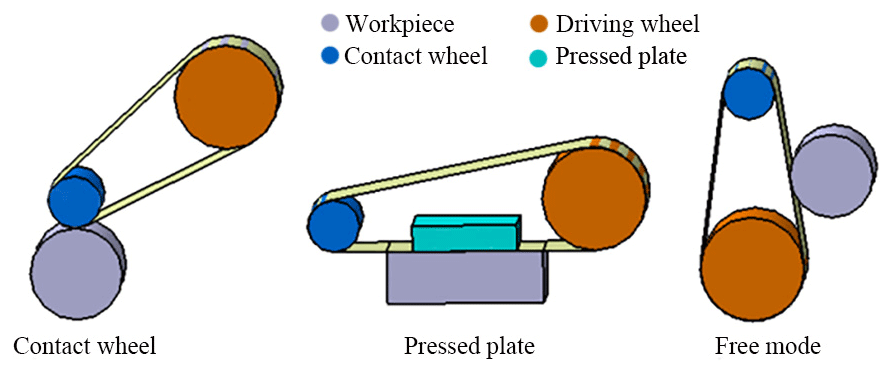
As shown in Fig. 1, the belt-polishing process can be divided into three different kinds considering the ways that the belt fits the workpiece, which are belt polishing with the contact wheel, polishing with a pressed plate, and free-mode belt polishing. As shown in Fig. 1b, the pressed plate is used to increase the contact pressure during the polishing, and it is more suitable to grind the flat workpiece. As shown in Fig. 1c, in free-mode belt polishing, the belt contacts with the workpiece directly, which provides the compliance belt–workpiece contact because of the self-flexibility of the belt. As a result, the free-mode belt polishing can adapt to the contour of the workpiece within a certain range. Compared with the other two methods, the belt polishing with the contact wheel is the most widely used, which is often used to finish the cylinder, hole, flat plane, and curved surface. The blade of the blisk contains the convex and concave surfaces. When the tool polishes the inner convex surface of the blade, the belt must be supported to press the blade surface. Thus, the contact wheel is needed to fit the belt on the convex surface. Therefore, the belt-polishing tool system designed in this paper adopts the contact wheel to contact with the blade surface.
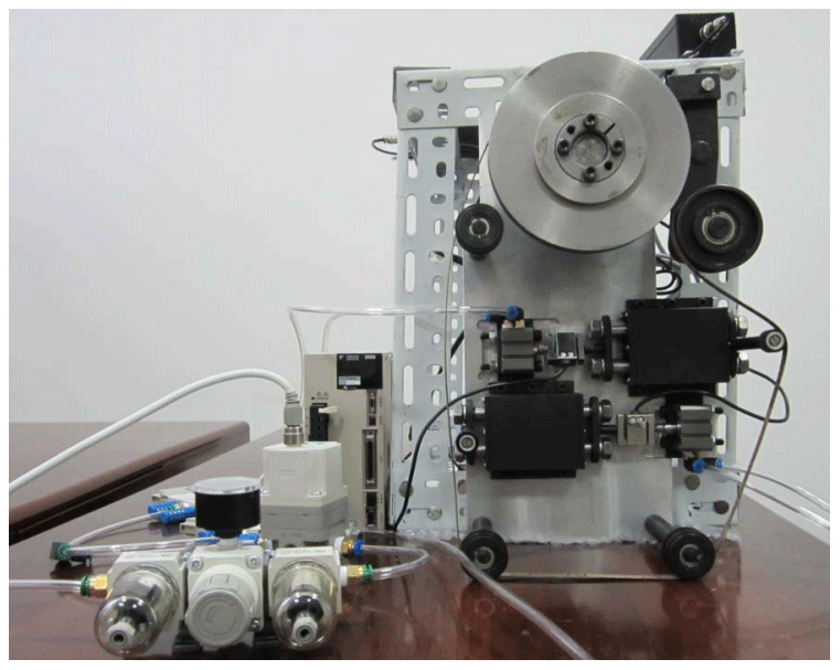
The adaptive belt tool system is composed of the belt, the drive mechanism, the tension mechanism, the contact mechanism, and other necessary components. As shown in Fig. 2, the belt tool system designed for the blisk polishing in this paper includes two parts, which are the polishing tool subsystem and the constant force control subsystem. In addition to the necessary driving wheel, tension pulley, and contact wheel, there are three idler wheels in the gear system supporting the belt. Each wheel supports the belt into a special structure according to a certain position. As a result, the different wrap angles can be generated at the two contact wheels, respectively, to avoid the interference. In order to reach the blade root, all wheels are installed on the base plate through the cantilever shaft. The two contact wheels are arranged in two sides with the opposite directions. The side with a large wrap angle is used for polishing the concave side of the blade, while the side whose belt is straightening and without a wrap angle is used for polishing the convex side. The cylinder connected with the contact wheel is used to adjust the polishing normal force, and the force sensor is used as a feedback. The assembled belt tool system is shown in Fig. 3.
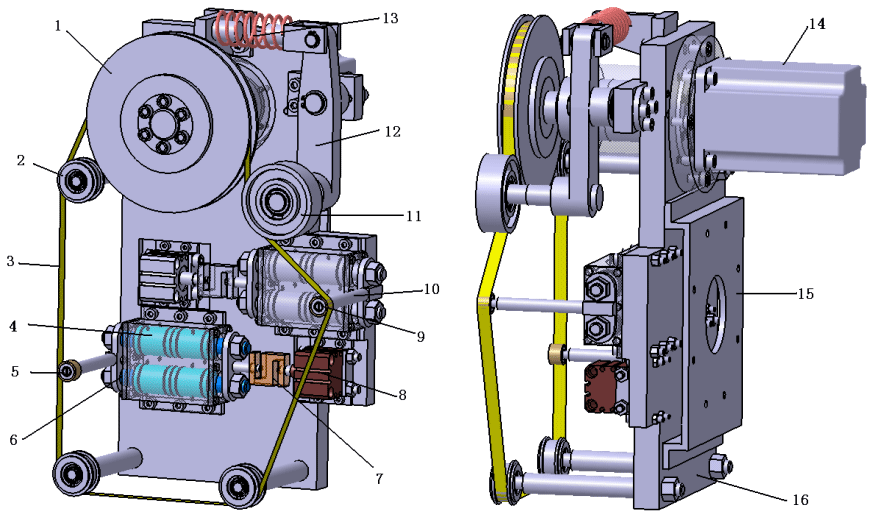
Figure 2Structure drawing of the belt tool system. (1) Driving wheel. (2) Idler wheel. (3) Belt. (4) Linear bearing. (5) Contact wheel on the convex blade side. (6) Linear optical shaft. (7) S-shaped force sensor. (8) Cylinder. (9) Contact wheel on the concave blade side. (10) Shaft of the contact wheel. (11) Tension pulley. (12) Tension arm. (13) Tension compression spring. (14) Drive motor. (15) Flange. (16) Substrate for installation.
The tool system designed in this paper has the following structural features.
-
Through the reasonable setting of the location and size of the idler wheel, the belt is supported into a special structure, which can produce a suitable wrap angle at the contact wheel to adapt to the change in the curvature of the blade surface.
-
According to the difference between the convex and concave surfaces of the blade, two contact wheels arranged alternately can be used to grind and polish the convex and concave surfaces of the blade, respectively, so as to avoid the large angle swing of the tool system during the polishing process.
-
In order to polish the blade with constant force, the low-friction cylinder was adopted and the force sensor is used to measure the normal force in polishing.
-
This structure of the belt tool system is compressed with the size of 360 mm × 230 mm only. This system is light, less than 20 kg. Therefore, the belt tool system is economical, practical, and easy to install.
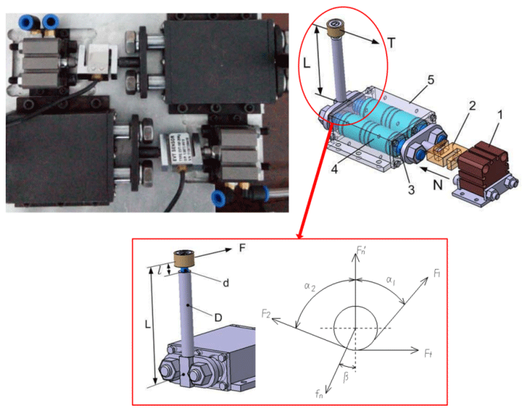
Figure 4Structure diagram of force control. (1) Low-friction cylinder. (2) S-shaped force sensor. (3) Linear optical shaft. (4) Linear bearing. (5) Bearing block.
As shown in Fig. 4, the force control system includes a low-friction cylinder, an S-shaped high-precision force sensor, a pair of linear optical shafts, and a pair of linear bearings. Because the cylinder output shaft and the contact wheel are not in the same straight line, the linear optical shafts and the linear bearings are not only used to reduce the friction in the process of force transmission, but also to overcome the torque T which is indicated in Fig. 4. During the polishing, the direction of the cylinder output shaft, which is also the direction of the cylinder output force, will be in the same straight line with the normal direction at the polishing point. The output force of the cylinder is not only used to generate the normal force of the polishing, but also to offset the force exerted on the contact wheel when the belt is tensioned. As indicated by Fig. 4, the contact force during the polishing can be expressed as
where N is the output force of the cylinder, F1 and F2 are the tension force on the belt, α1 is the included angle between F1 and , and α2 is the included angle between F2 and .
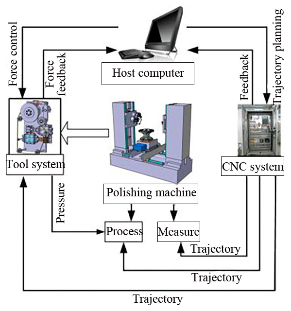
As shown in Fig. 5, the adaptive belt tool system is installed on the five-axis horizontal machine tool. The machine tool provides the five motion axes required for polishing operation, including the translation axes x, y, and z and rotation axes b and c. The belt tool system is installed on the column of the z axis through the rotary table of the b axis. The blisk is installed on the rotary table of the c axis, and the rotary table of the c axis is installed on the x axis and y axis. During the polishing process, the b axis is rotated to ensure that the cylinder output shaft pushes the contact wheel to move along the normal direction of the blade all the time. Figure 6 describes the state of the belt tool system when polishing the convex and concave surfaces. When the blisk rotates around the c axis, one contact wheel can be used to grind and polish the concave side of all the blades along the same tool path, and the other one can be used to grind and polish the convex side. The blisk does not need to be turned over and the tool system does not need to rotate a lot. Therefore, the polishing of the blade surface can be completed easily.
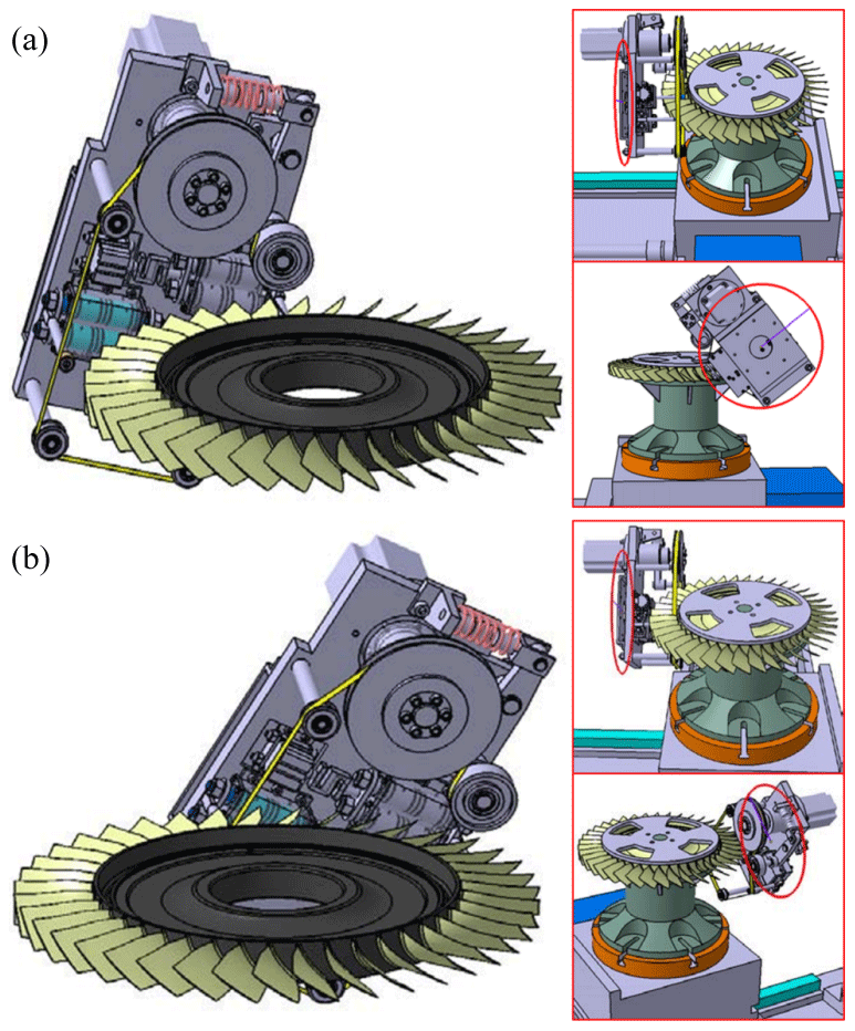
Figure 6Drawing of the polishing concave side and convex side: (a) polishing the concave side of the blade and (b) polishing the convex side of the blade.

2.2 Pneumatic control scheme of the belt tool system
Two sets of the independent pneumatic system are used for the constant contact force control during the polishing of the concave and convex surfaces of the blade. Each system includes the PC machine (controller), the data acquisition card, the pneumatic proportional servo valve, the force sensor, the cylinder, and the rodless cylinder. The rodless cylinder is used to control the tension force of the belt through the pressure-regulating valve. At the same time, it is used to control the tension and release of the belt. The force sensor collects the signal of the contact force during the polishing and transmits it to the controller through the data acquisition card. Then the set value of the polishing force is compared with the actual collected value. The polishing force signal calculated by the controller is output to the pneumatic proportional valve through the data acquisition card so as to control the output force of the cylinder, finally achieving the dynamic balance between the actual polishing force and the set value.
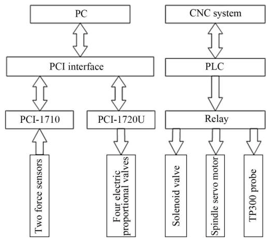
As shown in Fig. 7, the compressed air from the air source is filtered by the pneumatic triplet and enters into both sides of the thin cylinder. The force sensor is connected with the piston of the cylinder. The given constant polishing force corresponds to the signal Ug. The host computer controls two pneumatic electric proportional valves through conversion to generate a pressure difference on both sides of the cylinder piston. The output force is produced by the pressure difference. At this time, the force sensor will generate a force signal. The measured force signal will be amplified by the amplifier and the conversion performed by the data acquisition card. The measured voltage Uf corresponds to the actual contact force. Finally, comparing Uf with Ug, the controller in the PC machine adjusted the output signal. As shown in Fig. 8, the electric control system of the belt tool system is based on the PC machine and CNC system. PC is connected with the data acquisition card through the PCI interface. PCI-1710 receives the analog inputs of two force sensors and transmits them to PC. The output signal is transmitted to the pneumatic servo valve through the PCI-1720u control card. As shown in Fig. 8, the polishing spindle in the belt tool system is controlled by the CNC through the intermediate relay.
The PID controller has a better control effect for the system with known model and constant parameters. Due to the nonlinearity of the pneumatic system and the disturbance of the external environment, the dynamics performance of the pneumatic force control system will change. Different polishing forces may correspond to different PID parameters. As a result, the PID parameters have to be readjusted again when the polishing condition changes, which seriously affects the polishing efficiency (Fan et al., 2019b). Therefore, a self-tuning PID algorithm is needed to realize the real-time self-tuning of PID parameters so as to improve the processing efficiency. This paper realizes the real-time adaptive control of polishing force based on the fuzzy PID controller.
3.1 Fuzzy PID controller design
The fuzzy self-adaptive PID system is mainly composed of PID tuning and fuzzy reasoning. For PID tuning, the outputs of the fuzzy reasoner are generally ΔKp, ΔKi, and ΔKd, and the inputs are generally the error of system feedback, the rate of error change, and the rate at which the error changes. As shown in Fig. 9, the two-dimensional fuzzy controller is used in this paper, which takes the error and the error rate of change as the input to control the PID parameters.
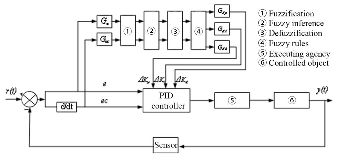
It can be seen from Fig. 9 that the adjusted PID parameters can be expressed by
3.2 Design of fuzzy rules
The input and output of the computer are precise quantities, while the fuzzy quantities can only be accepted by the fuzzy controller. Thus the precise quantities must be fuzzed. In this paper, the fuzzy set of the precise quantities is divided into seven language variables: [Negative Big, Negative Middle, Negative Small, 0, Positive Small, Positive Middle, Positive Big], which can be recorded as [NB, NM, NS, O, PS, PM, PB]. The meaning of these letters are as follows. N: Negative, B: Big, M: Middle, S: Small, O = 0, P: Positive.
3.2.1 Universe and basic universe
The actual ranges of the input and output variables e, ec, and control quantity U of the fuzzy controller are called their basic universe. Suppose that the basic universe of error, error rate ec, and control quantity U are [], [−xe, +xec], and [−xu, +xu], respectively, then the universe of the fuzzy subset of error e is
The universe of the fuzzy subset of error rate ec is
The universe of the fuzzy subset of control quantity U is
where n, m, and 1 are the numbers divided after discretization in their respective universe. The basic universe is determined according to the specific system output and experience. Generally speaking, the universe can be set as []. The quantitative factors of the error and the error rate are expressed as [], respectively, and the scale factor of the control quantity is expressed as [].
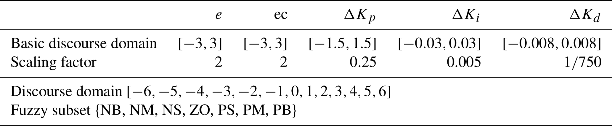
It can be seen from Fig. 7 that the input and output of the pneumatic servo system are the voltage. Since the tension force needs to be overcome during the polishing, the initial input voltage of the pneumatic servo system is set as 3.5 V. The voltage is increased on this basis during polishing; thus, the variation range of voltage error e is set as []. When the voltage changes again within the range, the variation range of error ec can be observed by the oscilloscope, which is []. As shown in Table 1, the ranges of ΔKp, ΔKi, and ΔKd can be obtained from continuous test and comparison successively.
3.2.2 Selection of membership function
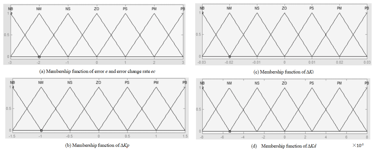
The membership function is the characteristic function of a fuzzy set, which represents the degree of a certain precise quantity to the fuzzy set. A membership function is also a mapping from the fuzzy set to the [0,1] interval. With the shape curvature of the membership function increasing, the resolution and control sensitivity are improved. By contrast, the smaller the curvature, the gentler the control characteristics and the better the stability of the system. In engineering application, the triangle membership function is generally used, which is easy to calculate and has a low memory footprint. The triangle membership function is suitable for online adjustment of the adaptive control system because of its large curvature change in the function shape, high resolution, and sensitivity. The universe of the triangle membership function is also set as []. As shown in Fig. 10, the membership function diagrams of error e, error rate ec, ΔKp, ΔKi, and ΔKd can be drawn through MATLAB.
3.2.3 Setting of fuzzy control rules
For the conventional PID control, when the integral coefficient increases, the system response becomes fast, but the overshoot is large. When the differential coefficient increases, the system stability is good and the overshoot is small, but the anti-interference ability is low. Therefore, the following setting rules are obtained for e and ec in the different conditions.
When the deviation error is large, the proportional coefficient Kp should be increased to make the system have fast response ability. The differential coefficient Kd should be reduced to prevent a differential saturation phenomenon, and the integral coefficient Ki is set as 0 to prevent large overshoot.
When the deviation errors and are appropriate, Kp should be reduced, and Ki and Kd should not be changed.
When the deviation error is small, Kp and Ki should be increased to enhance the stability of the system to avoid concussion. The value of Kd depends on . When is small, Kd should be adjusted larger. By contrast, when is large, Kd should be adjusted smaller.
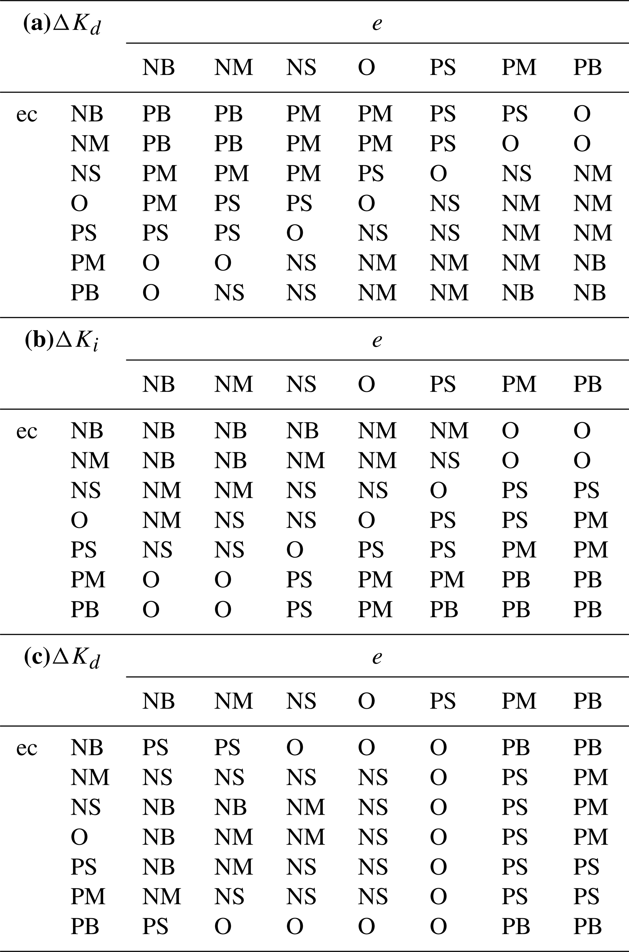
The establishment of fuzzy rules should ensure that the cylinder can smoothly output the polishing force, and the entire system should remain stable. The establishment of fuzzy rules often uses the conditional statement “IF A AND B THEN C”. The fuzzy control rules of the proposed controller are shown in Table 2.
Table 2Rule table of fuzzy control. (a) Fuzzy rule table of ΔKp. (b) Fuzzy rule table of ΔKi. (c) Fuzzy rule table of ΔKd.
3.2.4 Fuzzy reasoning and defuzzification
After the establishment of the fuzzy rules, it is necessary to carry out the fuzzy reasoning calculation. There are many different algorithms for the fuzzy reasoning, including the fuzzy reasoning algorithms of Mamdani, Larsen, and Takagi and Sugeno. In this paper, the Mamdani-type fuzzy reasoning algorithm is used.
The defuzzification is also needed. The result of the fuzzy reasoning is a fuzzy value, which needs to be transformed to be recognized by the system. The process of the defuzzification can be regarded as a kind of mapping from the fuzzy space to the precision quantity space. At present, the methods of centroid, bisector, mom (average maximum membership method), lom, and som (the method of taking the maximum and the minimum in the maximum membership function) are commonly used. The centroid method is used in this paper.
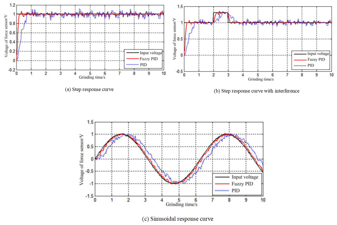
In this paper, the control algorithm is verified by the polishing experiment. Firstly, the polishing force control experiment is carried out under the condition of no rotation of the polishing wheel. In the experiment, the polishing time is set as 10 s and the sampling period is 50 ms. The reference signal is, respectively, step signal, step signal with interference, and sine signal with an amplitude of 1. The output voltage is shown in Fig. 11. As shown in Fig. 11a, the adjustment time, steady-state error, and overshoot of fuzzy PID response are 9.95 s, 0.0834 s, and 9.92 %, respectively. Compared with PID control, the steady-state error is reduced by 0.03 s and overshoot is reduced by 4 %. As shown in Fig. 11b, when an interference signal lasting for 1 s is added, the response speed of fuzzy PID control is faster than PID control. As shown in Fig. 11c, both the red curve and the blue curve lag behind the input signal, but the red curve can always trace the input signal quickly, which means the control accuracy of the fuzzy PID control is better than PID control.
From the above analysis, it can be seen that the system with an accurate model can be controlled by the PID controller accurately. However, the pneumatic servo system exhibits high nonlinear characteristics, such as the compressibility of air, the complexity of the friction force, and the dead-zone effect, which will cause noticeable variations of the parameters of the system. Thus, for the pneumatic system with an imprecise mathematical model, the fuzzy PID control is more accurate and the response speed is faster.
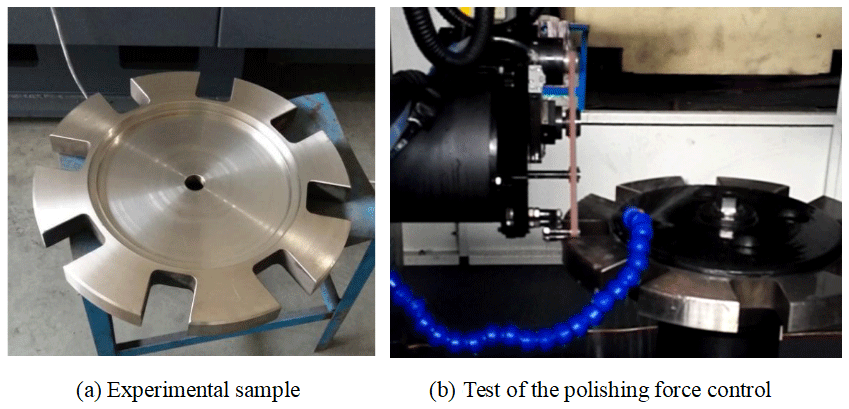
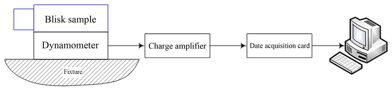
Then, the stability of the belt-polishing system and the force control system is tested in the actual polishing process. The blade of the blisk is a free-form surface. When the real blade of the blisk is polishing, the direction of the polishing force changes with the change in the blade surface. If the actual blade is used, the direction of the polishing force cannot be determined, so that the force-measuring instrument cannot be positioned and installed. In order to facilitate the measurement of the polishing force, a new kind of blisk sample is designed which is shown in Fig. 12a. The overall size of the sample is the same as the real blisk. Each blade profile is perpendicular to the horizontal plane; thus, the direction of the polishing force is parallel to the ground. As a result, the real polishing force can be measured by the dynamometer, as shown in Fig. 13.
As shown in Fig. 13, a Kistler piezoelectric dynamometer (9257B series) is used for measuring the polishing force. The charge generated by the dynamometer is converted into a voltage signal (0–10 V) by a 5017B charge amplifier and transmitted to a data acquisition card. The host computer realizes the real-time display of the polishing force value.
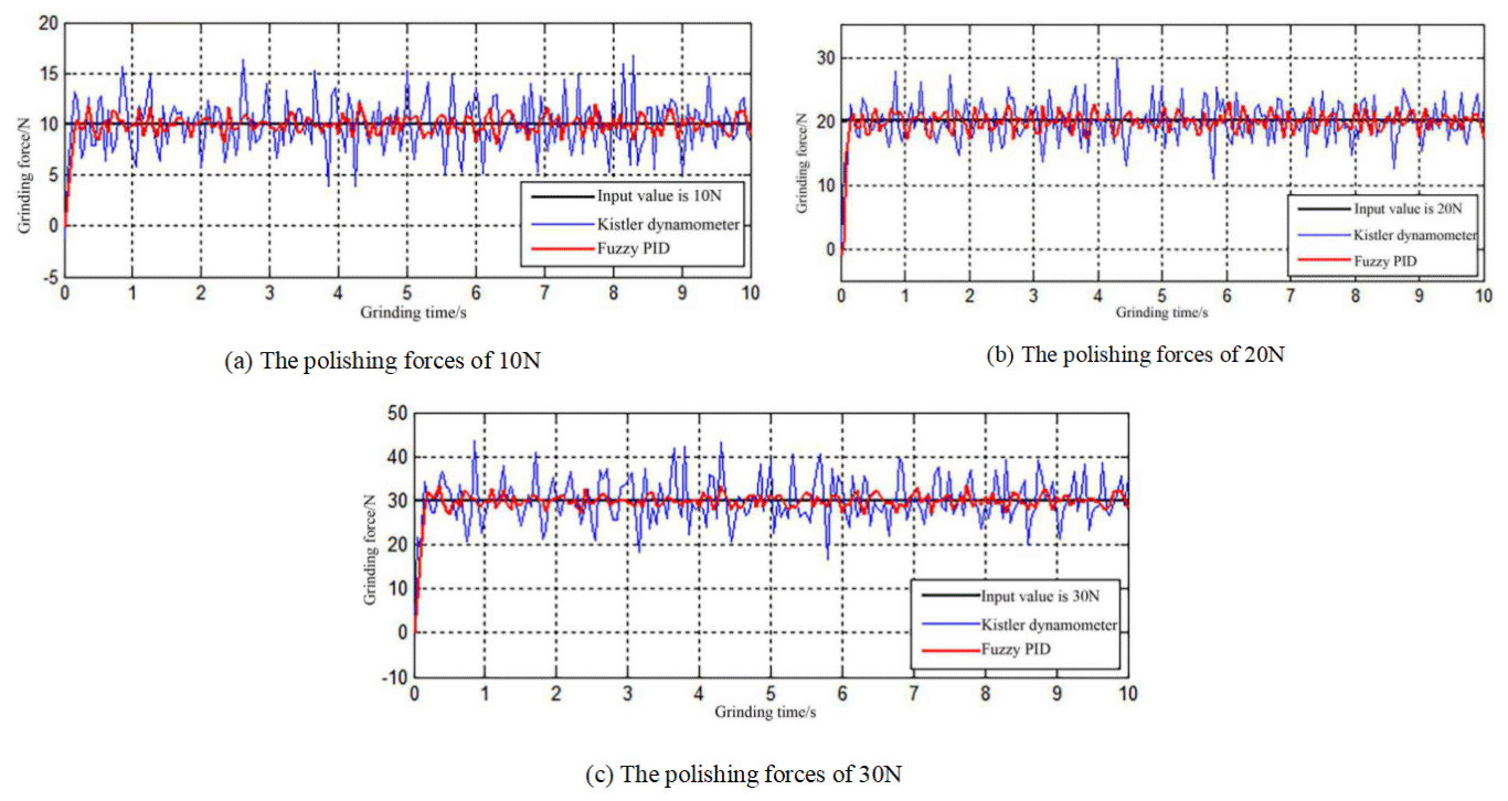
In the experiment, the air source pressure was set as 0.9 Mpa. The German VSM stacking abrasive belt KK712X was used. The size of the belt was 9×1005 mm, and the particle size was P600. The spindle speed was set as 3000 r/min. The sampling period was 50 ms, and the sampling time was 10 s. The tension was set as 50 N. In the experiment, the PID parameters were, respectively, 0.234, 0.211, and 0.0297. The polishing forces of 10, 20, and 30 N were given, respectively, to measure the value of the actual polishing force.
Three groups of experimental results are shown in Fig. 14. The measurement results of the Kistler force-measuring instrument are always larger than that of a fuzzy PID controller. The signal of the fuzzy PID is collected from the S-shaped force sensor (as shown in Fig. 4). This is because the measurement results of Kistler include the influence of the vibration of the machine tool and external environment. With the increase in the setting value of the polishing force, the fluctuation range of the actual value becomes larger. The fluctuation range of the polishing force is maintained at [] when the polishing force is 10 N, [] at 20 N and [] at 30 N. However, no matter how big the force is, it can track the error well and adjust it in time, which proves that the control of the fuzzy PID algorithm has an obvious effect.
The surface of the sample after polishing is shown in Fig. 15. Figure 15a shows the surface profile of the experimental sample before polishing. The machined surfaces when the polishing forces are 10, 20, and 30 N, respectively, are shown in panels (b), (c), and (d).
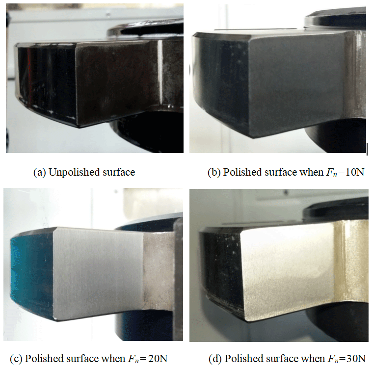
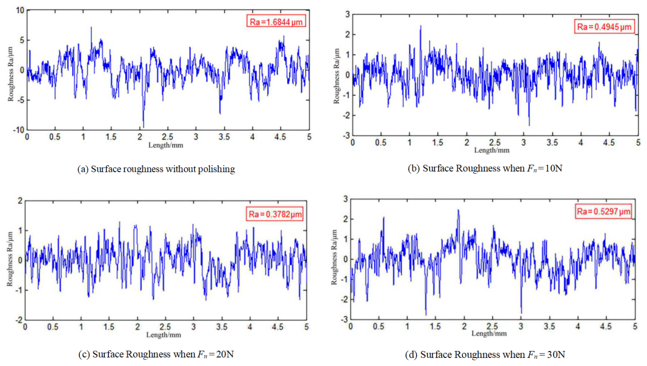
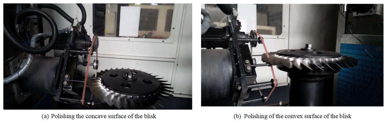
The surfaces in Fig. 15 were measured by the MarSurfM300C portable roughness-measuring instrument made in Germany. The measurement length is 5 mm. The results are shown in Fig. 16. As shown in Fig. 16a, the average roughness of the unpolished surface is 1.6844 µm. It can be seen that the machined surface is not uniform. Figure 16b, c, and d are the roughness values after the polishing when the contact forces are 10, 20, and 30 N, respectively. The average roughness values are 0.4945, 0.3782, and 0.5297 µm, respectively. The roughness changes of the three are relatively uniform. Among them, polishing at 20 N has the best finishing effect, meeting the requirement of roughness Ra < 0.4 µm, which is also the standard of roughness for the real blisk. When Fn=10 N, the contact force is too small, which leads to the original surface not being completely polished; thus, the roughness is large. When Fn=30 N, the contact force is too large, which will cause the vibration of the belt system and the machine tool; thus, the measured roughness is relatively large. As shown in Fig. 17, the experiment of polishing the real blisk is carried out using the proposed belt tool system. Figure 17a and b correspond to the polishing of the concave and convex surfaces of the blisk. In the experiment, the polishing force is set as 20 N during the whole polishing procedure. Finally, the average surface roughness is less than 0.4 µm, meeting the finishing requirement of the blisk.
According to the features of the concave side and the convex side of the integral blisk, a belt tool system is designed to polish the blisk. The belt tool system consists of two parts, which are the polishing tool subsystem and the constant force control subsystem. The polishing tool subsystem controls the polishing sliding speed by the servo motor, while constant force control is achieved by the pneumatic servo. In order to overcome the shortcomings of traditional PID control, an adaptive fuzzy PID controller is designed in this paper. The experiment shows that the fuzzy PID controller responds fast and can realize the real-time control of the pneumatic polishing force. Compared with PID control, the steady-state error of an adaptive fuzzy PID controller is reduced by 0.03 s, and the overshoot is reduced by 4 %. The experimental sample of the blisk is polished when Fn is set as 10, 20, and 30 N. The results show that the average roughness is 0.4945, 0.3782, and 0.5297 µm, respectively, and the changes in roughness are uniform. Among them, polishing at 20 N has the best finishing effect, meeting the requirement of roughness Ra < 0.4 µm.
The data are available upon request from the corresponding author.
LZ is the corresponding author of this article. He was responsible for providing the research direction of this paper, leading the research activity, giving guidance for the research and revising the paper. CF is the first author of this article. He was responsible for collecting the research literature, giving instructions for the research, organizing the paper structure and correcting the paper. YG and CX conducted the research of this paper and wrote the paper. KW, QW and LL provided the suggestions for the research of this paper.
The authors declare that they have no conflict of interest.
The authors would like to express their sincere thanks for the financial support from the National Natural Science Foundation of China (grant no. 51975392), the Natural Science Foundation of the Jiangsu Higher Education Institutions of China (grant no. 19KJA220001), and the Natural Science Foundation of Jiangsu Province (grant no. BK20201412).
This research has been supported by the National Natural Science Foundation of China (grant no. 51975392), the Natural Science Foundation of the Jiangsu Higher Education Institutions of China (grant no. 19KJA220001), and the Natural Science Foundation of Jiangsu Province (grant no. BK20201412).
This paper was edited by Jeong Hoon Ko and reviewed by two anonymous referees.
Chen, X. Z., Xu, Z. Y., Zhu, D., Fang, Z. D., and Zhu, D.: Experimental research on electrochemical machining of titanium alloy Ti60 for a blisk, Chinese Journal of Aeronautics, 29, 274–282, https://doi.org/10.1016/j.cja.2015.09.010, 2016.
Chen, Z., Shi, Y. Y., and Lin, X. J.: Evaluation and improvement of material removal rate with good surface quality in TC4 blisk blade polishing process, J. Adv. Mech. Des. Syst., 12, 4, https://doi.org/10.1299/jamdsm.2018jamdsm0083, 2018.
Chen, Z., Shi, Y. Y., Lin, X. J., Yu, T., Zhao, P., Kang, C., He, X. D., and Li, H. L.: Analysis and optimization of process parameter intervals for surface quality in polishing Ti-6Al-4V blisk blade, Results Phys., 12, 8, https://doi.org/10.1016/j.rinp.2018.12.056, 2019.
Fan, C., Hong, G. S., Zhao, J., Wong, Y. S., Zhang, L., and Zhao, J.: Integral sliding mode control of a pneumatic force servo for the polishing process, Precision Engineering, 55, 154–170, https://doi.org/10.1016/j.precisioneng.2018.09.001, 2019a.
Fan, C., Zhao, H. L., Li, D. W.,Chen, L., Tan, C., and Ding, H.: Contact force control and vibration suppression in robotic polishing with a smart end effector, Robot. Cim.-Int. Manuf., 57, 391–403, https://doi.org/10.1016/j.rcim.2018.12.019, 2019b.
Fu, Y. Z., Wang, X. P., Gao, H., Wei, H. B., and Li, S. C.: Blade surface uniformity of blisk finished by abrasive flow machining, Int. J. Adv. Manuf. Tech., 84, 5–8, https://doi.org/10.1007/s00170-015-8270-0, 2016.
Huang, Y., Yang, J. F., Ye, X. X., and Chai, H.: A belt grinding equipment used for blisk blade edge-R, Acta Aeronautica et Astronautica Sinica, 35, 1–10, https://doi.org/10.7527/S1000-6893.2015.0228, 2014.
Raab, U., Levin, S., Wagner, L., and Heinze, C.: Orbital friction welding as an alternative process for blisk manufacturing, J. Mat. Process. Tech., 215, 189–192, https://doi.org/10.1016/j.jmatprotec.2014.06.019, 2015.
Ren, J. X., Zhang, D. H., Wang, Z. Q., Liu, W. W., and Wang, W. H.: Research on the NC machining technique of blisk, Acta Aeronautica et Astronautica sinica, 25, 205–208, https://doi.org/10.3321/j.issn:1000-6893.2004.02.026, 2004.
Singh, S. and Shan, H. S.: Development of magneto abrasive flow machining process, Int. J. Mach. Tools Manuf., 42, 953–959, https://doi.org/10.1016/S0890-6955(02)00021-4, 2002.
Xiao, G. J. and Huang, Y.: Constant-load adaptive belt polishing of the weak-rigidity blisk blade, Int. J. Adv. Manuf. Tech., 78, 9–12, https://doi.org/10.1007/s00170-014-6724-4, 2015.
Xiao, G. J. and Huang, Y.: Equivalent Self-adaptive Belt Grinding for the Real-R Edge of an Aero-engine Precision-forged Blade, Int. J. Adv. Manuf. Tech., 83, 1697–1706, https://doi.org/10.1007/s00170-015-7680-3, 2016.
Zhang, J. F., Shi, Y. Y., Lin, X. J., and Li, Z. S.: Parameter optimization of five-axis polishing using abrasive belt flap wheel for blisk blade, J. Mech. Sci. Tech., 31, 4805–4812, https://doi.org/10.1007/s12206-017-0928-0, 2017.
Zhang, L., Ding, C., Fan, C., Yuan, Q., Wang, Q., and Wang, K. J.: Interference analysis and simulation of abrasive belt grinding and polishing of blisk, Adv. Mech. Eng., https://doi.org/10.1177/1687814020984394, online first, 2020.
Zhang, X., Kuhlenkötter, B., and Kneupner, K.: An efficient method for solving the Signorini problem in the simulation of free-form surfaces produced by belt grinding, Int. J. Mach. Tools Manuf., 45, 641–648 https://doi.org/10.1016/j.ijmachtools.2004.10.006, 2004.
Zhao, J., Huang, J., Wang, R., Peng, H., and Ji, S.: Investigation of the optimal parameters for the surface finish of K9 optical glass using a soft abrasive rotary flow polishing process, J. Manuf. Process., 49, 26–34, https://doi.org/10.1016/j.jmapro.2019.11.011, 2020.
Zhao, T., Shi, Y. Y., Lin, X. J., Duan, J. H., Sun, P. C., and Zhang, J.: Surface roughness prediction and parameters optimization in grinding and polishing process for IBR of aero-engine, Int. J. Adv. Manuf. Tech., 74, 653–663, https://doi.org/10.1007/s00170-014-6020-3, 2014.
Zhu, D. H., Xu, X. H., Yang, Z. Y., Zhuang, K. J., Yan, S. J., and Ding, H.: Analysis and assessment of robotic belt grinding mechanisms by force modeling and force control experiments, Tribology Int., 120, 93–98, https://doi.org/10.1016/j.triboint.2017.12.043, 2018.