the Creative Commons Attribution 4.0 License.
the Creative Commons Attribution 4.0 License.
 | 12 Feb 2021
Design of a 4-DoF (degree of freedom) hybrid-haptic device for laparoscopic surgery
Med Amine Laribi
Said Zeghloul
This paper presents a novel kinematics architecture with 4 DoFs (degrees of freedom) intended to be used as a haptic interface for laparoscopic surgery. The proposed architecture is a result of an association of serial and parallel kinematics chains, with each one handling a part of the whole device DoF. The serial chain allows one to handle the translation and self-rotation and the parallel chain handles the two tilt motions, and this in a disjoint way as the natural gesture of the surgeon. The proposed hybrid-haptic device (HH device) benefits from the split DoF to ensure a good kinematic performance, large workspace, as well as gravity compensation. The kinematics study of the HH device is presented and followed by the optimal dimensional synthesis and the gravity compensation model.
- Article
(2468 KB) - Full-text XML
- BibTeX
- EndNote


Applications requiring interactions between humans and robots have grown in recent years. Among these applications, there may be mentioned robotic surgery and rehabilitation in the medical field. However, robots are powerful and rigid systems. This raises questions about the safety of using such robots with humans. Haptic can be an answer to these questions. In fact, for robotic surgery for instance, haptic is an additional feature giving more immersion to the surgeon.
Some commercially available haptic devices are used to control surgical robots. For instance, Sigma.7 from Force Dimension® is used in Tobergte et al. (2011) to control the MiroSurge robotic system designed by the German Aerospace Center (DLR). This device is hybrid since it is composed of a parallel part, based on the delta robot, and a spherical serial part. Also, a 3-DOF PHANTOM haptic device is used in Tavakoli et al. (2006) to control a surgery robot. The Phantom haptic device is augmented with 2 additional degrees of freedom to form a surgeon–robot interface with full force reflection capabilities. In Medellin-Castillo et al. (2020), the Omni Phantom from Sensable® and the Falcon from Novit® are used to evaluate the use of haptics and virtual reality technologies as an orthognathic surgery training tool. However, versatile and commercially haptic devices have a predefined workspace and degree of freedom, which are not optimized for the intended surgical operation. Therefore, several haptic devices developed specially for robotic-assisted surgery are presented in the literature (van den Bedem et al., 2009; Saafi et al., 2017, 2018; Preault et al., 2018). The design of haptic devices is a challenging task since these devices have to be transparent and offer the best kinesthetic sense to the surgeon.
Minimally invasive surgery (MIS) requires mechanisms with at least 4 DoFs (degrees of freedom – three rotations around a fixed center and one translation) (Nisar et al., 2017). Therefore, spherical mechanisms are the first candidates for developing MIS haptic devices. van den Bedem et al. (2009) designed a 4-DoF haptic device with spherical serial architecture. However, all actuators were placed on the joint axes. This increases the actuator-required torques for compensating the gravity and also increases the weight of the end-effector. Saafi et al. (2017) used a spherical parallel manipulator as a structure for the haptic device. However, as parallel manipulators, this device suffers from the presence of the parallel singularity inside its workspace. Saafi et al. (2015) presented solutions to overcome the singularity issues such as actuator redundancy, developing and optimizing a new spherical parallel manipulator in Saafi et al. (2018). However, limitations have been reported in Saafi et al. (2020) regarding the limited motion of the self-rotation. Another kinematic base of the delta structure was studied in Preault et al. (2018). This kinematic solves the limitation of the self-rotation; however, the center of rotation (CoR) is at the bottom of the parallel mechanism. This increases the gravity compensation torques and the size of the required actuators.
In this paper, a new hybrid design of a haptic device is presented. This design connects a serial part and a parallel part around a fixed CoR. Hence, the gravity compensation torque is decreased since the weights of the two parts can be balanced. In addition, the self-rotation is decoupled from other DoFs and has the required range.
This paper is organized as follows: Sect. 2 presents the minimally invasive surgery and the importance of teleoperation robotics. The new design of a 4-DoF hybrid-haptic device (HH device) is presented in Sect. 3. In Sect. 4, the geometric parameters of the 3-RRR (revolute–revolute–revolute) planar parallel manipulator (PPM), which is the parallel part of the HH device, are optimized. The haptic model is studied in Sect. 5. Section 6 determines the position of the 3-RRR PPM end-effector using sensors placed on the universal joint. The gravity compensation problem is modeled in Sect. 7. Finally, Sect. 8 concludes the paper.
MIS is a laparoscopic surgical procedure where tools enter the patient's abdominal cavity through tiny incisions, as shown in Fig. 1. This procedure offers the patients the following advantages: shorter hospital stays, quicker recovery times, less pain and discomfort, less chance of infection and bleeding, and much smaller scars. Nevertheless, MIS presents some drawbacks listed below:
-
longer duration due to the complexity of the procedure and the physical tiredness of the surgeon;
-
limited motions due to the limited workspace (abdominal cavity) and tool types; and
-
need for in-depth experience due to the complexity and the 2D vision feedback.
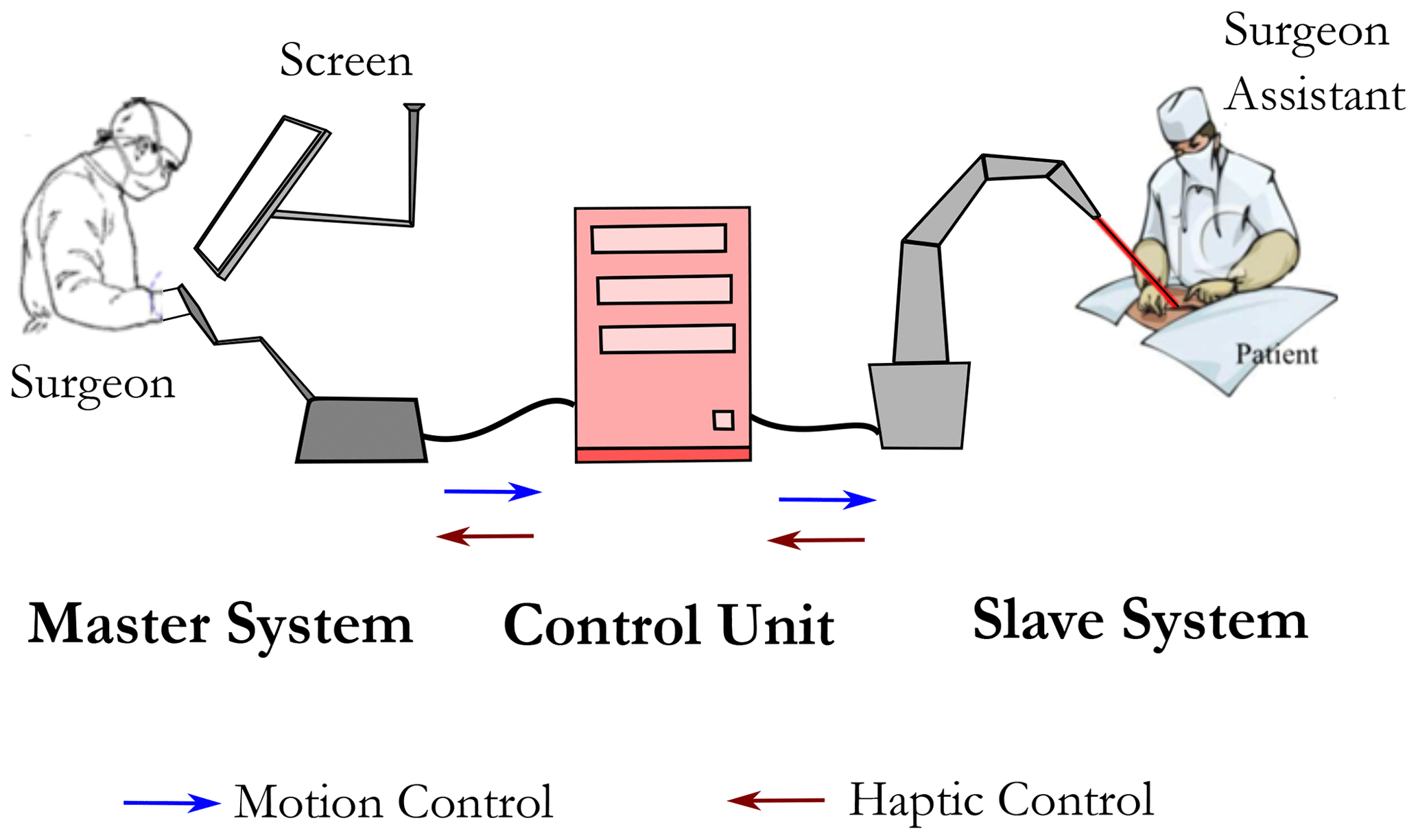
To improve minimally invasive surgery and cope with the previous drawbacks, the use of teleoperation robotic systems has emerged. The tools are held by slave robots and the surgeon manipulates these robots using master devices as presented in Fig. 2. This improvement makes the surgeon more comfortable and decreases movement limitations as well as the duration of the surgical operation.

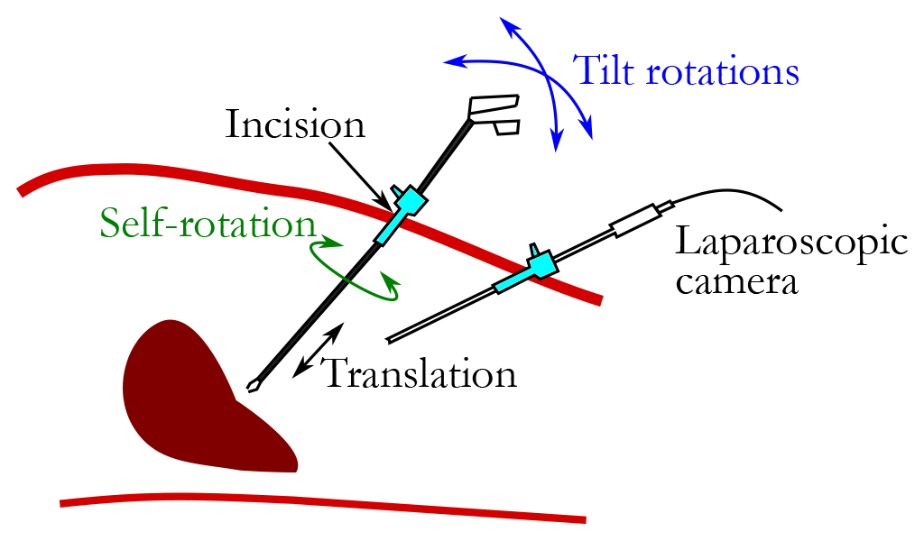
MIS limits the motion of tools inside the patient's body, as illustrated in Fig. 3. Only 4 DoFs are maintained and limited to rotations around the incision point and one translation within the tool axis. This limitation makes the design of master and slave robots for MIS teleoperation systems challenging. In fact, the development and control of teleoperation systems for MIS are still up to date (Boabang et al., 2020; Iijima et al., 2020; Saracino et al., 2020). Since there are always possible improvements, many studies focus on the identification of the required workspace for MIS (Thakre et al., 2008; Pisla et al., 2008; Cavusoglu et al., 2001). In fact, the workspace size depends on the surgical procedure (Konietschke et al., 2003). Here, we adopt the workspace identified in Laribi et al. (2012) through surgeon gesture records using a motion capture system. The workspace is described by a cone with a half-apex angle of 26∘. The translation range is around 112 mm. The self-rotation depends on the dexterity level of the surgeon as well as on the used technique. Nevertheless, it is considered here to be between ± 90∘. The kinematic of the master device must offer a workspace larger than the required one to guarantee the efficiency of the proposed device. As highlighted in the introduction, the expert surgeon who tested the first prototype of the haptic device reported the issue of the self-rotation limitation. This has been taken into account in the new design.
Peirs et al. (2004) measured the required force for MIS. The measurements were made in two directions: radial and axial. The radial force range is estimated at 1.7 N and the axial force at 2.5 N.
The next section deals with a new design of the hybrid-haptic device for robotized MIS.
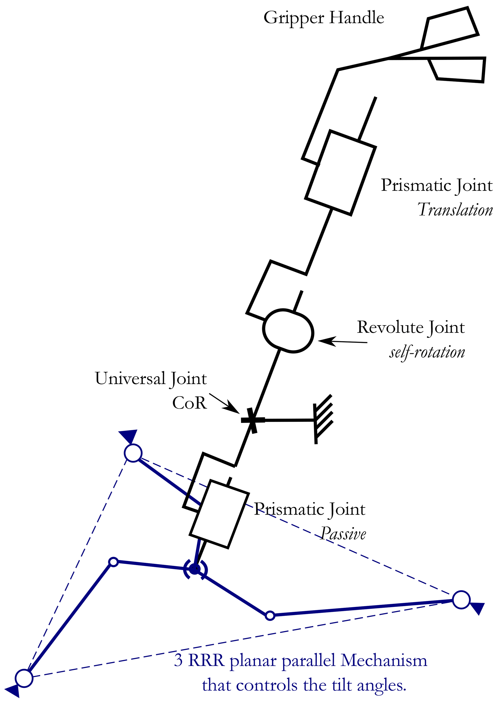
As introduced in the previous section, the MIS-required motions are rotations around a fixed point, called the CoR, and a translation. A new kinematics offering these movements is presented in Fig. 4. The proposed architecture is obtained by associating serial and parallel kinematics chains, where each one handles a part of the whole device DoF. The serial chain, composed of a prismatic joint and a revolute joint, allows us to handle the translation as well as the self-rotation. The parallel chain handles the two tilt motions. The required DoFs are generated in a disjointed way; therefore, the two chains are connected through a universal joint. This association helps to cope with the drawbacks of serial architecture. This latter is not suitable for developing haptic devices since the actuators are placed on joint axes. In this case, the required gravity compensation torques are increased and the dynamic behavior of the device is not negligible. Therefore, a parallel chain is linked to the serial chain through the universal joint to ensure the force control for the two tilt motions. Here, a 3-RRR planar parallel mechanism with 2 DoFs is selected as a parallel structure for the following reasons: reducing the required actuator torques, having a singular-free workspace, and having the most compact workspace after optimization (Saafi and Lamine, 2020). The self-rotation is decoupled from the parallel part because it requires a wide range of motion.
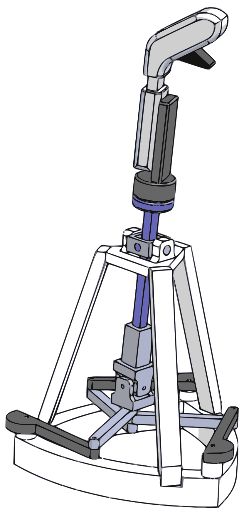
The computer-aided design (CAD) is presented in Fig. 5 to illustrate the appearance of the new architecture.
The haptic device measures the motion using sensors. Therefore, all joints of the serial part will be equipped with sensors (Fig. 6). This choice facilitates the resolution of the forward kinematic model of the master device. This model is required to measure the motion of the surgeon and then to control the surgical slave robot. The position of the end-effector can be expressed using the active angles of the new device as follows:
where λ is the distance between the end-effector and the CoR (located at point O). β1 and β2 are the rotation angles of the universal joint in the X and Y directions, respectively. β3 is the self-rotation angle.
The orientations of the tool axis, ZE, of the haptic device are expressed using ZYZ Euler angles (ψ, θ, and φ): ψ and θ for the tilt and φ for the self-rotation.
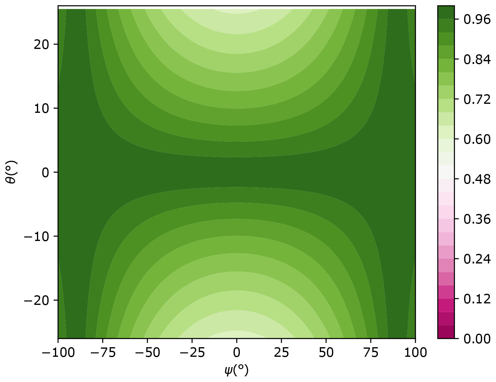
In order to illustrate the kinematic performance of the new proposed design, the dexterity index is measured using the inverse conditioning number of the orientation Jacobian matrix, Js, of the serial part of the HH device. Its expression is as follows:
The mechanism composed of the universal joint and the revolute joint can be considered a spherical wrist capable only of rotations around the center O. In this case, the Jacobian matrix Js relating the angular velocity of the moving platform and the active joint velocities is composed of the axes of the joints (Nouaille et al., 2010). The Jacobian matrix expression is as follows:
where Y1 is the second axis of the universal joint, as illustrated in Fig. 6.

Figure 7 shows the dexterity distribution of the new haptic device in the plane (ψ, θ). The new device presents good kinematic performances, since the dexterity is allowed to be higher than 0.6.
The serial part does not require optimization since all joints are decoupled. However, the haptic device must be compact. It must fit in a box with a height equal to 500 mm and width equal to 200 mm. Only the parallel part requires optimization. The next section deals with the optimization of the 3-RRR planar parallel manipulator.
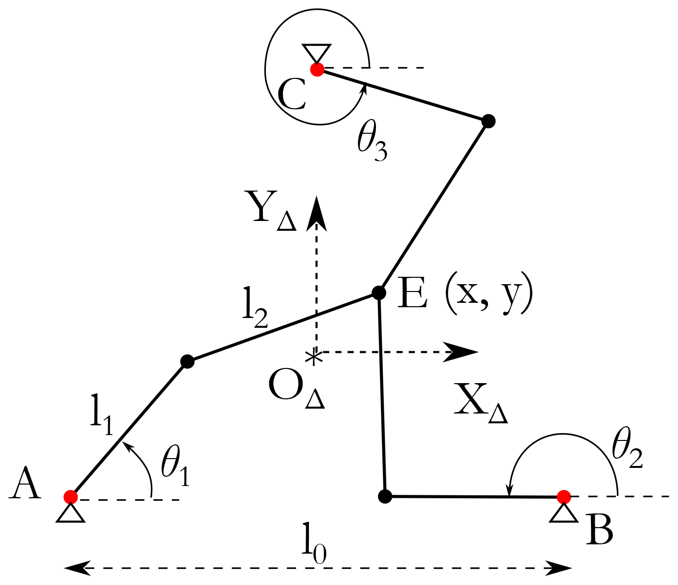
The redundant 3-RRR PPM is composed of three identical branches, as illustrated in Fig. 8. Each branch is composed of two links: one connected to the base and the other connected to the end-effector. The end-effector position is defined by point E and its (x, y) coordinates. The three active joints are placed on the vertices of an equilateral triangle such that l0 is the edge length. The base reference frame (OΔ, XΔYΔ) is placed at the center of the equilateral triangle. l1 and l2 are the sizes of the first link and the second link, respectively. θ1, θ2, and θ3 are the active joint angles.
This section focuses on the geometric optimization of the redundant PPM to fit the required MIS workspace.
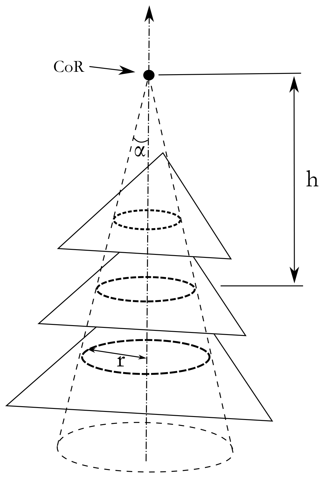
As shown in Fig. 9, the projection of the required workspace in the PPM plane is a circle. The radius of this circle depends on the distance, denoted h, between the center of rotation (center of the universal joint, Fig. 4) and the PPM plane. The angle α is considered equal to 26°. The two distances h and l0 are chosen manually to have a compact structure. The two geometric constants are equal to
The radius of the projected circle is equal to the following expression:
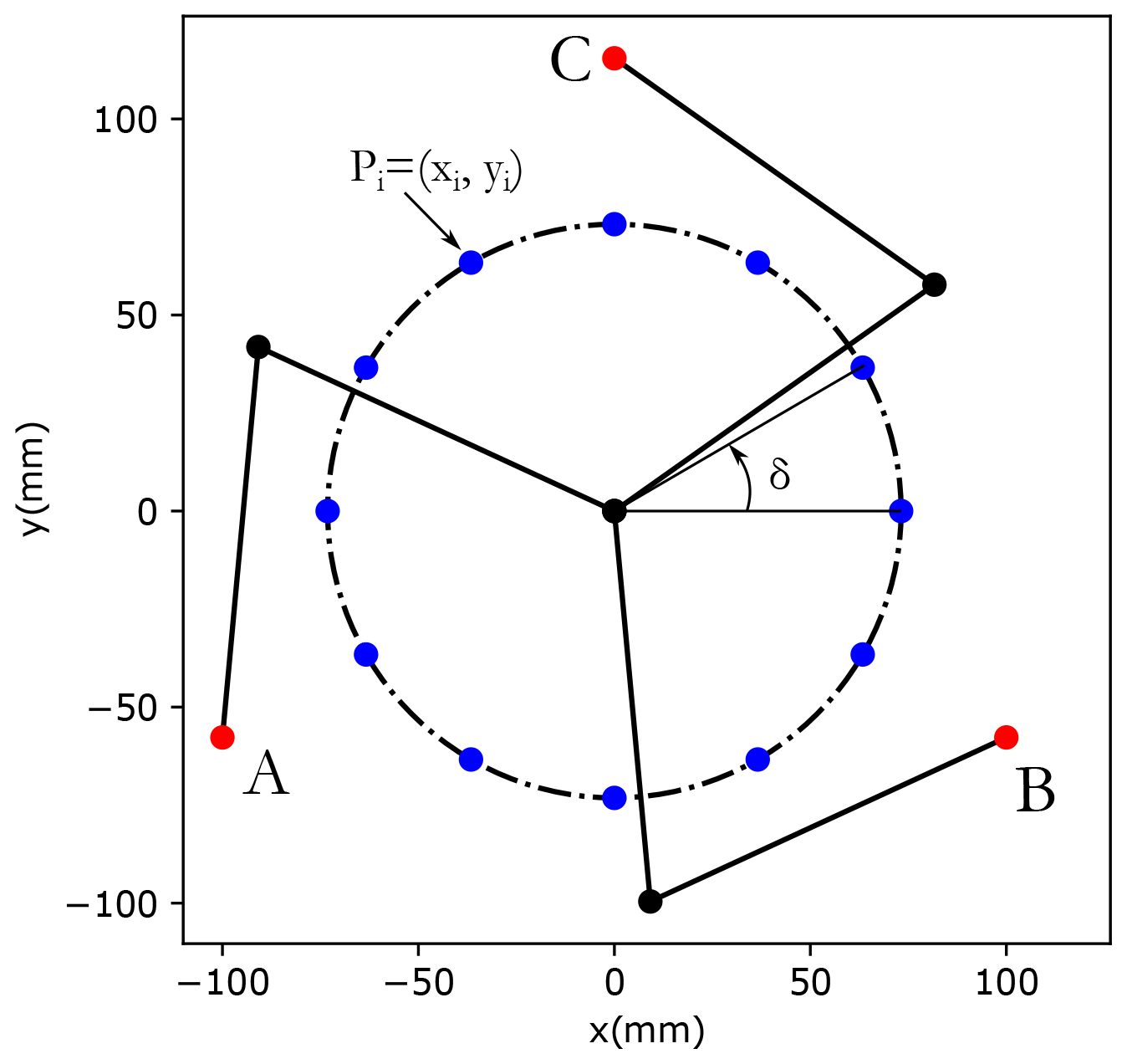
The border of the required workspace is shown in Fig. 10. The circle is discretized to 12 points defined as follows:
The optimization design vector is
where xL1 and xL2 are the length of the first link and the second link, respectively.
The optimization problem is formulated as follows:
The point Pi is within the workspace of the PPM if and only if the following condition is met:
where (xi, yi) are the coordinates of Pi () and (xj, yj) are the coordinates of the points (A, B, and C).
The proposed optimization approach is based on the minimization of an objective function f(xL) which is the quadratic sum of the robot links (xL1, xL2). The optimization is subject to one constraint which involves the workspace (WS) and aims to guarantee that the haptic device WS fits the prescribed one. A genetic algorithm is used to minimize the objective function, where the constraints are nonlinear and the lower and upper bounds of xLi are [50,200] in millimeters. Furthermore, the initial guess is in millimeters. As a result, the computed optimal design vector is
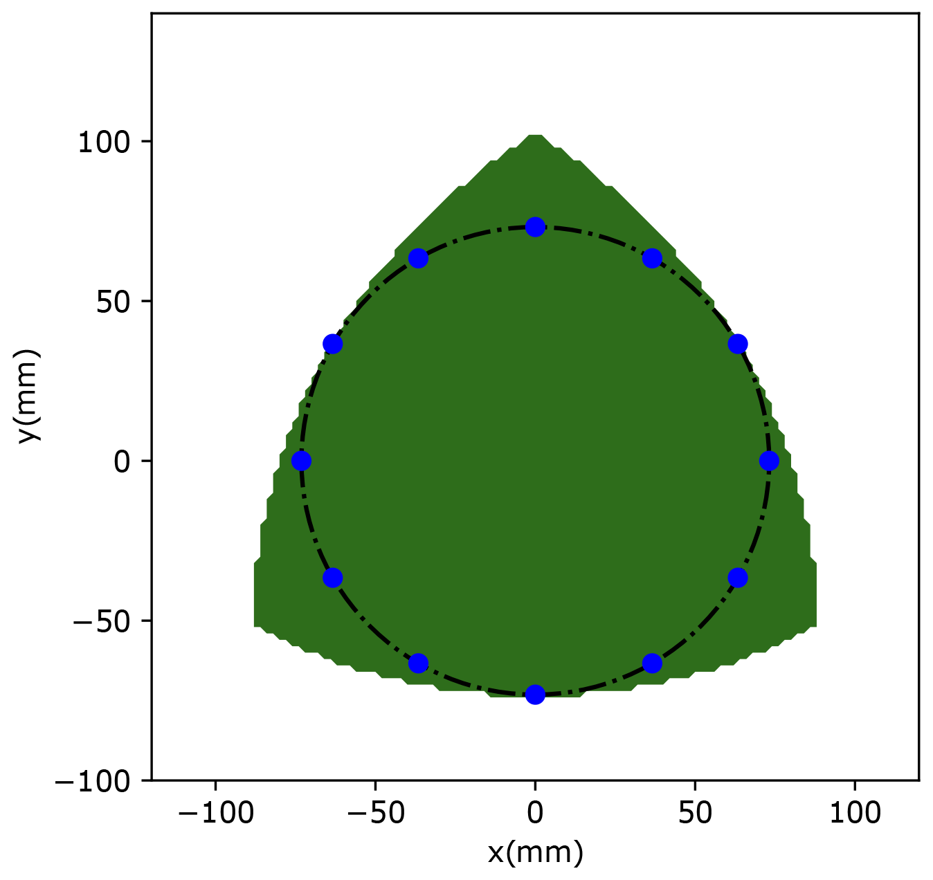
Figure 11 presents the workspace of the optimized PPM. Nevertheless, to move the serial singularity away from the border of the prescribed workspace, each component of x is increased by 5 mm. The following design vector was selected:
Figure 12 presents the workspace of the selected PPM with the prescribed area.
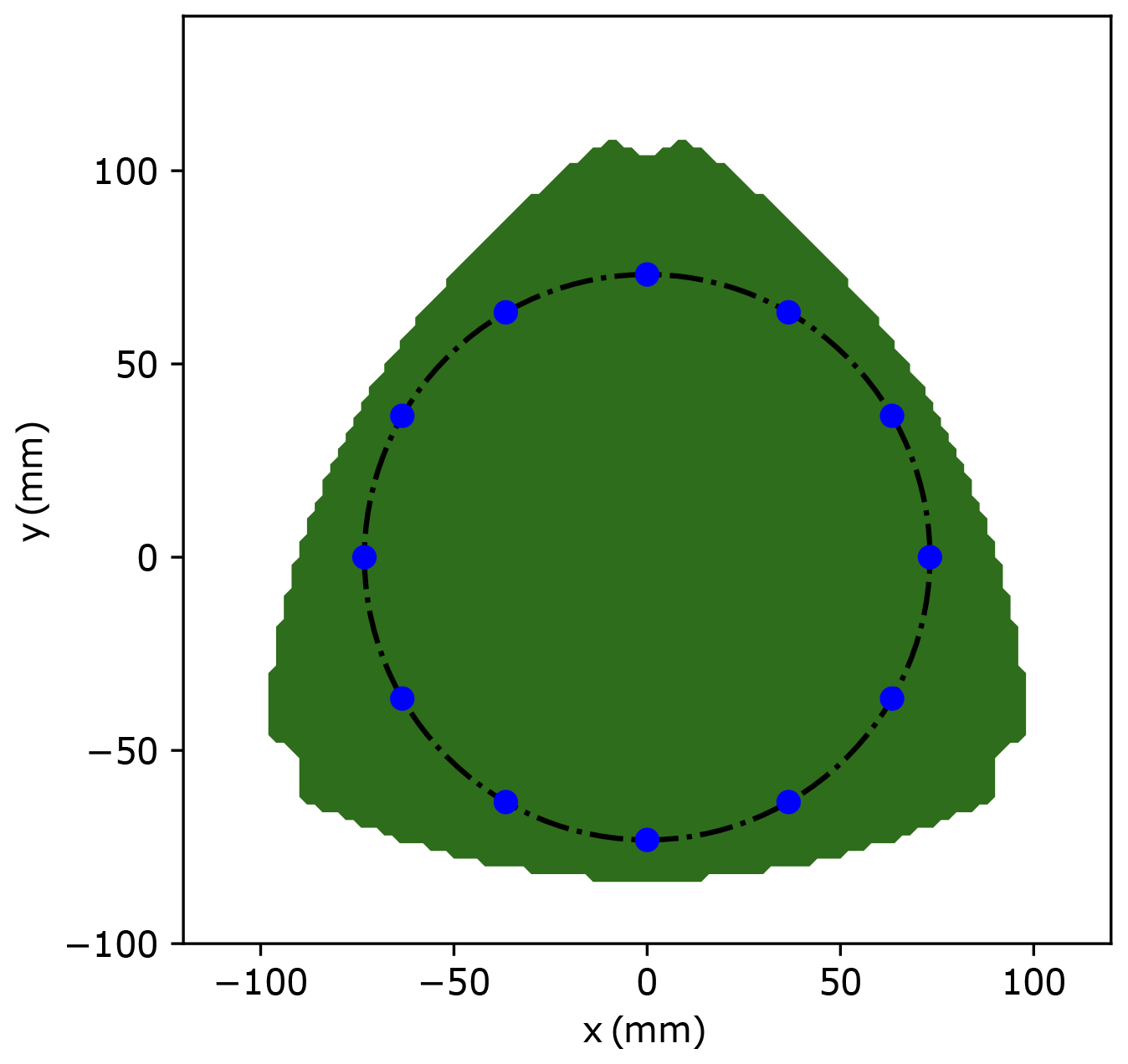
In this section, the geometrical parameters of the 3-RRR redundant PPM are optimized to obtain a compact structure. The next section focuses on the study of the haptic model.
Haptic devices apply forces and torques to the user's hand using actuators. As described before, for the proposed design, the self-rotation and the translation will each be equipped by a specific actuator. However, the universal joint will not be actuated. Instead, the optimized 3-RRR redundant PPM will be equipped with actuators. This section will focus on the development of the haptic model for the 3-RRR redundant PPM.
The kinematic model of the 3-RRR PPM is as follows:
where Jx is a 3×2 matrix called the parallel part of the Jacobian matrix, and Jθ is a 3×3 diagonal matrix called the serial part of the Jacobian matrix.
where
Expressions of variables Ai and Bi are given in Eq. (21).
Since Jθ is a diagonal matrix, the inverse of the Jacobian matrix can be easily expressed as follows:
For the non-redundant PPM, the relation between the force vector at the end-effector, F, and the actuated joint torques, τ, is as follows:
where J is the Jacobian matrix. The gravity effects are neglected because of the horizontal placement of the PPM.
For the redundant PPM, only the force vector can be expressed using the actuator joint torques as follows:
where G is the inverse of the Jacobian matrix.
The pseudo-inverse is used to express the torque vector τ using the force vector F as follows:
where (GT)+ is the pseudo-inverse of GT, I is the 3×3 unit matrix, and V is an arbitrary vector. is the null-space torque which can change the actuator torques τ without affecting the force vector F. To get the optimal torque distribution, the following optimization approach is employed:
As shown in the haptic model, the active angles (θ1, θ2, and θ3) are required to determine the Jacobian matrix. Since the 3-RRR PPM will not be equipped with sensors, the inverse kinematic model (IKM) will be used to determine the required angles. The next section studies the determination of the active angles using the sensors placed on the universal joint.
The IKM gives the active angles (θ1, θ2, θ3) as a function of the 3-RRR PPM end-effector position (x, y). The expression of the active angles is as follows:
where
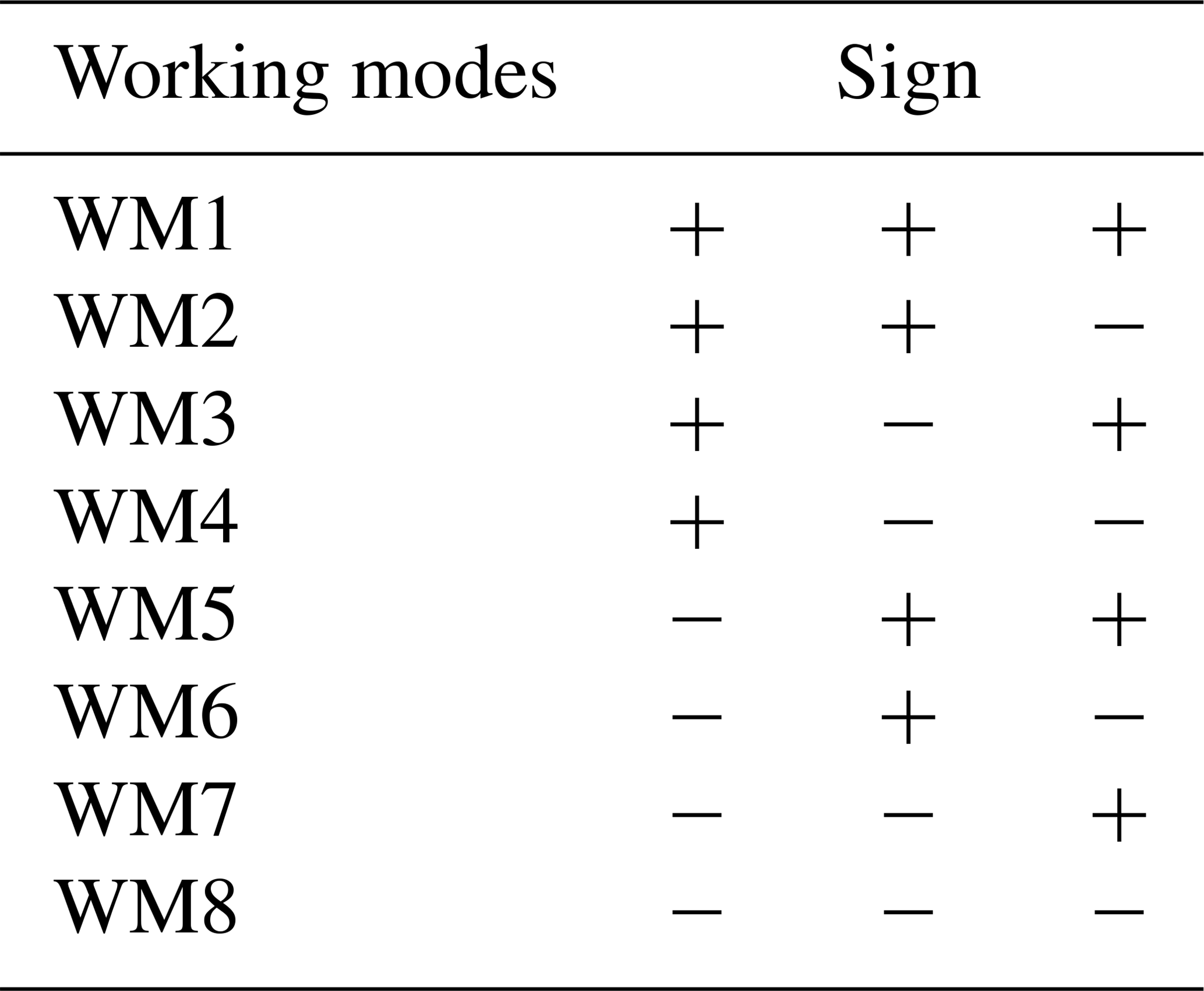
Each angle θi () has two possible solutions depending on the sign (±) in Eq. (20). The combination of all the solutions gives eight working modes (WMs) for the 3-RRR PPM enumerated in Table 1.
For the redundant PPM shown in Fig. 8, WM1 is considered with the sign (+) for the three angles' expressions.
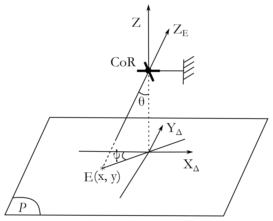
The IKM is not enough to determine the active angles since the position of the PPM end-effector is not known. Figure 13 shows the approach used to determine the position of the PPM end-effector, E, defined by the coordinates (x, y). The sensors measuring the tilt angles are placed on the universal joint at the center of rotation of the haptic device.
The PPM end-effector position can be expressed using ψ and θ as follows:
As detailed in the previous section, the gravity effect of the redundant 3-RRR PPM is neglected since it will be placed horizontally. However, the haptic device requires gravity compensation. The next section deals with the gravity compensation for the new haptic device.
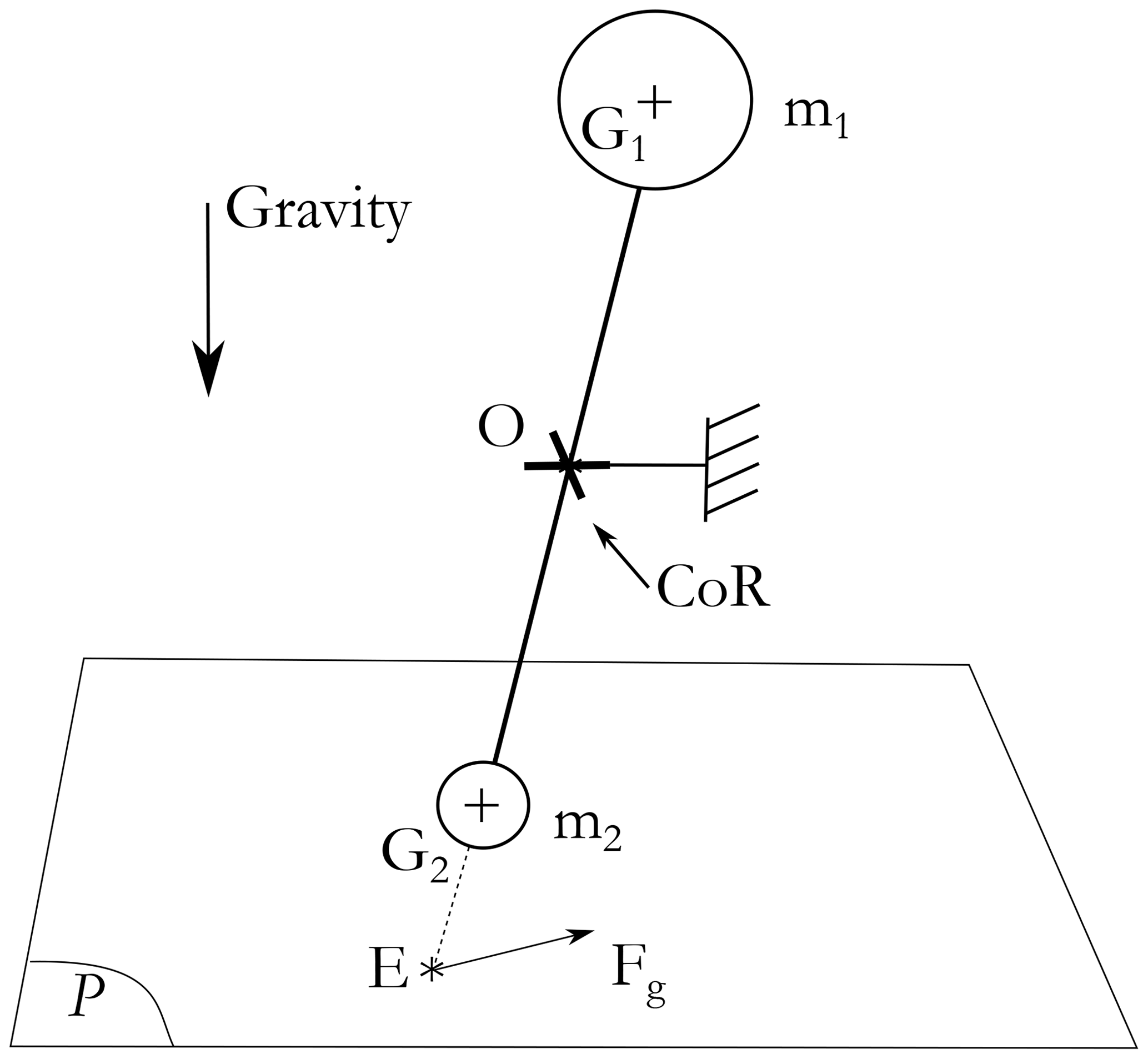
The hybrid-haptic device can be modeled as illustrated in Fig. 14. The upper part is defined by its center of gravity G1 and the mass m1 and the lower part by its center of gravity G2 and the mass m2. The upper part is composed of the gripper handle as well as prismatic and revolute joints, while the main component of the lower part is the passive prismatic joint. The upper part is expected to be heavier than the lower part that will compensate the gravity partially by the counterbalance effect.
The remaining part is compensated by the redundant 3-RRR PPM by generating the force Fg.
The gravity compensation problem can be formulated as follows:
where P1 and P2 are the gravity vectors of the upper and lower blocks, respectively.
To reduce the required force Fg to compensate the gravity, the two blocks must be balanced as much as possible. This issue will be handled when designing the prototype of the master device.
A numerical simulation of the gravity compensation model is carried out to calculate the required actuator torques. Table 2 presented the gravity compensation model parameters.
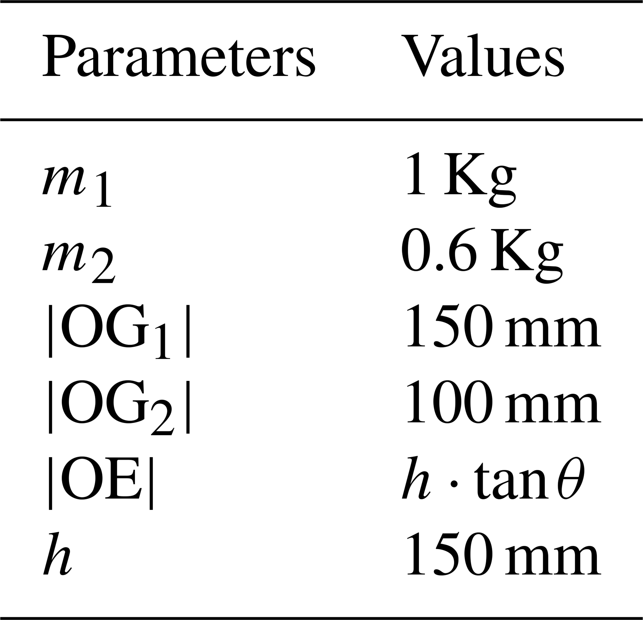
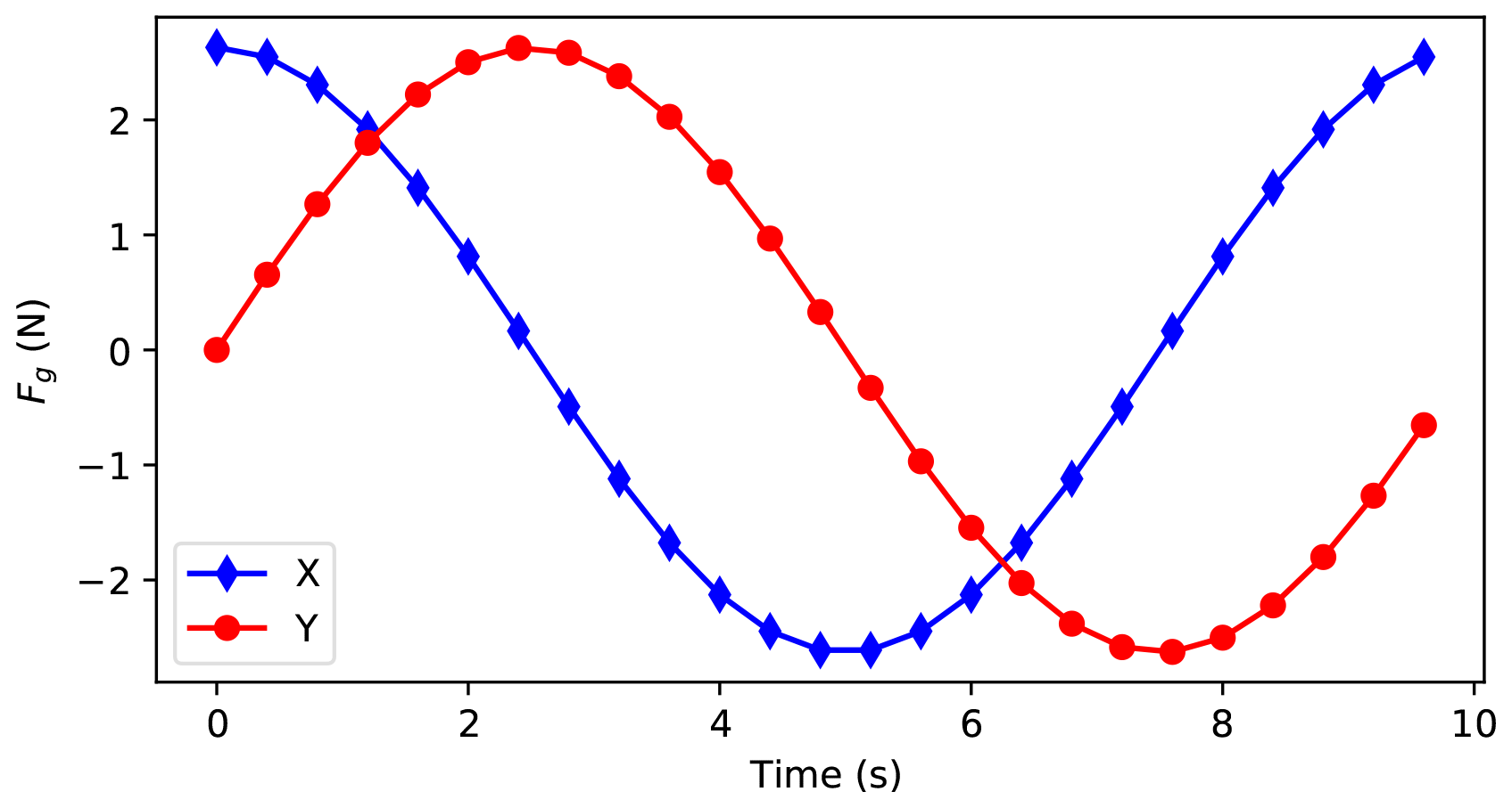
The compensation force Fg is given by the following expression:
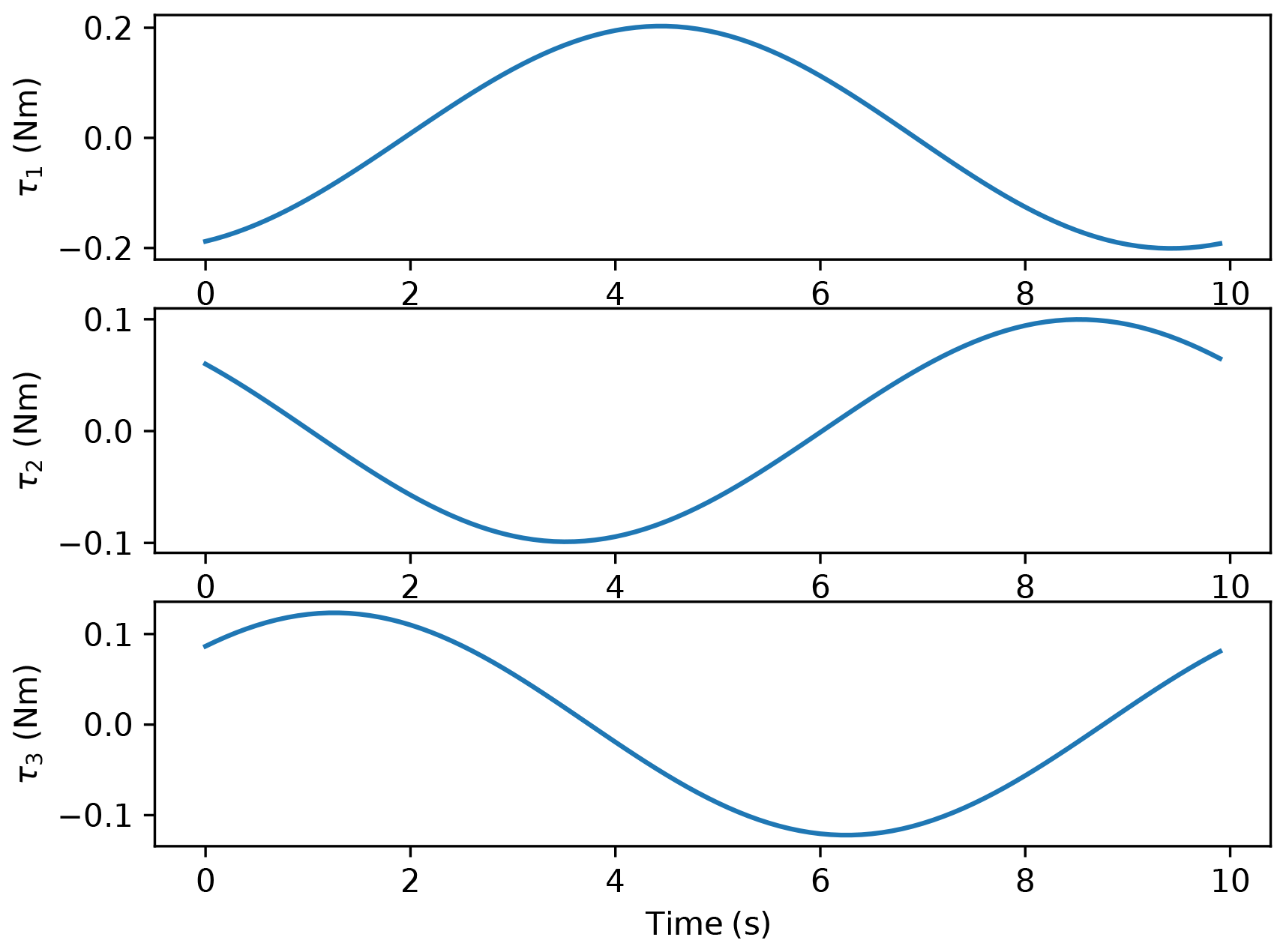
It is obvious that the compensation force is maximum when the tilt angle θ is maximum. Therefore, the simulation is made with θ equalling . The angle ψ is varied between 0∘ and 360∘. The compensation force Fg, calculated using Eq. (24), is shown in Fig. 15. The maximal gravity compensation force is equal to 2.6∘ N. The required actuator torques for gravity compensation are illustrated in Fig. 16. The maximum required actuated torque for compensating the gravity is equal to 0.2 Nm.
In the present work, a new hybrid spherical manipulator with 4 DoFs was presented and studied. The proposed manipulator, named the hybrid-haptic device (HH device), is intended to be used as a haptic device for laparoscopic surgery. The HH device is an association of two kinematic chains, serial and parallel. As the natural gesture of the surgeon, the HH device allowed them to handle disjointly the mobilities two by two, the two tilt motions and the translation and self-rotation. The serial chain is built out with installed sensors on its joints to compute the orientation and the position of the end-effector. However, the parallel chain, which is a redundant 3-RRR PPM with 2 DoFs, is used to ensure the force feedback and to compensate the gravity issue. The geometric parameters of the PPM are optimized to fit the prescribed workspace. The haptic and compensation models were discussed. The CAD prototype is presented and used to validate the proposed kinematic. Future works will focus on sensors and actuator selections, the development of a first prototype of the HH device, as well as the possible use of the same kinematics for the slave surgical robot.
All the data used in this paper can be obtained from the corresponding author upon request.
HS designed the new master device. HS and MAL co-wrote the paper. The research work was supervised by SZ.
The authors declare that they have no conflict of interest.
This paper was edited by Guowu Wei and reviewed by two anonymous referees.
Boabang, F., Glitho, R., Elbiaze, H., Belqami, F., and Alfandi, O.: A Framework for Predicting Haptic Feedback in Needle Insertion in 5G Remote Robotic Surgery, in: 2020 IEEE 17th Annual Consumer Communications & Networking Conference (CCNC), IEEE, 1–6, 2020. a
Cavusoglu, M. C., Villanueva, I., and Tendick, F.: Workspace analysis of robotic manipulators for a teleoperated suturing task, in: Proceedings 2001 IEEE/RSJ International Conference on Intelligent Robots and Systems, Expanding the Societal Role of Robotics in the the Next Millennium (Cat. No. 01CH37180), IEEE, 4, 2234–2239, 2001. a
Iijima, T., Matsunaga, T., Shimono, T., Ohnishi, K., Usuda, S., and Kawana, H.: Development of a Multi DOF Haptic Robot for Dentistry and Oral Surgery, in: 2020 IEEE/SICE International Symposium on System Integration (SII), IEEE, 52–57, 2020. a
Konietschke, R., Ortmaier, T., Weiss, H., Engelke, R., and Hirzinger, G.: Optimal Design of a Medical Robot for Minimally Invasive Surgery, 2, Jahrestagung der Deutschen Gesellschaft fuer Computer-und Roboterassistierte Chirurgie (CURAC), 1–8, 2003. a
Laribi, M. A., Riviere, T., Arsicault, M., and Zeghloul, S.: A design of slave surgical robot based on motion capture, in: 2012 IEEE international conference on robotics and biomimetics (ROBIO), IEEE, 600–605, 2012. a
Medellin-Castillo, H. I., Zaragoza-Siqueiros, J., Govea-Valladares, E. H., de la Garza-Camargo, H., Lim, T., and Ritchie, J. M.: Haptic-enabled virtual training in orthognathic surgery, Virtual Reality, 87, 1–15, 2020. a
Nisar, S., Endo, T., and Matsuno, F.: Design and kinematic optimization of a two degrees-of-freedom planar remote center of motion mechanism for minimally invasive surgery manipulators, J. Mech. Robot., 9, 1–9, 2017. a
Nouaille, L., Smith-Guérin, N., Poisson, G., and Arbeille, P.: Optimization of a 4 dof tele-echography robot, in: 2010 IEEE/RSJ International Conference on Intelligent Robots and Systems, IEEE, 3501–3506, 2010. a
Peirs, J., Clijnen, J., Reynaerts, D., Van Brussel, H., Herijgers, P., Corteville, B., and Boone, S.: A micro optical force sensor for force feedback during minimally invasive robotic surgery, Sensors Actuators A-Phys., 115, 447–455, 2004. a
Pisla, D., Plitea, N., and Vaida, C.: Kinematic modeling and workspace generation for a new parallel robot used in minimally invasive surgery, in: Advances in robot kinematics: analysis and design, Springer,459–468, 2008. a
Preault, C., Saafi, H., Laribi, M. A., and Zeghloul, S.: 4haptic: A Dexterous 4 do fs Haptic Device Based on Delta Architecture, in: Computational Kinematics, Springer, 307–314, 2018. a, b
Saafi, H. and Lamine, H.: Comparative Kinematic Analysis and Design Optimization of Redundant and Nonredundant Planar Parallel Manipulators Intended for Haptic Use, Robotica, 38, 1463–1477, 2020. a
Saafi, H., Laribi, M. A., and Zeghloul, S.: Redundantly actuated 3-RRR spherical parallel manipulator used as a haptic device: improving dexterity and eliminating singularity, Robotica, 33, 1113–1130, 2015. a
Saafi, H., Laribi, M. A., Zeghloul, S., and Ibrahim, M. Y.: On the development of a portable, cost effective and compact master/slave system for robot-assistec Minimally Invasive Surgery, in: 2017 IEEE International Conference on Mechatronics (ICM), IEEE, 290–296, 2017. a, b
Saafi, H., Laribi, M. A., Zeghloul, S., and Arsicault, M.: On the development of a new master device used for medical tasks, J. Mech. Robot., 10, 1–6, 2018. a, b
Saafi, H., Laribi, M. A., and Zeghloul, S.: Forward Kinematic Model Resolution of a Special Spherical Parallel Manipulator: Comparison and Real-Time Validation, Robotics, 9, 1–16, 2020. a
Saracino, A., Vrielink, T. O., Menciassi, A., Sinibaldi, E., and Mylonas, G.: Haptic intracorporeal palpation using a cable-driven parallel robot: a user study, IEEE Transactions on Biomedical Engineering, IEEE, 67, 3452–3463, 2020. a
Tavakoli, M., Patel, R. V., and Moallem, M.: A haptic interface for computer-integrated endoscopic surgery and training, Virtual Reality, 9, 160–176, 2006. a
Thakre, A., Bailly, Y., Sun, L., Van Meer, F., and Yeung, C.: Is smaller workspace a limitation for robot performance in laparoscopy?, J. Urology, 179, 1138–1143, 2008. a
Tobergte, A., Helmer, P., Hagn, U., Rouiller, P., Thielmann, S., Grange, S., Albu-Schaffer, A., Conti, F., and Hirzinger, G.: The sigma. 7 haptic interface for MiroSurge: A new bi-manual surgical console, in: Intelligent Robots and Systems (IROS), 2011 IEEE/RSJ International Conference on, IEEE, 3023–3030, 2011. a
van den Bedem, L., Hendrix, R., Rosielle, N., Steinbuch, M., and Nijmeijer, H.: Design of a minimally invasive surgical teleoperated master-slave system with haptic feedback, in: Mechatronics and Automation, 2009, ICMA 2009, International Conference on, IEEE, 60–65, 2009. a, b
- Abstract
- Introduction
- Minimally invasive surgery
- New hybrid spherical kinematics for the master device
- Optimization of the 3-RRR redundant planar parallel manipulator
- Haptic model
- Determination of the 3-RRR PPM active angles
- Gravity compensation
- Conclusions
- Data availability
- Author contributions
- Competing interests
- Review statement
- References