the Creative Commons Attribution 4.0 License.
the Creative Commons Attribution 4.0 License.
 | 20 Dec 2021
Precise mathematical model for the ratchet tooth root bending stress
Chao Liu
Ning Ding
Jingsong Duan
Lili Zhou
Shanfu Cui
Shuna Jiang
Aofei Li
A ratchet is an essential component of the ratchet pawl mechanism. But the traditional ratchet strength check method has certain limitations in the design process. In this paper, the stress analysis of the ratchet is discussed and a precision mathematical model for the ratchet tooth root bending stress is proposed for the first time. This model was established by the folded section and defined by the incision effect theory. To test the prediction ability of the proposed mathematical model, the maximum stress of three standard ratchets and one non-standard ratchet were analyzed by the FEA (finite element analysis) method. The non-standard ratchet was adapted in the ratchet experiment to analyze its maximum stress. The analysis results presented in this paper show that the proposed mathematical model has a good predictability, regardless of whether it is a standard or non-standard ratchet. It is recommended that this model can be used to predict the ratchet tooth root bending stress in the ratchet design process.
- Article
(5312 KB) - Full-text XML
- BibTeX
- EndNote


A ratchet is an essential component of the ratchet pawl mechanism, which has the advantages of a simple structure, convenient manufacture, and the time ratio of moving or stopping can be controlled by the selecting drive mechanism. It is widely used in machine tools, safety nets, for lifting permanent magnets and other structures that require a unidirectional intermittent motion or anti-reverse function. However, there are few references or design methods in the literature dealing specifically with the analysis of ratchet bending stress. Given its extended applications, the stress research of the ratchet has great significance from the perspective of theoretical and engineering applications.
It should be noted that the traditional ratchet strength check method is based on the module published elsewhere (Daxian, 2008; Bangchun, 2010; Datong and Lingyun, 2011). That is, the designed module needs to be larger than the checked one. This method for checking can ensure the security for the condition that the position of the ratchet and pawl is fixed. The contact between both is mostly line contact. But when the pawl is driven and moved with other components, this method will no longer work, and this method for checking cannot reflect the ratchet stress. Take the example of lifting a permanent magnet (Ning et al., 2011, 2019a, b); its pawl is a drive, mounted on the rotating arm, and is rotated. In this condition, the contact type between the ratchet and pawl is a surface contact. Its stress state is much better than that of line contact.
So far, there are few studies on the ratchet tooth root bending stress (Da and Chongxian, 1998; Mingjun et al., 2015; Yukun et al., 2017). In view of the similarity between the ratchet and the gear, the bending stress studies of the gear have a certain reference for the ratchet stress studies (Hongbin et al., 1999; Litvin-Faydor et al., 2005; Gonzalez-Perez et al., 2011; Zhongming et al., 2016; Cheng et al., 2017; Fajia et al., 2017; Lisle-Timothy et al., 2017; Gonzalez-Perez and Fuentes-Aznar, 2018; Yonghu et al., 2018; Min et al., 2019; Nan et al., 2019).
In the mechanics of materials, almost the whole stress calculation is based on the flat section hypothesis. The bending, stretching, compressing and torsion of beams are resolved on the basis of this hypothesis, and the gear is no exception. The gear tooth is generally assumed to be a cantilever beam when calculating the gear tooth root bending stress. However, the stress based on the flat section is imprecise due to the tooth profile being involute. Thus, the stress correction factor is introduced to correct the results. This method is widely used in practical engineering applications for its simplicity. With regard to the ratchet, its tooth can be considered as being a variable section beam. The ratchet tooth root bending stress can also be calculated by the flat section hypothesis. But figuring out the stress correction factor requires thousands of experiments. This is a lengthy and complex process.
Besides the flat section hypothesis, there is also the folded section hypothesis and the circular section hypothesis. These hypotheses are collectively known as the non-flat section hypotheses and were proposed by the scientist A. B. Verkhvsky, of the former Soviet Union, in 1967. Due to the non-flat section hypothesis being very close to the actual fractured shape of the teeth, its calculation is sufficiently precise, and the stress correction factor is no longer needed.
The objective of this study is to introduce a precise mathematical model for the ratchet tooth root bending stress. This model can acquire the actual value of the ratchet tooth bending stress and define the basic rules for the ratchet strength check.
2.1 Incision effect theory
Before analyzing the ratchet tooth root bending stress, it is necessary to introduce the incision effects theory (Verkhvsky et al., 1967). Take the example of a steel plate with an incision, which is shown in Fig. 1.
First, we assume that the incision is fairly shallow. Thus, the depth of the incision crack under a collapsing force will not affect the entire width of the steel plate, as in the following:
where ρ is the curvature of the incision. t is the depth of the incision. a is the width of the steel plate.

For this kind of plate, the effects of a shallow incision would be limited to a certain depth, as follows:
where a0 is the maximum depth of the incision crack under a collapsing force.
2.2 Analysis of the ratchet tooth root bending stress
According to the analysis of the gear, the maximum stress should be generated at the tooth root fillet when the ratchet is being loaded. To ensure that the designed ratchet meets the strength requirement, the folded section hypothesis is introduced to analyze this maximum stress.
In the folded section hypothesis, the equivalent critical cross section includes two parts, where the first one can be determined by the theory of the incision depth effects. For most ratchets, it satisfies the requirement that is , so the length of the first one is as follows:
where tr is the distance between the addendum circle and dedendum circle of the ratchet.
Along the length lAB, we make the first polyline. Then, we draw a radial from the tooth root fillet center and go through point A, which is the mid-point of this arc. We take point A as the center and the length lAB as the radius to draw another arc; this arc intersects the radial at a point which is named point B. The position of points A and B is shown in Fig. 2.
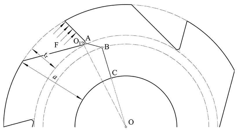
The second part of the equivalent critical cross section is determined by its geometric structure. We connect points B and O so that the line BO intersects the axle hole at point C. The polyline ABC is the projection of the equivalent critical cross section on the front (it is also named the component hazard section).
As can be seen from Fig. 2, ratchet teeth are asymmetrical structures. If the ratchet is cut along the radial direction and the circular contour is straightened, then a steel plate with asymmetrical incision is shown. For the asymmetrical structure, its neutral layer can be determined by the area of the stress diagram as follows (Verkhvsky et al., 1967)
where a0 is the projection of lAB in the radial direction, ya is the distance between the dedendum circle and neutral layer, and yb is the distance between the neutral layer and the axle hole.
According to the neutral plane, when the ratchet is applied at force F, the torque M is as follows:
where L is the length of the arm of the force.

For the bending deformation, tension and compression occur simultaneously. The ratchet is no exception. When the ratchet tooth is loaded, the polyline AB and BD will be tense. To analyze its deformation, we draw another polyline A1B1C1 in the same way as the polyline ABC, but below it, take a microelement KF between AB and A1B1 and take another microelement K1F1 between BD and B1D1. When the ratchet tooth deforms, the line BD is pivoted by an angle Δγ around the point D to B2D and the line AB around to A2B2. This is shown in Fig. 3. The microelement KN is stretched to KF, and K1N1 is stretched to K1F1. Now assume that there is no lateral pressure between microelement. According the Hook's law, the stress of microelement KN and K1N1 is as follows:
In Eq. (6), KN is as follows:
where ε1 and ε2 are the relative elongation of the microelement, E is the elasticity modulus, u1 is the distance between the point B and the microelement KF, and α is the angle of the line AB and the line O1O.
The compression occurs in the BD of the second polyline BC. It is also pivoted by an angle Δγ around the point D to DC2. Now take a microelement K2N2 between the line DC and the line D1C1. When DC is pivoted, then the microelement K2N2 is compressed into K2F2. Then, assume that there is no lateral pressure between microelement. According the Hook's law, the stress of microelement K2N2 is as follows:
where u3 is the distance between the point D and the microelement K2F2.
In the following, according to the moment equilibrium condition:
where b is the width of the ratchet.
Substitute Eqs. (6), (7) and (9) into Eq. (10) and take the terms that do not change with u1 and u2 and u3 outside the integral symbol as follows:
For convenience, let the integral in the square bracket equal N and solve it as follows:
Here, N is the section factor which represents the geometric properties of the ratchet.
Substitute Eqs. (11) and (12) into Eqs. (6), (7) and (9). The stress at any point on the polyline ABC can be obtained by the following equation:
To obtain the maximum stress of the critical cross section of the equivalent at the point A, let u1=lAB.
where σ1 is the maximum ratchet tooth root bending stress. Compare σ1 with the bending fatigue limit stress σFlim. If , then the design ratchet meets the strength requirement.
To verify the above theory, the FEA (finite element analysis) method was utilized to analyze the ratchet tooth root bending stress. In this analysis, three standard and one non-standard ratchets were adapted (the non-standard ratchet was designed to fit the hollow shaft. When limited by the structure, it has a smaller contact area than the standard one and a larger shaft hole). Their structure data are listed in Table 1. The analysis 3D models are shown in Fig. 4. To save analysis time, these models ignore the keyway and some chamfering features which will not affect the analysis results.
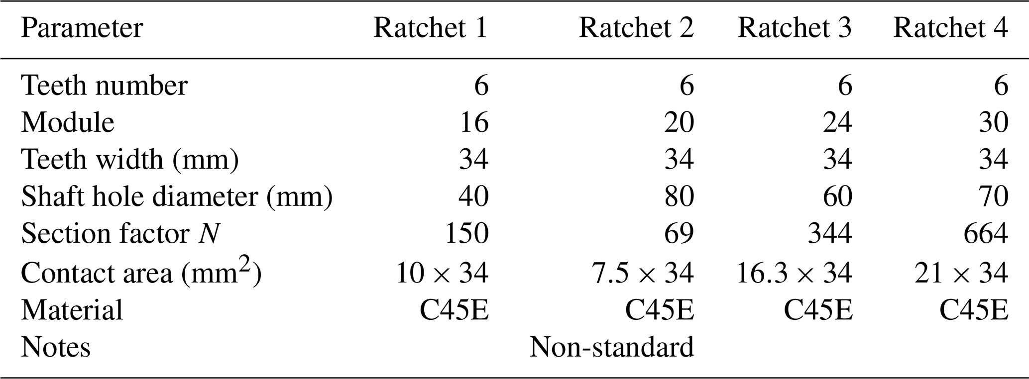
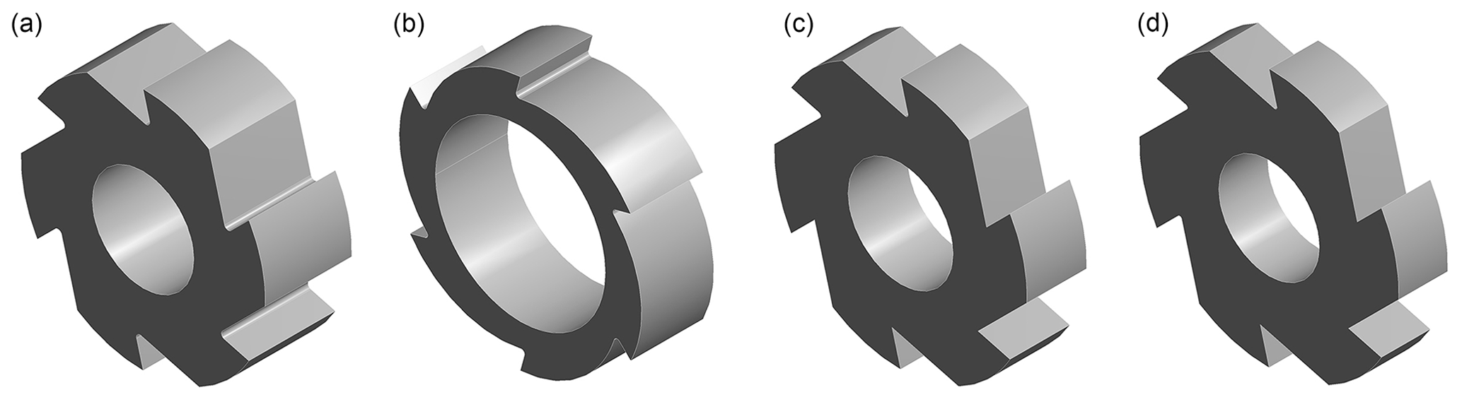
Figure 4A ratchet 3D model, showing (a) ratchet 1, (b) ratchet 2, (c) ratchet 3 and (d) ratchet 4.
In the mesh process, the meshing method is swept, which will give the preference to the hexahedral element, and the mesh destiny of the tooth root fillet was refined to reduce the effect of the stress concentrate. The mesh result of ratchet 2 is shown in Fig. 5.
After the mesh operation, the material C45E was sent to the model. Its main parameters are shown in Table 2.
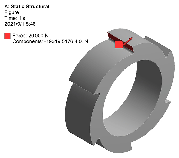
According to the actual work demand, the fixed support was added to the shaft hole of ratchet, and the concentrated force was applied to the working surface of the ratchet, as shown in Fig. 6.
In the solution information, the equivalent stress and the equivalent strain were added and run to resolve the above setting finish. The analysis results will be shown in the form of colored stress patterns. For the example of ratchet 2, its colored stress pattern under 20 000 N is shown in Fig. 7.
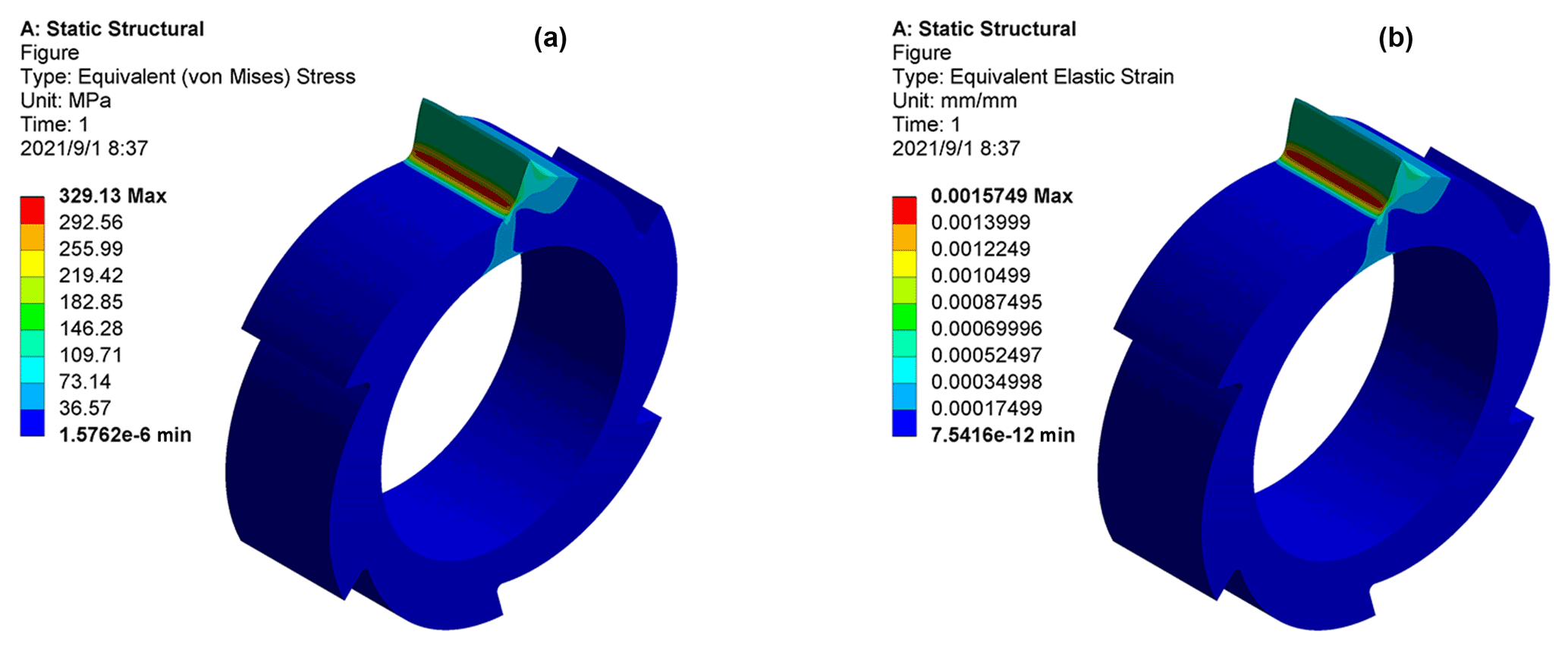
Figure 7Analysis results under 20 000 N, with the (a) ratchet stress distribution under 20 000 N and the (b) ratchet strain distribution under 20 000 N.
As can be seen from Fig. 7, the maximum stress generated at the root fillet of the ratchet, when the loading force reaches 20 000 N, is 329.13 MPa. The mathematical model's stress value is 356.09 MPa. Its deviation is about 7.57 %.
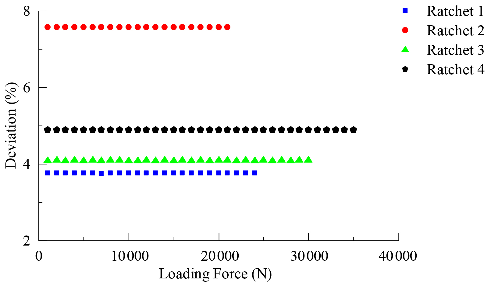
Analysis results of other ratchets are shown in Fig. 8 in the form of a line chart. The results of the mathematical model are also shown in the chart to make a contrast. Its deviations are shown in Fig. 9.
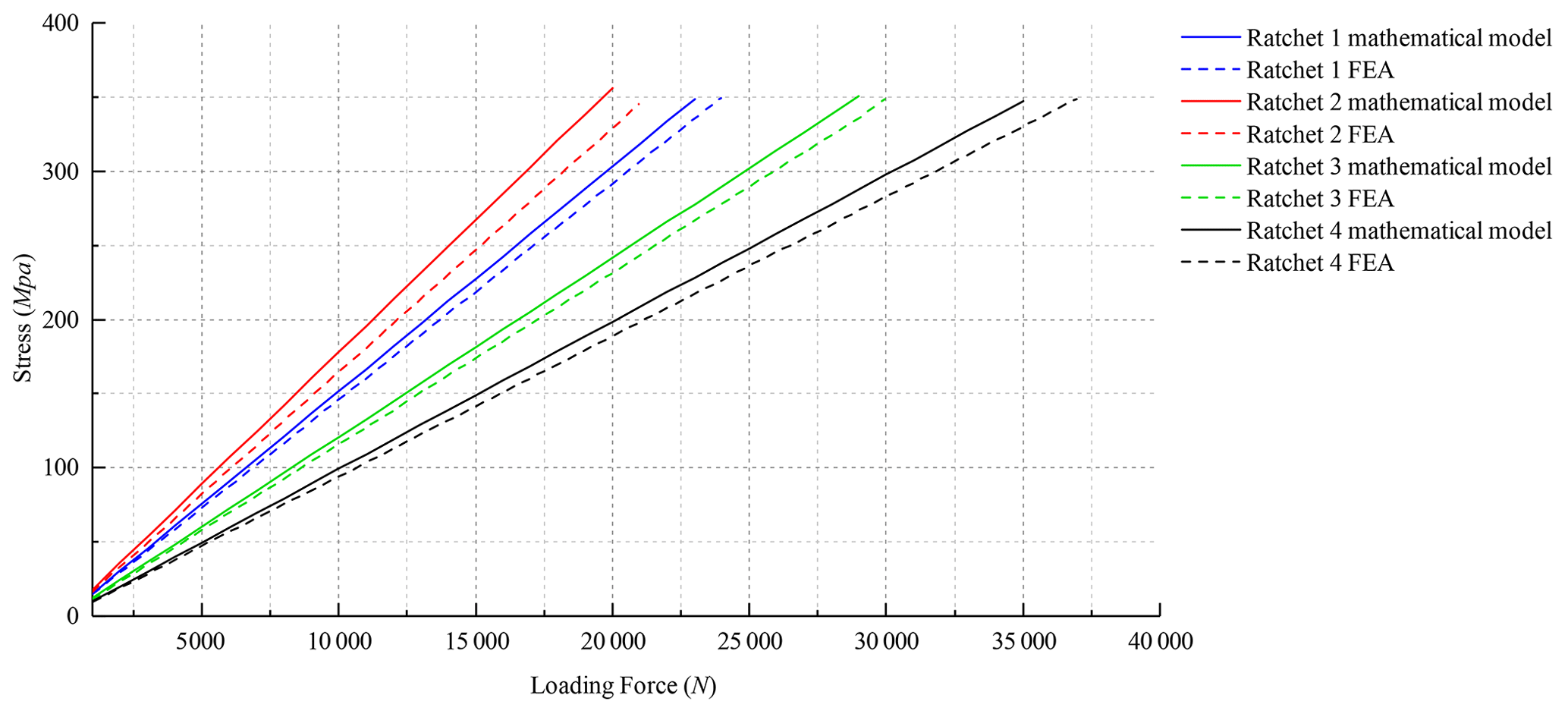
As can be seen from Figs. 8 and 9, the simulation data fit well with the model analysis data, and the model analysis data are slightly larger, which can ensure the design safety to a certain extent.
It also should be noted that the non-standard ratchet has a larger deviation compared to the other standard ratchets. The deviation of ratchet 1 is about 3.75 %, the deviation of ratchet 2 is about 7.57 %, the deviation of ratchet 3 is about 4.08 %, and the deviation of ratchet 4 is about 4.88 %.
The reason for this is that the non-standard ratchet, which has a big shaft hole, has a better torsion resistance. A big shaft hole increases the distance between the ratchet center and the material of shaft hole, which will increase its torsion resistance. When the ratchet was loaded with a constant force, the torsion borne by the material of the tooth root is big, and its torsion resistance is big. Conversely, the torsion borne by the material of the center is small, and its torsion resistance is small. So, the mean torsion resistance is small. But if the material outer is moved, the torsion resistance of the shaft hole material will increase, and the mean torsion resistance will also increase. This leads to a larger deviation with the standard ratchets.
For the standard ratchet, its size variation has a certain regularity. For example, the ratchet tooth height increases by 1.5 for every increase of 2 modules (Bangchun, 2010). That means that its stress variation also has a corresponding regularity. But for the non-standard ratchet, it does not have this regularity because its size is often determined by the working conditions. This will make its stress variation have a different trend compared with the standard ratchet, and this has been proved by the FEA method. If the proposed mathematical model can make a good prediction for the non-standard ratchet, then it can also do the same thing for the standard ratchet.
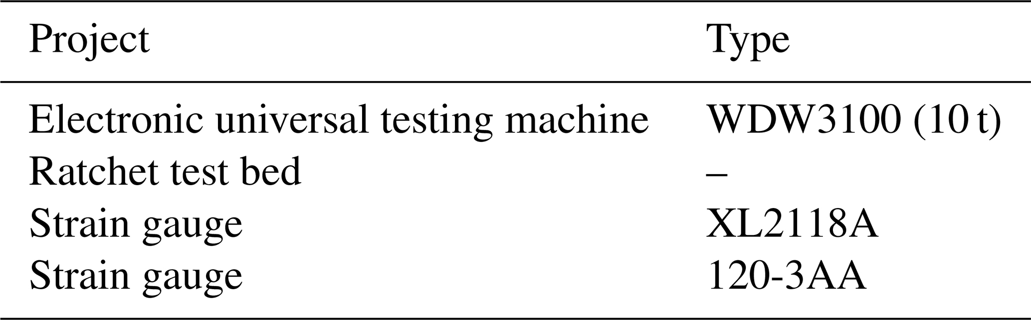
According the above analysis, the non-standard ratchet was adapted as the experimental ratchet. Its parameters are shown in Table 1. The experimental ratchet is shown in Fig. 10. The type of apparatus and devices for ratchet experiment are shown in Table 3.

4.1 Experiment apparatus and its principle
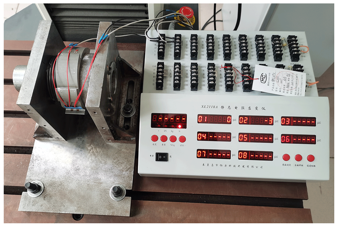
To acquire the maximum stress, the strain gauges were pasted on the tooth root fillet, which is shown in Fig. 11.
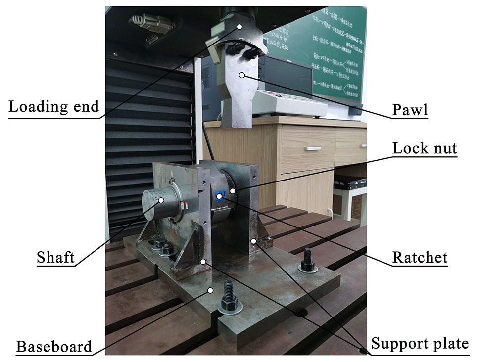
The structure of the ratchet test bed is shown in Fig. 12. It consists of a baseboard, shaft, pawl, lock nut, ratchet and support plate. The baseboard was bolted on the working table of an electronic universal testing machine. The pawl was fixed on the loading end of electronic universal testing machine. The shaft support is the L-shaped plate, which was bolted to the test bed bottom. The shaft and the ratchet were connected by the buttress thread, which only transmits power in one direction. The lock nut was soldered to the shaft to prevent the rotation of the ratchet under load.
The experiment was carried out as follows: we operated the electronic universal testing machine to lower the pawl to the level of the working surface of the ratchet. Then, we loosened the shaft support bolts and pushed the test bed to the position where the pawl coincides with the ratchet-tooth-loaded surface. Thereafter, we adjusted the ratchet and loading pawl until full contact was realized.
Then, we applied force to the working surface of ratchet and recorded the readings on strain gauge when the force reached the set value.
4.2 Experiment results and discussion
In the experiment process, each ratchet tooth was pasted into two sets of strain. We averaged the two sets of data and multiplied the elastic modulus E to obtain its stress. The jaw vise was used to assemble and disassemble the ratchet, and two teeth were deformed in this process. So, only four teeth could be tested. Finally, the stress data of three teeth were collected successfully. These experimental data are shown in Fig. 13, and the mathematical model results are also shown in the figures to make a contrast. Its deviations under different forces are shown in the right-hand side of Fig. 13.
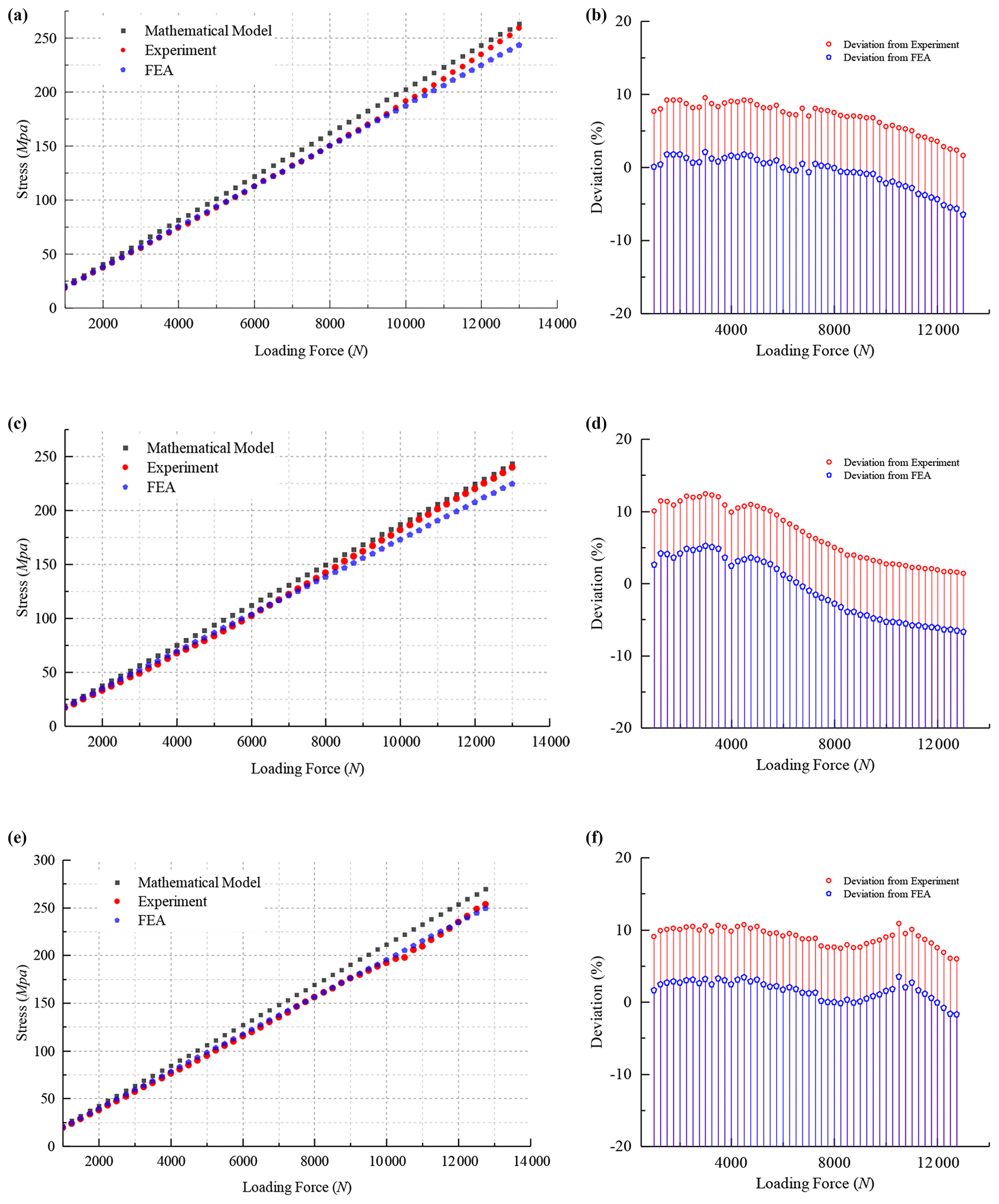
Figure 13The experimental data of ratchet 2. The comparison between the experiment and mathematical model and its deviation for (a, b) tooth 1, (c, d) tooth 2 and (e, f) tooth 3.
As can be seen from Fig. 13, the experimental data fit well with the model analysis data and are also larger. The average deviation between the mathematical model and the experiment of tooth 1 is approximately 6.9 %, tooth 2 is approximately 6.8 %, and tooth 3 is approximately 9 %.
It also should be noted that the average deviation between the mathematical model and experiment is more than 6 %, and the experimental data are closer to the simulation data. This further verifies that the non-standard ratchet, which has a big shaft hole, has a better torsion resistance.
Apart from that, the deviation between the experimental data and the simulation data and the model analysis data is not constant and shows a decreasing trend with the loading force. The reason for that has two aspects. First, the low machining precision of the ratchet test bed causes a tiny gap between the lock nut and the ratchet, and it could not be eliminated completely by preloading. So, the ratchet will rotate on a tiny angle, with the loading force and results in a variable deviation.
Second, the ratchet tooth will have a tiny deformation as the loading force increases in the loading process. This deformation changes the contact condition and results in a variable deviation.
This study offers a precision mathematical model for the ratchet tooth root bending stress, which was established by the folded section. The FEA was utilized to analyze the maximum stress of three standard ratchets and one non-standard ratchet. The analysis results show that the mathematical model prediction values are consistent with the FEA. The deviation of standard ratchet does not exceed 5 %, and the deviation of non-standard ratchet does not exceed 8 %.
Afterwards, the ratchet experiment was designed to analyze the actual stress of the non-standard ratchet. The experiment results show that the mathematical model also has a good prediction for the non-standard ratchet. The average deviation does not exceed 9 %.
By analyzing the FEA method and the ratchet experiment, the proposed mathematical model has a good predictive ability for the standard ratchet and the non-standard ratchet. Apart from that, the predictive stress value is bigger than the real value. This would improve the safety factor of ratchet.
All data included in this study are available upon request from the corresponding author.
CL and ND were in charge of the whole analysis and modeling and experiment. CL wrote the paper. JD and LZ were in charge of the experimental scheme. SC, SJ and AL were in charge of the acquisition of the experimental data.
The contact author has declared that neither they nor their co-authors have any competing interests.
Publisher's note: Copernicus Publications remains neutral with regard to jurisdictional claims in published maps and institutional affiliations.
The authors express their sincere thanks to the Materials Mechanics Laboratory of Changchun University.
The research project has been supported by the Jilin Industrial Technology and Development Program, China (grant no. 2018C043-2), and the Jilin Scientific and Technological Development Program, China (grant no. 20200401111GX).
This paper was edited by Daniel Condurache and reviewed by Li Guofa and one anonymous referee.
Bangchun, W.: Handbook of Mechanical Design, China Machine Press, Beijing, ISBN 978-7-111-29225-8, 2010.
Cheng, L., Wenku, S., Zhiyong, C., Wei, H., Rusong, R., and Huailan, S.: Experiment on tooth root bending stress of driving axle hypoid gear of automobile, Journal of Jilin University (Engineering and Technology Edition), 47, 344–352, https://doi.org/10.13229/j.cnki.jdxbgxb201702002, 2017.
Da, X. and Chongxian, J.: Structure and Design of Special Vehicle, Beijing Institute of Technology Press, Beijing, ISBN 7-81045-492-7, 1998.
Datong, Q. and Lingyun, X.: Handbook of Mechanical Design, Chemical Industry Press, Beijing, ISBN 978-7-122-08712-6, 2011.
Daxian, C.: Handbook of Mechanical Design, Chemical Industry Press, Beijing, ISBN 978-7-122-01408-5, 2008.
Fajia, L., Rupeng, Z., Miaomiao, L., and HeYun, B., and Guanghu, J.: Calculation method of external meshed gear tooth root bending stress of high contact ratio gear, Journal of Aerospace Power, 32, 138–147, https://doi.org/10.13224/j.cnki.jasp.2017.01.019, 2017.
Gonzalez-Perez, I. and Fuentes-Aznar, A.: Implementation of a Finite Element Model for Gear Stress Analysis Based on Tie-Surface Constraints and Its Validation Through the Hertz's Theory, ASME J. Mech. Des., 140, 023301, https://doi.org/10.1115/1.4038301, 2018.
Gonzalez-Perez, I., Iserte-Jose, L., and Fuentes, A.: Implementation of Hertz theory and validation of a finite element model for stress analysis of gear drives with localized bearing contact, Mech. Mach. Theory, 46, 765–783, https://doi.org/10.1016/j.mechmachtheory.2011.01.014, 2011.
Hongbin, X., Guanghui, Z., and Kato, M.: Research on Bending Strength of Double Involute Gear with Ladder Shape Teeth, Chin. J. Mech. Eng., 36, 39–42, 1999.
Litvin, F. L., Gonzalez-Perez, I., Fuentes, A., Vecchiato, D., Hansen, B. D., and Binney, D.: Design, generation and stress analysis of face-gear drive with helical pinion, Comput. Method. Appl. M., 194, 3870–3901, https://doi.org/10.1016/j.cma.2004.09.006, 2005.
Lisle-Timothy, J., Shaw-Brian, A., and Frazer-Robert, C.: External spur gear root bending stress: A comparison of ISO 6336:2006, AGMA 2101-D04, ANSYS finite element analysis and strain gauge techniques, Mech. Mach. Theory, 111, 1–9, https://doi.org/10.1016/j.mechmachtheory.2017.01.006, 2017.
Min, J., Md Rasedul, I., Liu, L., and Mohammad Habibur, R.: Contact stress and bending stress calculation model of spur face gear drive based on orthogonal test, Microsyst. Technol., 26, 1055–1065, https://doi.org/10.1007/s00542-019-04630-w, 2019.
Mingjun, N., Zhichao, S., Maile, Z., Huixuan, Z., Qi, W., and Yun, Z.: Design and Experiment on Longitudinal Seedling Feeding Mechanism for Rice Pot Seedling Transplanting with Ratchet Gear, Transactions of the Chinese Society for Agricultural Machinery, 46, 43–48, https://doi.org/10.6041/j.issn.1000-1298.2015.11.007, 2015.
Nan, F., Jingcai, Z., Jinfeng, L., and Man, C.: Research of Test Method of Single Tooth Bending Fatigue Loading of Involute Helical Gear, Journal of Mechanical Transmission, 43, 156–160, https://doi.org/10.16578/j.issn.1004.2539.2019.07.028, 2019.
Ning, D., Dingtong, Z., and Yizheng, P.: Novel and Saving Energy Lifting Permanent Magnet Design, Adv. Mater. Res., 201–203, 2846, https://doi.org/10.4028/www.scientific.net/AMR.201-203.2846, 2011.
Ning, D., Chao, L., Jingsong, D., Shuna, J., and Yueqian, H.: Energy Efficient Rare Earth Lifting Permanent Magnet, IOP C. Ser. Earth Env., 267, 022016, https://doi.org/10.1088/1755-1315/267/2/022016, 2019a.
Ning, D., Chao, L., Jingsong, D., and Shuna, J.: Design of Double-drive Mechanism for Energy Saving Lifting Permanent Magnet, E3S Web Conf., 118, 020704, https://doi.org/10.1051/e3sconf/201911802074, 2019b.
Verkhvsky, A. B., Andronov, B. P., Ionov, B. A., Lubanova, O. K., and Cherginov, B. I.: The stress determination of equivalent critical cross section of complex shape components, China Industry Press, Beijing, 133–162, 1967 (in Russian).
Yonghu, Y., Jingning, T., and Hong, H.: Dynamic Meshing Contact Analysis for Plastic Gears Based on Finite Element Method, Machine Design & Research, 34, 87–90, https://doi.org/10.13952/j.cnki.jofmdr.2018.0020, 2018.
Yukun, H., Junmin, L., Yunzhen, Z., and Guobin, L.: Safety Calculation and Testing of Falling Protector based on Passive Technology, Journal of Mechanical Transmission, 41, 74–77, https://doi.org/10.16578/j.issn.1004.2539.2017.08.015, 2017.
Zhongming, L., Yupeng, Y., Weizhong, X., and Haijun, Z.: Method of Calculation and Experiment of Bending Stress for Rough Module Racks, J. Mech. Eng., 52, 152, https://doi.org/10.3901/JME.2016.23.152, 2016.