the Creative Commons Attribution 4.0 License.
the Creative Commons Attribution 4.0 License.
 | 09 Feb 2021
Research on the influence of air-gap eccentricity on the temperature field of a motorized spindle
Xiaohu Li
Jinyu Liu
Cui Li
Jun Hong
Dongfeng Wang
The air-gap state between the stator and rotor is an important indicator to measure the performance of a motorized spindle. It affects the temperature field distribution of the motorized spindle and the machining accuracy of the mechanical parts. Since the accurate thermal model is the basis of the research on the temperature field distribution of the motorized spindle, in this paper, firstly, the mechanical loss, electrical loss and magnetic loss of the motor under different air-gap eccentricities are calculated and the heat-generating power of an angular-contact ball bearing is obtained based on Harries contact theory. Secondly, the thermal model of the motorized spindle is established and the steady-state temperature field of the motorized spindle is simulated by using ANSYS, and the influence of air-gap eccentricity on the temperature field of the motorized spindle is discussed. Finally, the circumferential temperature field distribution of the motorized spindle with the air-gap eccentricity is verified by experiment. The results show that the air-gap eccentricity has a significant influence on the non-uniform temperature field of the motorized spindle.
- Article
(12979 KB) - Full-text XML
- BibTeX
- EndNote


A motorized spindle is the key component of the Computer Numerical Control (CNC) machine tool. Its performance has an important impact on the quality of parts processing, machine performance and production efficiency. After the motor is assembled, the air gap is formed between the stator and rotor. Ideally, the fixed air gap is evenly distributed, and thus the magnetic field is generated. However, the air gap is always eccentric due to the assembly errors, parts manufacturing errors and workload. The air-gap eccentricity will cause unbalanced magnetic pull, which makes the uneven temperature rise. Most studies show that up to 75 % of the total geometric errors of the workpiece are caused by the thermal characteristics of the motorized spindle (Mayr et al., 2012). Therefore, it is of great theoretical significance and practical value to study the influence of air-gap eccentricity on the temperature field distribution of the motorized spindle.
Many scholars have studied the influence of air-gap eccentricity on the motor. As early as in the 20th century, Smith (1911) and Smith and Johnson (1912) preliminarily studied the influence of air-gap eccentricity on unbalanced magnetic tension and loss. The results showed that the iron loss and unbalanced magnetic tension increased with the increase in eccentricity, which laid a foundation for the research on the influence of air-gap eccentricity on the motor performance. Ellison and Yang (1971) analyzed the flux density and permeability wave in the air gap of the induction motor. It was found that the eccentricity of the rotor would cause the induction motor to produce a series of pole-pair force waves. The predicted noise composition was verified by experiments. Li et al. (2007) analyzed the vibration of the three-phase induction motor with static eccentricity. The results showed that the eccentric fault could be detected by a vibration signal. Guo et al. (2003) expressed the air gap in the form of Fourier series. The unbalanced magnetic pull force caused by eccentricity was calculated, and the influence of eccentric force on vibration was analyzed. Kim et al. (2014) studied the influence of the rotor static eccentricity on the magnetic force on the stator surface and magnetic harmonic spectrum. The static eccentricity of the rotor will increase the first and 31st harmonic components. Abdi et al. (2015) used the finite-element method to calculate the unbalanced magnetic tension of a brushless doubly-fed motor with different rotor eccentricities. This would increase the vibration and noise of a brushless doubly fed motor (BDFM). Han and Palazzolo (2016) adopted the magnetic equivalent circuit method to model the motor. It had been parameterized. The radial and tangential forces increased with the increase in eccentricity. He et al. (2016, 2017a, b) obtained a detailed formula of unbalanced magnetic tension by studying the unbalanced magnetic tension under different forms of static eccentricity. Oumaamar et al. (2017) predicted the influence of air-gap static eccentricity on the related frequency of the neutral line voltage spectrum through analysis. It indicated that the voltage spectrum of the neutral point was more sensitive to the air-gap static eccentricity. Bindu and Thomas (2018) proved the applicability of the vibration signal and stator current signal in diagnosing static eccentricity through experiments on three-phase squirrel-cage asynchronous motors with static eccentricity. Ding et al. (2015) studied the influence of different air-gap static eccentricity on magnetic field strength and core loss based on electromagnetic theory and the finite-element method. However, there are relatively few studies on the air-gap eccentricity to the various losses of the motorized spindle motor.
In the research of temperature field simulation of the motorized spindle, Bossmanns and Tu (1999, 2001) analyzed the energy flow distribution of the motorized spindle based on the finite-difference method. The calculation methods of heat transfer coefficients at different heat dissipation boundaries of shafting were presented. The steady and transient temperature fields were analyzed, and they were verified by experiments. Yan et al. (2016) established the network method of spindle transient analysis on the basis of considering the heat-structure interaction. The improved bearing and system model were studied. The advantage of the transient model was verified by experiments. Chen et al. (2013) used the finite-element method to conduct thermal simulation based on the power flow model. Experimental verification was carried out. It can be seen that the above studies established the thermal model of a high-speed motorized spindle and simulated the temperature field. However, the temperature field distribution of the motorized spindle was analyzed symmetrically, and the influence of air-gap eccentricity on the motorized spindle heating and temperature field distribution is not considered. The temperature fields obtained were uniformly distributed.
Therefore, in this paper, the thermal model of the motorized spindle is established based on the consideration of the influence of air-gap eccentricity on motor loss. Secondly, based on the established thermal model, the influence of air-gap eccentricity on the temperature field distribution of the motorized spindle is studied by the finite-element method, and the temperature field distribution law of the motorized spindle in the circumferential direction is obtained and verified by experiments.
In our research, since the influence of air-gap eccentricity on the temperature field of the motorized spindle is mainly studied, the influence of other factors is ignored, and the variation law of heat generation of the motor and bearing under different eccentricity is only calculated in this chapter.
2.1 The power loss of the motor considering air-gap eccentricity
As shown in Fig. 1, the geometric center of the stator and rotor and rotating center of the rotor are coincident when there is no eccentricity. However, when the air gap is eccentric, they do not coincide. Considering dynamic eccentricity, it is assumed that α1=0 at the smallest air gap of the motor. Because the inner diameter of the stator is much larger than the air-gap length, the air-gap length δ at α1 is calculated by the following formula:
where h is the uniform length of the air gap, and e is the eccentricity of the rotor.

Motor loss is generally divided into four categories: mechanical loss, electrical loss, magnetic loss and additional loss. The proportion of additional loss in the total loss is very small, about 1 %–5 % of the rated power. So, the additional loss is ignored, and the first three losses are mainly calculated.
Mechanical loss is mainly the friction loss between the rotor and air during high-speed rotation. It is mainly generated in the air gap between stator and rotor. Therefore, there will be different mechanical loss at a different air-gap position. The shear moment required for rotor operation at a certain speed is
So, the power of mechanical loss is calculated by the following formula:
where r0 is the outer diameter of the rotor; τ is the shear stress of air, and μ is the dynamic viscosity of air; A is the surface area of the rotor, and l is the rotor length.
The electrical losses of the stator and rotor windings are different with different air gaps. The current at the uneven air gap is k1 times that at the average air gap by analyzing the uneven air gap and the rate of current change. Then the power of electrical loss with air-gap eccentricity can be calculated by the following formula:
The motorized spindle uses a three-phase asynchronous motor as the drive. Alternating magnetic fields are generated between the air gap, and that generates the magnetomotive force. The fundamental wave magnetomotive force of the stator winding is as follows:
The synthesis of three-phase fundamental wave magnetomotive force is the synthesis of a fundamental wave of the stator coil. Considering the fundamental wave distribution factor and pitch factor, it is as follows:
where I1 is the effective value of the stator-phase current; N1 is series turns of stator single-phase winding; p is the polar logarithm; kd1 is the fundamental wave distribution factor of the stator; kp1 is the stator fundamental wave pitch factor; and ωf is the phase current angular frequency and α is an electrical angle.
The rotor's fundamental wave synthesis emf is as follows:
where I2 is the effective value of the rotor phase current; N2 is the series turns of single-phase rotor winding; kd2 is the fundamental wave distribution factor of the rotor; kp2 is the fundamental pitch factor of the rotor; φ1 is the angle of the stator current hysteretic stator voltage; and φ2 is the angle of stator voltage with the rotor current hysteretic.
where X1σ is the stator leakage reactance; X2σ is the leakage reactance of the rotor; R1 is the resistance of stator winding; R2 is the resistance of rotor winding and s is the slip.
Then, the air-gap fundamental wave synthesis emf is as follows:
Because the stator and rotor fundamental wave synthesis magnetomotive force is relatively static, then
Among them,
In the motorized spindle, the air-gap length is small, and the eccentricity is also small. We only need to consider the first third magnetic harmonic. Therefore, the air-gap permeability is as follows:
The air-gap magnetic density is as follows:
where F is the air-gap fundamental wave synthesis magnetomotive force.
Magnetic loss is caused by hysteresis and eddy current in cores. When circulating magnetization, hysteresis power loss per unit mass can be written in the following formula:
where Pt is hysteresis power loss; C is the constant related to the grade of electrical steel; f is the magnetization frequency and Bm is the maximum magnetic induction intensity.
When the magnetic field in the iron core changes, the loss caused by the induced current is called eddy current loss. The eddy current loss of the stator and rotor of the motor is expressed as follows:
where P is the eddy current loss power, t1 is the iron core thickness, ρ is the density of the iron core and rc is the resistivity of the iron core.
2.2 Heating calculation of angular contact ball bearings
Bearing heating will lead to changes in grease and fitting state, thermal deformation and other phenomena. It has an important influence on the machining characteristics of the motorized spindle. Its heat is mainly generated by the friction of the bearing. The friction torque of the bearing is divided into components of inner and outer rings. Then it becomes the local component of the contact area (Harris and Kotzalas, 2007), which can be written as follows:
where Dw is ball diameter; f0 is the coefficient that depends on bearing design and lubrication mode; γ1 is the kinematic viscosity associated with lubricants; dm is the pitch circle diameter of ball bearing; f1 is the coefficient related to bearing type and load; P0 is the equivalent static load of the bearing; C0 is the rated static load of the bearing; P1 is the equivalent load determining the friction moment; Z is the number of balls; di is the diameter of the contact point of the inner channel and do is the diameter of the contact point of the outer channel.
Another important cause of bearing heating is the spin friction moment between rolling body and raceway contact area. The spin friction torque in the contact area of the inner and outer rings is as follows:
where Ksi, Kso are the friction coefficient between the ball and the contact area of the raceway; Qi, Qo are normal contact loads between the ball and the raceway. ai, ao are the semi-axis length of the Hertz contact ellipse. εi, εo are elliptic integrals of the second kind.
Therefore, the power of bearing heating is as follows:
where , . Hij, Hoj are the heating power generated by the contact area between the rolling body and the inner and outer raceway. ωi, ωo are the rolling angular velocity of the raceway with respect to the inner and outer rings of the rolling body. ωsi, ωso are the spin angular velocity of the rolling body with respect to the contact area of the inner and outer circles.
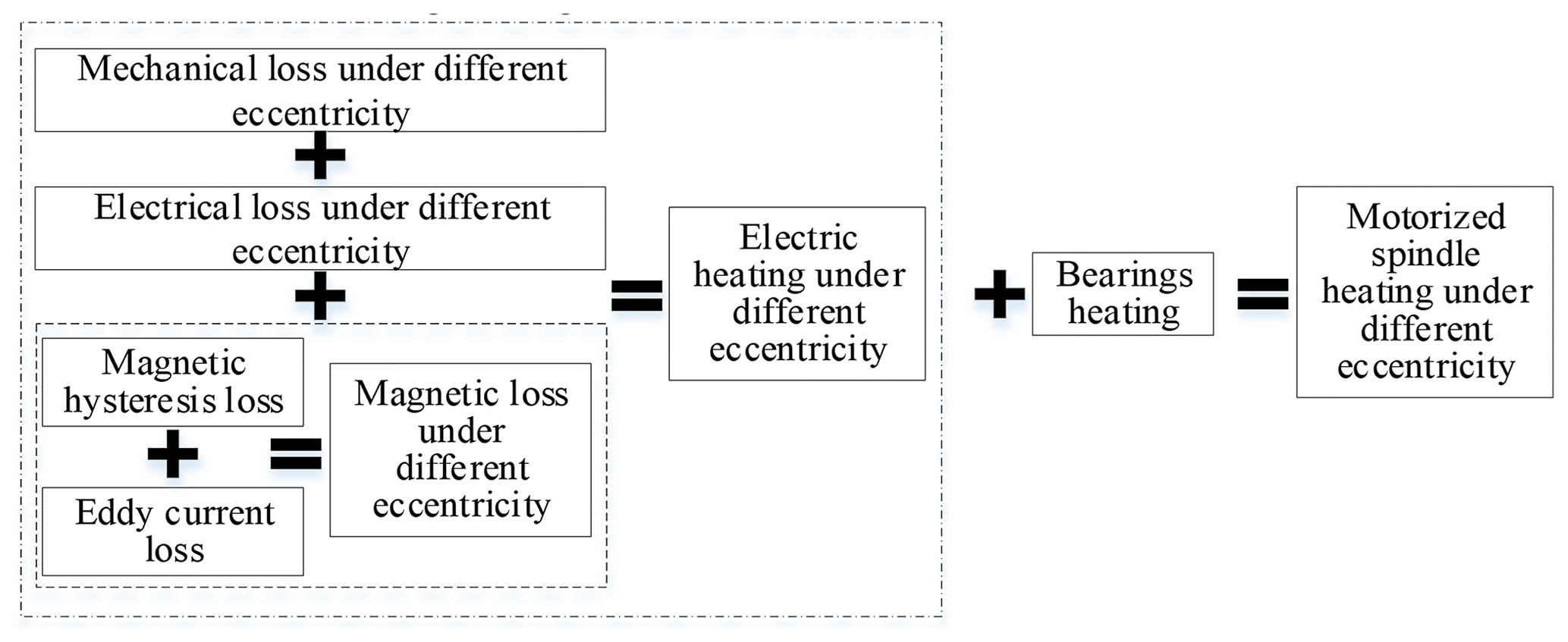
As shown in Fig. 2, the motorized spindle heating model with different rotation speeds is constructed from the collection of each motor loss and bearing heating under different eccentricities.
2.3 Simulation parameters of the motorized spindle heating considering air-gap eccentricity
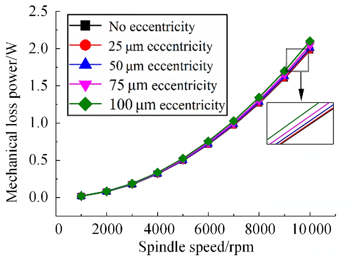
According to the above calculation model, the temperature field simulation parameters of the motorized spindle under different air-gap eccentricity are calculated. Since the theoretical average air gap between the stator and rotor of the motorized spindle is 300 µm, the mechanical power loss, electrical loss, and magnetic loss varying with rotating speed under the eccentricity of 0, 25, 50, 75 and 100 µm are calculated, respectively.
The calculation results of mechanical loss are shown in Fig. 3. The mechanical loss increases with the increase in rotating speed and eccentricity, and it increases more obviously with the increase in eccentricity at the same speed.
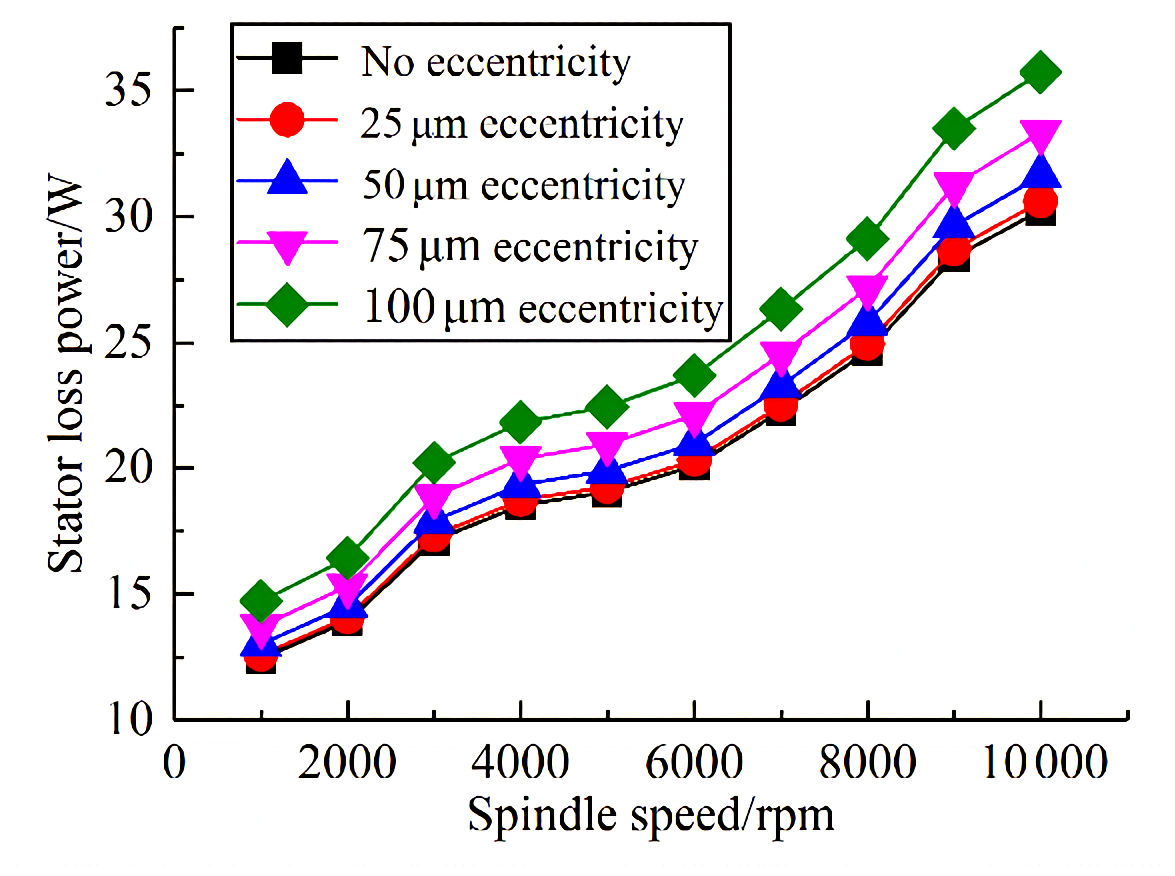
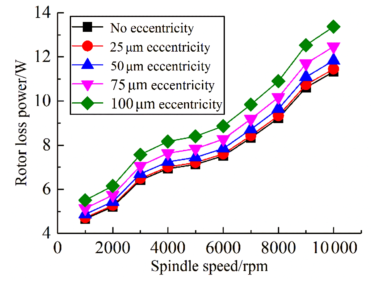
The electrical loss of the stator and rotor under different eccentricities varies with the rotating speed as shown in Figs. 4 and 5. The electrical loss increases with the increase in rotating speed and eccentricity. It can be seen from the figures that the greater the air-gap eccentricity is at the same speed, the more obvious the variation of the electric loss of the stator and rotor is. Therefore, the influence of air-gap eccentricity on the electrical loss is not negligible.
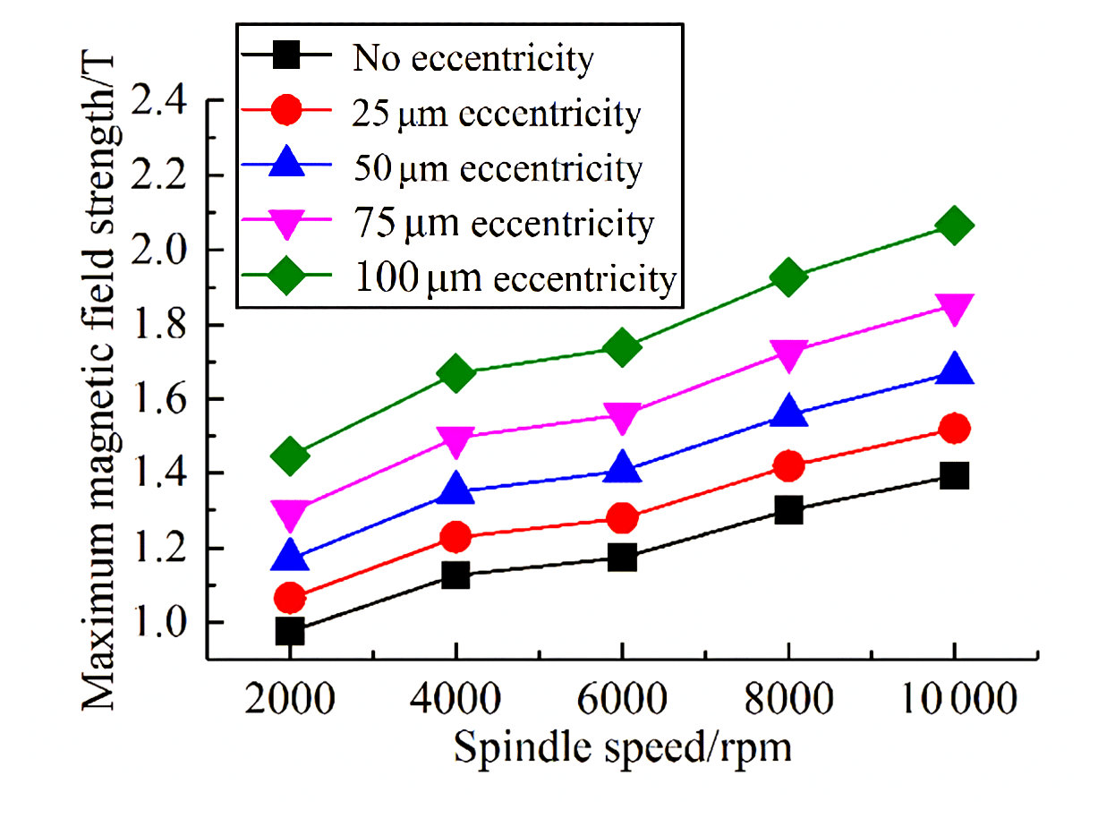
The maximum magnetic field strength under different eccentricities obtained by calculation is shown in Fig. 6. At the same rotation speed, the maximum magnetic field strength increases with the increase in eccentricity compared with the situation without eccentricity. The maximum magnetic field intensity increases by 9.09 %, 19.91 %, 32.81 % and 48.15 %, respectively, when air-gap eccentricity is 25, 50, 75 and 100 µm.
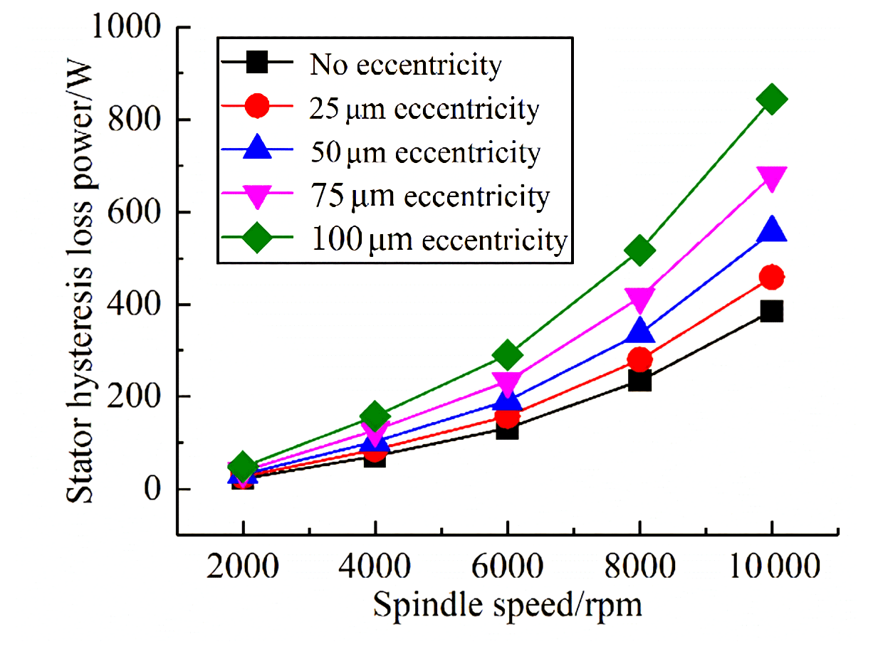
The hysteresis loss of the motor stator is proportional to the square of the maximum magnetic field strength. Therefore, the stator hysteresis loss varies with the variation of air-gap eccentricity, which is shown in Fig. 7. The stator hysteresis loss increases with the increase in rotating speed under the same eccentricity, and it changes significantly with the increase in rotating speed.
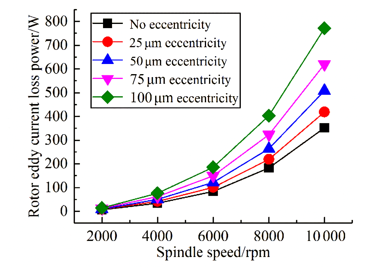
The eddy current loss of the stator and rotor is also closely related to the maximum magnetic field strength. It varies with the air-gap eccentricity too. The calculated eddy current loss of the stator and rotor with different eccentricities varies with the rotation speed, as shown in Fig. 8 and 9. The greater the eccentricity is, the greater the eddy current loss is, and the eddy current loss increases faster and faster with the increase in eccentricity.
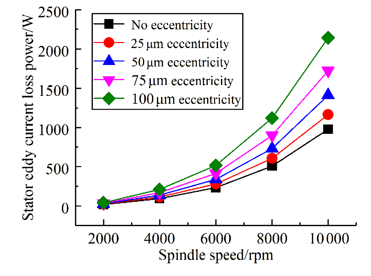
Figure 8The stator eddy current loss power with different rotating speed and eccentricities.
According to the motor loss power under different eccentricity and bearing heating power, the overall heating power of the motorized spindle with different eccentricities at each speed is obtained. As shown in Fig. 10, the overall heating power of the motorized spindle increases with the increase in eccentricity, and the higher the rotating speed, the more obvious the increase in heating power with eccentricity.
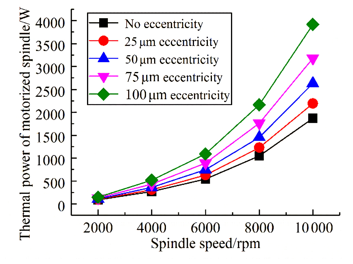
Figure 10Thermal power of the motorized spindle under different eccentricities of each speed.
3.1 Temperature field simulation of the motorized spindle without eccentricity
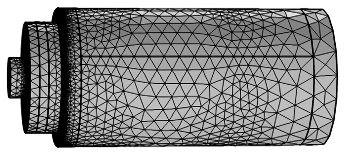
The 3D model of the motorized spindle is established by SolidWorks, and the minor components and small structure of the motorized spindle are simplified to simplify calculation. Based on the specific structure of the model and the solution requirements, a three-node triangular element is selected to mesh the bearings, the stator and rotor, rounded corners and mating surfaces. The divided model has a total of 147 511 nodes and 65 428 units, as shown in Fig. 11. The initial conditions are as follows: the ambient temperature is 16 ∘C; the coolant temperature is 16 ∘C; the coolant flow is 10 L min−1.
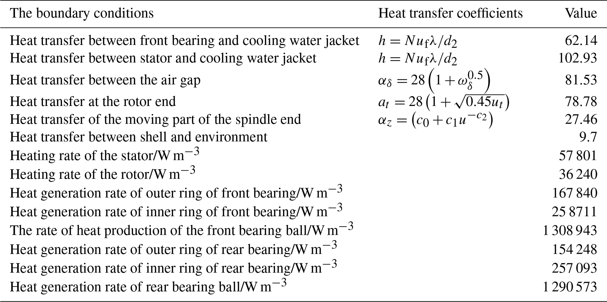
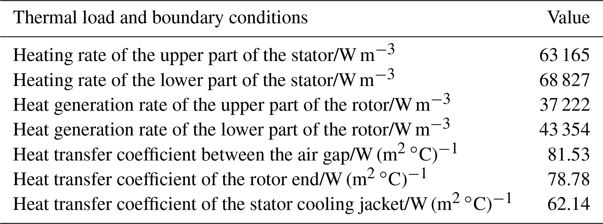
According to the theory of heat transfer, there are three basic modes of heat transfer, namely heat conduction, heat convection and heat radiation (Minkowycz et al., 2015). Because in the actual working conditions the radiation heat transfer is very little, only thermal conduction and convection of the motorized spindle are considered here. Taking 2000 rpm as an example, the relevant thermal model parameters and boundary conditions are shown in Table 1. In Table 1, λ is the thermal conductivity. ωδ is the average air-gap velocity. ut is the circumferential velocity of the rotor end. c0, c1 and c2 are constants measured in the experiment, 9.7, 5.33 and 0.8, respectively. Based on the finite-element method, the steady-state temperature field is simulated at 2000, 4000, 6000, 8000 and 10 000 rpm, respectively.
Table 1Thermal boundary conditions and thermal model parameter.
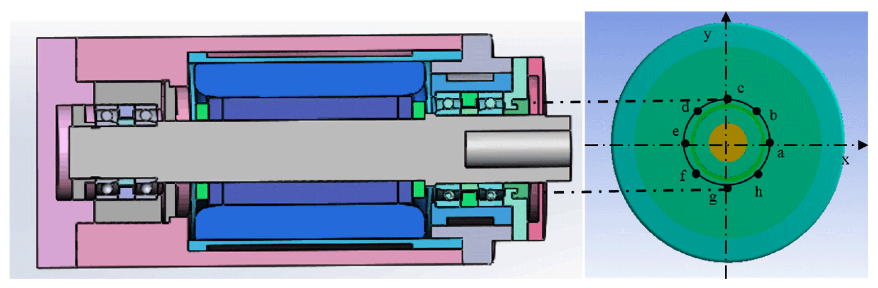
According to the structure and heat-transfer characteristics of the motorized spindle, the circle corresponding to the front-end cover is selected as circle 1 to analyze the distribution of the circumferential temperature field at different rotating speeds. In order to facilitate the analysis, the center of circle 1 is taken as the origin, and the rectangular coordinate system is established. The positions of eight measuring points are shown in Fig. 12.
Because the influence of air-gap eccentricity is not considered in the simulation, the circumferential steady-state temperature field at each speed obtained by simulation is relatively uniform and in a symmetrical state.
The steady-state temperature field simulations at 2000, 4000, 6000, 8000 and 10 000 rpm are obtained. The circumferential steady-state temperature field of each measuring point of circle 1 at different rotating speeds is shown in Fig. 13. Because the influence of air-gap eccentricity is not considered in the simulation, the circumferential steady-state temperature field at each speed obtained by simulation is relatively uniform and in a symmetrical state.
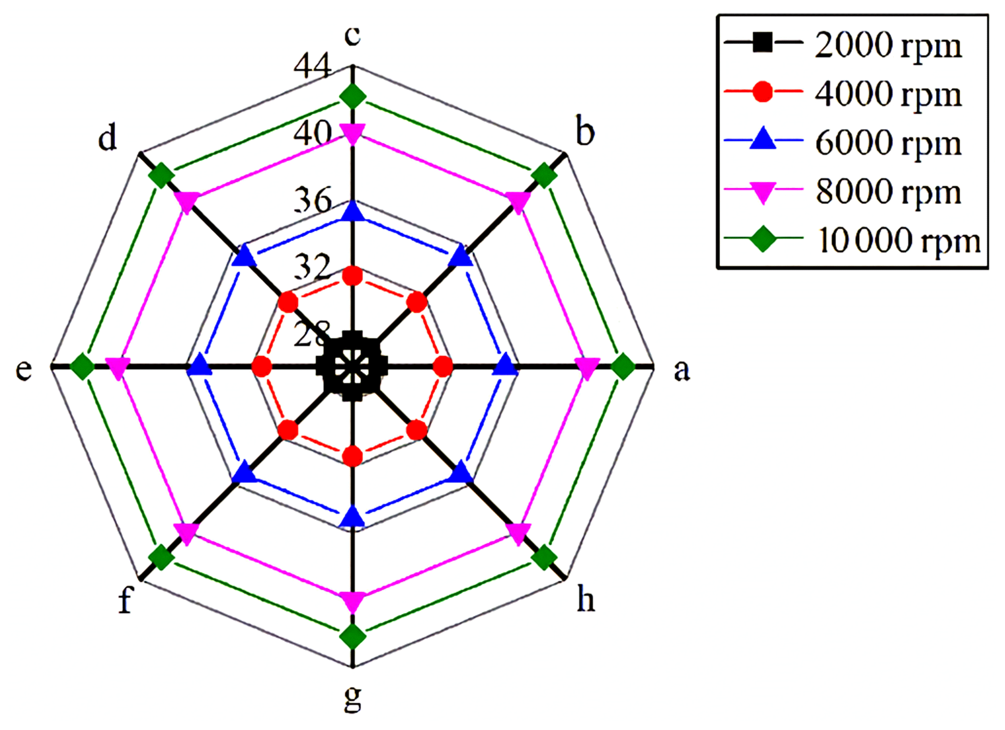
Figure 13Circumferential steady-state temperature field distribution of circle 1 at different rotating speeds.
3.2 Temperature field simulation of the motor considering eccentricity
It is assumed that the lowest part of the motor is the minimum air-gap position. The end surface temperature field of the motor under 0, 25, 50, 75 and 100 µm air-gap eccentricity is obtained. The positions of the minimum air-gap eccentricity and maximum air-gap eccentricity are named the lower half and upper half, respectively. The simulation boundary conditions of 25 µm eccentricity are shown in Table 2.
3.3 Analysis of simulation results considering air-gap eccentricity
Firstly, the overall temperature field distribution of the stator and rotor without air-gap eccentricity and with different eccentricity values is analyzed, and Fig. 14 shows part of the results. At 2000 rpm, the maximum temperature is 25.67 and 32.409 ∘C, respectively, when the air-gap eccentricity of the motor is 25 and 100 µm. Compared with the non-eccentric state, the temperature increases by 5.33 % and 32.99 %, respectively, which is consistent with the calculation in the previous chapter. With the increase in air-gap eccentricity, the loss of the motor increases gradually, which leads to the increase in temperature rise of the stator and rotor. Further, the circumferential temperature field of the stator and rotor also presents a non-uniform state.
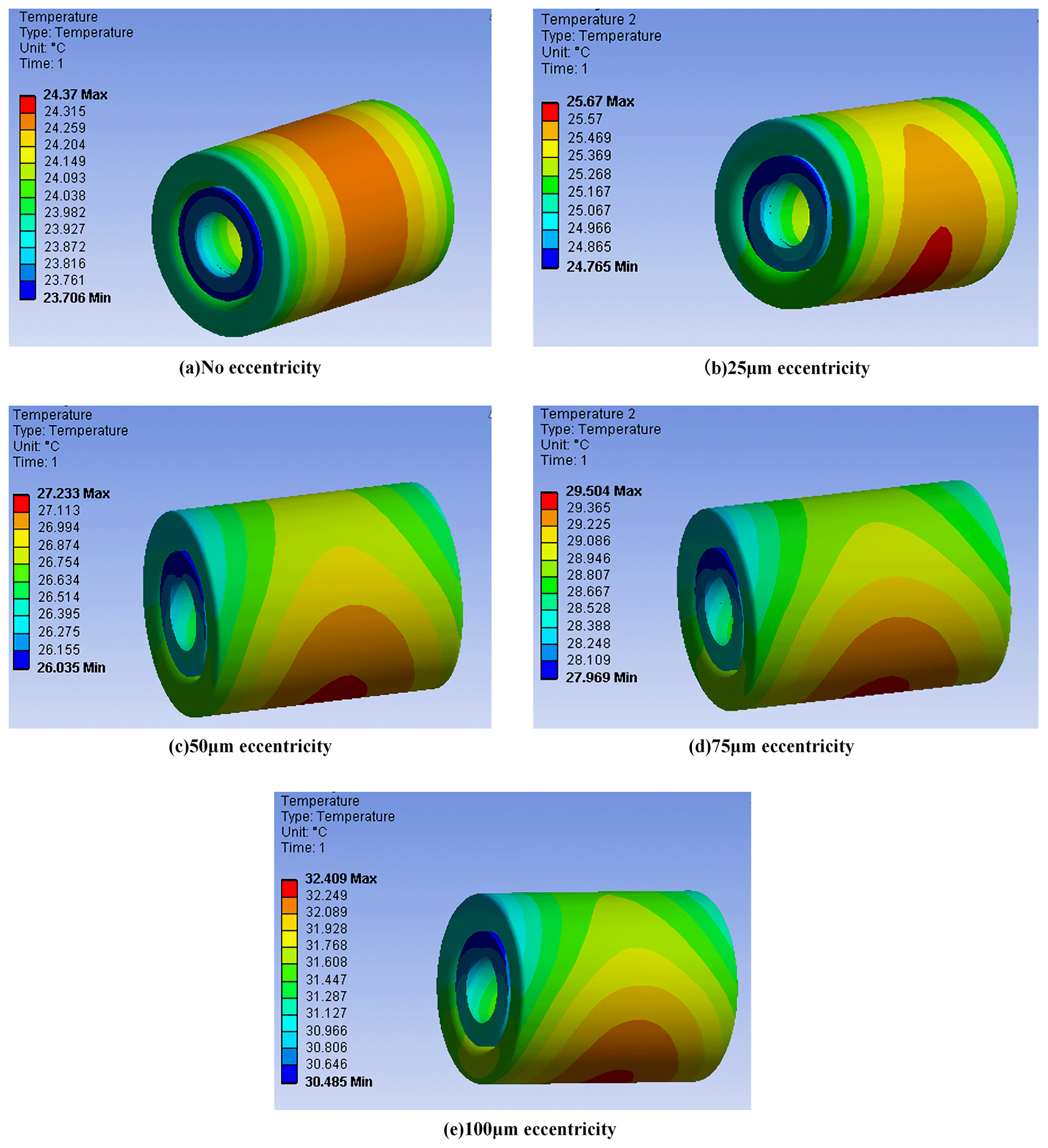
Figure 14The influence of air-gap eccentricity at 2000 rpm on the temperature field of the stator rotor.
The circumferential temperature of the stator and rotor in the different air-gap position is shown in Fig. 15. At the smallest air-gap position, the motor generates more heat. Therefore, the temperature of the stator and rotor is highest in this position, which is 31.658 ∘C of the stator and 31.215 ∘C of the rotor. The temperature of the motor decreases with the increase in air-gap length. This will result in asymmetric distribution of the circumferential temperature field between the stator and rotor, and there is a large temperature difference between the stator and rotor, 0.703 and 0.585 ∘C, respectively.
The maximum circumferential temperature difference of the stator end surface under different eccentricities is shown in Table 3. When the air gap is evenly distributed, the circumferential temperature field of the stator is evenly distributed. When the air-gap eccentricity is 25, 50, 75 and 100 µm, the maximum temperature difference of the stator circumferential temperature field is 0.173, 0.342, 0.519 and 0.703 ∘C, respectively. With the increase in air-gap eccentricity, the maximum temperature difference in the circumferential direction of the stator increases gradually; that is, the degree of non-uniformity in the circumferential temperature field increases.
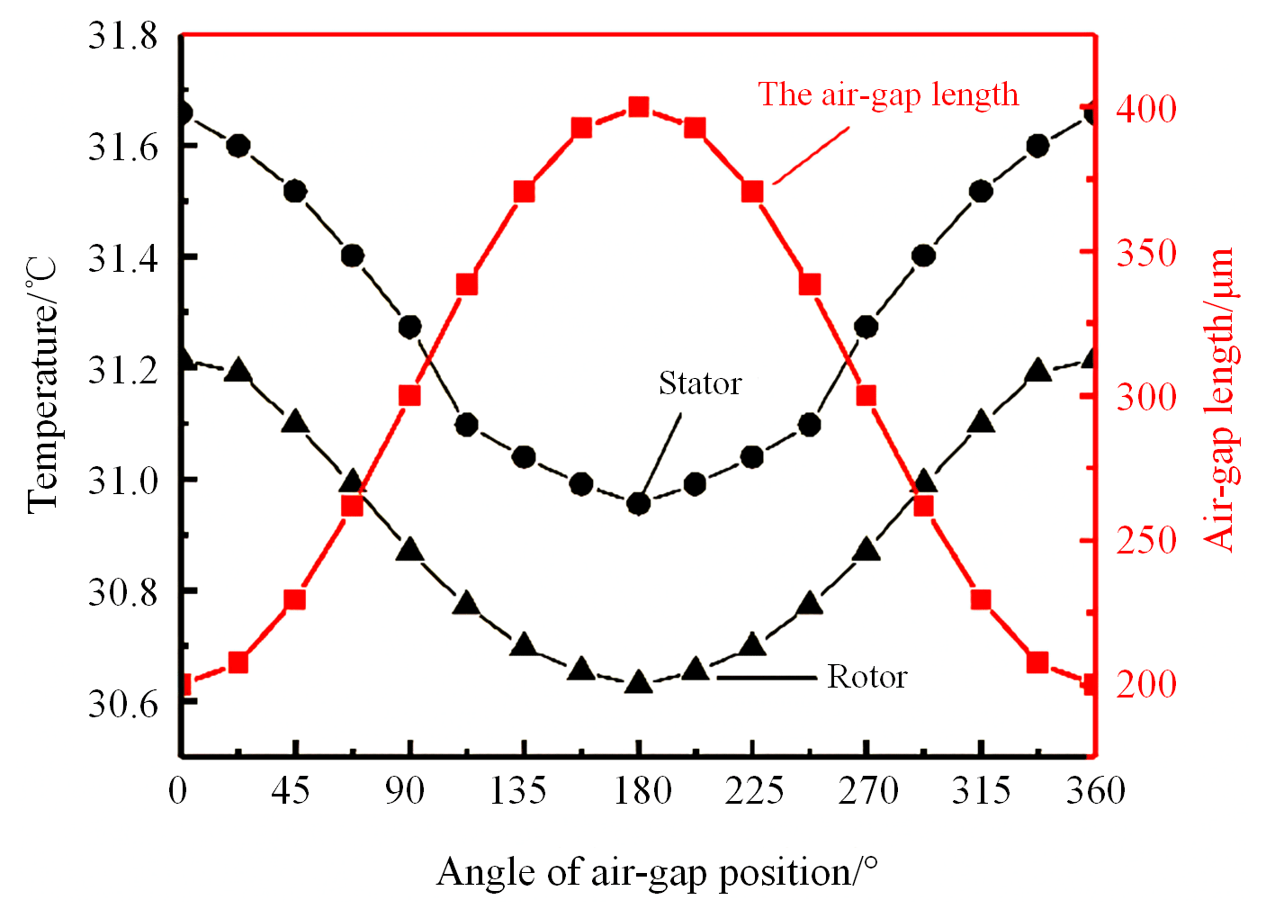
Figure 15The temperature of the stator and rotor with 100 µm eccentricity at different air-gap positions.
Table 3The circumferential maximum temperature difference of the stator under different air-gap eccentricity.

4.1 Design of experimental scheme
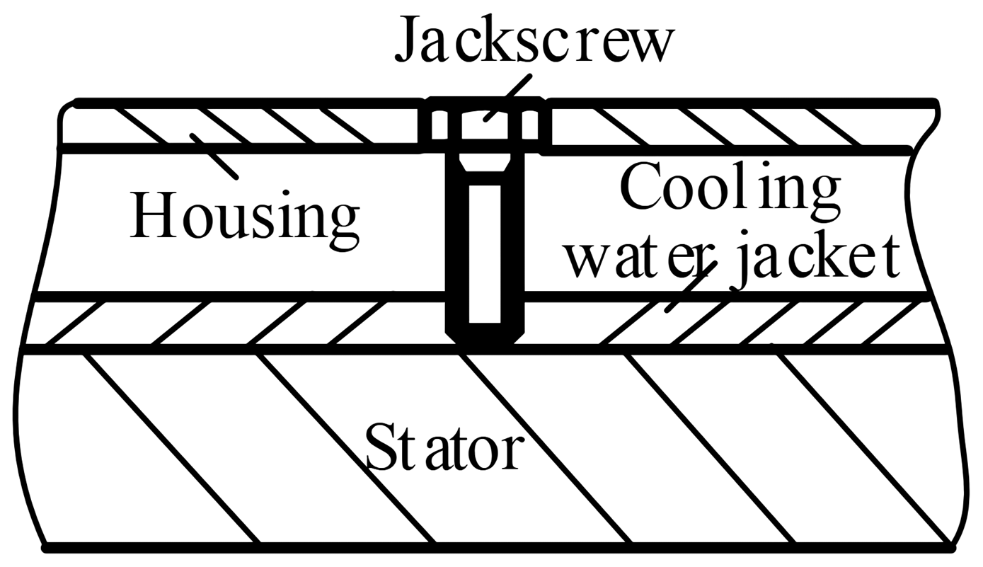
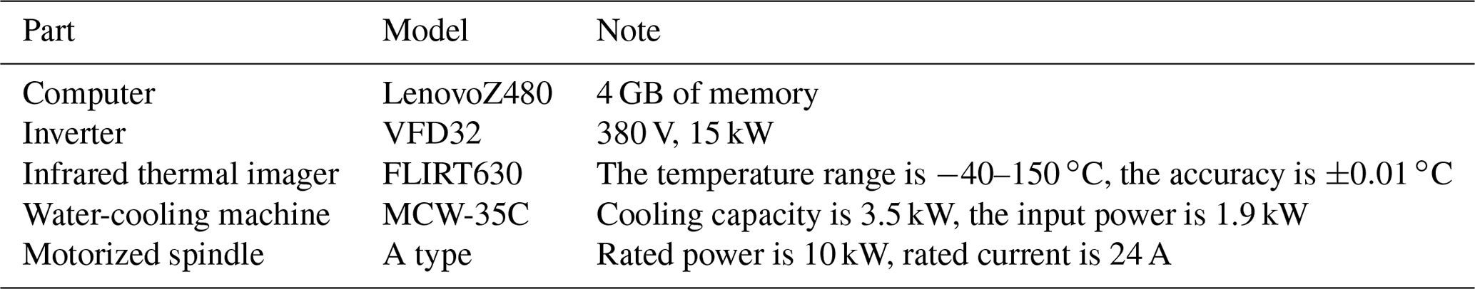
In order to verify the accuracy of the temperature field simulation of the motorized spindle and explore the actual distribution law of the temperature field of the motorized spindle, a non-contact motorized spindle temperature test bed with static eccentricity is built. The motorized spindle is produced by the Luoyang Bearing Research Institute. The air-gap eccentricity in the initial assembly of the motorized spindle is ensured by the top wire at the stator housing position (as shown in Fig. 16). Since the air gap of the motorized spindle used in our experiment is required to be 300 µm, the static eccentricity is set to about 100 µm, and the static eccentricity measured by the air-gap gauge is 90 µm. The experimental system includes infrared thermography, a frequency converter, a water-cooling machine and a control system. A frequency converter is used to control spindle-rotating speed and display frequency and current. The water-cooling machine is used to provide a fixed flow of circulating coolant and display the coolant-setting temperature, real-time temperature and ambient temperature. Each device is shown in Table 4.
The physical diagram of the motorized spindle temperature test bed and the overall structure layout are shown in Fig. 17.
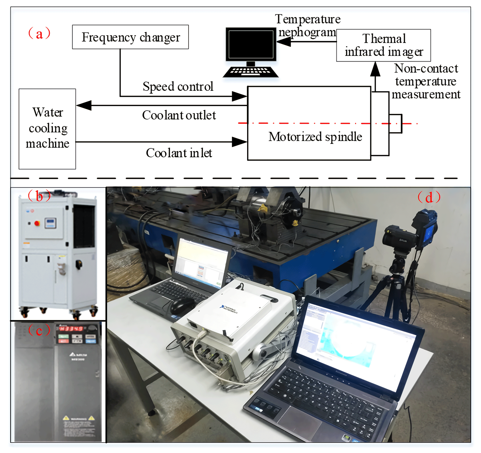
Figure 17Experimental system principle and object diagram. (a) Schematic diagram of experimental design. (b) Water-cooling machine. (c) The inverter. (d) Experimental system structure diagram.
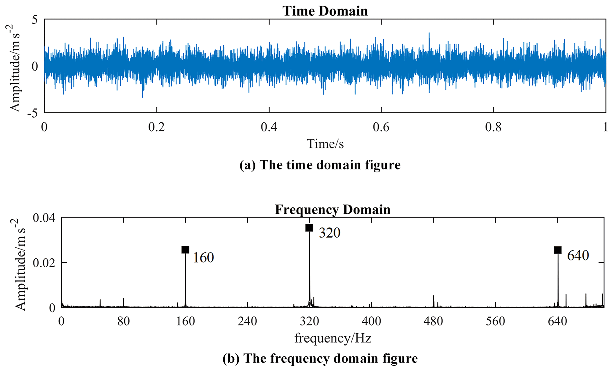
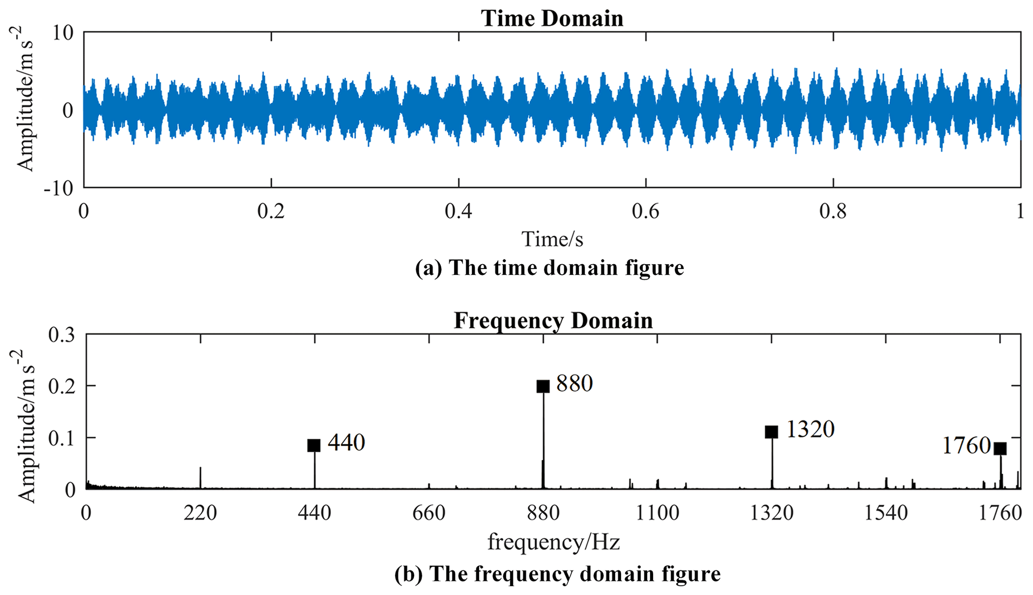
The vibration signal measured by the experiment can be used to detect the eccentric state of the motor (Li et al., 2007). In order to determine whether there is eccentricity in the initial assembly of the motorized spindle, the vibration tests of the motorized spindle at 4800 and 13 200 rpm were carried out by using the B&K data acquisition instrument and a three-way acceleration sensor. Its vibration signal and spectrum diagram after fast Fourier transform are shown in Figs. 18 and 19. The air-gap eccentricity of the motorized spindle will cause unbalanced magnetic tension and thus produce vibration of a different frequency. When its static eccentricity exists, the unbalanced magnetic tension will cause the vibration of the motorized spindle with a frequency of 4 times for the motorized spindle with two pole pairs. As can be seen from the figure, the corresponding 4-fold frequency conversion amplitude is large at different speeds, while other frequency conversion is relatively small. It shows that the initial assembly of the motorized spindle has a certain static eccentricity.
Taking the temperature field of the motorized spindle under no load as the main part, the motorized spindle temperature test bed is used to comprehensively explore the steady-state temperature field distribution of the motorized spindle end surface at different speeds (2000, 4000, 6000, 8000 and 10 000 rpm). The setting parameters of the infrared thermal imager are 1 m away from the object, 50 % relative humidity, and 0.95 sensitivity. The initial conditions of this group of experiments are consistent with those of simulation experiments.
4.2 Analysis of experimental results
The temperature field cloud diagram of the motorized spindle end surface at 2000 rpm and different times is shown in Fig. 20. The end surface temperature field presents a non-uniform phenomenon at 10 min through analysis. With the increase in time, the non-uniform state gradually deepens until the initial thermal equilibrium state is reached at 40 min.
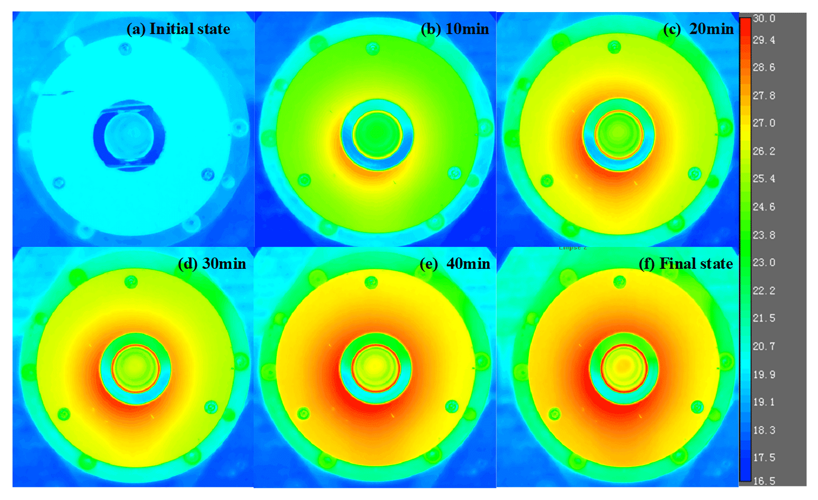
Figure 20Transient temperature field distribution at different times of the motorized spindle at 2000 rpm.
Table 5The maximum temperature difference of circle 1 at different rotating speeds.

In the corresponding part of the front-end cover, circle 1 is selected to study the distribution rule of the circumferential temperature field at different rotating speeds. The circumferential steady temperature fields of each measuring point on circle 1 at each rotating speed are shown in Fig. 21. The maximum temperature appears at point g at each rotating speed (except 10 000 rpm). For example, at 2000 rpm, the maximum temperature is 29.623 ∘C at point g and the minimum temperature is 28.158 ∘C at point c. Overall, the circumferential temperature field of circle 1 in operation is not uniform, and the non-uniform state of each rotating speed is that the temperature of the lower part is higher than that of the upper part. This is consistent with the simulation of temperature distribution considering air-gap eccentricity. There are two reasons for this analysis. Firstly, in terms of heat dissipation, the heat-dissipating capacity of each component is uneven. So, the thermal expansion is not uniform. Further, with the working clearance changing, the circumferential thermal resistance also changes. These will lead to the spindle circumferential temperature field in an asymmetric state. Secondly, the existence of air-gap eccentricity in the motor leads to non-uniform heating power in terms of heat generation. High heat generated at small air gaps leads to higher temperature. As a result, the temperature of the lower part of the stator and rotor is higher and the circumferential temperature field presents a non-uniform state. Heat from the stator and rotor is transferred to the end cover along the axial direction, which leads to the non-uniform temperature field in the circumferential direction of the front-end cover. In addition, the air-gap eccentricity of the motor will also make the temperature of the stator and rotor increased.
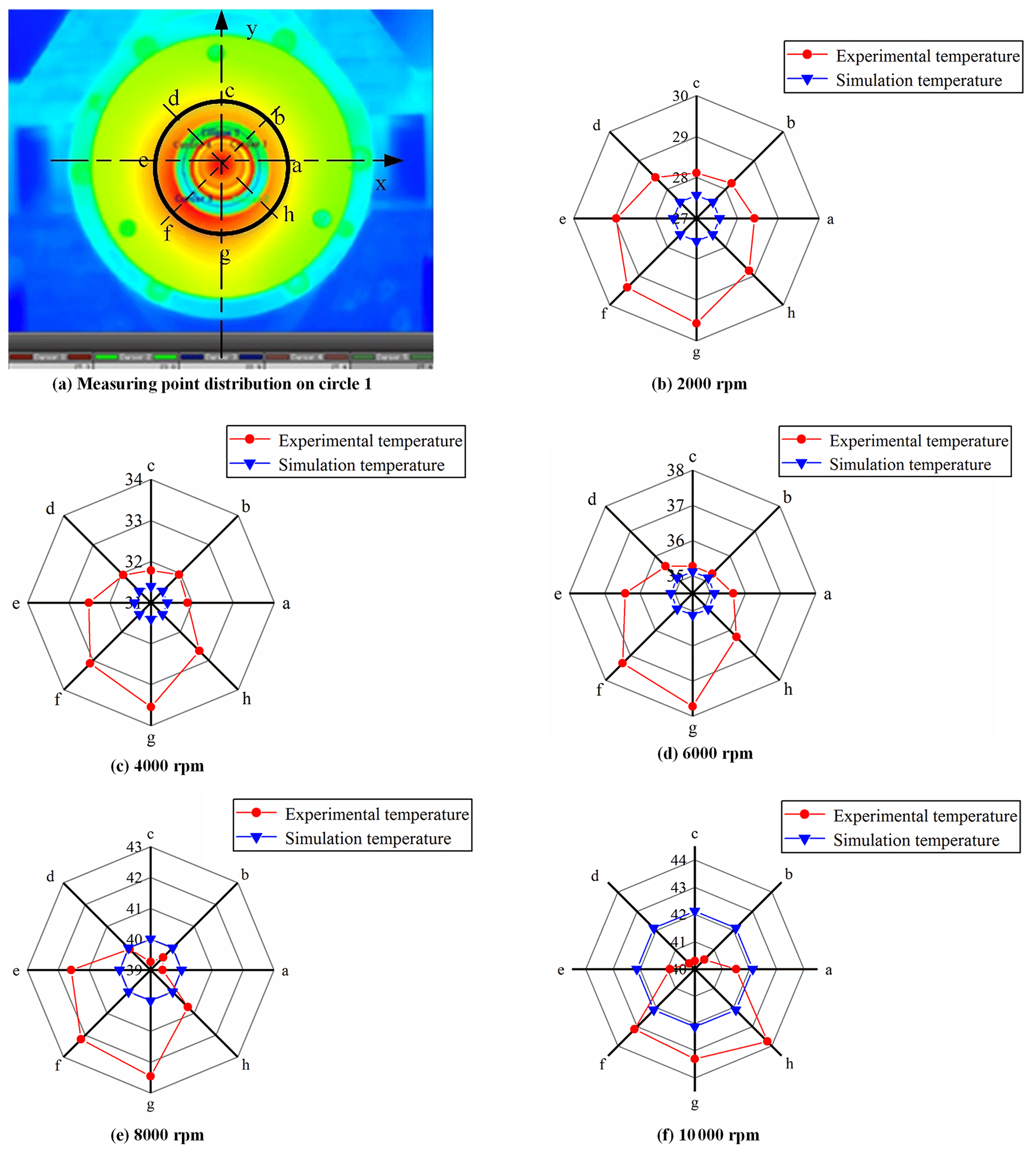
Suppose the maximum temperature of the circumferential temperature field is Tmax and the minimum temperature is Tmin. Then the circumferential maximum temperature difference is calculated by .
The degree of non-uniformity is expressed by the circumferential maximum temperature difference. The maximum temperature difference at each rotation speed on circle 1 is shown in Table 5. The maximum temperature difference increases from 1.465 to 3.468 ∘C with the increase in rotating speed. It indicates that the non-uniformity at circle 1 gradually deepens with the increase in rotating speed. The reason is the same as the calculated power loss trend of the motor. With the same eccentricity, each power loss of the motor increases significantly with the increase in rotating speed, and the loss difference at different circular positions is more obvious. Therefore, its circumferential non-uniformity deepens.
In this paper, based on the established thermal model, the influence of air-gap eccentricity on the temperature field distribution of a motorized spindle was studied and the circumferential temperature field distribution of the motorized spindle was revealed. The conclusions are as follows.
In the study of thermal model, mechanical loss, electrical loss and magnetic loss of the motor all increase with the increase in air-gap eccentricity. The mechanical loss power of 100 µm eccentricity increased by 6.31 % compared with that without eccentricity at 2000 rpm. The electric loss of the stator and rotor increased by 18.03 % and 18.04 %, respectively. Stator hysteresis loss increased by 1.17 times. The eddy current loss power of the stator and rotor increased by 1.19 times. It indicates that air-gap eccentricity has a great influence on motor loss. Therefore, air-gap eccentricity should not be neglected in the establishment of the thermal model.
Based on the finite-element method, the steady-state temperature field simulation study of the motorized spindle was conducted without considering air-gap eccentricity. The results show that the circumferential temperature field distribution is symmetrical, and the results of the temperature field after considering air-gap eccentricity show that the increase in air-gap eccentricity leads to the increase in temperature rise of the stator and rotor. Further, the temperature is higher at smaller air gap, and the circumferential temperature field is in a state of asymmetric distribution, and with the increase in eccentricity, the degree of non-uniformity increases up to 0.703 ∘C.
The steady-state temperature field experimental results of the motorized spindle at various rotating speeds show that the circumferential temperature field of the end cover is non-uniform, and the non-uniform state at each rotating speed is that the temperature of the lower half is higher than that of the upper half. It is consistent with the simulation results of temperature field considering air-gap eccentricity. The degree of non-uniformity gradually deepens with the increase in rotating speed.
This paper provides a theoretical basis for the accurate thermal characteristic analysis and the improvement of machined surface quality of the motorized spindle.
All the data used in this paper can be obtained from the corresponding author upon request.
XL proposed the research route and completed the first draft; JL modified and improved the paper and supplemented relevant data; CL completed part of the experiment and data analysis; JH provided guidance for the experiment and paper framework; DW provided guidance and analysis for replenishing experimental data.
The authors declare that they have no conflict of interest.
This article is part of the special issue “Robotics and advanced manufacturing”. It is not associated with a conference.
The authors express their gratitude for the financial support mentioned below.
This work was supported by the National Natural Science Foundation of China (grant nos. 52075428 and 51575434), the Major Science and Technology projects of Shaanxi Province of China (grant no. 2018zdzx01-02-01HZ01) and the Open Fund funded project of Henan Key Laboratory of High-Performance Bearing Technology (grant no. 2020ZCKF04).
This paper was edited by Peng Li and reviewed by Wei Wang and one anonymous referee.
Abdi, S., Abdi, E., and Mcmahon, R. A.: A study of rotor eccentricities effects on brushless doubly fed machines performance, in: 2015 IEEE International Electric Machines & Drives Conference (IEMDC), IEEE, Cordaron, Idaho, USA, 10–13 May 2015, 66 pp., 2015.
Bindu, S. and Thomas, V. V.: Detection of Static Air-Gap Eccentricity in Three-Phase Squirrel Cage Induction Motor Through Stator Current and Vibration Analysis, Advances in Power Systems and Energy Management, 436, 511–518, https://doi.org/10.1007/978-981-10-4394-9_50, 2018.
Bossmanns, B. and Tu, J. F.: A thermal model for high speed motorized spindles, Int. J. Mach. Tool. Manu., 39, 1345–1366, https://doi.org/10.1016/S0890-6955(99)00005-X, 1999.
Bossmanns, B. and Tu, J. F.: A Power Flow Model for High Speed Motorized Spindles – Heat Generation Characterization, J. Manuf. Sci. E.-T. ASME, 123, 494–505, https://doi.org/10.1115/1.1349555, 2001.
Chen, X. A., Zhang, P., He, Y., and Liu, J. F.: Power Flow Model of High-speed Motorized Spindles and its Thermal Characteristics, Transactions of the Chinese Society of Agricultural Machinery, 44, 250–254, https://doi.org/10.6041/j.issn.1000-1298.2013.09.043, 2013.
Ding, S. Y., Jiang, S., Wang, M. Q., Guan, T. Y., and Cui, G. H.: Influence of rotor eccentricity on magnetic density and core loss for induction motors, IEEE International Conference on Applied Superconductivity & Electromagnetic Devices (ASEMD), Shanghai, China, 20–23 November 2015, 316–317, 2015.
Ellison, A. J. and Yang, S. J.: Effects of rotor eccentricity on acoustic noise from induction machines, P. I. Electr. Eng., 118, 174–184, https://doi.org/10.1049/piee.1971.0028, 1971.
Guo, D., Chu, F., and Chen, D.: The Unbalanced Magnetic Pull and its Effects on Vibration in a Three-phase Generator with Eccentric Rotor, J. Sound Vib., 254, 297–312, https://doi.org/10.3969/j.issn.1000-4750.2003.02.023, 2003.
Han, X. and Palazzolo, A.: Unstable force analysis for induction motor eccentricity, J. Sound Vib., 370, 230–258, https://doi.org/10.1016/j.jsv.2016.01.045, 2016.
Harris, T. A. and Kotzalas, M. N.: Advanced Concepts of Bearing Technology Rolling Bearing Analysis (Fifth Edition), CRC Press, Boca Raton, 368 pp., https://doi.org/10.1201/9781420006582, 2007.
He, Y. L., Deng, W. Q., Tang, G. J., Sheng, X. L., and Wan, S. T.: Impact of Different Static Air-Gap Eccentricity Forms on Rotor UMP of Turbogenerator, Math. Probl. Eng., 2016, 1–13, https://doi.org/10.1155/2016/5284815, 2016.
He, Y. L., Wang, F. L., Tang, G. J., Jiang, H. C., and Yuang, X. H.: Effect of Stator Inter-Turn Short Circuit Position on Electromagnetic Torque of Generator with Consideration of Air-Gap Eccentricity, Transactions of China Electrotechnical Society, 32, 11–19, https://doi.org/10.19595/j.cnki.1000-6753.tces.2017.07.002, 2017a.
He, Y. L., Wang, F. L., Tang, G. J., Liu, H. L., Deng, W. Q., and Wan, S. T.: Effect of Static Air-Gap Eccentricity on Electromagnetic Torque of Generator, Zhendong Ceshi Yu Zhenduan/Journal of Vibration, Measurement and Diagnosis, 37, 922–927, https://doi.org/10.16450/j.cnki.issn.1004-6801.2017.05.011, 2017b.
Kim, D. J., Kim, H. J., Hong, J. P., and Park, C. J.: Estimation of Acoustic Noise and Vibration in an Induction Machine Considering Rotor Eccentricity, IEEE T. Magn., 50, 857–860, https://doi.org/10.1109/TMAG.2013.2285391, 2014.
Li, X. D., Wu, Q., and Nandi S.: Performance Analysis of a Three-Phase Induction Machine with Inclined Static Eccentricity, IEEE T. Ind. Appl., 43, 531–541, https://doi.org/10.1109/TIA.2006.889806, 2007.
Mayr, J., Jedrzejewski, J., and Uhlmann, E., Donmez, M. A., Knapp, W., Hrtig, F., Wendt, K., Moriwaki, T., Shore, P., and Schmitt, R.: Thermal issues in machine tools, CIRP Ann.-Manuf. Techn., 61, 771–791, https://doi.org/10.1016/j.cirp.2012.05.008, 2012.
Minkowycz, W. J., Sparrow, E. M., and Murthy, J. Y.: Handbook of Numerical Heat Transfer: Second Edition, Drying Technology, John Wiley & Sons, Inc., Hoboken, New Jersey, 2015.
Oumaamar, M. E. K., Maouche, Y., Boucherma, M., and Khezzar, A.: Static air-gap eccentricity fault diagnosis using rotor slot harmonics in line neutral voltage of three-phase squirrel cage induction motor, Mech. Syst. Signal Pr., 84, 584–597, https://doi.org/10.1016/j.ymssp.2016.07.016, 2017.
Smith, C. F.: The irregularities in the rotating field of the polyphase induction motor, Journal of the Institution of Electrical Engineers, 46, 132–159, https://doi.org/10.1049/jiee-1.1911.0009, 1911.
Smith, C. F. and Johnson, E. M.: The losses in induction motors arising from eccentricity of the rotor, Journal of the Institution of Electrical Engineers, 48, 546–569, https://doi.org/10.1049/jiee-1.1912.0027, 1912.
Yan, K., Hong, J., Zhang, J. H., Mi, W., and Wu, W. W.: Thermal-deformation Coupling in Thermal Network for Transient Analysis of Spindle-bearing System, Int. J. Therm. Sci., 104, 1–12, https://doi.org/10.1016/j.ijthermalsci.2015.12.007, 2016.
- Abstract
- Introduction
- Motorized spindle heating model considering air-gap eccentricity
- Study on temperature field simulation of the motorized spindle considering air-gap eccentricity
- Experimental study
- Conclusions
- Data availability
- Author contributions
- Competing interests
- Special issue statement
- Acknowledgements
- Financial support
- Review statement
- References