the Creative Commons Attribution 4.0 License.
the Creative Commons Attribution 4.0 License.
 | 11 Jan 2021
Kinematic synthesis method and eccentricity effects of a Stephenson mechanism
Amandyk Tuleshov
Recep Halicioglu
Azhar Shadymanova
Moldir Kuatova
When implementing the technological process on crank presses, it is necessary to provide a predetermined working cycle of the slider motion: fast lifting, dwell, and slow lowering. The cycle cannot be realized without controlling the motor. In addition, using controllable motors increases the manufacturing cost. Due to the geometric and kinematic capabilities of the mechanism, changing the kinematics of the working link is the best choice. Thanks to the use of the Stephenson II mechanism, the slider skew is eliminated due to the parallel connecting rods and the increased area of slider contact. This study presents a numerical method for kinematic synthesis of the Stephenson mechanism that has kinematic advantages. The method is based on mean square deviation which is the minimizing of an objective function. Thanks to the proposed synthesis method, approximate dwell movement can be performed when the slider is on the bottom dead center. In this study, values of the crank length and parallel connecting rods' lengths, angular coordinates of the crank and connecting rods, and the eccentricity of the guide slider relative to the crank rotation axis were obtained. It is observed that eccentricity affects the lower forward and higher backward speed of the slider. The kinematic results of the slider movement are comparatively presented in this article.
- Article
(530 KB) - Full-text XML
- BibTeX
- EndNote


The main disadvantage of a four-bar slider-crank press scheme is the impossibility of ensuring a long dwell of a working slide and the irregularity of its stroke (Bocharev, 2008). This is not possible because there is no intermediate link between the drive crank and the connecting rod bonded with a slider. Jomartov et al. (2020) showed that a crank press based on the Stephenson mechanism allows solving many problems characterized by crank presses based on four-bar mechanisms. For example, to correct a slider deformation caused by parallel connecting rods, the contact area of the slider needs to be increased. By using a simplified structure, they tried to achieve a dwell motion on slider (Jomartov et al., 2019; Tuleshov et al., 2019; Drakunov et al., 2018).
The development of new designs of machinery mechanisms, including crank presses (Bocharev, 2008), begins with the solution of analysis and synthesis problems based on mathematical modeling. When implementing the technological process in crank presses, it is necessary to provide a predetermined cycle of the working slider movement: fast lifting (reverse stroke), dwell, and slow lowering (working stroke). In studies conducted on crank presses, there are two ways to achieve these goals. First, these properties can be realized by modifying the kinematic chain in a mechanism with one degree of freedom (1 DOF). Tuleshov and colleagues (Jomartov and Tuleshov, 2019; Jomartov et al., 2019; Tuleshov et al., 2019; Jomartov and Tuleshov, 2018) presented an application of the four-class kinematic chain (structure group) to perform the synthesis of the crank press mechanism. The method of kinematic analysis of two connecting rod crank presses was developed by Jomartov et al. (2020) based on four-bar mechanism (Jomartov and Tuleshov, 2019). The second way is to solve this problem through the additional freedom of kinematic chain, which is called the hybrid press system (Kütük and Dülger, 2016; Tokuz, 1992; Dülger and Kireçci, 1995, 1999). Kütük and Dülger (2016) presented a scientific literature review on the analysis and synthesis of the hybrid mechanisms of the crank press. To provide a technological cycle, they studied a seven-bar mechanism that had 2 DOF and whose one degree was driven by a constant speed direct current power motor (for the implementation of the main technological process) and whose second degree was driven by a servomotor. In many other studies, hybrid press systems based on five-bar and seven-bar mechanisms with two degrees of freedom have been examined. A similar technology was carried out by Tokuz, Dülger, and their colleagues in a hybrid configuration (Tokuz, 1992; Dülger and Kireçci, 1995, 1999). The constant speed motor and servomotor were combined by a differential gearbox, which subsequently drove the crank mechanism (Tokuz, 1992).
Yuan et al. (2005) investigated two different mechanisms whose DOF was two. Ouyang et al. (2004) proposed a five-bar linkage mechanism, which consisted of a constant velocity alternating current motor and a speed controller, a brushless alternating current servomotor and a gear servo amplifier, a shift encoder, a flywheel, and a belt. Zhang also proposed a hybrid five-bar mechanism with an adjustable link (Zhang, 2006).
Connor et al. (1995) conducted studies on the synthesis of five-bar hybrid mechanisms by using genetic algorithms. Dülger et al. (2003) carried out a study on modeling and kinematic analysis of a hybrid actuator of the seven-bar mechanism with a controllable crank. Yu (2006) performed a study by using the hybrid machine (HM) system with a five-bar mechanism. Li and Zhang (2010) applied a seven-bar configuration through kinematic analysis and optimal design of the hybrid system. Li and Tso (2008) introduced a seven-bar mechanism that was later used to study the performance of stamping and energy distribution between a servo motor and a flywheel with various motion inputs (Tso and Li, 2008). In addition, Tso (2010) also developed a control system for the seven-bar mechanism by using iterative training management and feedback control techniques.
In all above-mentioned mechanisms, the issue of providing the necessary slider motion cycle was solved by controlling two or more motors, and accordingly, the tasks of dynamic synthesis of drive control functions were achieved. The implementation of the technological cyclogram by a mechanism with one degree of freedom requires a significant complication of the structure linkage kinematic chain which is called the Assur group (Yevgrafov et al., 2006; Huang and Ding, 2020).
Metal-forming equipment is commonly based on the four-bar structural group mechanisms. However, six-bar structural group mechanisms, such as Stephenson II mechanisms, have broader functionality. In this study, an analytical kinematic synthesis method for a Stephenson mechanism that provides balancing was developed for metal-forming process. This synthesis was carried out based on the mean-square minimization of the objective function which was obtained taking into account the geometric features of the Stephenson mechanism structure. The effect of eccentricity was also investigated. Kinematic results were obtained by using the mathematical relations (position, speed, and acceleration). It was assessed that the eccentricity affected the possibility of ensuring the approximate slider dwell and the increase of the average slider velocity coefficient.
Figure 1 demonstrates the kinematic scheme of a simplified six-bar Stephenson mechanism. The feature of the mechanism is that the variable contour BB′C′C is a parallelogram and a triangle ABB′ is equilateral. In this figure, r, a, and l indicate crank length, ABB′ triangle height, and parallel connecting rods length of BC = B′C′, respectively. φ, ψ, S, e and b show the angle coordinate of a crank, angle coordinate of two connecting rods, linear coordinate of a slider, slider eccentricity (i.e., the deviation of a trajectory of a slider center gravity from the axis Oy), and distance between joint C and slider center along an axis Ox, respectively.
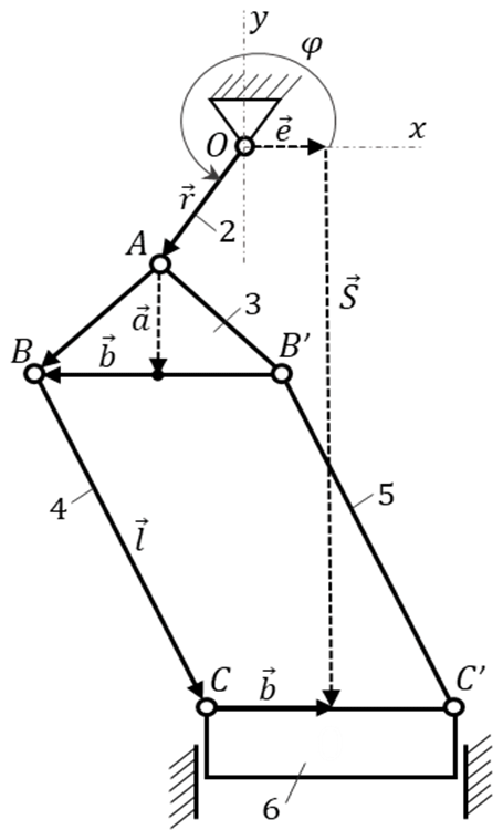
The kinematics of the Stephenson crank press mechanism have the following Eq. (1) (Jomartov et al., 2020):
A clear solution of Eq. (1) in relation to S=S(φ), ψ=ψ(φ) is obtained in Eq. (2) (the ± signs correspond to various assemblies of the mechanism):
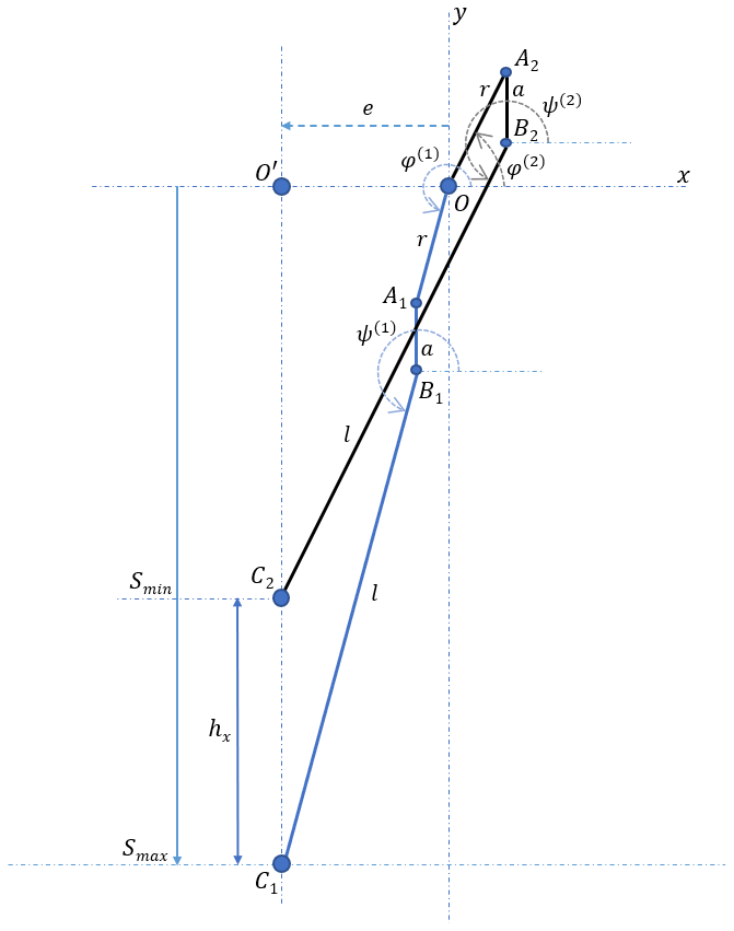
According to the scheme on Fig. 1, rods of 4 and 5 rotate around the joints C and C′ (l – radius of joints). The trajectories of joints B and B′ are a circle in the interval . It is necessary for the slider to work well. Equation (3) is a vector form of the mechanism scheme in Fig. 1. The scheme of the Stephenson press mechanism is based on vector Eq. (3) that is presented in Fig. 2.
3.1 Initial data
The origin of the x, y coordinate system is in the center of the rotation of the crank O. The slider stroke hx is considered as given. According to Fig. 2, when rod and crank are on parallel lines, the slider is in extreme positions. Considering the geometric positions, the following statements can be written:
By subtracting the first equation from the second, we obtain the slider stroke:
Given that φ(1)=ψ(1) and from Eq. (1), we have the following:
3.2 The method of the task solution
Based on Fig. 2, considering the geometric positions, the following statements can be written:
Then
or
When statements of are written on their places, Eq. (6) is obtained:
To find the parameters r, a, l, e, and φ0, which satisfy Eq. (5) and for all values, the following can be written:
After the transformations of Eq. (7),
or
which can be presented as
Here the following signs are inputted:
When the statements of , are written on their place, the following statements are obtained:
As a result, we get these ratios:
So, four required parameters of the crank press linkage mechanism determined by five parameters are P0, P1, P2, P3, and P4.
For compatibility condition of the solution, the following constraints must be applied:
According to Eq. (11), there are constraints between unknowns and we can use the method of an objective function of conditional optimization in Eq. (9) (Bertsekas, 1982). Then, by using Eq. (12), the Lagrange function can be obtained as an objective function as follows:
For determination of P0, P1, P2, P3, P4, and λ, the quadratic approximation method, which determines the sum of squared deviations minimum for N mechanism positions, is used (Jomartov and Tuleshov, 2018):
By taking the derivative of L with respect to Pj, the minimum conditions are given below:
Equation (16) presents a nonlinear equation set related to the required parameters:
The nonlinear set (16) has to satisfy minimum conditions (15). It is solved in relation to , and λ. From the solution set, the equation of is selected.
The required geometric parameters are found by using the following equations:
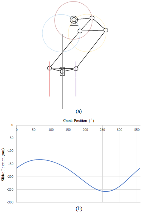
The mechanism's geometric parameters were obtained by using the proposed Stephenson II synthesis method. The Eq. (16) was solved for the mechanism's five positions, and the geometric parameters of the mechanism were determined by using Eq. (17). As a result, the mechanism dimensions that could meet the desired conditions were found with the proposed method. Table 1 shows the mechanism dimensions of the Stephenson crank press synthesized in this study. The kinematic scheme of the mechanism is presented in Fig. 3a, with the size of links: r=60 mm, φ0=260∘, l=160 mm, mm, when set mm and a=41 mm. By using these synthesized dimensions, the effects of dimension e (eccentricity) were studied additionally.

Numerical modeling programs were developed by the MAPLE® software. The kinematic results (position, speed, and acceleration results) were verified by ASIAN-2014® software.
Figure 3b presents a graph of slider movement. After crank angle passes 200∘, a movement close to dwell is seen in the interval of with an accuracy of Δ=0.063. Such accuracy was obtained by solving the nonlinear set (Eq. 16) in the first approximation.
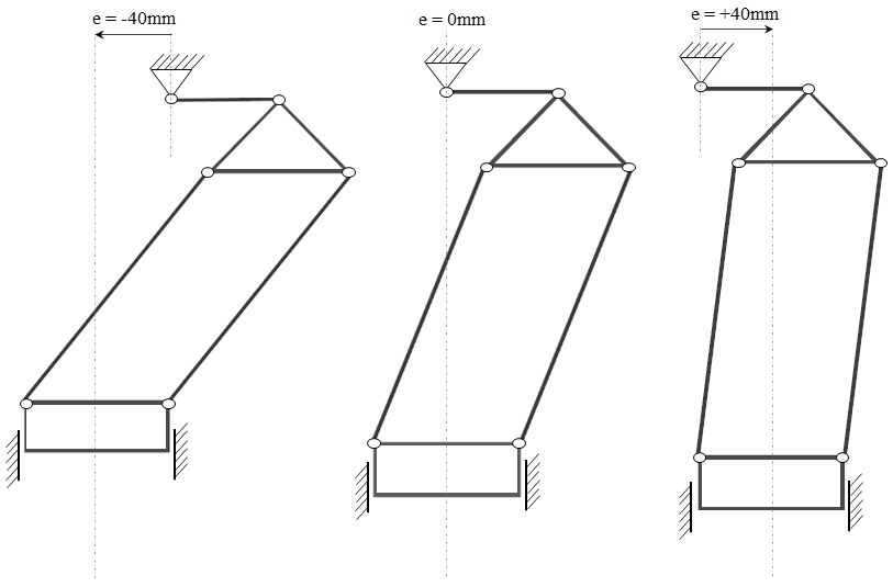
Figure 4 shows the three different eccentricity designs with e dimensions of −40, 0, and +40, respectively. The crank moves with a constant velocity, and Fig. 5 shows the crank angle versus time. This input was used for each simulation. Figure 6 presents the slider position versus time that changes with different eccentricity dimensions of e.

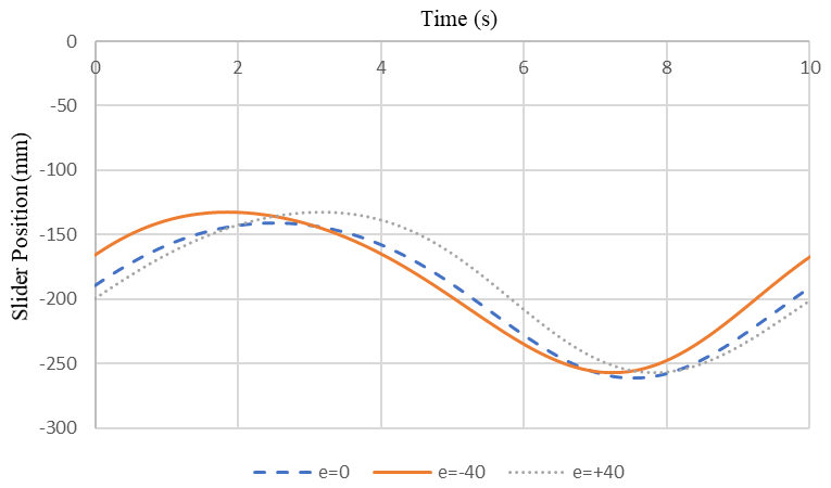
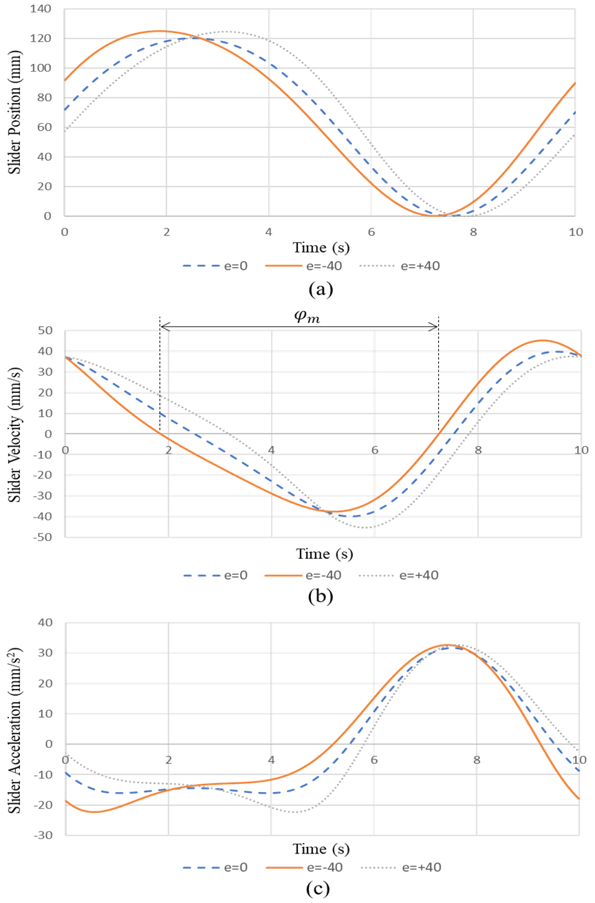
The bottom dead center of the slider was set to zero position. Figure 7 shows graphs of the set position, velocity, and acceleration of the working slider. It is observed that changing of eccentricity affects the kinematics of the Stephenson mechanism. The eccentricity of −40 provides slower forwarding and faster backwarding. While the similar maximum slider points are shown for each eccentricity, their start and end points are different as given in Fig. 7a.
An important parameter of the mechanism is the coefficient of increase of the average slider velocity:
where φm is crank rotation angle during the slider stroke; the crank rotates counterclockwise.
The velocity graph analysis in Fig. 7b allows determining the φm values at different eccentricity values: mm, e2=0, e3=40 mm. They are equal to ∘, ∘, ∘. When the values are substituted in Eq. (18), the average slider velocity coefficient values corresponding to eccentricity values are found as K1=1.18; K2=1.0; K3=0.847.
A slow lowering in the working stroke and fast lifting in the reverse stroke of the slider is significant in press tools. As shown in figures, this process is realized when mm and K1=1.18. The graph analysis in Fig. 7c shows that the slider acceleration at the forward stroke beginning is almost unchanged and noticeably accelerates at the end of the working process. This is common in all cases. The maximum velocity of 47 mm s−1 is reached at a maximum acceleration of 33 mm s−2 in 2 s, which is the cause of the shock load between the slider and the forging.
In this study, an analytical method for kinematic synthesis of linkage mechanisms based on the mean-square minimization of the objective function was developed. By taking into account the structural features of the mechanism, a method for deriving this objective function was proposed. Based on this method, algorithms were obtained, and Stephenson's press mechanism was synthesized. The crank length, two parallel connecting rods length, and the eccentricity of the slider relative to the axis of the crank rotation were found in an appropriate way. Eccentricity effects were also compared. The approximate slider dwell movement and the regulated coefficient of increase of the average slider velocity of the Stephenson II mechanism were achieved. It was seen that the coefficient of increase of the average slider velocity allowed regulating the technological process character and providing the desired cycle of the slider movement.
Data are available from the authors.
AT, RH, AS, and MK discussed and decided on the methodology in the study and prepared the manuscript. AT conceived and developed the kinematic synthesis of the mechanism. Kinematic modeling and analysis were performed by RH, who is the corresponding author. AS participated in the kinematic synthesis and analysis. MK participated in developing the kinematic scheme and coordinated helped to draft the manuscript.
The authors declare that they have no conflict of interest.
The authors would like to thank the Ministry of Education and Science of the Republic of Kazakhstan, the U. A. Joldasbekov Institute of Mechanics and Mechanical Engineering, and LLP “Semizbay-U” for their support.
This research has been supported by LLP “Semizbay-U” (agreement no. 478227-2/2020/1).
This paper was edited by Daniel Condurache and reviewed by three anonymous referees.
Bertsekas, D.: Constrained Optimization and Lagrange Multiplier Methods, Elsevier, Academic Press, USA, https://doi.org/10.1016/C2013-0-10366-2, 1982.
Bocharev, I. A.: Press forging equipment, Akademiia, Moscow, 2008 (in Russian).
Connor, A. M., Douglas, S. S., and Gilmartin, M. J.: The synthesis of hybrid five-bar path generating mechanisms using genetic algorithms, 1st International Conference on Genetic Algorithms in Engineering Systems: Innovations and Applications, 313–318, Galesia, 1995.
Drakunov, Y., Tuleshov, A., Jomartov, A., Tuleshov, E. A., Seidakhmet, A. Zh., Kayim, T. T., Ibrayev, S. M., Jamalov, N. K., Drakunov, A. Yu., and Drakunov, S. U.: Development of methods and technology of designing of power press-machines based on new crank operating mechanisms, National Center of Science and Technology Evaluation, Report No. 0218PK00926, 1–160, 2018 (in Russian).
Dülger, L. and Kireçci, A.: A study on a hybrid actuator, Mech. Mach. Theory, 35, 1141–1149, 1999.
Dülger, L. C. and Kireçci, A.: Hybrid Manipulator Modelling and Simulation, 7th National Machine Thery Symposium, YTU, Istanbul, 1995 (in Turkish).
Dülger, L. C., Kireçci, A., and Topalbekiroglu, M.: Modeling and simulation of a hybrid actuator, Mech. Mach. Theory, 38, 395–407, 2003.
Huang, P. and Ding, H.: Structural synthesis of Assur groups with up to 12 links and creation of their classified databases, Mech. Mach. Theory, 145, 103668, https://doi.org/10.1016/j.mechmachtheory.2019.103668, 2020.
Jomartov, A. and Tuleshov, A.: Vector method for kinetostatic analysis of planar linkages, J. Braz. Soc. Mech. Sci., 40, 1–9, https://doi.org/10.1007/s40430-018-1022-y, 2018.
Jomartov, A. and Tuleshov, A.: Modeling Dynamics of Planetary Gears of Crank Press on SimulationX, in: Advances in Italian Mechanism Science, edited by: Carbone, G. and Gasparetto, A., IFToMM ITALY 2018, Mechanisms and Machine Science, Vol. 68, Springer, Chamber, 41–48, https://doi.org/10.1007/978-3-030-03320-0_5, 2019.
Jomartov, A., Tuleshov, A., and Kuatova, M.: Designing of a Crank press on the Basis of High Class Planar Linkages, in: Advances in Mechanism and Machine Science, edited by: Uhl, T., IFToMM WC 2019. Mechanisms and Machine Science, Vol. 73, Springer, Chamber, 3027–3036, https://doi.org/10.1007/978-3-030-20131-9_298, 2019.
Jomartov, A., Tuleshov, A., Jamalov, N., Kuatova, M., and Kaimov, A.: Designing of the Stephenson II six-link linkage actuator for servo mechanical press, International Journal of Mechanical and Production Engineering Research and Development, 10, 501–512, https://doi.org/10.24247/ijmperdapr202053, 2020.
Kütük, M. E. and Dülger, L. C.: A hybrid press system: Motion design and inverse kinematics issues, Engineering Science and Technology, an International Journal, 19, 846–856, 2016.
Li, C. H. and Tso, P. L.: Experimental study on a hybrid driven press using iterative learning control, International Journal of Machine Tools and Manufacture, 48, 209–219, 2008.
Li, H. and Zhang, Y.: Seven bar mechanical press with hybrid driven mechanism for deep drawing; part 1: kinematics analysis and optimum design, part 2: dynamic modeling and simulation, J. Mech. Sci. Technol., 11, 2153–2160, 2161–2167, 2010.
Ouyang, P. R., Li , Q., and Zhang, W. J.: Design, modelling and control of a hybrid machine system, Mechatronics, 14, 1197–1217, 2004.
Tokuz, L. C.: Hybrid machine modelling and control, PhD thesis, Liverpool Polytechnic, 1992.
Tso, P. L.: Optimal Design of a Hybrid-Driven Servo Press and Experimental Verification, J. Mech. Design, 132, 034503, https://doi.org/10.1115/1.4000213, 2010.
Tso, P. L. and Li, C. H.: Study of servo press with a flywheel, J. Adv. Mech. Des. Syst., 2, 1–11, 2008.
Tuleshov, A. K., Jomartov, A. A., and Kuatova M. Zh.: The Model of The Movement of The Crank Press Based on The Lever Mechanism of the 4th Class, Annotations of reports of the 12th All-Russian Congress on fundamental problems of theoretical and applied mechanics, Russian Federation, Ufa, 2019 (in Russian).
Yevgrafov, M. Z., Semyonov, Y. A., and Slousch, A. V.: Theory of mechanisms and machines: a training manual, Academia, Moscow, 2006 (in Russian).
Yu, H.: Modeling and control of hybrid machine systems – a five-bar mechanism case, International Journal of Automation and Computing, 3, 235–243, https://doi.org/10.1007/s11633-006-0235-1, 2006.
Yuan, Z., Gilmartin, M.J., and Douglas, S.S.: Design of hybrid machines for nonuniform motion production, Proceedings of the Institution of Mechanical Engineers Pt. C, 219, 491–499, https://doi.org/10.1243/095440605X16992, 2005.
Zhang, K.: Optimization dynamics design of hybrid driving mechanisms, Proceedings of the 2006 IEEE International Conference on Mechatronics and Automation, 1914–1919, 2006.