the Creative Commons Attribution 4.0 License.
the Creative Commons Attribution 4.0 License.
 | 17 Jun 2020
Application of the multi-field coupling enhanced heat transfer principle to the engine compartment design of clean gas bus
Jiajie Ou
Lifu Li
Clean gas engines, such as liquefied petroleum gas (LPG) engines, have high thermal loads on parts under equivalent specific combustion. This study examines the multi-field coupling enhanced heat transfer principle and its applications to the engine compartment of a typical LPG city bus. The field synergy enhanced heat transfer principle (FSP) was applied in the radiator assembly area. The FSP model yielded an optimum velocity -temperature gradient matching field that would improve convective heat transfer in this area. To strengthen the convective heat transfer ability of the limited cooling air in the cabin, temperature field homogenization (TFH) in the core flow region of the engine block area was achieved. The TFH optimization model helped minimize the temperature gradient in the core flow region and maximize it at the heat transfer boundary, and the optimum vector field and flow path were obtained. More comprehensive changes to the structural design were made according to the multi-field coupling enhanced heat transfer principles. The simulation results showed that in the comprehensive structure, the heat transfer efficiency of the radiator increased by 14.66 %, the average temperature of the air passages in the engine block area decreased by 22.23 %, and the heat dissipation coefficient of the engine body and engine cover increased by 4.60 times and 3.49 times, respectively.
- Article
(3068 KB) - Full-text XML
- BibTeX
- EndNote


The 2017 Chinese government work report specifically proposes to encourage the use of clean energy vehicles in key areas. Clean gas engines, especially liquefied petroleum gas (LPG) and liquefied natural gas (LNG) engines, are becoming more and more popular on city buses in China.
Gaseous LPG is easier to mix with air than gasoline to form a homogeneous and combustible mixture. Additionally, the CO and HC emissions of LPG engines are lower, and LPG's high octane number is helpful for increasing the engine compression ratio, thereby improving the engine power and thermal efficiency (Walls et al., 2017; Kang et al., 2015). However, LPG has a high ignition temperature and a slow flame propagation speed. LPG city bus (LPGB) engines adopt single-point injection, intake manifold mixing and in-cylinder ignition; further, LPG large-bore engines have high power, a long-stroke, and a long combustion duration, which affect the full combustion of the mixture. Moreover, when gaseous LPG enters the cylinder, if the inlet temperature is too high, the engine volumetric efficiency will be reduced, which will affect the power and economy of an LPG ignition engine. City buses adopt a rear-mounted compartment, which is not easy to be cooled by the windward air, resulting in less air entering the compartment under the same conditions than the front-mounted one, which brings greater challenges to dissipating heat in the engine compartment (Larsson et al., 2011a). In summary, the heat transfer problem of a rear mounted LPGB engine compartment has become a research focus at home and abroad.
Domestic and international research on thermal management of automotive engines mainly focuses on two aspects. On one hand, improving the engine compartment structure for the purpose of enhancing its convective heat transfer, such as analysing the velocity and temperature fields in the cabin (Merati et al., 2011), improving the front-end structure of the car (Singh and Shen, 2007; Juan, 2008; Lukeman et al., 2012; Harambat, 2014; Khaled et al., 2014a) adjusting the spatial layout of the internal parts of the engine compartment (Khaled et al., 2014b), or adding wind deflectors (Khaled et al., 2010; Wei et al., 2006). On the other hand, the optimization of engine cooling systems, such as intelligent control of the cooling system (Kaleli et al., 2018; Sun et al., 2017; Lu et al., 2019) and optimization of design parameters of the engine cooling module (Khaled et al., 2012; Sharma et al., 2018; Lu et al., 2016; Baskar and Rajaraman, 2018).
However, the influence of the coupling of the air velocity field, temperature field and temperature gradient field on the heat dissipation performance in the cabin has not been revealed. The impact of the air passages in the cabin and the flow paths out of the cabin has not been studied. The design of the cabin structure is not guided by the theoretical results of the multi-field coupling enhancement heat dissipation. Further, current research on improving engine compartment structures to enhance convective heat transfer mainly focuses on engine compartments for passenger cars (Zhang et al., 2018), buses (Shen et al., 2013) and heavy trucks (Yang et al., 2015; Vegendla et al., 2018; Pan et al., 2010) with traditional fuel, while the study of clean gas engine compartments with higher cabin temperatures is less involved. At the same time, although the technology on optimizing cooling systems is relatively mature, but most studies are based on the criterion of cooling airflow rates. In a hot summer, the ambient temperature inside and outside the cabin is high, resulting in the air's thermal saturation. Simply increasing the cooling airflow rate in the cabin cannot fundamentally solve the problem of high temperature in the cabin (Larsson et al., 2011b; Wang et al., 2017).
There has been some core theories of enhanced convective heat transfer applied in heat exchangers and engine compartment, including the principle of minimum entropy production, the field synergy principle (FSP), and the minimum principle of entransy dissipation (MPED).
Prigogine (1963) proposed the principle of minimum entropy production. Bejan (1996) proposed that the minimum entropy production of a system corresponds to the optimal thermodynamic performance, optimizing the geometric parameters of parallel plate counter-current heat exchangers with the objective of minimizing the entropy production (Bejan, 1996; Ordóñez and Bejan, 2015). Ahmadi et al. (2011) optimized the multi-structure parameters of cross flow plate-fin heat exchangers with the objective of minimizing the entropy production.
The FSP of convective heat transfer was first proposed by Guo (2000). The physical mechanism of convective heat transfer was studied from the energy equation. It was found that the intensity of convective heat transfer also depends on the synergy of the flow velocity and heat flux vector. Xia et al. (2011) proposed a comprehensive evaluation method of heat transfer enhancement efficiency based on the FSP. Wu et al. (2016) studied the heat transfer and fluid flow characteristics of a new type of fin with built-in interrupted delta winglets, and the FSP and the MPED are employed for analysing the mechanism of heat transfer enhancement. Liu et al. (2017) proposed a principle of velocity-temperature field coupling intensified heat dissipation as a guide for the heat dissipation analysis and structural modification of a car engine compartment. Yu et al. (2018) proposed a numerical method for demonstrating the interrelationship and consistency between the FSP and the MPED.
Guo et al. (2007) proposed that with the purpose of enhancing convective heat transfer, under given flow resistance, the direction with the highest heat transfer capacity is the direction with the least flow heat entransy dissipation, which is called the MPED. Song et al. (2010) validated the correctness of the uniformity principle of temperature difference fields of the radiator using the MPED. Wu and Guo (2008) proposed the principle of minimum conversion thermal resistance for heat transfer optimization under complex boundary conditions. Cheng et al. (2012) used entransy dissipation as a criterion to measure the uniformity of the temperature gradient field and applied it to the optimization of the parallel heat network system. Guo et al. (2010) defined the entransy dissipation number used to evaluate the overall performance of heat exchangers. Wang et al. (2018) demonstrated that the objective functions of minimizing the entransy-dissipation-based thermal resistance were better than that of traditional objective functions for optimization of spiral wound heat exchanger.
The above-mentioned theories of enhanced convective heat transfer have been studied extensively in the optimization of the heat exchanger and heat pipe structure. However, in view of the characteristics of the engine compartment, such as multiple heat sources, complex passage structures, multiple inlets and outlets, and driving air resistance less affected by cabin structure, the enhanced heat dissipation principle of multi-field coupling of the air velocity field, temperature field, and temperature gradient field is rarely reported.
Figure 1 shows the typical structure of a rear-mounted engine compartment of a clean gas bus. As seen, the compartment can be divided into the radiator assembly area and the engine block area, each with different heat transfer principles between the high-temperature components and cooling air in the engine compartment.
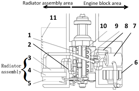
Figure 1The layout of the typical engine compartment. 1 – intake manifold, 2 – intake baffle, 3 – intercooler, 4 – radiator, 5 – fan, 6 – right outlet, 7 – air compressor, 8 – exhaust pipe, 9 – exhaust manifold, 10 – engine body, 11 – left inlet.
In the typical cabin, the discrepant direction between the temperature gradient vector and the velocity vector of high-temperature parts, such as the intercooler and radiator, resulted in poor convective heat transfer in the radiator assembly area. In view of the above problem, this research sought to enhance heat transfer by optimally matching the air velocity and temperature gradient vectors. The matching relationship between the two vectors at the heat transfer boundary was explored according to the FSP. The heat transfer enhancement module yielded optimum speed and temperature gradient vector fields with an effective cooling air inflow direction that would improve heat transfer in the radiator assembly area.
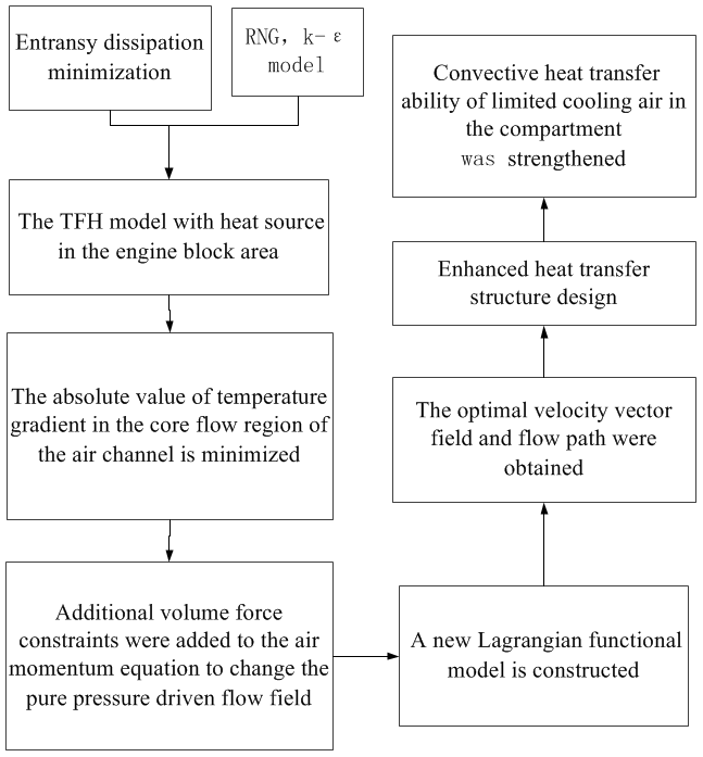
To achieve more effective cooling, this research proposes the temperature field homogenization enhanced heat transfer method in the core flow region of the engine block area, abbreviated as TFH. The TFH model helped to minimize the temperature gradient in the core flow region and to maximize it at the heat transfer boundary. Additional volume force constraints were added to the air momentum equation to change the pure pressure-driven flow field, and the optimal velocity vector field and flow path were obtained. By increasing the range of the uniform temperature field in the core flow region, the thermal boundary layer became thinner, the temperature gradient in the layer increased, and the thermal resistance decreased. A series of problems leading to high compartment temperature, such as the formation of air whirlpools, reflux, hot air retention and so on, were solved.
More comprehensive changes to the compartment structural design were made according to the multi-field coupling enhanced heat transfer principle in the engine compartment of clean-gas-bus, where FSP and TFH were both take into comprehensive consideration. The airflow field in the comprehensive structure was numerically analysed using a computational fluid dynamics (CFD) method, and the heat transfer efficiency enhanced by the improved design was verified.
The remainder of the paper is organized as follows. Section 2 introduces FSP in the radiator assembly area, studies the relationship between the matching degree of double vectors and the radiator heat transfer efficiency, and develops the FSP model. Section 3 details the TFH in the engine block area and explains the enhanced heat transfer principle of “minimum temperature gradient in the core flow region and maximum temperature gradient on the thermal boundary”. Section 4 introduces the comprehensive structure design and the simulation verification for the heat transfer efficiency enhanced by the improved design. In Sect. 5, an experimental system of the LPGB engine compartment temperature field based on infrared imaging technology is designed and developed, and the experimental results are analyzed. Finally, Sect. 6 presents the conclusions of this study.
The air velocity and the temperature gradient vector do not match at the heat transfer boundary of the radiator assembly area in a typical cabin of a rear-mounted-engine clean gas bus, which results in low heat transfer efficiency between the radiator and the high temperature of the cooling water. Based on the FSP and the theory of radiator heat dissipation, the relationship between the matching degree of the above-mentioned vectors at the heat transfer boundary, radiator heat transfer efficiency and heat dissipation performance in the compartment are analysed. Next, with the FSP model, the optimal velocity and temperature gradient for increasing heat flux in the heat boundary layer and enhancing convective heat transfer are obtained. The heat transfer efficiency of the radiator is improved, and the compartment temperature is reduced (Ou et al., 2014).
2.1 The relationship between the matching degree of double vectors and the radiator heat transfer efficiency
To improve the radiator heat transfer efficiency, it is not sufficient to just increase the airflow rate at the heat transfer boundary. It is also necessary to find a new method for heat transfer enhancement in the compartment. The heat dissipation model at the radiator is shown in the following Eq. (1).
When the automobile working conditions are constant, the heat dissipation capacity Q at the radiator can be regarded as a fixed value. cpa represents the specific heat capacity of the air with constant pressure. ma is the air mass flow, which depends on the airflow on the windward side of the radiator, εa is the heat transfer efficiency of the radiator, which is determined by the heat transfer characteristics of the cold side and the hot side of the radiator pipeline, and represents the difference between the inlet water temperature and the average air temperature on the windward side of the radiator. For the fixed-heat flow-problem of the radiator, when Q and are fixed, a higher the average air velocity on the radiator windward surface and a higher matching degree of the air velocity vector and temperature gradient vector at the heat transfer boundary of radiator result in a smaller inlet water temperature and a higher radiator efficiency.
2.2 FSP model
The energy equation expresses the coupling relationship between the cooling air velocity field and the temperature field. The general expression of the three-dimensional and unsteady convective heat transfer energy equation is as follows:
Taking the two-dimensional, steady-state, laminar boundary layer/channel flow as an example, the energy equation in the rectangular coordinate system is as follows:
where ρ represents the fluid density, cp is the constant pressure specific heat capacity, u, v, w are velocity components in the rectangular coordinates, T represents temperature, and λ is the thermal conductivity.
By comparing the convection term in Eq. (3) to the heat source term, the convection heat transfer problem is transformed into a heat conduction problem with a heat source term, which is the function of the fluid velocity. The wall heat flux, which is concerned by the research of heat transfer enhancement, can be obtained by integrating the two sides of Eq. (3) over the temperature boundary layer δt (Tao et al., 2002).
For the two-dimensional boundary layer problem, δt is the thickness of the thermal boundary layer and qw(x) is the wall heat flux at x. Equation (4) shows that the larger the sum of the convective source terms, the higher the heat flux and the convective heat transfer intensity on the wall.
For the two-dimensional thermal boundary problem, the dimensionless analysis of Eq. (4) is carried out by using Eq. (5) as follows:
where Um is the average air velocity on the windward side of the radiator or intercooler, Tm is the average air temperature on the windward side of radiator or intercooler, and ν represents the flow kinematic viscosity.
The dimensionless treatment of Eq. (4) produces Eq. (6), where an expression of the Nusselt number is obtained. The Nusselt number is proportional to the convective heat transfer intensity.
In Eq. (6), Nu, Re, and Pr represent the Nusselt number, Reynolds number, and Prandtl number, respectively.
The above analysis and conclusions are also applicable to the three-dimensional, steady-state, convective heat transfer problems with internal heat sources, which are more general.
The angle between the air velocity vector and the temperature gradient vector at the heat transfer boundary of the radiator and intercooler, which is called β, is shown in Fig. 2.

According to Eq. (6), there are three ways to enhance the convective heat transfer at the heat transfer boundary of the radiator and the intercooler:
-
Increase the Reynolds number by increasing the air velocity on the windward side of the radiator, or reducing the leakage between the inlet grid, the intercooler, and the radiator, helps to enhance the convective heat transfer.
-
Increase the Prandtl number by increasing the specific heat capacity or viscosity of the cooling fluid in the compartment.
-
Increase the dimensionless integral value .
As mentioned above, under the common working conditions of a LPGB rear-mounted engine compartment, increasing the upwind velocity of the intercooler and radiator comes at the cost of increasing the fan energy consumption, which has little significance for improving the overall heat dissipation performance of the compartment. The leakage between the inlet grille, the intercooler, and the radiator can be reduced appropriately by improving the structure of the compartment. Additionally, the cooling fluid in the compartment is air, whose heat capacity and viscosity cannot be changed. Therefore, when the Reynolds number and Prandtl number are fixed, the intensity of the convective heat transfer at the heat transfer boundary of the radiator assembly depends entirely on the vector product of the dimensionless air velocity and temperature gradient.
As seen in Eq. (7), when the values of the velocity vector and temperature gradient vector are fixed, the smaller the angle β at the heat transfer boundary is, the larger the Nusselt number. Therefore, in order to enhance convective heat transfer, the angle between the two vectors of cooling air should be reduced as much as possible, which is the guidance of the FSP (Guo et al., 2005).
TFH in the core flow region of the engine block area takes into account the coupling of multiple physical fields in the compartment and serves to overcome the problem of high cabin temperature caused by the current compartment design, which undermines heat dissipation due to limited cooling air in the cabin.
3.1 TFH
Based on the thermoelectric analogy, Guo et al. (2007) introduced a physical quantity called entransy, which is half of the product of heat capacity and temperature.
In Eq. (8), Qvh is the heat capacity for a constant volume, and T is the temperature of the object. Air entransy is related to its ability to transfer heat. This ability, namely, the entransy dissipation, can indicate the irreversible losses of the heat transfer process.
For the steady-state fluid convective heat transfer process without an internal heat source, the energy equation can be expressed in vector form.
Multiplying T on both sides of Eq. (9) yields
Equation (10) can then be transformed into
In Eq. (11), ρcpU∇(T2∕2) represents the heat transport caused by the movement of air micro-clusters in the process of convective heat transfer, ∇(λT∇T) represents the diffusion of entransy in the air, and −λ|∇T|2 is the entransy dissipation. In the equilibrium equation of entransy, the change of entransy is equal to the sum of entransy flow and entransy dissipation (Zhao et al., 2019; Chen et al., 2019).
From the expression of entransy dissipation in the core flow region of the passages in the compartment, it is found that in order to enhance convective heat transfer the entransy dissipation of air in the core flow region must be small. A smaller value of entransy dissipation corresponds to a lower modulus of the temperature gradient; thus, the more uniform the air temperature field in the core flow region of the passages is, the smaller the thermal resistance. The above rule agrees with the evaluation criterion of heat transfer intensity based on the uniformity of the temperature.
Based on the MPED, convective heat transfer is accompanied by irreversible dissipation of entransy. The direction of minimum entransy dissipation is the optimal direction of heat transfer. The heat dissipation in the rear-mounted engine compartment of the clean gas bus is poor, so it is necessary to strengthen the convective heat transfer ability of the limited cooling air in the cabin. For an engine compartment with multiple heat sources, a complex passage structure, multiple inlets and outlets, and driving air resistance affected less by cabin structure, TFH is proposed. In this method, the Lagrangian functional variation method is used to construct the temperature field homogenization model in the engine block area, and the minimum temperature gradient in the core flow region of the air passages in this area is taken as the optimization objective. Additional volume force constraints are added to the air momentum equation, with the purpose of changing the pure pressure driving flow field and obtaining the optimum vector field and flow path for enhancing heat transfer in the cabin. The idea of TFH is shown in Fig. 3.
For the LPGB studied in this paper, as it works mostly at low speed and heavy load conditions, the change of the structure in the rear-mounted engine compartment has little effect on the driving air resistance. The TFH enhancement model without flow resistance constraints can be obtained. Moreover, the thermal resistance of the convective heat transfer in the compartment is mainly located in the laminar bottom layer of the high temperature components in order to reduce the thermal resistance in this layer; thus, the temperature uniformity area in the core flow region can be increased as much as possible. As a result, the thickness of the thermal boundary layer can be thinned, and the temperature gradient of the layer can be increased to accelerate the heat conduction, with the final purpose of enhancing convective heat transfer in the cabin.
In the engine block area, it is insufficient to enhance the convective heat transfer at the heat transfer boundary. Rather, it is necessary to optimize the air velocity field and flow path in the cabin at the same time. As a result, high-temperature air can be discharged out of the compartment in the shortest possible path. Based on the TFH, the absolute value of the temperature gradient in the core flow region of the air channels in the engine block area is minimized. Coupled with the continuity equation and the energy conservation equation, a new Lagrangian functional model is constructed to obtain the TFH heat dissipation enhancement model in the core flow region.
Calculate the temperature variation for Eq. (12) and make it zero:
Calculate the velocity variation for Eq. (12) and make it zero:
Under the given boundary conditions,
The optimal velocity field for air convective heat transfer can be obtained when the temperature gradient in the core flow region of air passages is minimized.
Comparing Eq. (14) with the momentum conservation equation gives
Then, the momentum equation becomes
The boundary condition Eq. (15) for the fixed wall temperature problem can also be written as:
Therefore, Eq. (17), where the additional volume force F is added, is coupled with the continuity equation and the energy conservation equation. Scalar B is determined by the constraint Eq. (13) and the boundary condition Eq. (15). The optimal velocity field corresponding to heat dissipation enhancement through TFH in the core flow region can be obtained.
3.2 Minimum temperature gradient in the core flow region and maximum temperature gradient on the thermal boundary
According to the theory of boundary layer, when the viscous cooling air in the passage flows over the wall of a high-temperature component, a boundary layer is generated. Similar to the boundary layer, a thermal boundary layer is generated under heat exchange between air in the cabin and the wall of high-temperature components. Figure 4 shows the distribution of internal flow temperature under fixed wall temperature and fixed heat flux conditions, in which δt denotes thickness of the thermal boundary layer, T stands for temperature, R and r represent the radial sizes of the passage (Cebeci, 2005).
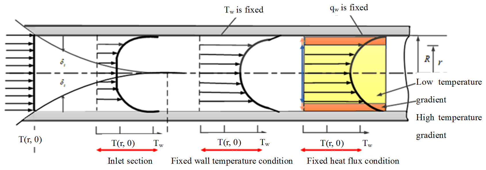
Figure 4Distribution of internal flow temperature under fixed wall temperature and heat flux conditions.
Heat transfer in the engine compartment involves both heat conduction in the laminar bottom layer and convective heat transfer in the core flow region of the passages. Thermal resistance of air in the cabin comprises the resistance of the core flow, the transition layer and the laminar bottom layer, among which the thermal resistance of the laminar bottom layer is the largest. Hence, to enhance the convective heat transfer between high-temperature components and the air, measures should be taken to reduce the thermal resistance of the laminar bottom layer. These measures include promoting homogenization of the temperature field in the core flow region and enlarging the uniform-temperature region, both of which contribute to make thinner the thermal boundary layer and increase its temperature gradient, thus strengthening heat conduction of the laminar bottom layer to enhance heat transfer. On the basis of the TFH, the enhanced heat transfer principle of minimum temperature gradient in core flow region of air passages and maximum temperature gradient on thermal boundary is proposed.
4.1 Comprehensive structure design
Guided by the principle of multi-field coupling heat transfer enhancement in the engine compartment, the unreasonable factors of the flow field in a typical structure are analysed. According to the improvements for a typical cabin structure, including the azimuth of the radiator assembly, the position of the air inlets and outlets, and the improvements to the roof structure, a new comprehensive structure is proposed.
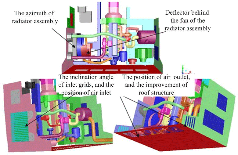
To shorten the distance between the air inlet and the radiator assembly and improve the environment around the radiator assembly, an improved radiator assembly azimuth structure is proposed based on FSP. To avoid leakage and ensure that all the cooling air entering the cabin from the left inlet can flow through the intercooler and radiator, in the comprehensive structural design shown in Fig. 5, the radiator assembly is turned counter-clockwise by 90∘, and the left air inlet and radiator assembly are designed as a whole. Compared with the typical structure (Fig. 1), in the comprehensive structure, the inlet baffle is removed. These changes aim at enhancing the convective heat transfer at the heat transfer boundary of the radiator assembly and increasing the airflow rate to the engine block area.
According to TFH, while enhancing the convective heat transfer at the heat transfer boundary, it is necessary to optimize the air velocity vector field and flow path to ensure that the hot air is delivered out of the cabin in the shortest possible path to maintain a low average temperature and uniform temperature field in the core flow region of the air channels. Based on the radiator assembly azimuth structure, the relative positions among the air inlet, radiator assembly, and the engine body are studied. As long as the air passages around the intake manifold and engine body are dredged, the high-speed airflow discharged from the fan blows towards the high-temperature components in a shorter path, and the exhaust manifold, exhaust pipe and exhaust gas turbocharger at the rear of the engine can be effectively cooled.
Considering the spatial restrictions from the passenger compartment, in order to avoid the formation of hot air vortices in the cabin roof and to make full use of the characteristic of hot air rising and cold air sinking, a roof outlet is set on the top of the engine compartment.
Moreover, in view of the low air velocity near the exhaust manifold of the engine, which is not conducive to enhancing the convective heat transfer, the comprehensive engine compartment adds a deflector behind the fan of the radiator assembly, guiding part of the high-speed airflow to the exhaust manifold to improve the air velocity in this area and strengthen the heat transfer.
4.2 Simulation analysis of air flow path and velocity field
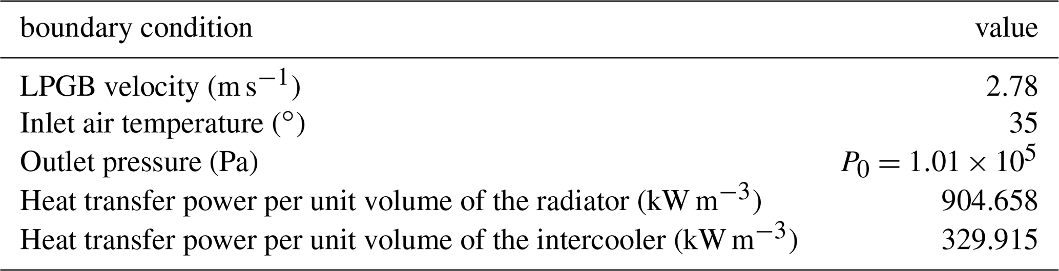
After establishing the geometric models of the LPGB body, the engine compartment and its internal components, the flow field in the calculation domain is divided into the external flow field of the body and the internal flow field of the engine compartment delineated by the boundary of the engine compartment. The internal and external flow field grids of the cabin are divided. As the LPGB works at low speed and high torque conditions most of the time, it is assumed that the bus runs in a straight line without crosswind. According to the technical parameters of the LPGB, the flow boundary conditions for simulating external flow fields and the heat source boundary for the radiator and intercooler are presented in Table 1.
Table 1The boundary conditions of an LPGB's internal and external flow fields.
The Fluent CFD solver for the engine compartment of LPGB is set as follows: pressure-based coupled implicit solver; SIMPLE solution method; precision of numerical residuals: energy equation, , other equations, ; RNG k-ε turbulence model; and non-equilibrium wall function.
Figure 6 shows the typical structure of an LPGB engine compartment and its key plane location.
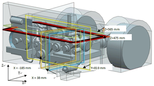
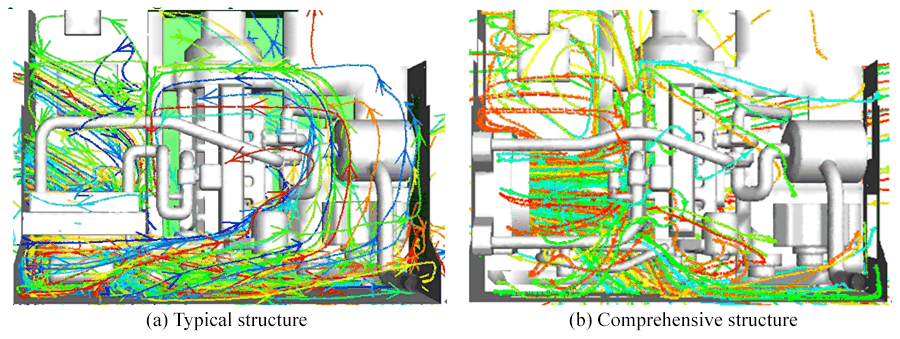
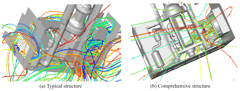
Figure 7 shows the air trajectory of the engine compartment for a typical structure and a comprehensive structure. As shown in the figure, cooling air enters the typical cabin under fan suction, flows through heat sources such as the intercooler and radiator, and then flows out at high speed from the rear of the fan. However, obstruction of the rear door of the engine compartment causes air retention behind the radiator assembly area, forming a high-temperature swirl. Part of the airflow passes through the baffle of the intake compartment to reach the engine block area, resulting in a decreased flow rate. A long counter-clockwise cooling path is formed in the engine block area, with the air heated by high-temperature components such as the exhaust manifold and exhaust gas turbocharger repeatedly. Low-speed high-temperature airflow is not conducive to heat transferring from the engine block area in the shortest possible path. The left air discharging directly from the outlets of the rear and right hatches and the high-temperature components of the engine compartment are not effectively cooled.
In the comprehensive structure, part of the high-speed air discharging from the fan is blocked by the left part of the engine body and directly flows out from the bottom of the cabin. The other part of the air passes through the passage between the intake manifold to reach the exhaust manifold, which helps to directly cool high-temperature components, such as the exhaust manifold and the exhaust turbocharger, and then passes through the grille on the right hatch door in the shortest possible path. The rest of the air is diverted to the bottom of the cabin due to the blocking effect of the rear hatch. Compared with the typical structure, there is no air whirlpool in the radiator assembly area of the comprehensive structure, and the cooling air entering the cabin flows to the front of the intake manifold with higher speed and a shorter path. The counter-clockwise low-speed whirlpool around the engine body also disappears, and the air bringing heat from the intake and exhaust manifolds is discharged from the right door grille in a shorter path.
Figure 8 is the air trajectory chart from an upward view of a typical structure and a comprehensive structure. As shown in the figure, the flow of cooling air at the bottom of the comprehensive structure is smoother.
Figure 9 shows the velocity field of the cabin in the plane Z=475 mm of a typical structure and a comprehensive structure. As shown in Fig. 9a, there is an air swirl behind the radiator assembly in the typical structure. The air velocity near the intake and exhaust manifolds of the engine is less than 3 m s−1, and there are three obvious swirls on the right side of the exhaust manifold. As shown in Fig. 9b, in the comprehensive structure, the whirlpool behind the radiator assembly disappears, and the flow velocity near the radiator assembly increases to more than 10 m s−1. The air velocity of the intake manifold also increases from less than 3 to more than 7.5 m s−1, the two whirlpools near the exhaust manifold of the engine disappear, and the air velocity vector and temperature gradient vector near the exhaust manifold match. The heat dissipation performance in the engine block area is improved.
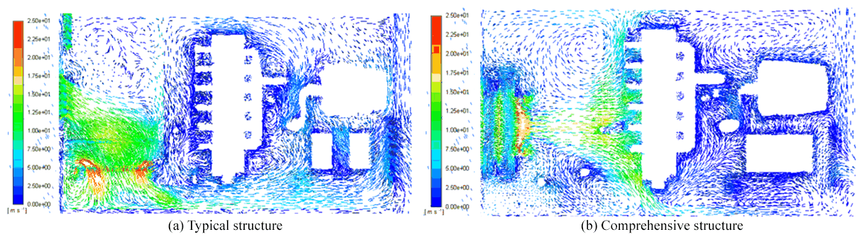
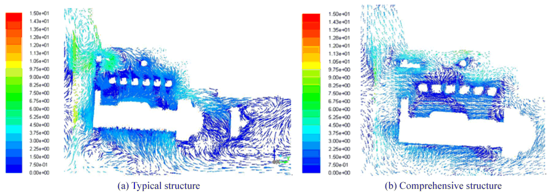
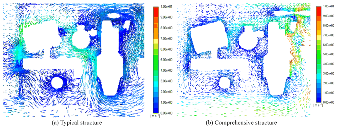
Figure 10 shows the velocity field of the cabin in the plane X=148 mm of a typical structure and a comprehensive structure. As shown in the figure, the airflow in the cabin roof of the comprehensive structure is smoother and faster, and the direction of the airflow near the exhaust manifold agrees with the FSP model.
Figure 11 is the velocity field of the plane Y=810 mm of a typical structure and a comprehensive structure. In this plane, the air velocity in zone I of the cabin roof increases from less than 2 m s−1 in the typical structure to 4.5 m s−1 in the comprehensive structure, and the air velocity in zone II increases from less than 2 m s−1 in the typical structure to 12 m s−1 in the comprehensive structure. The air velocity vectors in the two zones of the comprehensive structure conform to the FSP model.
4.3 Simulation analysis of heat dissipation performance
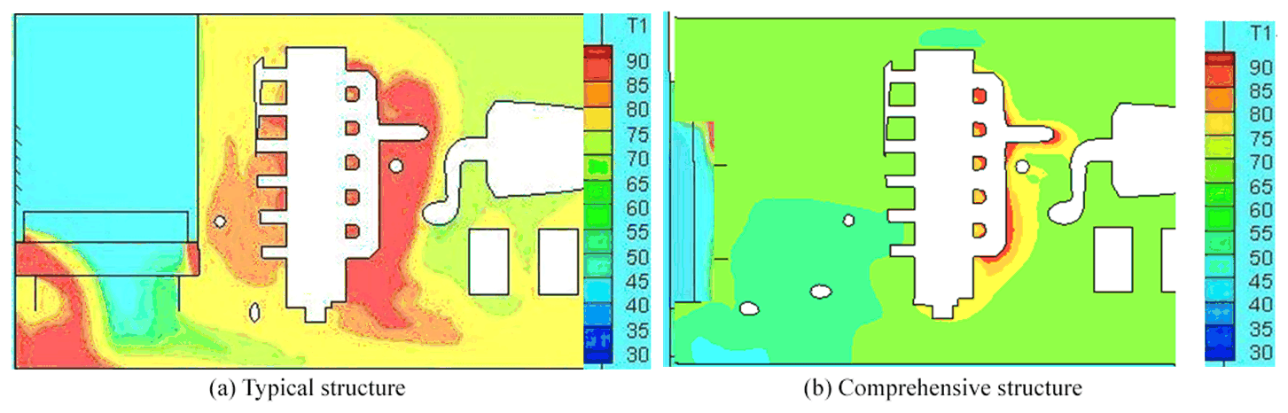
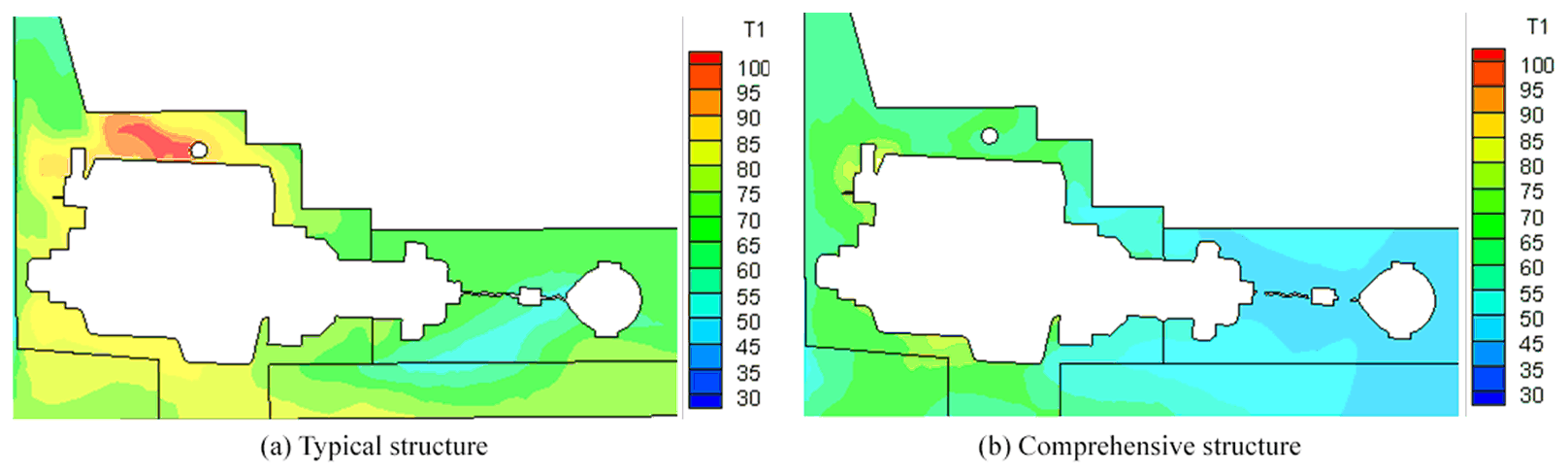
Figure 12 shows the temperature field of the plane Z=475 mm of a typical structure and a comprehensive structure. As shown in the figure, a large high-temperature zone is formed near the intake and exhaust manifolds of the typical structure, which is not conducive to improving the intake efficiency but increases the deflagration tendency of the engine. Figure 12 also reflects the temperature gradient in the core flow region of the passages in the engine block area. Obviously, the temperature gradient in the comprehensive structure is more in line with the principle of “minimum temperature gradient in the core flow region and maximum temperature gradient on the thermal boundary” in TFH. The average temperature and the temperature gradient in the core flow region are lower, which is more conducive to enhancing the convective heat transfer at the thermal boundary of the high-temperature components of the engine. At the same time, the heat is taken out of the cabin in the shortest path, and the heat dissipation performance of the engine cabin is obviously improved in the comprehensive structure.


Figure 16Infrared imaging temperature field map of high-temperature components in typical and comprehensive structure from the +Y direction under the 600 r min−1 steady-state condition.
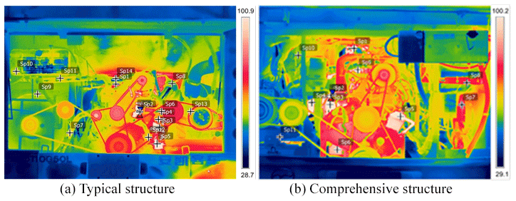
Figure 17Infrared imaging temperature field map of high-temperature components in typical and comprehensive structure from the +Y direction under the 2000 r min−1 steady-state condition.
Figure 13 shows the temperature field of the plane X=38 mm of a typical structure and a comprehensive structure. In the typical structure, the hot air in the cabin roof is retained due to the existence of an air vortex on the stepped cabin roof, and a high-temperature area of 95 ∘C on the top of the cylinder head exists. The temperature near the cylinder head of the engine in the comprehensive structure has been reduced to approximately 57 ∘C by a large margin.
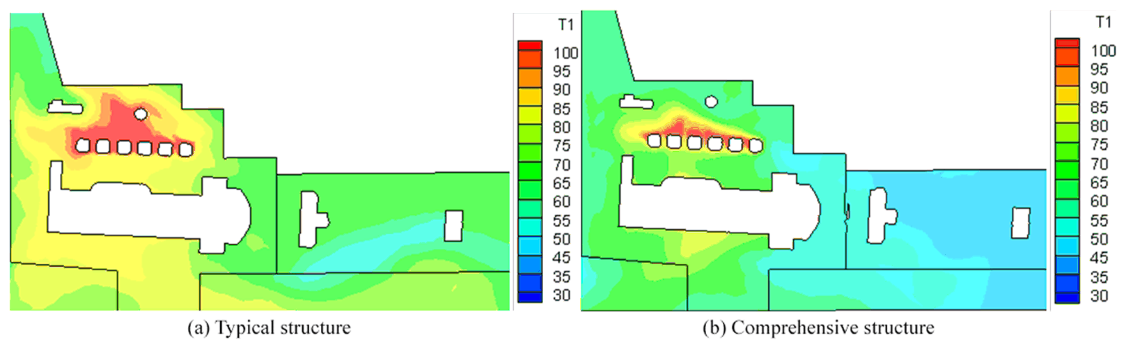
Figure 14 shows the temperature field in the plane X=148 mm of a typical structure and a comprehensive structure. As shown in the figure, compared with the typical structure, the area of the high-temperature zone near the exhaust manifold in the comprehensive structure decreases substantially.
4.4 Simulation analysis of enhanced heat transfer parameters
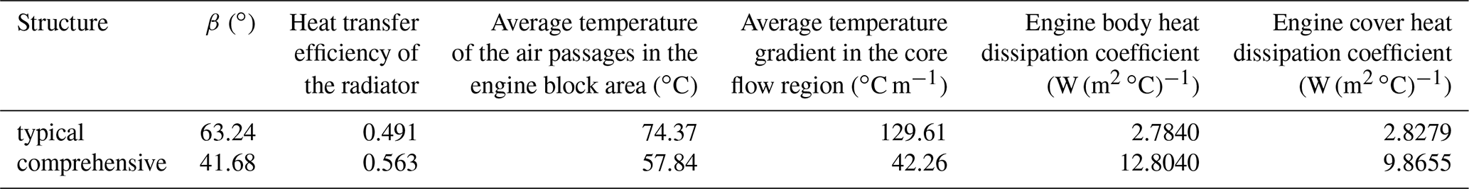
Table 2 details the average value of the air velocity-temperature gradient angle β of the radiator, the heat transfer efficiency of the radiator, the average temperature of the air passages in the engine block area, the average temperature gradient in the core flow region, and the heat dissipation coefficient of the engine body and engine cover. It can be seen that, compared with the typical structure, the β of the radiator for the comprehensive structure is decreased by 34.09 %, the heat transfer efficiency of the radiator increased by 14.66 %, the average temperature of the air passages in the engine block area decreased by 22.23 %, the average temperature gradient of the core flow region decreased by 67.39 %, and the heat dissipation coefficient of the engine body and engine cover increased by 4.60 times and 3.49 times, respectively.
Table 2Comparison of enhanced heat transfer parameters in the radiator assembly area and engine block area.
In order to verify the guiding significance of the multi-field coupling enhanced heat transfer principle for engine compartment structure design, an experimental system of the LPGB engine compartment temperature field based on infrared imaging technology was designed and developed, and the experimental results were analyzed and compared with the simulation results in Sect. 4.3.
In order to obtain the sequence of continuous infrared imaging temperature field maps and analyze the poor performance of heat dissipation in the cabin, the engine is set at various steady-state conditions of 600, 1000, 1400, 1800 and 2000 r min−1 (GBT12542-2009, 2004). When the water temperature of the engine is stable, the rear cabin door of the engine is opened, and the infrared imaging continuous temperature field maps of the typical and comprehensive structures are obtained by the infrared imager (FLIR T640) from the +Y direction (looking forward from the rear of the car). To cooperate with the normal operation of LPGB and the experimental site (Fig. 15), the ambient temperature in Guangzhou of the two experiments are 18–20 ∘C in autumn, which is far from the worst working conditions of 39–40 ∘C in summer. However, it can be predicted that, if the experimental data obtained under cool conditions can reflect the difference of heat dissipation characteristics before and after structural improvement of the engine compartment, the difference will be more obvious in hot, low-speed and high-torque adverse conditions.
Under the 600 and 2000 r min−1 steady-state conditions, the infrared imaging temperature field map of high-temperature components in typical structure (a) and comprehensive structure (b) are shown in Figs. 16 and 17, respectively. In particular, as shown in Fig. 16b, considering the actual need of assembly layout, the fan in the comprehensive structure is arranged at the right air inlet, and the intake and exhaust manifolds of the engine are respectively located at the right and left sides of the engine. The layout of other components is symmetrical with the simulation analysis model in Sect. 4.1, which can also verify the the correctness of the simulation model.
From the comparison of temperature field maps before and after the improvement of the engine compartment under the above-mentioned conditions, it can be seen that the temperature in the typical structure was higher, especially in radiator assembly area and engine block area. Moreover, the temperature gradient of the heat transfer boundary of the high-temperature components was too small, which was not conducive to the enhanced heat transfer between the high-temperature components and the surrounding cooling air, affecting the heat transfer efficiency in the cabin.
In comprehensive structure, the average temperature and the temperature gradient in the core flow region of air passages were lower, which was more conducive to enhancing the convective heat transfer at the thermal boundary. The heat was taken out of the cabin in the shortest path, and the heat dissipation performance of the engine cabin was obviously improved in this structure. The above phenomenon is consistent with the enhanced heat transfer principle of minimum temperature gradient in the core flow region and maximum temperature gradient on the thermal boundary in the TFH. The experimental results are also consistent with the simulation results in Sect. 4.3.
Based on the FSP, the optimal matching of velocity and temperature gradients for increasing heat flux in the heat boundary layer is obtained in the radiator assembly area. The convective heat transfer of the radiator assembly is enhanced, the heat transfer efficiency of the radiator improves, and the compartment temperature is reduced.
The TFH model helps to obtain the optimum vector field and flow path in the engine block area for enhancing the heat transfer. As a result, the high-temperature air can be discharged out of the compartment in the shortest possible path. According to TFH, the principle of “minimum temperature gradient in the core flow region and maximum temperature gradient on the thermal boundary” is proposed, which minimizes the temperature gradient in the core flow region and maximizes the temperature gradient on the thermal boundary, in order to reduce the laminar bottom layer thermal resistance of the high temperature components and enhance the convective heat transfer in the cabin.
A comparison of the simulation results for various structural schemes shows that the comprehensive structure based on the multi-field coupling-enhanced heat transfer principle, where FSP and TFH are both taken into comprehensive consideration, can effectively improve the heat transfer efficiency of the radiator, increase the heat dissipation coefficient of the high-temperature components, and effectively control the cabin temperature. In the comprehensive structure, the heat transfer efficiency of the radiator is increased by 14.66 %, the average temperature of the air passages in the engine block area decreased by 22.23 %, and the heat dissipation coefficient of the engine body and engine cover increased by 4.60 times and 3.49 times, respectively.
An experimental system of the LPGB engine compartment temperature field based on infrared imaging technology was designed and developed, and the experimental results were analyzed. It is found that compared with the typical structure, the engine compartment with the enhanced heat transfer structure has the following characteristic of “minimum temperature gradient in core flow region and maximum temperature gradient on thermal boundary”, which conforms to the TFH optimization model.
All the data used in this paper can be obtained from the corresponding author on request.
JO made substantial contributions to the conception and design, the theoretical analysis, the establishment of the simulation model, the acquisition of simulation and experimental data, the data analysis. JO also wrote the paper. LL supervised and structured the process of the paper.
The authors declare that they have no conflict of interest.
The authors disclosed receipt of the following financial support for the research, authorship, and publication of this article. This project is supported by National Natural Science Foundation of China (grant no. 51605104) and the Foundation of Science and technology project of Guangdong Province (2015A010106016). Project leader, Jiajie Ou.
This research has been supported by the National Natural Science Foundation of China (grant no. 51605104) and the Science and technology project of Guangdong Province (grant no. 2015A010106016).
This paper was edited by Kheng Lim Goh and reviewed by two anonymous referees.
Ahmadi, P., Hajabdollahi, H., and Dincer, I.: Cost and entropy generation minimization of a cross-flow plate fin heat exchanger using multi-objective genetic algorithm, J. Heat Transf., 133, 312–318, https://doi.org/10.1115/1.4002599, 2011.
Baskar, S. and Rajaraman, R.: Thermal Management of Automotive Heat Exchanger Under Obstructed Cooling Airflow Path: A Case Study, IJST T. Mech. Eng., 2018, 1–12, https://doi.org/10.1007/s40997-018-0216-3, 2018.
Bejan, A.: Entropy generation minimization: the new thermodynamics of finite-size devices and finite-time processes, J. Appl. Phys., 79, 1191, https://doi.org/10.1063/1.362674, 1996.
Cebeci, T., Shao, J. P., and Kafyeke, F.: Computational fluid dynamics for engineers: from panel to Navier-Stokes methods with computer programs, Engineering Education System, 41, 603–605, https://doi.org/10.1007/3-540-27717-X, 2005.
Chen, X., Zhao, T., and Zhang, M. Q.: Entropy and entransy in convective heat transfer optimization: A review and perspective, Int. J. Heat Mass Tran., 137, 1191–1220, https://doi.org/10.1016/j.ijheatmasstransfer.2019.04.017, 2019.
Cheng, X. T., Zhang, Q. Z., and Liang, X. G.: Analyses of entransy dissipation, entropy generation and entransy-dissipation-based thermal resistance on heat exchanger optimization, Appl. Therm. Eng., 38, 31–39, https://doi.org/10.1016/j.applthermaleng.2012.01.017, 2012.
Guo, J. F., Xu, M. T., and Cheng, L.: Principle of equipartition of entransy dissipation for heat exchanger design, Sci. China Technol. Sc., 05, 155–160, 2010.
Guo, Z. Y.: Physical mechanism of convective heat transfer: synergy of velocity field and heat flow field, Chinese Sci. Bull., 2000, 2118–2122, 2000.
Guo, Z. Y., Tao, W. Q., and Shah, R. K.: The field synergy (coordination) principle and its applications in enhancing single phase convective heat transfer, Int. J. Heat Mass Tran., 48, 1797–1807, https://doi.org/10.1016/j.ijheatmasstransfer.2004.11.007, 2005.
Guo, Z. Y., Zhu, H. Y., and Liang, X. G.: Entransy – a physical quantity describing heat transfer ability, Int. J. Heat Mass Tran., 50, 2545–2556, https://doi.org/10.1016/j.ijheatmasstransfer.2006.11.034, 2007.
Harambat, F.: Energy Management in Car Underhood Compartment – Temperature and Heat Flux Analysis of Car Inclination Effects, Heat Transfer Eng., 36, 68–80, https://doi.org/10.1080/01457632.2014.906283, 2014.
Juan, T.: Investigation and Assessment of Factors Affecting the Underhood Cooling Air Flow Using CFD, Proceedings of the 2008 SAE World Congress and Exhibition, Rosemont, IL, USA, SAE International, https://doi.org/10.4271/2008-01-2658, 2008.
Kaleli, A., Kaltakkiran, G., Dumlu, A., and Ayten, K. K.: Design and control of intelligent cooling system for IC engine, Proceedings of 2017 International Conference on Engineering and Technology, 2017 International Conference on Engineering and Technology, 21–23 August 2017, IEEE, Institute of Electrical and Electronics Engineers Inc. https://doi.org/10.1109/ICEngTechnol.2017.8308163, 2018.
Kang, Y. H., Wang, Q. H., and Lu, X. F.: Experimental and theoretical study on the flow, mixing, and combustion characteristics of dimethylether, methane, and LPG jet diffusion flames, Fuel Process. Technol., 129, 98–112, https://doi.org/10.1016/j.fuproc.2014.09.004, 2015.
Khaled, M., Harambat, F., Yammine, A., and Peerhossaini, H.: Active Control of Air Flow in Vehicle Underhood Compartment: Temperature and Heat Flux Analysis, Proceedings of the ASME 2010 3rd Joint US-European Fluids Engineering Summer Meeting, FEDSM 2010 Collocated with 8th International Conference on Nanochannels, Microchannels, and Minichannels, Montreal, QC, Canada, SAE International, https://doi.org/10.1115/FEDSM-ICNMM2010-30322, 2010.
Khaled, M., Mangi, F., Hage, H. E., Harambat, F., and Peerhossaini, H.: Fan air flow analysis and heat transfer enhancement of vehicle underhood cooling system–towards a new control approach for fuel consumption reduction, Appl. Energ., 91, 439–450, https://doi.org/10.1016/j.apenergy.2011.10.017, 2012.
Khaled, M., Habchi, C., Harambat, F., Elmarakbi, A., and Peerhossaini, H.: Leakage effects in car underhood aerothermal management: temperature and heat flux analysis, Heat Mass Transf., 50, 1455–1464, https://doi.org/10.1007/s00231-014-1347-8, 2014a.
Khaled, M., Ramadan, M., Hage, H. E., et al.: Review of underhood aerothermal management: Towards vehicle simplified models, Appl. Therm. Eng., 73, 842–858, https://doi.org/10.1016/j.applthermaleng.2014.08.037, 2014b.
Larsson, L., Wiklund, T., and Löfdahl, L.: Cooling performance investigation of a rear mounted cooling package for heavy vehicles, Proceedings of the 2011 SAE World Congress and Exhibition, Detroit, MI, USA, SAE International, https://doi.org/10.4271/2011-01-0174, 2011a.
Larsson, L., Löfdahl, L., Dahl, E., and Wiklund, T.: Continuing cooling performance investigation of a rear mounted cooling package for heavy vehicles, SAE 2011 Commercial Vehicle Engineering Congress, Rosemont, IL, USA, SAE International, https://doi.org/10.4271/2011-01-2285, 2011b.
Liu, S. C., Li, L. F., Zhang, Y., and Mi, C. J.: Flow Field Heat Dissipation Analysis and Structural Modification of Engine Compartment Based on Velocity-temperature Field Coupling, Automot. Eng., 39, 879–888, https://doi.org/10.19562/j.chinasae.qcgc.2017.08.005, 2017.
Lu, P., Gao, Q., and Wang, Y.: The simulation methods based on 1D/3D collaborative computing for the vehicle integrated thermal management, Appl. Therm. Eng., 104, 42–53, https://doi.org/10.1016/j.applthermaleng.2016.05.047, 2016.
Lu, P. Y., Gao, Q., Lv, L., and Xue, X. Y.: Numerical calculation method of model predictive control for integrated vehicle thermal management based on underhood coupling thermal transmission, Energies, 12, 259, https://doi.org/10.3390/en12020259, 2019.
Lukeman, Y., Lim, F. Y., Abdullah, S., Zulkifli, R., Shamsudeen, A., and Hasan, M. K.: Underhood Fluid Flow and Thermal Analysis for Passenger Vehicle, Appl. Mech. Mater., 165, 150–154, https://doi.org/10.4028/www.scientific.net/AMM.165.150, 2012.
Merati, P., Davis, C., Chen, K. H., and Johnson, J. P.: Underhood Buoyancy Driven Flow – An Experimental Study, J. Heat Transf., 133, 082502, https://doi.org/10.1115/1.4003758, 2011.
Ordóñez, J. C. and Bejan, A.: Entropy generation minimization in parallel-plates counterflow heat exchangers, Int. J. Energ. Res., 24, 843–864, https://doi.org/10.1002/1099-114X(200008)24:10<843::AID-ER620>3.0.CO;2-M, 2015.
Ou, J. J., Li, L. F., Cui, T., and Chen, Z.-M.: Application of field synergy principle to analysis of flow field in underhood of LPG bus, Comput. Fluids, 103, 186–192, https://doi.org/10.1016/j.compfluid.2014.07.029, 2014.
Pan, F. P., Schoon, R., Putta, S., Ogale, A., and Chen, C.: A practical simulation approach for truck cooling system at early stage design process and development, Proceedings of the 2010 SAE World Congress and Exhibition, USA, SAE International, https://doi.org/10.4271/2010-01-1927, 2010.
Prigogine, I.: An Introduction to the Thermodynamics of Irreversible Processes, J. Electrochem. Soc., 110, 97C, https://doi.org/10.1149/1.2425756, 1963.
Sharma, P., Parwal, M., and Ayyar, E.: Design Optimization of Engine Cooling Unit Packaging for Commercial Vehicle, SAE 2018 International Conference on Advances in Design, Materials, Manufacturing and Surface Engineering for Mobility, Chennai, India, https://doi.org/10.4271/2018-28-0013, 2018.
Shen, K., Xu, X. Y., and Wang, X. Y.: Experiment on Temperature Field in Rear Engine Compartment, Journal of Tongji University (Natural Science), 41, 779–783, https://doi.org/10.3969/j.issn.0253-374x.2013.05.024, 2013.
Singh, R. and Shen, F.: CFD-based Robust Optimization of Front-end Cooling Airflow, Proceedings of the 2007 SAE World Congress and Exhibition, Detroit, MI, USA, SAE International, https://doi.org/10.4271/2007-01-0105, 2007.
Song, W. M., Meng, J. A., and Li, Z. X.: Numerical study of air-side performance of a finned flat tube heat exchanger with crossed discrete double inclined ribs, Appl. Therm. Eng., 30, 1797–1804, https://doi.org/10.1016/j.applthermaleng.2010.04.013, 2010.
Sun, X. X., Shao, C. M., Wang, G. Z., Li, R. P., Niu, D., and Shi, J.: Global energy management for propulsion, thermal management system of a series-parallel hybrid electric vehicle, Proceedings of the 3rd International Conference on Vehicle Technology and Intelligent Transport Systems, SciTePress, available at: https://www.scitepress.org/Papers/2017/63704/63704.pdf (last access: 1 June 2020), 2017.
Tao, W. Q., Guo, Z. Y., and Wang, B. X.: Field synergy principle for enhancing convective heat transfer-its extension and numerical verifications, Int. J. Heat Mass Tran., 45, 3849–3856, https://doi.org/10.1016/S0017-9310(02)00097-2, 2002.
Vegendla, S. N. P., Sofu, T., Saha, R., Hwang, L.-K., and Madurai Kumar, M.: Investigation on Underhood Thermal Analysis of Truck Platooning, SAE International Journal of Commercial Vehicles, 11, 5–16, https://doi.org/10.4271/02-11-01-0001, 2018.
Walls, M., Joo, M., and Ross, M.: Impact of the Direct Injection of Liquid Propane on the Efficiency of a Light-Duty, Spark-Ignited Engine, SAE World Congress Experience, Detroit, MI, USA, SAE International, https://doi.org/10.4271/2017-01-0865, 2017.
Wang, H. C., Shan, X. Z., and Yang, Z. G.: Numerical simulation of the influence of ground effect simulation on vehicle cooling system experiment in climate wind tunnel, Journal of Jilin University (Engineering and Technology Edition), 47, 1373–1378, https://doi.org/10.13229/j.cnki.jdxbgxb201705007, 2017.
Wang, S. M., Jian, G. P., Wang, J. R., and Sun, L. J.: Application of entransy-dissipation-based thermal resistance for performance optimization of spiral-wound heat exchanger, Int. J. Heat Mass Tran., 116, 743–750, https://doi.org/10.1016/j.ijheatmasstransfer.2017.09.061, 2018.
Wei, D., Williams, J., Karanth, D., and Sovani, S.: CFD Application in Automotive Front-End Design, Proceedings of the 2006 SAE World Congress and Exhibition, Detroit, MI, USA, SAE International, https://doi.org/10.4271/2006-01-0337, 2006.
Wu, J. and Guo, Z. Y.: Application of entransy dissipation extremum principle in radiative heat transfer optimization, Sci. China Ser. E, 51, 1306–1314, https://doi.org/10.1007/s11431-008-0141-6, 2008.
Wu, X. H., Yuan, P., Luo, Z. M., Wang, L. X., and Lu, Y.-L.: Heat Transfer and Thermal Resistance Characteristics of Fin with Built-In Interrupted Delta Winglet Type, Heat Transf. Eng., 37, 172–182, https://doi.org/10.1080/01457632.2015.1044397, 2016.
Xia, M. X., Zhao, L. W., and Xu, H.: Overall performance factor for evaluating intensified heat conduction based on the field synergy theory, Journal of Engineering for Thermal Energy and Power, 26, 197–201+254, 2011 (in Chinese).
Yang, S. Z., Wang, D., Dang, Y., and Li, L. G.: Numerical Simulation and Optimization of the Underhood Fluid Field and Cooling Performance for Heavy Duty Commercial Vehicle under Different Driving Conditions, Proceedings of the 2015 SAE World Congress and Exhibition, Rosemont, IL, USA, SAE International, https://doi.org/10.4271/2015-01-2902, 2015.
Yu, Z. Q., Wang, P., Zhou, W. J., Li, Z. Y., and Tao, W.-Q.: Study on the consistency between field synergy principle and entransy dissipation extremum principle, Int. J. Heat Mass Tran., 116, 621–634, https://doi.org/10.1016/j.ijheatmasstransfer.2017.09.044, 2018.
Zhang, C. H., Uddin, M., and Foster, L.: Investigation of the Turbulence Modeling Effects on the CFD Predictions of Passenger Vehicle Underhood Airflow, Proceedings of the 2018 SAE World Congress and Exhibition, Detroit, MI, USA, SAE International, https://doi.org/10.4271/2018-01-0476, 2018.
Zhao, T., Liu, D., and Chen, Q.: A collaborative optimization method for heat transfer systems based on the heat current method andentransy dissipation extremum principle, Appl. Therm. Eng., 146, 635–647, https://doi.org/10.1016/j.applthermaleng.2018.10.016, 2019.
- Abstract
- Introduction
- FSP in the radiator assembly area
- TFH in the engine block area
- Comprehensive structure design and simulation verification
- Experiment verification
- Conclusion
- Data availability
- Author contributions
- Competing interests
- Acknowledgements
- Financial support
- Review statement
- References