the Creative Commons Attribution 4.0 License.
the Creative Commons Attribution 4.0 License.
 | 18 Jan 2019
Energy saving optimal design and control of electromagnetic brake on passenger car
Yanzhi Yan
Xiaoming Xu
In this paper, the optimal design and control method of electromagnetic brake for a typical city driving cycle are studied to improve its energy consumption characteristics. The prediction models of the braking performance and power consumption for electromagnetic brake were established, and their accuracies were verified on the hardware of the loop simulation platform. Moreover, the energy consumption based on the ECE-EUDC driving condition was taken as the objective function, and a mathematical model for the optimal design of the electromagnetic brake was established. Genetic Algorithm was used to seek global optimal solution of these design variables on the premise of the given electrical and space constraints. Finally, the effect of thermodynamic properties of electromagnetic brake on the energy consumption characteristics was analyzed, and the energy saving control method of electromagnetic brake was also proposed. Experimental results show that the energy saving optimal design and control that this paper investigates can significantly improve the energy efficiency of electromagnetic brake.
- Article
(4791 KB) - Full-text XML
- BibTeX
- EndNote


Despite of the high braking efficiency of friction brake, noise and harmful dust may be generated during braking. In addition, heat fading will occur under continuous braking condition. Eddy current brake is a type of non-contact brake with non-friction, simple controlling and braking smoothly (Karakoc et al., 2014). As auxiliary brake, eddy current brakes have been widely used on commercial vehicles (Pernestal et al., 2012) and high speed train (Wang and Chiueh, 1998). However, there are many restrictions on regenerative brake, such as battery charge and discharge performance, SOC, etc., so regenerative brake is not suitable for emergency braking. Using the eddy current brake to realize low intensity brake can reduce the braking time effectively when a passenger car is running on the crowded city road (Park et al., 2014). Under emergency braking condition, eddy current brake can decrease the response time of the braking system and enhance the safety performance of the passenger car (He et al., 2013).
Some researchers have been devoted to study the application of eddy current brake on passenger cars. An electromagnetic eddy current brake (electromagnetic brake) used in the passenger car was put forward by Sohel Anwar. The experimental data of braking torque and rotational speed was fitted to a formula (Anwar and Stevenson, 2006). The application of electromagnetic brake on the vehicle stability control had been further studied. The braking torque of electromagnetic brake was controlled to ensure that the passenger car would not deviate from the original path while braking (Anwar, 2005). Gay and Ehsani (2005, 2006) proposed a permanent magnet eddy current brake for passenger car. They set up a 2-D finite element models for permanent magnet eddy current brake and then studied its braking characteristic. Liu and He (2010) studied the influence law of the structure parameters of electromagnetic brake on braking torque. An optimization mathematical model which main optimization design object was increasing the braking torque was created to obtain the best structure parameters.
Electromagnetic brake needs to use the power supply of passenger car which leads to an additional fuel consumption (Jian et al., 1999). Furthermore, energy consumption can affect the usability of the electromagnetic brake. Therefore, it is a key to optimize the structure parameters of the electromagnetic brake in the design process and propose its energy saving control method. Obviously, the basis of design or control of the electromagnetic brake is to establish an accurate performance prediction model. However, materials of the brake disc and iron core are all soft magnetic materials (Venkataratnam and Kadir, 1982a, b). There are saturation nonlinearity relationships between magnetic field strength and the magnetic flux density in the brake disc and iron core. In addition, the brake temperature changes drastically during operation (Hu et al., 2018a, b, 2019). The nonlinear characteristic of the soft magnetic materials and temperature affect the accuracy of the performance prediction model.
As a result, establishing the performance prediction model will be the priority issue on the basis of considering the nonlinear characteristic of the soft magnetic materials. In the section two, the working principle and structure of the electromagnetic brake are introduced. The prediction model of braking performance and energy consumption of electromagnetic brake are developed and the accuracies of these models are verified on the test bench in the section three. In the section four, the optimization design model of electromagnetic brake is put forward. The main optimization objective is set as the total energy consumption under ECE driving condition and the optimization method is Genetic Algorithm. In the last section, the effect of thermodynamic properties of electromagnetic brake on its energy consumption characteristics is analyzed and its own energy saving control method is also proposed. Before ending this introductory section, it is worthwhile pointing out the main contributions of this paper as follows.
Magnetic and temperature are important factors affecting the performance of electromagnetic brakes, while the strong nonlinear characteristics of magnetism and temperature lead to research difficulties and no solution. Based on this, an electromagnetic brake model is established by considering the nonlinear characteristics of magnetism and temperature.
According to the analysis of the influence of magnetic nonlinearity, it is found that there is a low power consumption area existing in the electromagnetic brake. We optimize the structural parameters so that the working range is within this area as much as possible.
By analyzing the effect of thermodynamics characteristics of electromagnetic brake on its energy consumption characteristics, the energy-saving optimization design of electromagnetic brakes is deeply studied considering the change of pole pairs.
For conductor, it could cause the magnetic field lines cut relatively whether moving in a stationary magnetic field or static in a time-varying magnetic field. According to Faraday's law of electromagnetic induction, the inductive electromotive force (EMF) is obtained in the conductor. Consequently, the inductive current is produced inside the conductor. Distribution of inductive current in the conductor changes with the surface of conductor and the distribution of magnetic flux. Its path often looks like a vortex in the water. So it is commonly referred to as eddy current. Eddy current in the magnetic field causes a force opposite to its direction of motion while heat power comes from the eddy current in moving conductor. Basd on the law of conservation of energy, the heat generated by the eddy current is equal to the decrease in kinetic energy of the conductor. Kinetic energy loss resulted from the eddy current is called eddy current loss. Basic principle of eddy current brake is to use eddy current loss to convert kinetic energy of the moving conductor into heat energy to achieve the purpose of braking (Park et al., 2014).
As showed in Fig. 1, the electromagnetic brake should integrate with the friction brake taking into the restriction of the installation space of the wheel. Electromagnetic brake is consisted of exciting coil, iron core, bracket and brake disc. The current pass through the exciting coil and then the exciting coil generates an electromagnetic field during braking. Magnetic flux lines go through the iron core, the air gap and the brake disc and come back to the iron core forming a loop. Once the brake disc and the magnetic field lines move relative, eddy current is produced in the surface of the brake disc so that the brake disc speed out opposite to its direction of movement arising from braking torque.
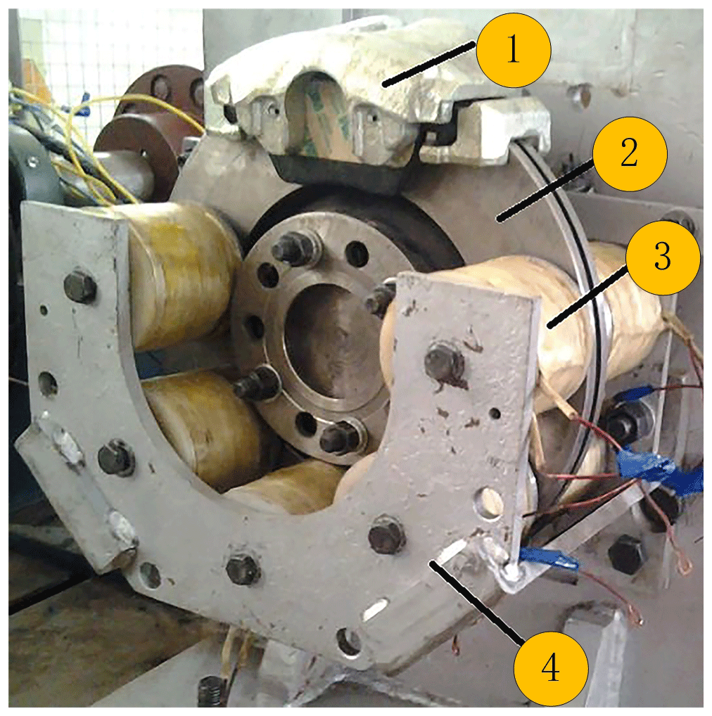
Figure 1(1) Brake caliper. (2) Brake disc. (3) Exciting coil and irone core. (4) Bracket. Principle prototype of electromagnetic brake.

3.1 Prediction model of braking performance
3.1.1 Nonlinear properties of soft magnetic material
The brake disc is made of gray cast iron mostly and the main material of iron core is industrial pure iron. Both are soft magnetic materials. The magnetic induction intensity curve with the applied magnetic field strength is saturation nonlinear as shown in Fig. 2. Saturation nonlinearity of soft magnetic materials are very important and can't simply be linearized in terms of mathematical model of electromagnetic brake predicting its braking performance.
Magnetization curves of soft magnetic materials are mostly obtained by practical measuring and saturation nonlinearity are generally expressed by piecewise linear method (Um et al., 1997, 1999). In this paper, the saturation nonlinearity will be expressed by the power series functions. The least squares method is used to determine the coefficients and obtain magnetization curves of soft magnetic materials.
Where, B1 and B2 represent magnetic flux density of iron core and brake disc, respectively. H1 and H2 represent magnetic field strength of iron core and brake disc, respectively. c1, c2, c3, c4 are fit coefficients, and their values are , , , respectively.
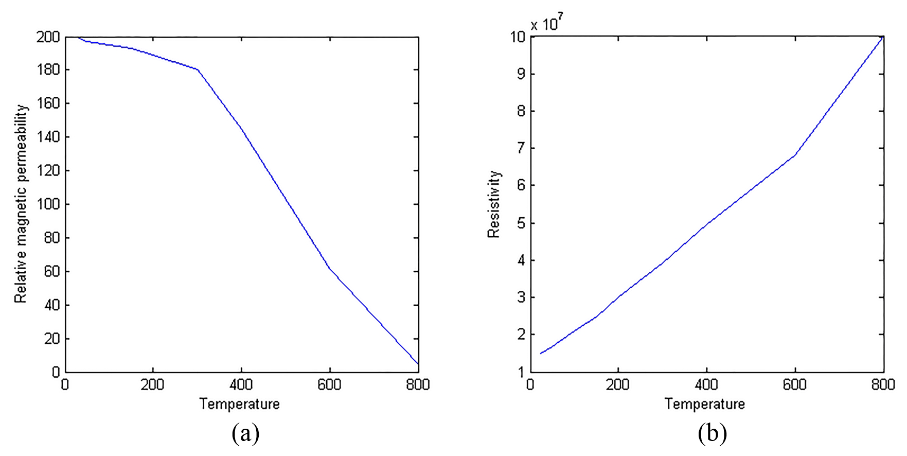
During braking, the kinetic energy of the passenger car which is taken up by the brake disc will be dissipated into heat. The excitation coil which has energized for a long time will also produce some heat. Saturation nonlinearity of resistivity and relative magnetic permeability of soft magnetic materials with the temperature needs to be investigated for predicting the torque of electromagnetic brake precisely (Zhao et al., 2018a, b; Zhao and Zhang, 2018).
As showed in Fig. 3a, piecewise linearization is employed to process the relative magnetic permeability- temperature curve. Relative magnetic permeability can be expressed in the form of
Where, μ1 and μ2 are relative magnetic permeability constant coefficients, where μ1=266 and μ2=300. a1 and a2 represent temperature coefficients of brake disc permeability. t1 is brake disc temperature, where and .
As illustrated in Fig. 3b, the linearization of the resistivity versus temperature curve should be made directly taking the strong cooling capacity of disc brake and narrow temperature range of copper wire into consideration.
Where, ρFe, ρ1 and b1 respectively represent resistivity, ambient temperature resistivity, temperature coefficient of the brake disc, where and b1=0.008. ρCu, ρ2 and b2 respectively represent resistivity, ambient temperature resistivity, temperature coefficient of the copper wire, where and b2=0.004. t0 is ambient temperature, and t0=25.
3.1.2 Virtual Coil Hypothesis
According to the eddy current theory, the action area of eddy current is seen as the closed ring with different sizes of the radius, as shown in Fig. 4. To avoid the experience factor in establishing the mathematical model, the eddy current in action area of eddy current is assumed to be equivalent to a virtual coil with the iron core. Assuming the current through virtual coil is Ie, and its number of turns is 1 (Karakoc et al., 2014). The influence of the eddy current magnetomotive force (MMFs) in the calculation of the total magnetic MMFs is considered using virtual coil hypothesis.
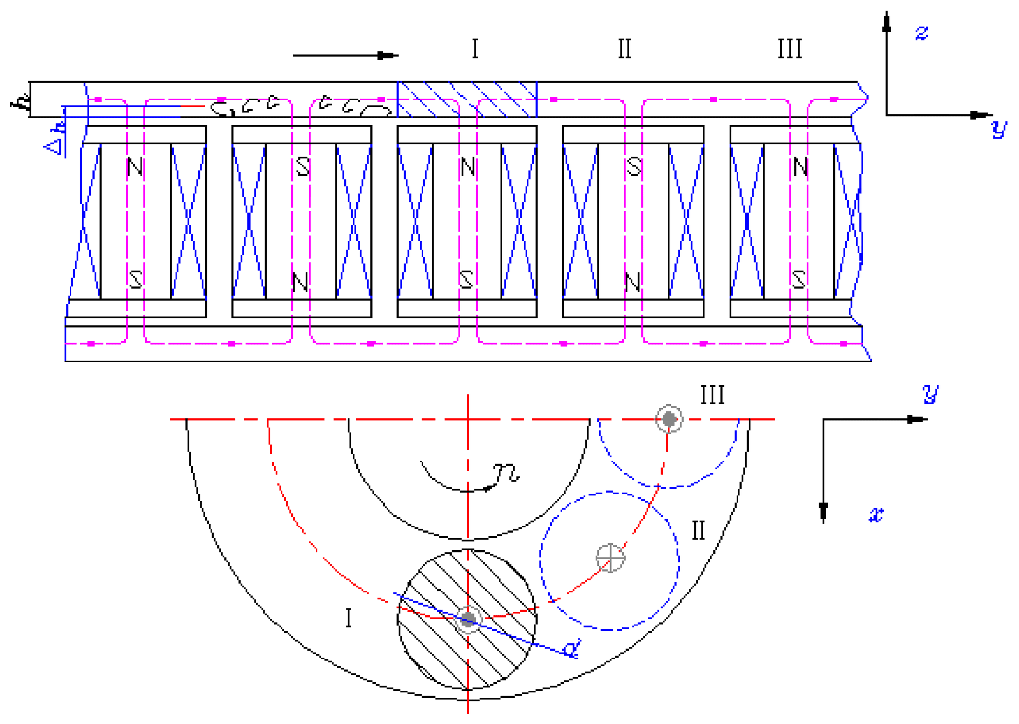
When the brake disc is rotating at a constant speed, the magnetic flux within action area of eddy current is constantly changing and this change can be regarded as the cosine law. The magnetic flux could be defined as
Where, B, Sp, ω and Np represent air gap flux density, action area of eddy current, angular velocity of the magnetic field changes and number of pole pairs of the excitation coil, respectively.
Inductive electromotive force generated by magnetic flux variations can be expressed as
Where, r is the radius of the closed ring.
The equivalent resistance of the closed ring is obtained as
Where, Δh and μ0 represent skin deep of eddy current and permeability of vacuum, respectively.
The eddy current on the closed ring can be written as
Transient current through virtual coil can be expressed in form of
Then eddy current MMFs can be written as
3.1.3 Magnetic Circuit Analysis
Eddy current MMFs and exciting MMFs are all AC excitation which makes the magnetic circuit analysis of electromagnetic brake complicated. Therefore, this prediction model is assumed as the steady-state model and the magnetic circuit is equivalent to a DC magnetic circuit. Depending on Kirchhoff's law and constraint relations of magnetic flux and magnetic pressure in paragraphs, assumption that based flux is equivalent to 85 % of leakage flux is made.
Where, H, lg, N, I, Φ, l, Φ1 and Φ2 represent air-gap magnetic field strength, gap length, coil turns, excitation current, main exciting magnetic flux, the length of the excitation coil skeleton, magnetic flux of air gap magnetic field and brake disc magnetic field, respectively.

Figure 5Hardware in the loop simulation platform of the electromagnetic and frictional integrated brake system.
Assuming exciting magnetic field, air gap magnetic field and brake discs magnetic field get the same cross-sectional area.
where, A0, A1 and A2 represent cross-sectional area of the exciting magnetic field, air gap magnetic field and brake discs magnetic field, respectively.
The air gap magnetic flux density can be expressed in form of
Where B is air-gap magnetic flux density.
According to Eq. (8), the electromagnetic brake power is calculated as (Zhang et al., 2013)
Where k is gain coefficient of active area, . d and rm represent the diameter of the iron core and the center radius of the brake disc, respectively
The prediction model of braking performance of electromagnetic brake can be obtained as
3.2 The prediction model of energy consumption
When the electromagnetic brake is working, a DC chopper serves to change the conduction time of the electromagnetic brake and power supply. The braking torque required by the controller is adjusted by changing the equivalent voltage on the exciting coil (Zhang et al., 2014). According to the Eq. (14), the exciting current of single exciting coil can be written as:
Where T is the braking torque required by the controller.
The resistance of the exciting coil is related to the diameter of the copper wire and the size of the coil skeleton, the diameter of the iron core and the electrical resistivity of copper wire. The resistance of an exciting coil can be described as:
Here a is the number of turns in radial direction, . b is number of turns in axial direction, . H, D and δ represent the width, external diameter of the skeleton and the thickness of the skeleton, respectively. d0 is the diameter of the copper wires.
The numbers of turns can be obtained as:
The quantity of exciting coil of an electromagnetic brake is 4Np. These two opposite exciting coils are cascaded as an exciting winding. Exciting windings are parallel to each other. The power consumption of electricity can be drawn up as:
3.3 Experimental study
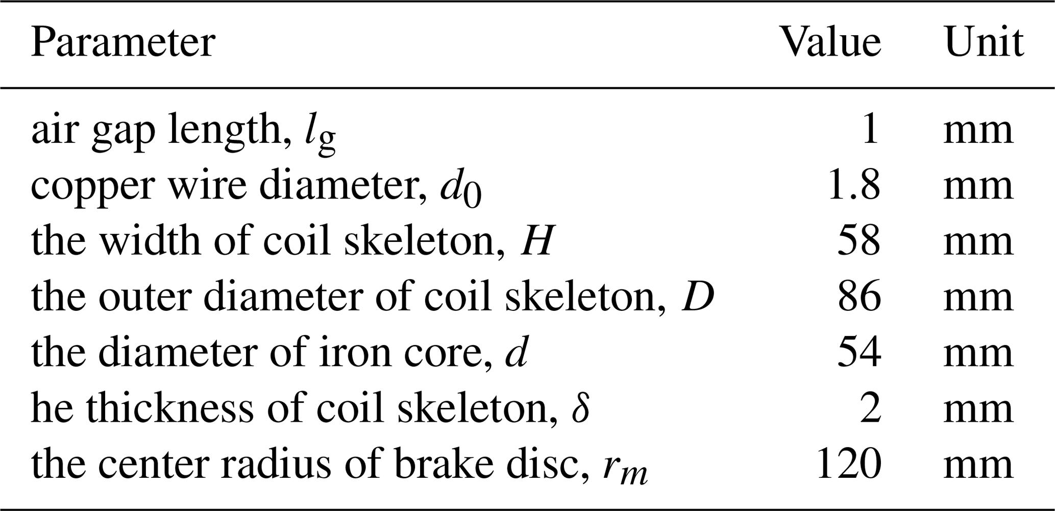
The principle prototype of electromagnetic brake which has been designed by Jiangsu Province Key Laboratory of Automotive Engineering is treated as example and the hardware in the loop simulation platform of electromagnetic and friction integration braking system is used to do experimental verification as shown in Fig. 5 (He et al., 2013). Structural parameters of electromagnetic brake is shown in Table 1. In this paper, the dichotomy is used to obtain the air-gap magnetic flux density. In order to solve the nonlinear Eq. (12), a new function is given as follow:

Braking torque of electromagnetic brake increases as the wheel speed increases if the wheel speed is less than 500 r min−1. When the wheel speed reaches 500 r min−1, braking torque peaked. And if the wheel speed continues to rise, the braking torque really starts to drop. Theoretical calculation curve can be a good approximation of the experimental curve especially in the high-speed region and also follow the downward trend of the torque-speed curve which indicates that this prediction model of braking performance is in a position to articulate the impact of eddy current MMF on air gap MMF. Meanwhile, both curves show the same critical speed reflecting this model can well express the influence of magnetic saturation characteristics of soft magnetic materials. There are differences of amplitude of the experimental curve and the theoretical curves as shown in Fig. 6 which may be caused by subtle changes of the air gap length in the process of installing electromagnetic brake.
Firstly, friction brake continues working several times so that the brake disc elevates its temperature for absorbing the braking energy sufficiently. At different temperature of the disc brake, electromagnetic brake work several times to obtain braking torque–temperature experimental curve which showed in Fig. 7a. The theoretical calculation curve of braking torque changes with temperature of the brake disc agrees well with the experimental curve. But experimental curve can only express the temperature of the brake disc between 20–250∘ due to the difficulty of the experiment operability. With increasing temperature of the brake disc, the decrease of braking torque is limited which indicates its strong fade resistance.
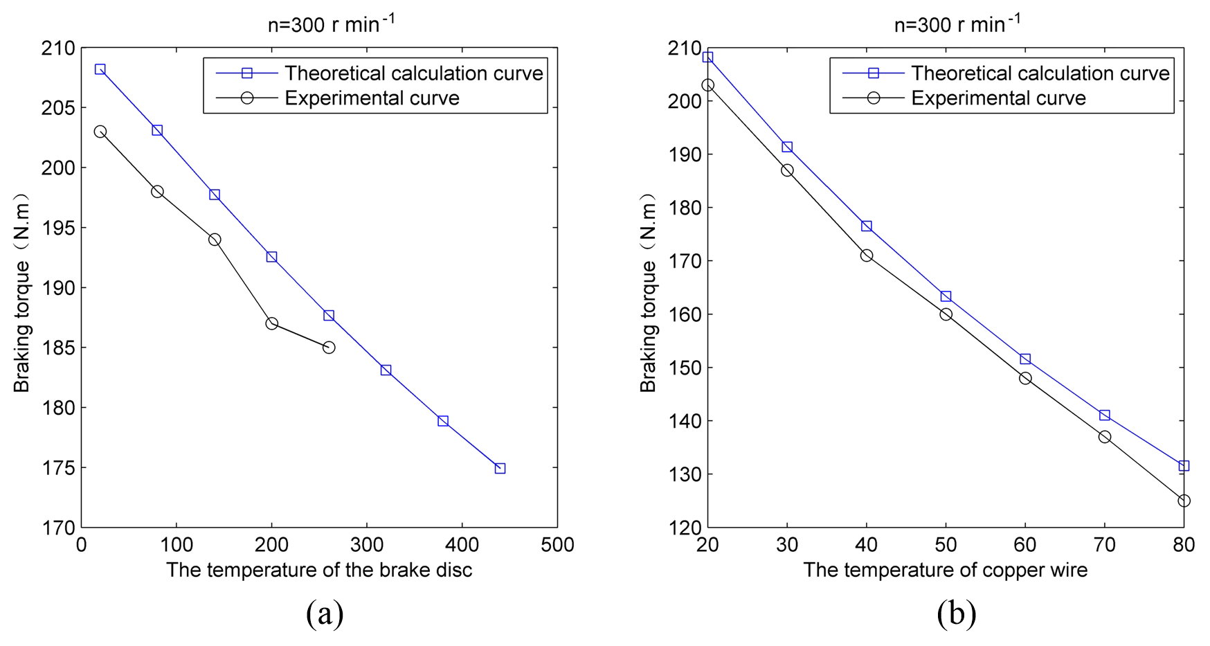
Conducting power supply and excitation coil for a long time so that copper wire temperature rises to 80∘. And then controlling the motor driven flywheel rotates to 300 r min−1 to get braking torque–temperature experimental curve as showed in Fig. 7b. Theoretical calculation curve of braking torque changing with temperature of copper wire goes well with the experimental curves. Figure 3b shows that with increasing temperature of copper wire its resistance becomes large. So the constant excitation current voltage becomes smaller. The Eq. (15) demonstrates that the intensity of the excitation current is proportionate to the air gap magnetic induction. The temperature of copper wire changing from 20 to 80∘, braking torque of electromagnetic brake reduces from 210 to 130 N m which indicates that the temperature of copper wire has a greater effect on the braking torque.
The electromagnetic brake applied in the passenger car is different from those eddy current brakes such as eddy current retarder and linear eddy current brake which their main optimization design objects are increasing their maximum braking torque. The required braking torque of passenger car may be a certain value since maximum braking intensity and braking interval of the typical city driving conditions in different countries are similar. Optimizing the energy consumption characteristics may be a research direction to enhance its usability.
4.1 Analysis of energy consumption characteristics of electromagnetic brake
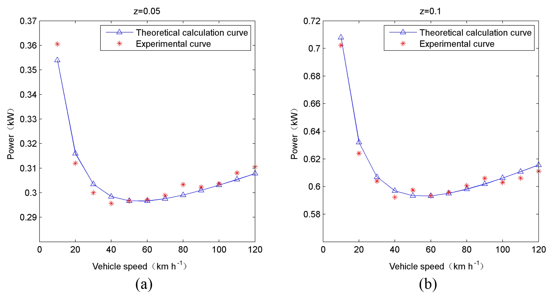
As shown in Fig. 8, the power consumption of electromagnetic energy is larger when the vehicle speed is low. With the rapid decrease of the car speed, the small slope increases slowly, and the power of electromagnetic energy consumption reaches a minimum when the vehicle speed is 50 km h−1. When the vehicle speed is in the range of 30 to 80 km h−1, the electromagnetic brake energy consumption of the electromagnetic brake principle prototype is relatively low, so this vehicle speed interval is called “low power consumption area”; When the vehicle speed is 10 km h−1, the power of electromagnetic energy is more than the minimum, and when the vehicle speed is less than 10 km h−1, the electromagnetic energy consumption will increase with a large slope. Therefore, the electromagnetic braking should be prohibited when the vehicle speed is less than 10 km h−1. Comparing with Fig. 8a and b, it can be found that the change trend of the power consumption of the electromagnetic brake that varies with the vehicle speed has nothing to do with the braking strength that vehicles demand.
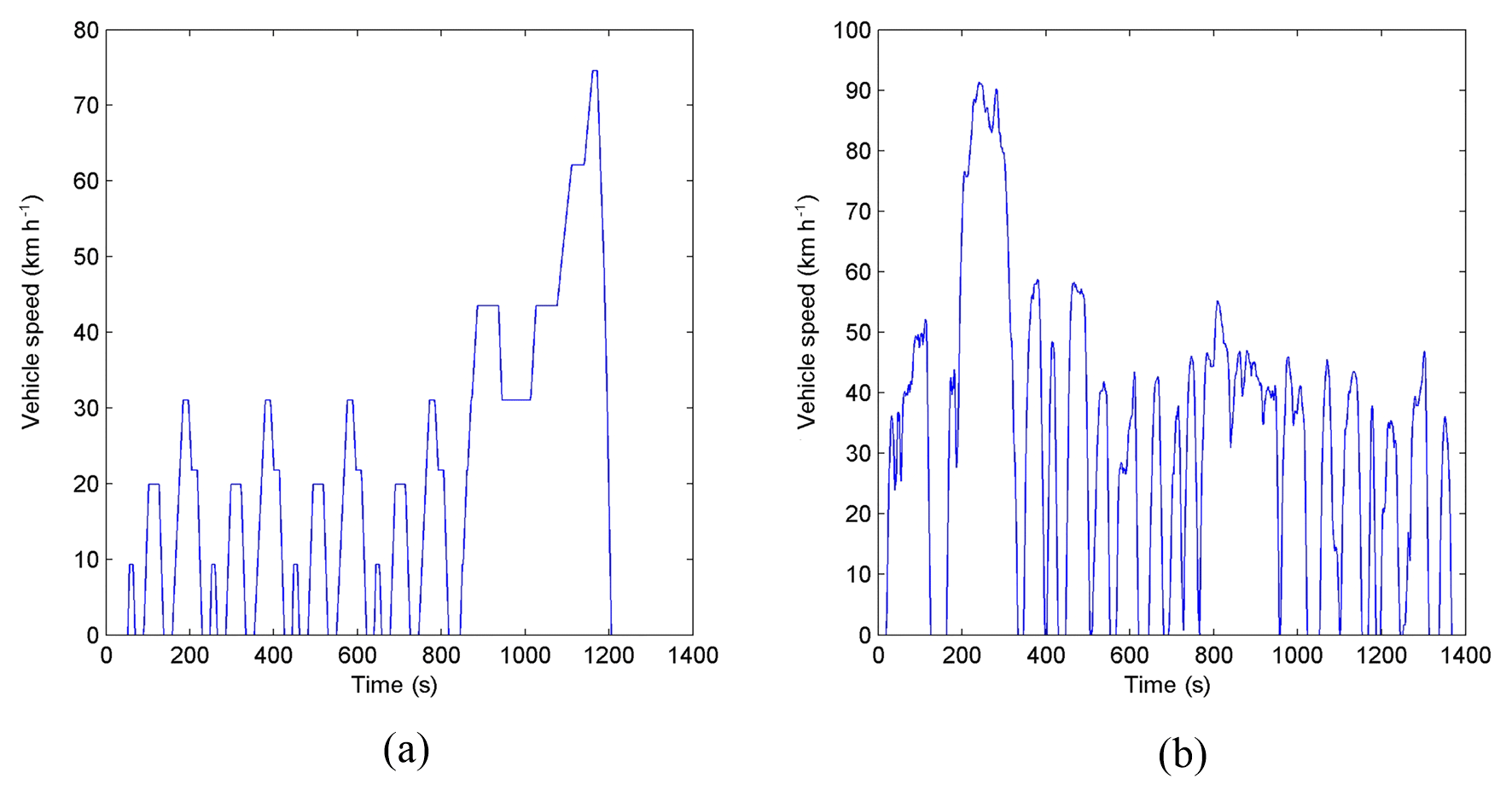
There is a “low power consumption area” corresponding to the vehicle speed range 30–80 km h−1 in which the electromagnetic brake works efficiently. Figure 9a shows the ECE–EUDC driving condition ,whose the average braking intensity is 0.079 and the biggest braking intensity is 0.139. The UDDS driving condition is shown in the Fig. 9b, whose the average braking intensity is 0.058 and the biggest braking intensity is 0.148. The average velocity of those two typical city driving conditions is 32 km h−1. According to Figs. 8 and 9, brake speed range of typical city driving conditions is 20–40 km h−1 which gets a little probability to be in the “low power consumption area”. As a result, the principles prototype of the electromagnetic brake consumes much electric energy under the typical city driving conditions. Its structure parameters should be optimized to make sure its ?low power consumption area? can include the brake speed range of typical city driving conditions to decrease its energy consumption considering the main purpose of the electromagnetic brake is to instead the friction brake under city driving conditions.
4.2 Design variables
The main optimization design variables for structural parameters of the electromagnetic brake are as follows (Xia et al., 2013):
-
The structure parameters of the exciting coil: the width and external diameter of the coil skeleton and the diameter of the iron core;
-
The structure parameters of the braking disc: the center radius of the brake disc;
-
The structure parameters of the copper wire: the diameter of copper wire.
4.3 Objective functions
According to the above analysis, the total energy consumption under ECE–EUDC driving cycle is chosen as the energy saving index and could be written as
Where n, ω1 and ω2 represent the brake times under ECE–EUDC driving cycle, the initial angular velocity of the wheel when the single brake starts and finishes, respectively.
Installing an electromagnetic brake will increase the unsprung mass which not only has an influence on the automobile dynamics performance but also leads to additional energy consumption. So that the total weight of the electromagnetic brake is required to be lighter. For the total weight of the electromagnetic brake, the weight of the iron core, the exciting coin and the brake disc account for a large part. As a result, the total weight of the electromagnetic brake can be obtained ignoring the weight of bracket:
Where, mi, mc and md represent the weight of the iron core, the weight of the exciting coin and the weight of the brake disc, respectively.
Taking such difference of the importance of these two index into consideration, the weighting coefficients are employed. The objective function can be written as:
Where, a1 is the weighting coefficient of the power consumption of electromagnetic brake. a2 is the weighting coefficient of the total weight of electromagnetic brake.
4.4 Constraint conditions
4.4.1 Electrical constraints
While limited to the electrical system of the passenger car, the current of the electromagnetic brake should satisfy the constraint condition.
Where Imax is the maximum discharge current of automobile generator, which is set as 55 A.
The selection of working point of the brake disc should make sure that the maximum magnetic induction intensity in the air gap is shorter than the saturated magnetic induction intensity of the brake disc. At the same time, the braking performance is more reliable. As a result, there represent an allowance for the braking power. The magnetic induction intensity in the air gap should satisfy the constraint condition (Jiao et al., 2014)
Where Bmax is the saturated magnetic induction intensity of soft magnetic material, and Bmax is set as 1.8 T according to Fig. 2.
Exciting coil turns the electric energy into thermal energy during braking. The insulating property of exciting coil will decrease which may result in a short circuit once the temperature of the exciting coil is beyond the permissible temperature. The maximum current density should not be larger than 8 A mm−2. The maximum current density can be presented as.
4.4.2 Space constraints
The diameter of the iron core is controlled by magnetic saturation of the exciting coil. It is required that magnetic flux density of the exciting coil cannot be saturated when the electromagnetic brake is at the maximum wheel speed. Therefore, the diameter of the iron core should satisfy the constraint condition:
Where Pmax is the maximum braking power, nmax is the corresponding speed of peak braking power.
The width of the coil skeletons is restricted by the space of the wheel. The constraint condition of the external diameter of the coil skeletons and the center radius of the brake disc can be written as:
Here rm is the center radius of the brake disc; r1 and r2 are the external and inner diameter of the brake disc respectively, respectively.
4.5 Calculation examples of optimization design
The Genetic Algorithm is utilized to obtain the global optimal solution and the constraint condition is dealt by the penalty function method. The comparison between the original parameters and the optimized parameters is shown in Table 2. The center radius of the brake disc and the external diameter of the coil skeletons are increased to the limitation of the constraint condition. Diameter of copper wire and iron core are increased to be bigger in a slight degree. The result of energy saving optimization design shows the total weight of the electromagnetic brake decreases. However, this change is insignificant which is related to the weighting coefficient of the total weight of electromagnetic brake.
Table 2Comparison between the original parameters and the optimized parameters.
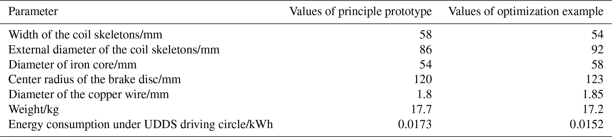
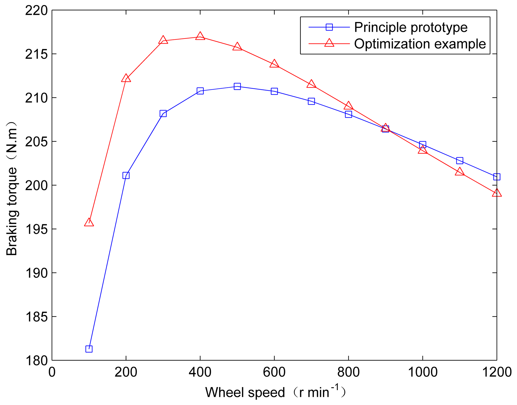
As showed in Fig. 10, the optimization results of power consumption of electricity under different speeds are better than the experimental results which also verify the energy consumption of optimization result under UDDS driving circle is lower than the principle prototype as showed in Table 2. The “low power consumption area” of the energy saving optimization design moves to the left and changes from 30–80 to 20–60 km h−1. Meanwhile, as is shown in Fig. 11, the curve of peak braking torque only increased 5∘ N m. However, critical speed changes from 500 to around 350 r min−1.
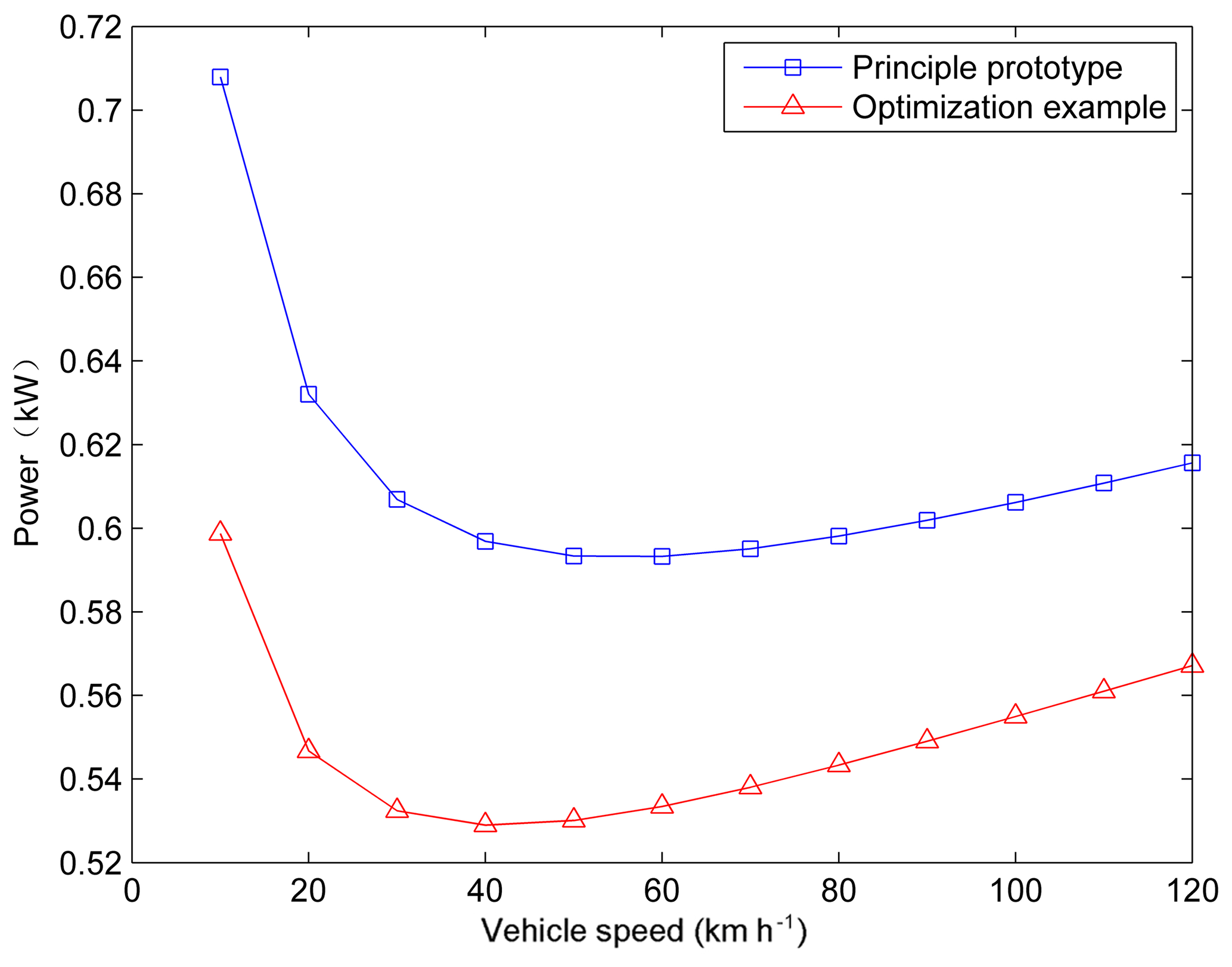
Figure 10Correlation curves of the power consumption of electricity before and after the optimization design.
5.1 Influence of thermodynamic properties on energy consumption of electromagnetic brake
Involving in the control of the electromagnetic brake, there are two problems needing to be solved. One is the way that how to control the exciting windings when braking, namely the brake task allocation between the excitation windings. The other is the distribution of electromagnetic braking torque in the automobile front and rear axles.
It can be pointed out in Eq. (3) that the resistance value of the excitation winding increases because of its temperature rise during a long time working. And the additional electricity consumption will be generated to ensure the demanded exciting current to be a constant basing on Eqs. (16) and (18). If the other conditions are unchanged, the output braking torque of electromagnetic brake would have a certain degree of attenuation as the temperature of brake disc rises. In order to maintain the demand braking torque, more energy is needed for the electromagnetic brake. Therefore, it is necessary to study the influence of the thermodynamic properties on the energy consumption of electromagnetic brake.
The energy into the control body are required to be equal to the sum of the energy which leaves the control body and its storage energy per unit time according to the energy conservation law (Agrawal, 2004). In the thermodynamics analysis, the following assumptions should be made to simplify the analysis: (1) The air temperature around the electromagnetic brake is consistent with the environment temperature (Limpert, 1975). (2) Due to the low electromagnetic braking torque, it is assumed that there is no slip between the tire and the road. (3) Heat conduction occurs only inside the braking parts and the external cooling could be negligible in the continuous working process of the electromagnetic brake. (4) The temperature distribution in the brake disc is assumed to be uniform for the strong thermal conductivity of the brake disc.
When the electromagnetic brake works, the vehicle's kinetic energy is converted into thermal energy to be dissipated. Part of the thermal energy is stored in the brake disc causing the rise of brake disc temperature and another part of the thermal energy is sent out into the air by the constantly rotating brake disc (Artus et al., 2005).
Where, Pe is the absorbed heat energy of the electromagnetic brake per unit time, namely the electromagnetic braking power. Pd is the heat energy released by the brake disc per unit time. Q is the stored thermal energy of the brake disc per unit time.
The heat energy released by brake disc per unit time can be calculated by the following equation (Ali and Mostefa, 2014):
Where hd is the sum of the convective heat transfer coefficient and the radiation heat transfer coefficient of the brake disc; Ad is the effective heat dissipation area of the brake disc. Td0 and Td1 are the brake disc temperature before and after braking respectively.
For solid brake disc, when , the convective heat transfer coefficient can be expressed as:
Where D is the diameter of the brake disc, Ka is the thermal conductivity of air
When , the convective heat transfer coefficient can be expressed as:
The Reynolds number Re is defined as the ratio of the inertial force and friction force for the fluid flow with the expression of:
Where v is the kinematic viscosity of air, ρa is the air density. μa is the air viscosity, Ld is a defined characteristic length defined by Reynolds number.
The radiation heat transfer coefficient of the brake disc is determined by the following equation:
Where σ is the Stephen-boltzmann constant; ε is the radiation rate of the brake disc.
The heat stored by the brake disc per unit time can be calculated by the following equation:
Where Md is the mass of brake disc; cd is the specific heat of brake disc; Td(t+Δt) is the temperature of the brake disc at time t+Δt; Tdt is the temperature of the brake disc at time t.
If Δt→0, the Eq. (34) would be transferred into:
Substituting Eqs. (14), (29) and (35) into Eq. (28), it is available to get the transient temperature expression of the brake disc:
The transient temperature analysis of the exciting winding is similar to the analysis above and does not have to be repeated here. According to the analysis above, the temperature of the exciting winding and the brake disc increases with the raise of braking time and braking intensity which further improves the exciting winding resistance and current leading to more energy consumption of the electromagnetic brake. In this case, the study on the electromagnetic brake control method to make it use minimal power for the same brake task is becoming very meaningful.

Figure 12Temperature rising curves of the excitation winding with different magnetic pole logarithmic.
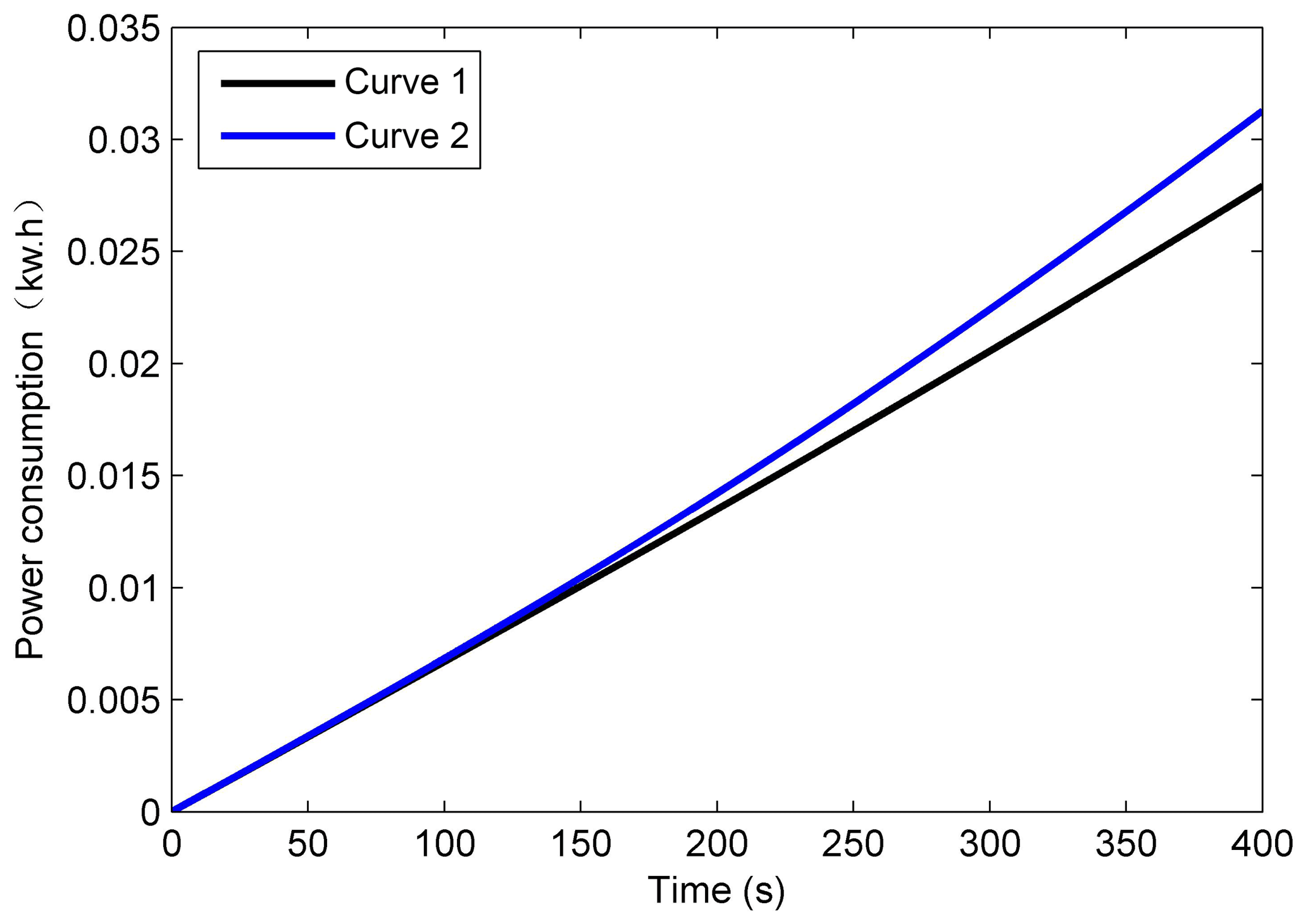
Figure 13Energy consumption curves of electromagnetic brake under different magnetic pole logarithmic.
5.2 Energy saving control method for electromagnetic brake
In this paper, two sets of experiments have been designed. Firstly, we use two groups of exciting windings and four groups of exciting windings respectively to ensure the same braking torque as shown in Figs. 12 and 13. The curve 1 is the experimental results using all four groups of the exciting windings. And the curve 2 is the experimental results only using two groups of exciting windings. During these two situations, the output braking torque of electromagnetic brake is kept in 100 N m and the wheel speeds are 400 r min−1. The braking power of using all four groups of the exciting winding is less than that of only using two groups as is shown in Fig. 13. The absorption braking energy and temperature rise of the brake disc are almost the same for the braking torque and rotational speed are the same. While the Fig. 12 shows that the excitation winding temperature of using all the exciting winding increases more slowly which has lower increasing amplitude than that of only using two groups too which suggests that the higher excitation winding temperature is a major cause leading to the poor energy consumption characteristics for using only two groups of excitation windings.
Then the braking force would be distributed to the front axle's electromagnetic brake or allocated equally to the front and rear axle's electromagnetic brakes. The total power consumptions of these two situations are shown in Fig. 14 with the wheel speed remaining at 400 r min−1 and the braking torque keeping 100 and 200 N m respectively. Obviously, for the temperature of both the excitation winding and the brake disc, the larger the output brake torque is, the higher the corresponding temperatures as shown in Figs. 15 and 16. It can be seen that the power consumption in the situation by distributing all the braking force on one axle is more than distributing equally to the front and rear axles. The higher excitation winding and brake disc temperatures are still the major cause leading to excessive energy consumption.
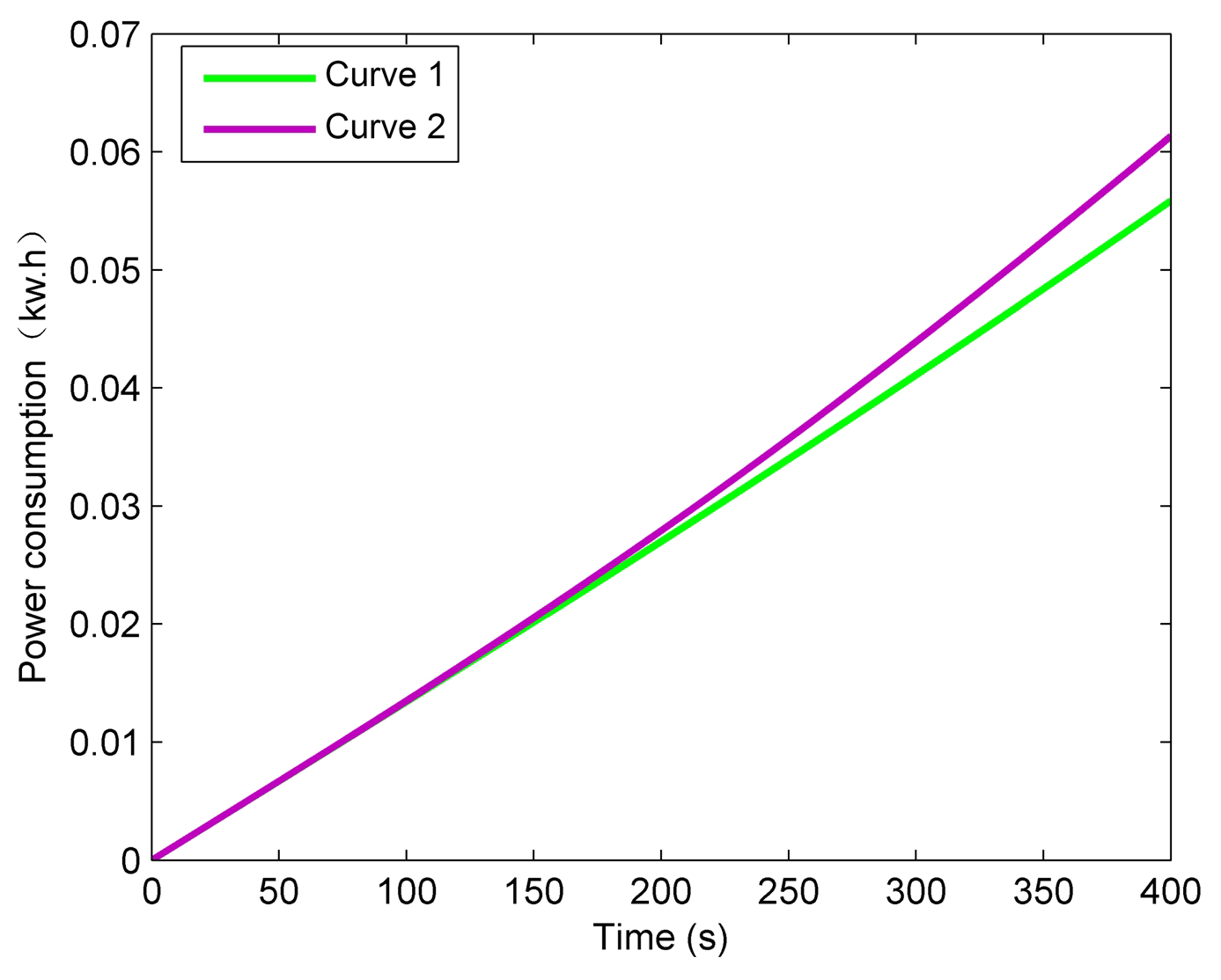
Figure 14Energy consumption characteristic curves of the electromagnetic brake under different braking situations.
According to the conclusions analyzed above, distributing the brake task equally can prevent the temperature of the exciting windings and the brake disc to rise too high which could reduce the energy consumption in the process of using the electromagnetic brake. The corresponding energy saving control methods of electromagnetic brake are that all the exciting windings should be controlled to work with the same excitation current and when distributing the electromagnetic braking force to the front and rear axles, the electromagnetic braking torque should be distributed according to the ideal braking force distribution curve considering the limit of the braking regulations since the main purpose of electromagnetic brake is to instead the friction brake under the city driving conditions.
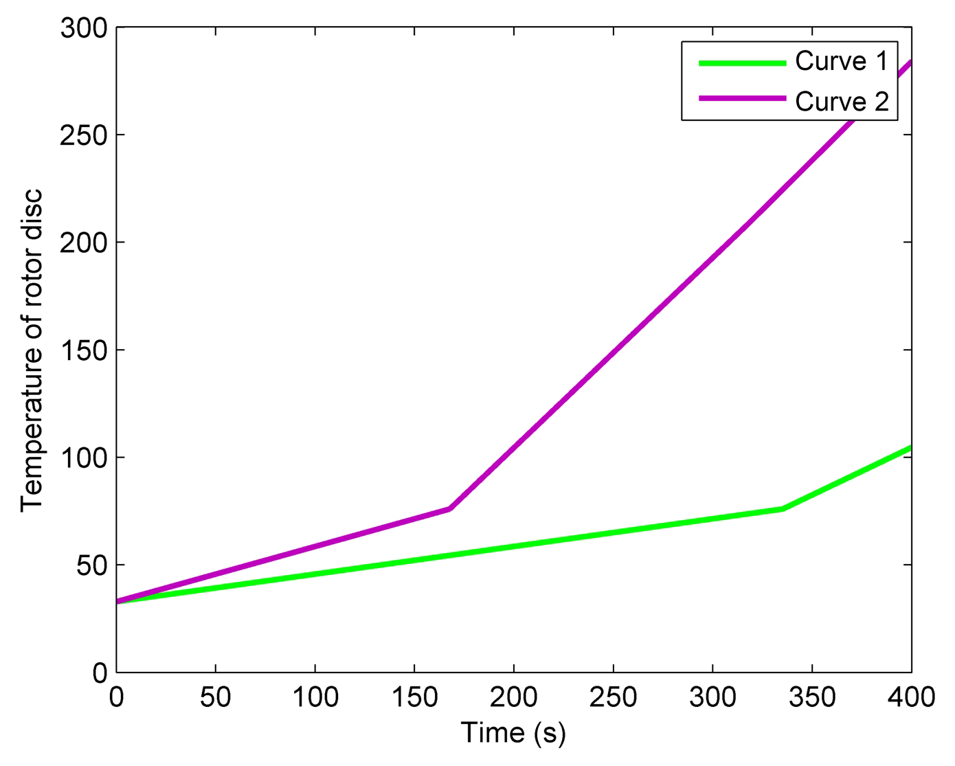
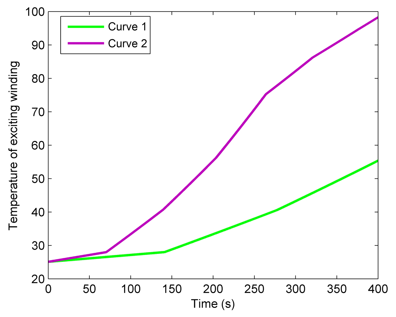
Figure 16Temperature rising curves of the exciting winding under different braking situations.
In this article, prediction models of the braking performance and power consumption of electromagnetic brake are established and their accuracies are verified on the hardware in the loop simulation platform. The electromagnetic brake is designed aiming at reducing the energy consumption and the energy saving control method of electromagnetic brake is also proposed. Conclusion can be gained as follows:
-
The prediction model of braking performance and power consumption established above can describe the influence of the nonlinear properties of materials on the braking torque and the energy consumption very well which could also be used in the design and control of other eddy current brakes.
-
There is a “low power consumption area” existing in the power consumption curve of the electromagnetic brake with the vehicle speed. The electromagnetic brake design is carried out from the respective of the “low power consumption area” containing the initial braking speed range of typical urban driving conditions, which is beneficial to reduce the power consumption of the electromagnetic brake in actual use.
-
By analyzing the effect of thermodynamics characteristics of electromagnetic brake on its energy consumption characteristics, we can get that the more number of pole pairs is the more energy-saving it may be in the process of the actual use. The energy saving optimization design for electromagnetic brake does not take into account of that in this paper. So it is necessary to further study on energy-saving optimal design method considering the change of the number of pole pairs.
All the data used in this manuscript can be obtained by request from the corresponding author.
The main contribution for DH includes the structural design, modeling analysis and the control. The contribution for co-author YY includes the structural optimization, construction of simulation platform and manuscript writing. And the contribution for co-author XX includes the structural design and the English writing error and grammar modification.
The authors declare that they have no conflict of interest.
This research is supported by the National Natural Science Foundation of
China (grant no. 51705208), China Postdoctoral Science Foundation (grant no.
2018M632240) and Shandong Agricultural Machinery Equipment Research and
Development Innovation Project (grant no. 2018YF018).
Edited by: Jahangir Rastegar
Reviewed by: four
anonymous referees
Agrawal, O. P.: Application of fractional derivatives in thermal analysis of disk brakes, Nonlinear Dynam., 38, 191–206, https://doi.org/10.1007/s11071-004-3755-7, 2004.
Ali, B. and Mostefa, B.: Structural and Thermal Analysis of Automotive Disc Brake Rotor, Archive of Mechanical Engineering, 61, 89–113, https://doi.org/10.2478/meceng-2014-0005, 2014.
Anwar, S.: Generalized predictive control of yaw dynamics of a hybrid brake-by-wire equipped vehicle, Mechatronics, 15, 1089–1108, https://doi.org/10.1016/j.mechatronics.2005.06.006, 2005.
Anwar, S. and Stevenson, R. C.: Torque characteristics analysis of an eddy current electric machine for automotive braking applications, in: Proceedings of the 2006 American Control Conference, 14–16 June 2006, Minneapolis, Minnesota, USA, 2006.
Artus, S., Cocquempot, V., Hayat, S., Staroswiecki, M., Larminat, P. D., and Covo, C.: CHV's brake discs temperature estimation: results in open road tests, in: Proceedings of the 2005 IEEE Intelligent Transportation Systems, 16–16 September 2005, Vienna, Austria, 2005.
Gay, S. E. and Ehsani, M.: Analysis and experimental testing of a permanent magnet eddy-current brake, in: Proceedings of the 2005 IEEE Vehicle Power and Propulsion Conference, 7–9 September 2005, Chicago, Illinois, USA, 2005.
Gay, S. E. and Ehsani, M.: Parametric analysis of eddy-current brake performance by 3-D finite-element analysis, IEEE T. Magn., 42, 319–328, https://doi.org/10.1109/TMAG.2005.860782, 2006.
He, R., Liu, X., and Liu, C.: Brake Performance Analysis of ABS for Eddy Current and Electrohydraulic Hybrid Brake System, Math. Probl. Eng., 2013, 1–11, https://doi.org/10.1155/2013/979384, 2013.
Hu, D. H., Yan, Y. Z., and Xu, X. M.: Determination methodology for stable control domain of electric powertrain based on permanent magnet synchronous motor, Adv. Mech. Eng., 10, 1–13, https://doi.org/10.1177/1687814018793053, 2018a.
Hu, D. H., Yan, Y. Z., and Li, Z. Y.: Optimization methodology for control parameter of PI based on chaos prediction of electric powertrain, AIP Adv., 8, 095115, https://doi.org/10.1063/1.5050031, 2018b.
Hu, D. H., Yan, Y. Z., and Li, Z. Y.: Optimization methodology for coasting operating point of high-speed train for reducing power consumption, J. Clean Prod., 212, 438–446, https://doi.org/10.1016/j.jclepro.2018.12.039, 2019.
Jian, M. A., Yin, S. C., Qiang, Y. U., and Guo, R. Q.: The Application Study of Retarder to Automobile Driving down Slope Road, Journal of Xian Highway University, 19, 84–86, https://doi.org/10.19721/j.cnki.1671-8879.1999.04.025, 1999.
Jiao, B., Li, D., Du, X., and Zhang, K.: Performance Analysis and Experimentation of a Liquid-Cooled Eddy Current Retarder With a Dual Salient Poles Design, IEEE T. Energy Conver., 29, 84–90, https://doi.org/10.1109/tec.2013.2288695, 2014.
Karakoc, K., Suleman, A., and Park, E. J.: Optimized Braking Torque Generation Capacity of an Eddy Current Brake With the Application of Time-Varying Magnetic Fields, IEEE T. Veh. Technol., 63, 1530–1538, https://doi.org/10.1109/TVT.2013.2286097, 2014.
Limpert, R.: The thermal performance of automotive disc brakes, SAE Technical Paper 750873, https://doi.org/10.4271/750873, 1975.
Liu, C. and He, R.: Structure Analysis of Composition of Frictional Brake and Contactless Wheel Retarder System, Transactions of the Chinese Society of Agricultural Machinery, 41, 25–30, https://doi.org/10.3969/j.issn.1000-1298.2010.06.005, 2010.
Park, M. G., Choi, J. Y., Shin, H. J., and Myeong, J. S.: Torque analysis and measurements of a permanent magnet type Eddy current brake with a Halbach magnet array based on analytical magnetic field calculations, J. Appl. Phys., 115, 17E707, https://doi.org/10.1063/1.4862523, 2014.
Pernestal, A., Nyberg, M., and Warnquist, H.: Modeling and inference for troubleshooting with interventions applied to a heavy truck auxiliary braking system, Eng. Appl. Artif. Intel., 25, 705–719, https://doi.org/10.1016/j.engappai.2011.02.018, 2012.
Um, Y., Torii, S., Ebihara, D., and Sanjo, I.: Characteristic of eddy current on the secondary of eddy current brake, in: Proceedings of the 1997 IEEE International Electric Machines and Drives Conference, 18–21 May 1997, Milwaukee, Wisconsin, USA, 1997.
Um, Y., Torii, S., Ebihara, D., Sanjo, I., and Tani, Y.: Measuring method of the magnetic field on an eddy current brake, IEEE T. Magn., 35, 3934–3936, https://doi.org/10.1109/20.800713, 1999.
Venkataratnam, K. and Kadir, A.: Analysis and performance of eddy-current brakes with ferromagnetic loss drums. Part 1: Nonsalient-pole brakes, IEE P.-Elect. Pow. Appl., 129, 125–131, https://doi.org/10.1049/ip-b.1982.0018, 1982a.
Venkataratnam, K. and Kadir, A.: Analysis and performance of eddy-current brakes with ferromagnetic loss drums. Part 2: Salient-pole brakes, IEE P.-Elect. Pow. Appl., 129, 132–142, https://doi.org/10.1049/ip-b.1982.0019, 1982b.
Wang, P. J. and Chiueh, S. J.: Analysis of eddy-current brakes for high speed railway, IEEE T. Magn., 34, 1237–1239, https://doi.org/10.1109/20.706507, 1998.
Xia, W., Tan, G., Wang, S., and Wang, J. M.: Experiment Study and Design of Self-excited Eddy Current Retarder, SAE Technical Paper 2013-01-2825, https://doi.org/10.4271/2013-01-2825, 2013.
Zhang, D., He, R., and Gu, X.: Calculation and Analysis on the Braking Force of Vehicle Electromagnetic Brake, Automot. Eng., 35, 904–907, https://doi.org/10.19562/j.chinasae.qcgc.2013.10.010, 2013.
Zhang, K., Li, D., Du, X., and Zheng, R.: Numerical Analysis and Experimentation of a Novel Self-Excited and Liquid-Cooled Eddy Current Retarder, IEEE T. Energy Conver., 29, 196–203, https://doi.org/10.1109/tec.2013.2295218, 2014.
Zhao, W. Z. and Zhang, H.: Coupling control strategy of force and displacement for electric differential power steering system of electric vehicle with motorized wheels, IEEE T. Veh. Technol., 67, 8118–8128, https://doi.org/10.1109/TVT.2018.2850154, 2018.
Zhao, W. Z., Zhang, H., and Li, Y. J.: Displacement and force coupling control design for automotive active front steering system, Mech. Syst. Signal Pr., 106, 76–93, https://doi.org/10.1016/j.ymssp.2017.12.037, 2018a.
Zhao, W. Z., Luan, Z. K., and Wang, C. Y.: Parametric optimization of novel electric–hydraulic hybrid steering system based on a shuffled particle swarm optimization algorithm, J. Clean Prod., 186, 865–876, https://doi.org/10.1016/j.jclepro.2018.03.180, 2018b.
- Abstract
- Introduction
- Electromagnetic brake of passenger car
- Performance prediction model of electromagnetic brake
- Energy saving optimal design of electromagnetic brake
- Energy saving control method of electromagnetic brake
- Conclusion
- Data availability
- Author contributions
- Competing interests
- Acknowledgements
- References