the Creative Commons Attribution 4.0 License.
the Creative Commons Attribution 4.0 License.
 | 18 Jul 2019
Tool Wear Progression and its Effect on Energy Consumption in Turning of Titanium Alloy (Ti-6Al-4V)
Muhammad Younas
Syed Husain Imran Jaffery
Riaz Ahmad
Liaqat Ali
Zarak Khan
Aftab Khan
To achieve greater productivity, titanium alloy requires cutting at higher speeds (above 100 m min−1) that affects the tool life and energy consumption during the machining process. This research work correlates the wear progression and Specific Cutting Energy (SCE) in turning Ti-6Al-4V alloy using H13 tools (uncoated carbide) in dry conditions from low to high cutting speeds. Cutting condition employed in this study were selected from published wear map developed for titanium (Ti-6Al-4V alloy) with the same tool. Flank wear growth of the tool has been investigated at different length of cuts in correlation with the SCE under different cutting conditions. The useful tool life was found to be shorter at high-speed machining conditions, thus the end of useful tool life criteria (ISO 3685) was reached at a much shorter length of cuts as compared to low-speed machining conditions. The cutting conditions corresponding to high wear rate also resulted in high SCE. Finally, SCE and wear have been related by a linear relationship that can be used to monitor wear and/or SCE utilization during machining. The results help in the selection of appropriate cutting conditions that will enhance the tool life and minimize SCE consumption during machining titanium alloy.
- Article
(2904 KB) - Full-text XML
- BibTeX
- EndNote


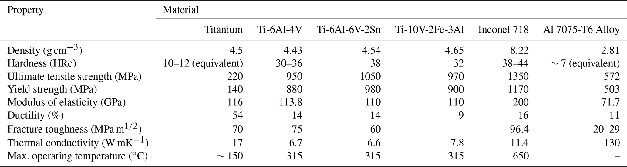
Titanium alloys have well-known applications that include automotive, aerospace as well as biomedical implants owing to their excellent properties, higher strength to density ratio and remarkable corrosion resistance (Arrazola et al., 2009; Ezugwu et al., 2003). Unalloyed titanium that has α phase have lesser strength when compared to titanium alloys presented Table 1. But when titanium is alloyed with elements like molybdenum, vanadium and aluminum it shows remarkable properties like higher strength and hardness that makes them suitable for a variety of industries as well as other applications. Despite all this, machining this alloy still is a major challenge to the manufacturers and is considered as difficult to cut material owing to its properties like chemical reactiveness and small conductivity values (Jaffery et al., 2013; Zoya and Krishnamurthy, 2000; Deng et al., 2008). Thus these alloys are considered as material posing high tool wear, shorter tool life, low material removal rates, poor surface quality and higher cutting temperatures (Ezugwu et al., 2003; Hughes et al., 2006; Sun and Guo, 2009).
Table 1Comparison of room temperature properties of aerospace alloys (Jaffery et al., 2013; Jaffery and Mativenga, 2012; Hughes et al., 2006).
In recent years, special attention has been paid by several researchers to overcome major difficulties in cutting titanium alloy due to growing production demands. These efforts include the improvement of cutting tools using coating materials (Jaffery and Mativenga, 2012; Li et al., 2018a; Kuram, 2018; Kumar et al., 2018), identification of the most favorable process parameters for wear minimization (Li et al., 2018b; Revuru et al., 2018), optimization of multiple responses (Gupta et al., 2018) and improving the existing tool design as well as use of cryogenic machining (Shokrani et al., 2018). One of the prime challenges also includes a reduction in energy demands during machining titanium alloy. Material characteristics and the process parameters used in cutting operation influences the energy consumed during machining (Balogun and Mativenga, 2014). Therefore, researchers have focused on different strategies to minimize the energy consumption during machining that includes the selection of optimum process parameters or the development of effective numerical models for machine tools (Warsi et al., 2018a, b).
Machining superalloy like titanium and nickel alloy continued as a topic of interest for industries and researchers all together. Since titanium alloy sustain their strength at elevated temperatures due to which temperature at the chip-tool interface can reach up to 1000 ∘C while machining Ti-6Al-4V at higher cutting speed (Venugopal et al., 2007a, b). As a result, rapid wear of the cutting tool occurs, and shorter tool life is observed. Several studies have reported the mechanism of tool wear during machining titanium alloy. For monitoring the tool wear, wear maps have been presented by various researchers for selecting cutting condition that results in best wear performance of the tool. In case of turning titanium Ti-6Al-4V, a wear map was published (Jaffery and Mativenga, 2009) that plots the flank wear rate on the cutting speed Vs. feed rate plot. Li et al. (2012) also reported a detailed experimental study of tool wear progression during milling of Ti-6Al-4V alloy using carbide tools at high speed. The study underlined that cutting forces with the temperature increased as the cutting velocity is increased resulting in accelerated tool wear growth during machining. In another study, Bermingham et al. (2011) analyzed cryogenic turning of Ti-6Al-4V to analyze the effect of feed and depth of cut on tool life, wear, cutting forces and the chip morphology. Improved tool life was observed as the cryogenic coolant helped in reducing the heat generated during the machining process. A detailed study on the tool wear progression for uncoated carbide tool in dry, wet and cryogenic environment was carried out by Venugopal et al. (2007b). It was found that cryogenic cooling improved the tool life significantly at low cutting speed but at high speed, the coolant could not penetrate properly in the contact zone. The authors also reported that the smaller contact length was the main reason for the increase in temperature and hence promoting tool wear in dry cutting conditions. However, the correlation between the tool wear and SCE during machining titanium alloy have not been presented by the previous researchers.
Strategies targeted for energy minimization have also gained a lot of interests in recent years and several studies have been reported for energy analysis in various machining processes. Some notable contributions for energy modeling and cost reduction as well as sustainable manufacturing strategies for machining can be found in following literature (Mativenga et al., 2011; Behrendt et al., 2012; Kara and Li, 2011). The Specific consumption energy (SCE), which is the energy consumed in removing a unit volume of the material, can also be controlled by machinist through careful selection of the process parameters as it depends on the machinability of material and the cutting conditions during operation (Balogun et al., 2015). As the energy consumption during machining hard materials such as titanium is also affected by the tool wear, this research focuses on the effect of the tool flank wear progression on the SCE during dry turning Ti-6Al-4V in different cutting situations. Wear map published by Jaffery and Mativenga (2009) was used to identify cutting parameters in three important zones low, moderate and high tool wear zone. These conditions were used to evaluate the effect of increasing tool wear on the SCE in turning Ti-6AL-4V titanium alloy.
Titanium alloy machining has not been investigated in term of energy consumption like other engineering materials. In case of soft materials like aluminum, it has been reported that the tool wear is negligible and hence the machining process does not affect the SCE consumed during the actual cutting process (Warsi et al., 2018b). For the case of titanium alloy, the tool wear severely affects the energy consumed for the actual cutting operation. Therefore, current research is carried out to know the impact of flank wear growth on specific cutting energy in turning carried out for titanium alloy (Ti-6AL-4V), as the energy consumed is affected by the tool blunting and wear continuously. As a final point, knowing the energy demands of difficult to cut materials like titanium require such study as it is helpful to identify the right combination of feed and speed that reduces the SCE and promote economic machining. The energy measured at the beginning of the process and the end of useful tool life will be different due to wear growth, which will also produce variations in SCE as well as the surface roughness of the part. The study is meaningful as it will also provide a strong basis for producing alternative tool material as well as increasing the machining efficiency. This work presented here has identified the correlation between wear and SCE in turning Ti-6AL-4V at different machining conditions.
2.1 Workpiece material and cutting tool
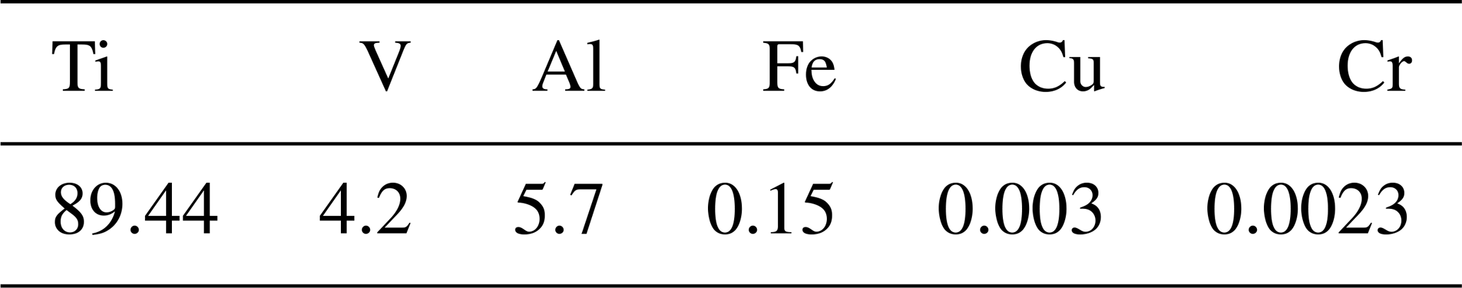
Titanium Ti-6Al-4V bar was used in this study as the workpiece material having length 300 mm and diameter 70 mm. The mechanical properties and chemical composition of the workpiece material are given in Table 1 (Hughes et al., 2006; Jaffery et al., 2016) and Table 2. Uncoated CCMW 09 T3 04 H13 cutting inserts (produced by SANDVIK) without chip breaker having 0 rake angle were used to perform turning experiments. Computer numerical control (CNC) Turning Center ML-300 manufactured by YIDA Precision Machinery Co., Ltd, having spindle power 15 kW and total power of 26 KW was used to carry out dry turning. The maximum spindle speed of 3400 rev min−1 could be achieved using this CNC machine. Experiments were conducted in steps of equal cutting length in the axial direction, till the end of the useful life of the tool. Each experimental run used a fresh cutting insert.
Table 2Composition (wt %) of Ti-6Al-4V alloy used in experiments.
2.2 Measurement of specific cutting energy
The cutting power during machining was measured using clamp-on meter Yokogawa CW 240. This power analyzer is capable of measuring power, voltage, current and power factor of the CNC machine and can record it for an interval of up to 0.1 s. The measurements were done in two-cycle; recording air cut power (Pair) and actual cut power (Pactual). This approach has also been used by previous researchers (Warsi et al., 2018b; Li and Kara, 2011) for measuring and recording power data. Figure 1 shows the Pair and Pactual recorded during a cutting condition. The difference between the two power gives the power (Pcut) needed for material removal during the cycle is given in Eq. (1).
SCE is the energy needed for removing a unit volume of material and expressed commonly in units of J mm−3. Specific cutting energy was measured using Eq. (2).
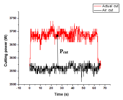
Figure 1The recorded actual and air cut power to calculate cutting power at cutting condition (v=50 m min−1, f=0.12 mm per rev and d=1 mm).
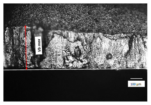
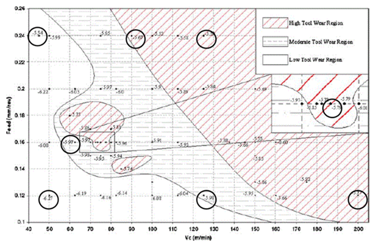
Figure 3Wear map adopted from Jaffery and Mativenga (2009) with cutting conditions for study highlighted.
Air cut energy was recorded when the machine tool was not involved in cutting and the machine is ready to perform cutting operation with all its components electrically energized. Whereas, actual cutting energy recorded when the tool workpiece was engaged in cutting operation. The methodology has also been used by previous researchers (Warsi et al., 2018b; Li and Kara, 2011) for estimating SCE.
2.3 Wear measurement
Wear of the inserts was analyzed and measured according to ISO standard 3685; standard for tool life testing (ISO, 1993). The rejection criteria for cutting tools during the experiments remained as localized flank wear VB=0.3 mm as well as the fracturing and chipping of the tool cutting edge. Figure 2 shows the wear measurement using an optical microscope. The wear progression and energy for each cutting condition were analyzed where machining was interrupted after a cutting length till the end of useful tool life. The variation in the SCE as the tool wear progresses was measured and recorded for each experiment as presented in Figs. 1 and 2.
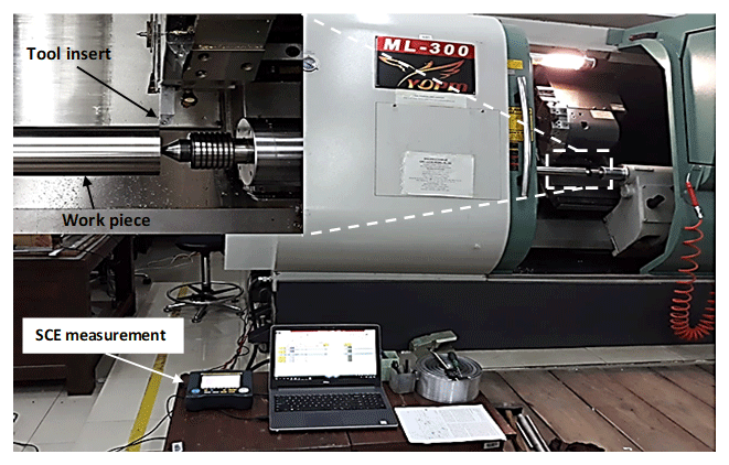
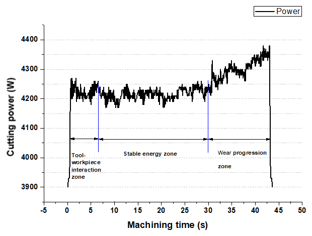
Figure 5Energy zones during machining titanium (Ti-6Al-4V) alloy at speed, V=200 m min−1, feed rate, f=0.12 mm per rev and depth of cut, d=1 mm.
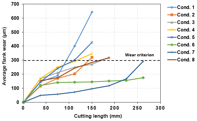
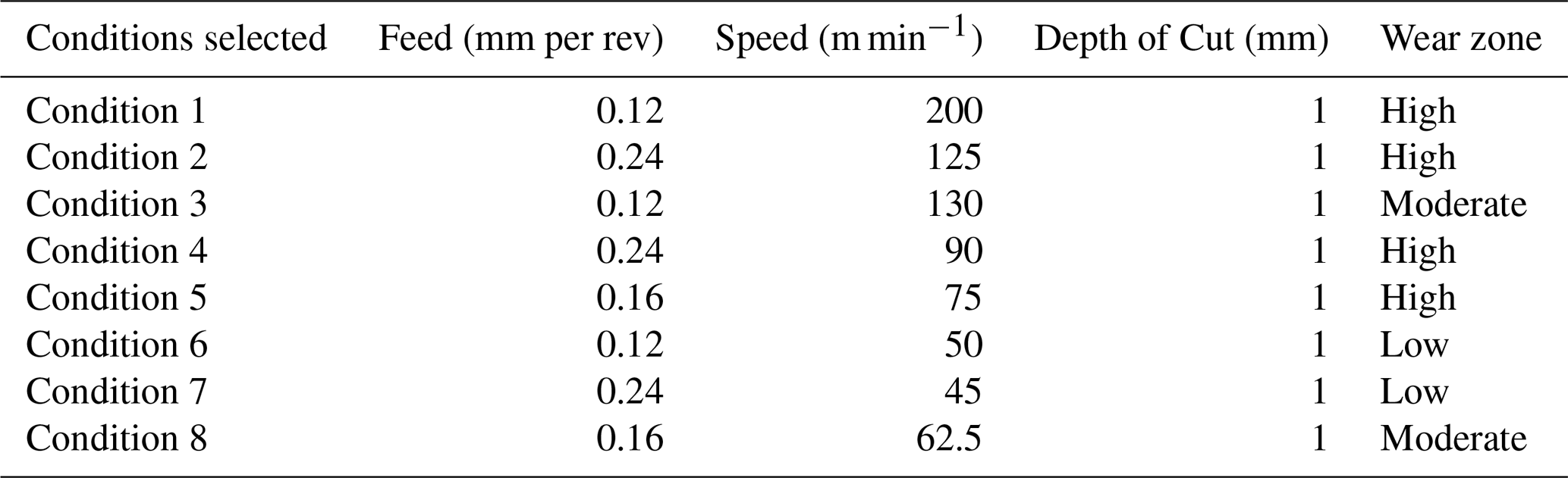
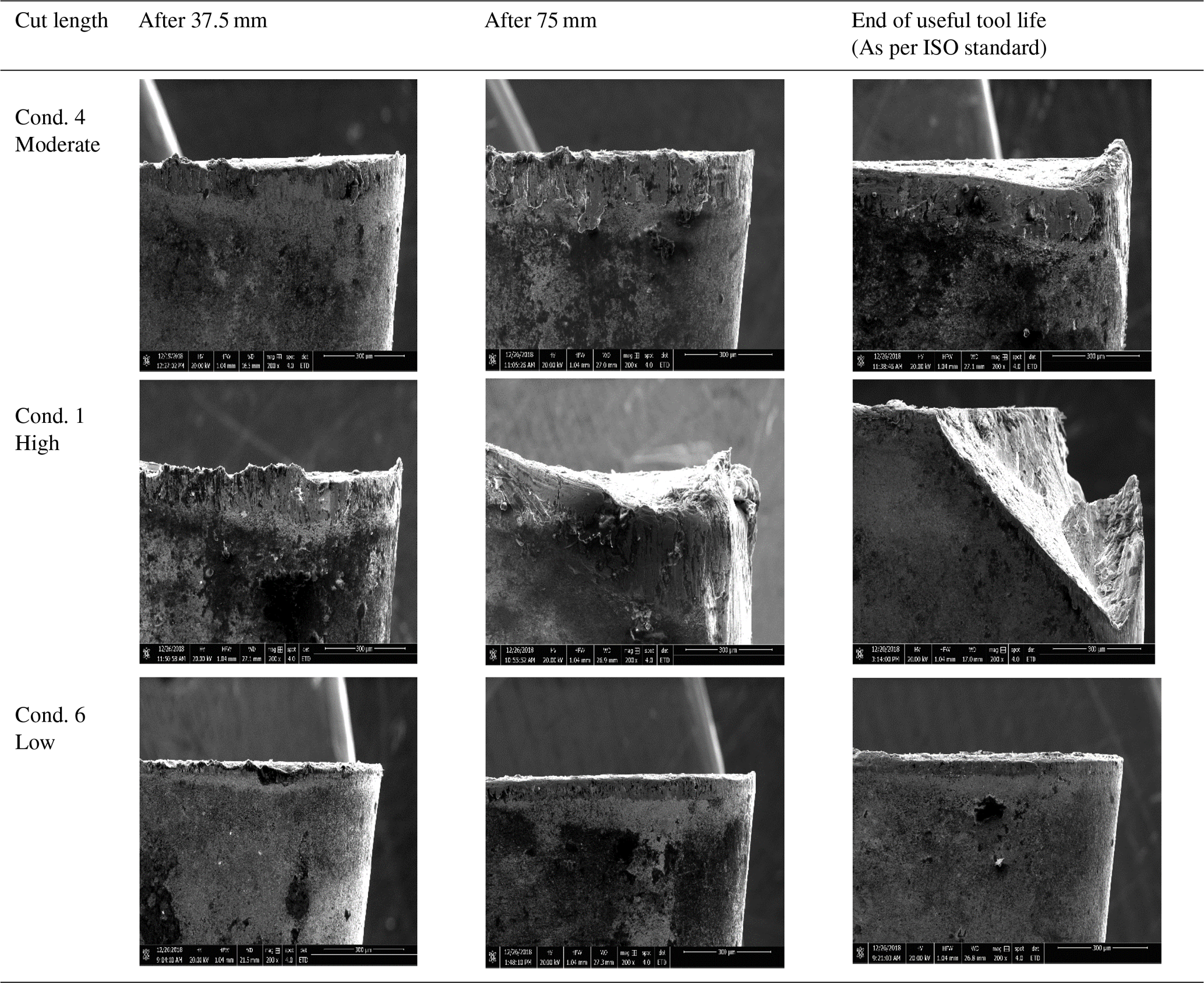
Table 4SEM Micrographs of thr inserts showing wear at different length of cuts.
The cutting conditions were selected from wear map published previously by Jaffery and Mativenga (2009), including cutting condition from the high, moderate and low wear region as highlighted in Fig. 3. These machining conditions are presented in Table 3. The selected cutting conditions from the map are well in agreement with the tool manufacturer recommended conditions (f = 0.08–0.26 mm per rev, V = 0–250 m min−1 and d = 0–4 mm) for H13 cutting inserts (Sandvik, 2015). The experimental setup used in turning titanium under dry conditions for the selected conditions is shown in Fig. 4. The clamp on power meter was mounted at the main control of the CNC machine and power during actual cutting for each experimental run was recorded at the meter. Similarly, the tool wear in each experimental run was studied in steps where the machine was stopped after a specified length of cut and the wear was observed in the microscope till the end of tool life.
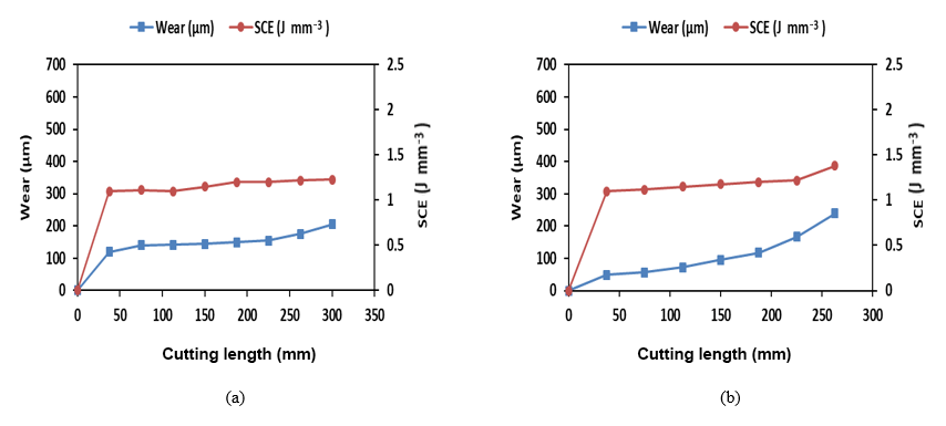
Figure 7Variation in the SCE due to increase in the wear at different cutting lengths for (low wear region conditions); (a) Condition 6 (V=50 m min−1, f=0.12 mm per rev), (b) Condition 7 (V=45 m min−1, f=0.24 mm per rev).
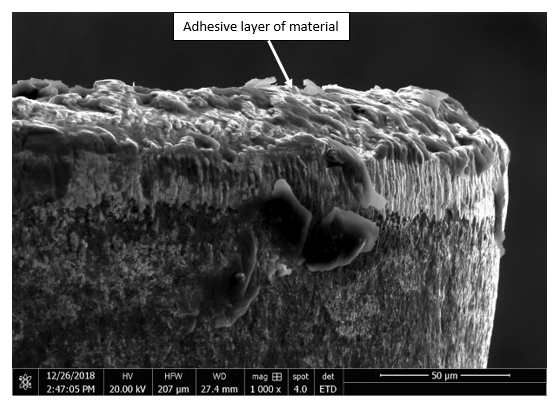
Figure 8SEM image showing the adhesion of material on rake face at low speed (V=50 m min−1).
4.1 Energy zones during machining Ti-6Al-4V
The energy recorded was analyzed for each experimental condition and three important zones on the cutting power-time graph were observed as shown in Fig. 5. The first zone corresponds to the start of the machining cycle where tool-workpiece interaction occurs and thus produces variation in the power values recorded due to chattering at the start of cutting (Tool-work-piece interaction zone). The second zone corresponds to the stable energy zone where the tool- workpiece interaction occurs smoothly without fluctuation in power recorded (stable zone). The third zone represents the region in which the increased power fluctuation is observed as the tool wear starts progressing along the flank face till the end of useful tool life. In order to achieve greater results, machining in this zone must be avoided as the power demands increase exponentially in the wear progression zone. The study of energy consumption in the wear progression zone is very necessary as it affects the power demands required during machining as well as the integrity of the final produced work part. The results have been presented for the first time (turning Ti-6Al-4V alloy) to the knowledge of the author, therefore, machining at such severe condition must be carefully carried out to achieve sustainable manufacturing while maximizing productivity.
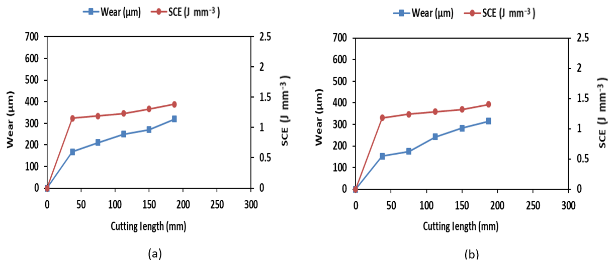
Figure 9Variation in the SCE with the increase in the tool wear at different cutting lengths for (moderate wear region conditions); (a) Condition 3 (V=130 m min−1, f=0.12 mm per rev), (b) Condition 8 (V=62.5 m min−1, f=0.16 mm per rev).
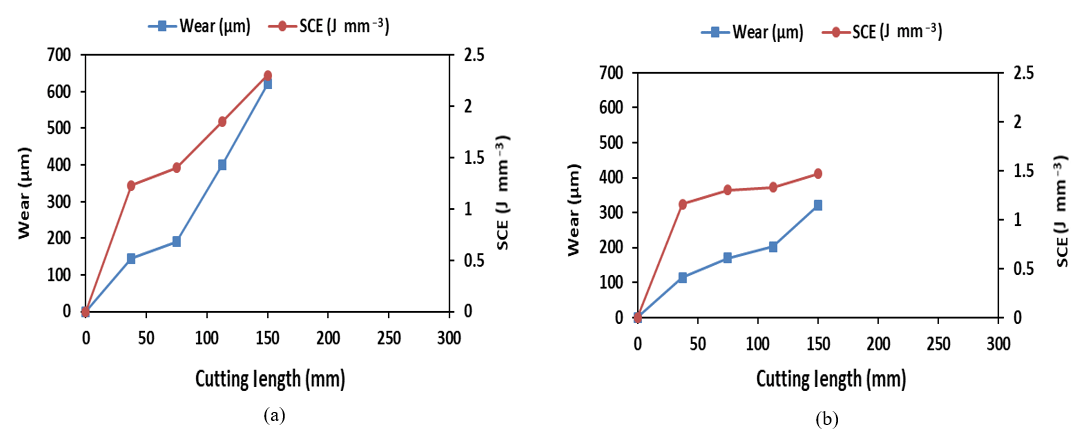
Figure 10Variation in the SCE with the increase in the tool wear at different cutting lengths for (high wear region conditions); (a) Condition 1 (V=200 m min−1, f=0.12 mm per rev), (b) Condition 2 (V=125 m min−1, f=0.24 mm per rev), (c) Condition 4 (V=90 m min−1, f=0.24 mm per rev), (d) Condition 5 (V=75 m min−1, f=0.16 mm per rev).
4.2 Wear Progression analysis
For each machining condition, the tool state and wear were monitored after a specified length of cut and analyzed using an optical microscope. Similarly, the SCE was also measured for each step of the experimental condition performed. The tool flank wear progression observed for eight selected machining conditions is presented in Fig. 6, indicating the evolution of the tool flank wear progression (VB) vs. the cutting length. It was observed that the wear rate increased when the machining conditions were varied from low to high-speed conditions on the map. The machining was progressed until the wear at the tool flank side reached an average value of VB≥0.3 for each cutting condition listed in Table 2. The wear rates were high for all those conditions at which the combination of feed and speed were selected from high wear zone on the map, as it can be seen for condition 1, 2, 4 and 5. Whereas, condition 6 and 7, selected from lower wear region of the map, a low wear rate can be observed. SEM images of the tool wear progression in Table 3, confirms the increase in the wear as the length of cut is varied. A fresh insert was used for each specified length of cut. Tool chipping was observed for condition 1 (V=200 m min−1, f=0.12 mm per rev) when it was used beyond 150 mm length of cut.
4.3 Influence of tool wear on SCE
The progressive tool wear was analyzed for all conditions by considering the variation in progressive SCE in dry turning Ti-6Al-4V alloy. The results for the tool wear progression for the condition in low wear zone (low speed) was observed to produce less variation in the SCE. At low speed and feed rates, the MRR is low which results in less worn out tool and thus produces little variation in the SCE consumed as shown in Fig. 7a, b. In case of uncoated carbide tools at low cutting speed, a layer of adhesive material is formed on the tool face which protects it from wear out (Fan et al., 2016). This is also confirmed by the SEM image of the tool when used for low-speed cutting Fig. 8.
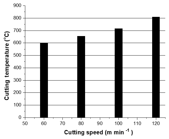
Figure 11Temperature variation with increasing the cutting speeds (Fan et al., 2016).
Figure 9a, b the conditions were selected from moderate wear zone and thus cutting operations resulted in moderate progression of the flank wear. However, the change in the SCE values was noticeable which could be attributed to the higher wear rate due to adhesion wear. The wear and SCE in condition 8 show a high values as the feed rate is higher than condition 3.
The change in the wear and SCE resulted from cutting conditions in the high tool wear zone (high-speed range) are presented in Fig. 10a–d. Condition 1 and 2 show the highest rate for both wear and energy among the selected conditions this is because of shear localization and strong adhesion of the material near edge resulting in localized temperature zone at high speed (Dudzinski et al., 2002). This increase in flank wear during cutting with an increase in velocity and feed has overly been reported by earlier researchers (Venugopal et al., 2007b; Kaplan et al., 2018). The higher wear rate and hence the variation in SCE in condition 2 (V=125 m min−1, f=0.24) is also because of the higher feed rate that produces significant temperature at the tool work piece interface (Bermingham et al., 2011; Li and Liang, 2006). As can be seen from Fig. 10a the SCE increased from 1.36 (value taken when average flank wear 0.3 is reached) to 2.31 (when maximum wear is reached) resulting 69 % increase in the SCE value because the wear progression trend sharply increases in thehigh-speed conditions.
When the speed is high the tool is subjected to high thermal stresses which result in poor cutting performance of the cutting edge. The increase in temperature with cutting speed is shown in Fig. 11 (adopted from Fan et al., 2016).
4.4 Influence of cutting speed on wear and SCE
The wear progression and SCE with machining time at two cutting condition are shown in Fig. 12. The tool life observed is significantly high in Condition 6 (V=50 m min−1, f=0.12 mm per rev) as compared to Condition 1 (V=200 m/min, f=0.12 mm min−1). With increasing the cutting time, for Condition 1, the average flank wear of the tool accelerated rapidly and resulted in very high SCE. This shows that at higher cutting speed the tool life reduces drastically resulting in higher SCE. Thus tool life can be significantly improved when using the appropriate cutting condition for machining titanium. The result also shows that variation in the SCE is due to the cutting conditions selected from different zones, thereby, conditions from the map must be carefully selected to promote economic production.
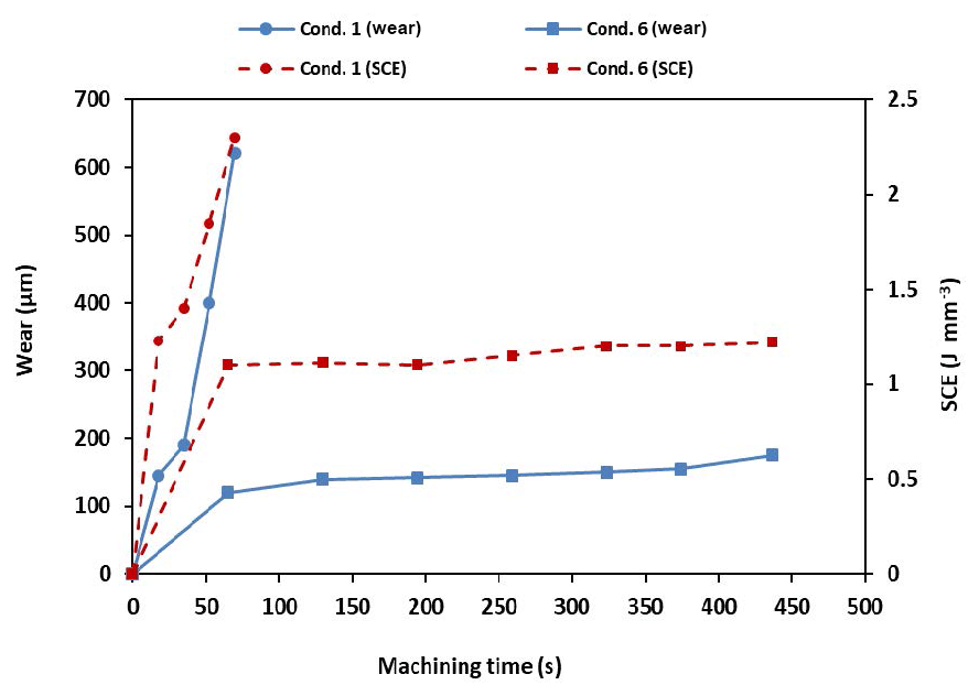
Figure 12The variation in flank wear and SCE with an increase in cutting speed (Cond. 1 and Cond. 6).
The SCE has a direct correlation with the flank wear, this can be seen from Fig. 13. There is a significant increase in the values of SCE as the wear increases beyond the acceptable limit (0.3 mm) and indicates a need to change the tool. Therefore, this work carries great importance to use SCE as a method for relating the tool wear and administering the change of tooling when needed. The tool flank wear can also be modeled in terms of SCE as shown in the Fig. 13. Using these simplified relationships machinist can predict the wear and/or SCE, thereby, optimizing the energy consumption demand during machining operations. The high-speed machining requires further investigation using the different coated tool as well as also provides the basis for the development of new tool material. There is also a case of using different cutting environments (wet, cryogenic and MQL) to study the tool wear progression and its influence on SCE.
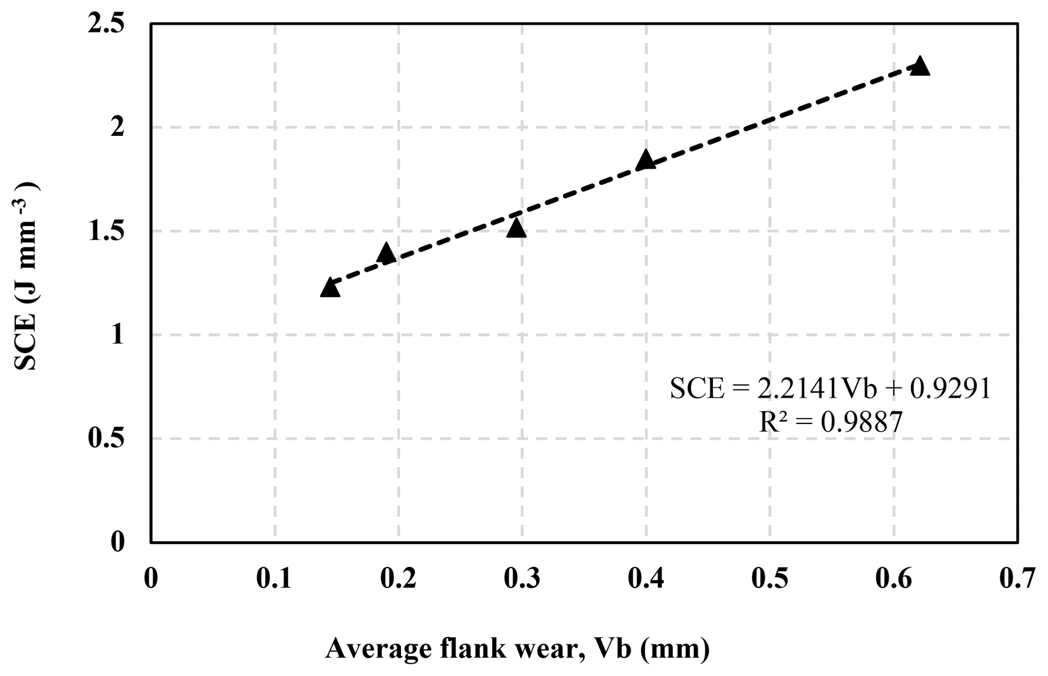
Figure 13SCE at different flank wear in turning Ti-6Al-4V; V=200 m min−1, f=0.12 mm per rev and d=1 mm.
The research work presented here relates the tool wear and the SCE at high, moderate and low wear condition. Tool wear is a major reason for the variation in SCE, as the machining process progresses. The wear is accelerated due to the increase in speed and the feed rate, noticeably reducing the life of the tool. When the cutting speed is higher, a high SCE was observed which is related to an abrupt increase in the tool flank wear because of elevated temperature at the tool and chip edge. However, for lower cutting speed the SCE was low and thus tools can be used for longer cuts that lead to higher machining time. To accomplish sustainable machining goal with efficient resources, processes must be carried out at low SCE values which will also ensure low wear of the tool at that point. Additionally, SCE and wear can be related to a machining condition using simplified relationships. The results stated here can also be used in selecting machining conditions which help to improve the tool life and in minimizing the SCE utilization in dry turning of titanium using H13 inserts. The authors are currently investigating the phenomenon of tool flank wear and energy using different coolants as the high-speed machining of such alloy must be investigated for improved results.
No data sets were used in this article.
MY and MK designed experiments, AK helped in developing methodology and graphs plotting. MY and ZK performed experiments supervised by SHIJ on the CNC machine and characterization of tools. LA and RA reviewed drafted paper, suggested amendments and guidance during revisions.
The authors declare that they have no conflict of interest.
This paper was edited by Xichun Luo and reviewed by two anonymous referees.
Arrazola, P. J., Garay, A., Iriarte, L. M., Armendia, M., Marya, S., and Le Maitre, F.: Machinability of titanium alloys (Ti6Al4V and Ti555.3), J. Mater. Process. Tech., 209, 2223–2230, https://doi.org/10.1016/j.jmatprotec.2008.06.020, 2009.
Balogun, V. A. and Mativenga, P. T.: Impact of un-deformed chip thickness on specific energy in mechanical machining processes, J. Clean. Prod., 69, 260–268, 2014.
Balogun, V. A., Gu, H., and Mativenga, P. T.: Improving the integrity of specific cutting energy coefficients for energy demand modelling, P. I. Mech. Eng. B-J. Eng., 229, 2109–2117, 2015.
Behrendt, T., Zein, A., and Min, S.: Development of an energy consumption monitoring procedure for machine tools, Cirp Ann.-Manuf. Techn., 61, 43–46, https://doi.org/10.1016/j.cirp.2012.03.103, 2012.
Bermingham, M. J., Kirsch, J., Sun, S., Palanisamy, S., and Dargusch, M. S.: New observations on tool life, cutting forces and chip morphology in cryogenic machining Ti-6Al-4V, Int. J. Mach. Tool Manu., 51, 500–511, https://doi.org/10.1016/j.ijmachtools.2011.02.009, 2011.
Deng, J. X., Li, Y. S., and Song, W. L.: Diffusion wear in dry cutting of Ti-6Al-4V with WC/Co carbide tools, Wear, 265, 1776–1783, https://doi.org/10.1016/j.wear.2008.04.024, 2008.
Dudzinski, D., Molinari, A., and Schulz, H.: Metal cutting and high speed machining, Kluwer Academic, New York, xi, 490 pp., 2002.
Ezugwu, E. O., Bonney, J., and Yamane, Y.: An overview of the machinability of aeroengine alloys, J Mater Process Tech, 134, 233–253, https://doi.org/10.1016/S0924-0136(02)01042-7, 2003.
Fan, Y. H., Hao, Z. P., Zheng, M. L., and Yang, S. C.: Wear characteristics of cemented carbide tool in dry-machining Ti-6Al-4V, Mach. Sci. Technol., 20, 249–261, 2016.
Gupta, M. K., Sood, P. K., Singh, G., and Sharma, V. S.: Investigations of performance parameters in NFMQL assisted turning of titanium alloy using TOPSIS and particle swarm optimisation method, Int. J. Mater. Prod. Tec., 57, 299–321, https://doi.org/10.1504/Ijmpt.2018.095116, 2018.
Hughes, J. I., Sharman, A. R. C., and Ridgway, K.: The effect of cutting tool material and edge geometry on tool life and workpiece surface integrity, P. I. Mech. Eng. B-J. Eng., 220, 93–107, https://doi.org/10.1243/095440506X78192, 2006.
ISO: 3685: Tool-Life Testing with Single-Point Turning Tools, International Organization for Standardization (ISO), Geneva, Switzerland, 1993.
Jaffery, S. I. and Mativenga, P. T.: Assessment of the machinability of Ti-6Al-4V alloy using the wear map approach, Int. J. Adv. Manuf. Tech., 40, 687–696, 2009.
Jaffery, S. H. I. and Mativenga, P. T.: Wear mechanisms analysis for turning Ti-6Al-4V-towards the development of suitable tool coatings, Int. J. Adv. Manuf. Tech., 58, 479–493, https://doi.org/10.1007/s00170-011-3427-y, 2012.
Jaffery, S. H. I., Khan, M., Sheikh, N. A., and Mativenga, P.: Wear mechanism analysis in milling of Ti-6Al-4V alloy, P. I. Mech. Eng. B-J. Eng., 227, 1148–1156, https://doi.org/10.1177/0954405413481210, 2013.
Jaffery, S. H. I., Khan, M., Ali, L., and Mativenga, P. T.: Statistical analysis of process parameters in micromachining of Ti-6Al-4V alloy, P. I. Mech. Eng. B-J. Eng., 230, 1017–1034, https://doi.org/10.1177/0954405414564409, 2016.
Kaplan, B., Odelros, S., Kritikos, M., Bejjani, R., and Norgren, S.: Study of tool wear and chemical interaction during machining of Ti6Al4V, Int. J. Refract. Met. H., 72, 253–256, https://doi.org/10.1016/j.ijrmhm.2017.12.012, 2018.
Kara, S. and Li, W.: Unit process energy consumption models for material removal processes, Cirp Ann.-Manuf. Techn., 60, 37–40, 10.1016/j.cirp.2011.03.018, 2011.
Kumar, T. S., Ramanujam, R., Vignesh, M., Tamiloli, N., Sharma, N., Srivastava, S., and Patel, A.: Comparative evaluation of performances of TiAlN, AICrN, TiAlN/AlCrN coated carbide cutting tools and uncoated carbide cutting tools on turning Inconel 825 alloy using Grey Relational Analysis, Sensor Actuat. A-Phys., 279, 331–342, https://doi.org/10.1016/j.sna.2018.06.041, 2018.
Kuram, E.: The effect of monolayer TiCN-, AlTiN-, TiAlN-and two layers TiCN plus TiN- and AlTiN plus TiN-coated cutting tools on tool wear, cutting force, surface roughness and chip morphology during high-speed milling of Ti6Al4V titanium alloy, P. I. Mech. Eng. B-J. Eng., 232, 1273–1286, https://doi.org/10.1177/0954405416666905, 2018.
Li, A., Zhao, J., Luo, H., Pei, Z., and Wang, Z.: Progressive tool failure in high-speed dry milling of Ti-6Al-4V alloy with coated carbide tools, Int. J. Adv. Manuf. Tech., 58, 465–478, https://doi.org/10.1007/s00170-011-3408-1, 2012.
Li, G. X., Yi, S., Wen, C. E., and Ding, S. L.: Wear Mechanism and Modeling of Tribological Behavior of Polycrystalline Diamond Tools When Cutting Ti6Al4V, J. Manuf. Sci. E.-T. ASME, 140, 121011, https://doi.org/10.1115/1.4041327, 2018a.
Li, G. X., Li, N., Wen, C. E., and Ding, S. L.: Investigation and modeling of flank wear process of different PCD tools in cutting titanium alloy Ti6Al4V, Int. J. Adv. Manuf. Tech., 95, 719–733, https://doi.org/10.1007/s00170-017-1222-0, 2018b.
Li, K. M. and Liang, S. Y.: Modeling of cutting temperature in near dry machining, J. Manuf. Sci. E.-T. ASME, 128, 416–424, https://doi.org/10.1115/1.2162907, 2006.
Li, W. and Kara, S.: An empirical model for predicting energy consumption of manufacturing processes: a case of turning process, P. I. Mech. Eng. B-J. Eng., 225, 1636–1646, 2011.
Mativenga, P. T., Rajemi, M. F., and Hinduja, S.: Calculation of optimum cutting parameters based on minimum energy footprint, Cirp Ann.-Manuf. Techn., 60, 149–152, https://doi.org/10.1016/j.cirp.2011.03.088, 2011.
Revuru, R. S., Zhang, J. Z., Posinasetti, N. R., and Kidd, T.: Optimization of titanium alloys turning operation in varied cutting fluid conditions with multiple machining performance characteristics, Int. J. Adv. Manuf. Tech., 95, 1451–1463, https://doi.org/10.1007/s00170-017-1299-5, 2018.
Sandvik: Coromant catalog, Turning tools, Sandvik, Stockholm, Sweden, 2015.
Shokrani, A., Dhokia, V., and Newman, S. T.: Energy conscious cryogenic machining of Ti-6Al-4V titanium alloy, P. I. Mech. Eng. B-J. Eng., 232, 1690–1706, https://doi.org/10.1177/0954405416668923, 2018.
Sun, J. and Guo, Y. B.: A comprehensive experimental study on surface integrity by end milling Ti-6Al-4V, J. Mater. Process. Tech., 209, 4036–4042, 2009.
Venugopal, K. A., Paul, S., and Chattopadhyay, A. B.: Tool wear in cryogenic turning of Ti-6Al-4V alloy, Cryogenics, 47, 12–18, https://doi.org/10.1016/j.cryogenics.2006.08.011, 2007a.
Venugopal, K. A., Paul, S., and Chattopadhyay, A. B.: Growth of tool wear in turning of Ti-6Al-4V alloy under cryogenic cooling, Wear, 262, 1071–1078, https://doi.org/10.1016/j.wear.2006.11.010, 2007b.
Warsi, S. S., Jaffery, S. H. I., Ahmad, R., Khan, M., Ali, L., Agha, M. H., and Akram, S.: Development of energy consumption map for orthogonal machining of Al 6061-T6 alloy, P. I. Mech. Eng. B-J. Eng., 232, 2510–2522, https://doi.org/10.1177/0954405417703424, 2018a.
Warsi, S. S., Jaffery, S. H. I., Ahmad, R., Khan, M., Agha, M. H., and Ali, L.: Development and analysis of energy consumption map for high-speed machining of Al 6061-T6 alloy, Int. J. Adv. Manuf. Tech., 96, 91–102, 2018b.
Zoya, Z. A. and Krishnamurthy, R.: The performance of CBN tools in the machining of titanium alloys, J. Mater. Process. Tech., 100, 80–86, https://doi.org/10.1016/S0924-0136(99)00464-1, 2000.