the Creative Commons Attribution 4.0 License.
the Creative Commons Attribution 4.0 License.
Displacement amplification ratio modeling of bridge-type nano-positioners with input displacement loss
Jinyin Li
Peng Yan
Jianming Li
This paper presents an improved modeling method for bridge-type mechanism by taking the input displacement loss into consideration, and establishes an amplification ratio model of bridge-type mechanism according to compliance matrix method and elastic beam theory. Moreover, the amplification ratio of the designed bridge-type nano-positioner is obtained by taking the guiding mechanism as the external load of bridge-type mechanism. Comparing with existing methods, the proposed model is more accurate, which is further verified by finite element analysis(FEA) and experimental test. The consistency of the results obtained from theoretical model, FEA and experimental testing indicates that the proposed model can accurately predict the amplification characteristics of nano-positioners, which helps the analysis and design of bridge-type nano-positioners in practical applications.
- Article
(2530 KB) - Full-text XML
- BibTeX
- EndNote
With the rapid development of nano precision motion systems in the emerging field of precision engineering (Zhang et al., 2015; Hao, 2017; Liu et al., 2016), the design and analysis of nano-positioners received extensive attentions with successful applications in micro-assembly, bio-engineering, scanning probe microscopy, and precision optical inspection. To meet the needs of high-precision applications, most nano-positioners use piezoelectric actuators as the driving component thanks to its characteristics of high stiffness, high resolution and high response speed (Zi et al., 2015; Liu et al., 2015; Ling et al., 2017). It should be pointed out that the direct output displacement of a piezoelectric actuator is about one thousandth of its own length, which usually can not meet the requirements of large working range in most cases. Amplifying mechanism is typically employed to amplify and transmit displacement, such as lever mechanism (Xing, 2015; Tang and Li, 2015; Tang et al., 2018), Scott-Russell mechanism (Tian et al., 2009), rhombic mechanism (Ling et al., 2018), bridge-type mechanism (Li and Xu, 2011; Chen et al., 2018; Clark et al., 2018). Among various amplifying mechanisms, bridge-type mechanism was widely investigated due to its characteristics of high amplification ratio, compact structure and easy processing.
To better help the mechanical design and structural optimization of bridge-type nano-positioners, researchers have proposed a variety of theoretical models on bridge-type amplification mechanism to describe the displacement amplification performance. Lobontiu and Garcia (Lobontiu and Garcia, 2003) derived the stiffness and displacement amplification model of the bridge-type mechanism based on the strain energy theory and the Cartesian second theorem, although the results are too complicated for implementations. Ma et al. (2006) considered the deformation of the hinge and derived the theoretical displacement amplification ratio of the bridge-type mechanism based on the kinematics theory and the virtual displacement theorem. Ye et al. (2011) used the full symmetry of the bridge-type mechanism to establish a quarter model of the mechanism, and used the flexibility matrix method to derive the amplification ratio formula. Qi et al. (2015) analyzed the deformation of the hinge and derived the displacement amplification model of the bridge-type mechanism based on the elastic beam theory. Kim et al. (2004) used the compliance matrix method to analyze the 3-D bridge-type mechanism. However, the above results focus on the deformation of flexure hinge, without considering the influence of the input displacement loss. In fact, it is observed that the input displacement loss does affect the amplification ratio of the bridge-type mechanism. Therefore the existing models need to be improved to fill this gap.
In this paper, a bridge-type mechanism based one-dimensional nano-positioner is studied. Based on the compliance matrix and Euler beam theory, theoretical amplification models of the bridge-type mechanism and the nano-positioner are presented by considering the input displacement loss. Meanwhile, finite element analysis (FEA) and experiments are also conducted to verify the proposed modeling method.
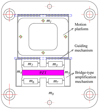
The structure of the one-dimensional bridge-type nano-positioner studied in this paper is shown in Fig. 1. It mainly includes the bridge-type amplification mechanism, the guiding mechanism and motion platform. The bridge-type amplification mechanism can amplify the output displacement of the piezoelectric stack and the guiding mechanism composed of four flexible leaf springs has a symmetrical structure. Thanks to the leaf springs with characteristics of high longitudinal stiffness, low transverse stiffness and low stress concentration, the guiding mechanism can suppress the lateral parasitic displacement.
The bridge-type mechanism is composed of the input end, the output end, the flexible hinge and the bridge-type arm, as shown in Fig. 2. The displacement amplification deformation occurs at the input end and flexible hinges. Generally speaking, the straight-beam hinges are more flexible than other types of hinges of the same size. Therefore, the straight-beam hinges are used in the bridge-type mechanism in this paper. Moreover, the output end of the bridge-type mechanism is connected with the motion platform, where the platform is guided by the guiding mechanism. It is apparent that the guiding mechanism can be considered as an external load of the bridge-type mechanism.
A piezoelectric stack actuator is installed in the middle position of the bridge mechanism and connected with the input end of the bridge-type mechanism. According to the principle of triangular amplification, the output displacement of the piezoelectric stack is enlarged by the bridge-type mechanism such that the displacement is transmitted to the motion platform.
3.1 Modeling of bridge-type mechanism

Figure 3(a) Working principle of bridge-type mechanism. (b) Influence of external load on the bridge-type mechanism.
As shown in Fig. 3a, the output force of the piezoelectric stack is applied on the input end, and the flexible hinge is deformed to achieve a large displacement output at the output end. When the piezoelectric stack moves, the input end of the bridge-type mechanism moves from points R and S to points R′ and S′, respectively, and the output end moves from point V to point V′. The input displacement of the bridge-type amplifying mechanism on one side is xin1, and the output displacement is yout1. The ideal displacement amplification is as follow:
In practice, the bridge arm at the input end inevitably deforms and affects the displacement amplification performance of the bridge-type mechanism, as shown in Fig. 3a. The input end of the bridge-type mechanism moves from points R and S to points R′′ and S′′, respectively. The input displacement on one side is
where Δin is the one-sided deformation of the input end.
From the Eqs. (1) and (2), the displacement amplification ratio of the bridge-type mechanism considering the displacement loss at the input end can be obtained as
The bridge-type mechanism will be subjected to the external load Fout of the guiding mechanism, where the output end will move from point V′ to point V′′, as shown in Fig. 3b. Considering the input displacement loss and external load, we can obtain the displacement amplification ratio of bridge-type mechanism as
where is the displacement loss under external load.
The input end of the bridge-type mechanism under the action of piezoelectric stack driving force can be simplified into a simple supported beam with an intermediate force. According to the Euler beam theory and boundary conditions, the deflection of the beams can be obtained:
where Fin is the input force, is the moment of inertia of the input end, l3, b3 and h3 are the length, width and thickness of the simply supported beam, E is the Young's modulus.
Note that the output force of the piezoelectric stack is applied to the intermediate position () of the input end, where the deformation of the simply supported beam can be regarded as the displacement loss, with
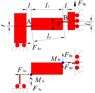
Thanks to the symmetrical structure, the model of the bridge-type amplification mechanism can be obtained by analyzing the 1/4 structure. As shown in Fig. 4, and are two pairs of reaction forces applied to the hinges A and B. The following results can be obtained from the force balance relationship:
where l1 is the length of the bridge-type arm, l2 is the vertical distance between the hinges, la is the distance between the hinges, a is the deflection angle between the two hinges.
In this study we only consider the planar deformation of the flexible hinge. Based on the compliance matrix method (Koseki et al., 2002), the straight-beam flexible hinge output can be simplified to
where Δxl and Δyl are deformations of the flexible hinge in the plane along the x and y directions respectively, Δa is the rotation angle of the flexible hinge around the z axis, E is the Young's modulus of the material, G is the shear modulus, l, t and b are the length, width and thickness of the hinge.
To further study the deformation of the bridge-type mechanism, we consider tensile deformation of the bridge arm during the amplification process
where Aa is the cross-sectional area of the bridge arm connecting the two hinges.
Input displacement of 1∕4 structure is considered in the following parts: deformation of flexible hinges A and B, rotation and extension of bridge arm AB, displacement loss at the input end, which results in
Similarly, the output displacement of 1∕4 structure is considered with the following factors: deformation of flexible hinges A and B, rotation and extension of bridge arm AB, which is represented as
Substituting Eqs. (6), (10), (11) and (12) into Eq. (13), we can obtain the input displacement as
Similarly we can obtain the output displacement by substituting Eqs. (10), (11) and (12) into Eq. (14):
When the external load is applied, the amplification ratio of the bridge-type mechanism considering the input displacement loss can be obtained as
If the external load Fy=0, the amplification ratio of the bridge-type mechanism can be written as
The above results indicate that the displacement loss at the input end reduces the effective displacement input of the bridge-type mechanism, which further affects the amplification performance. Therefore, the influence of the input end structure parameters on the amplification ratio can not be neglected for the analysis and design of bridge-type mechanism. Also note that the displacement amplification ratio of bridge-type mechanism is not dependent on the material.
Note that if we do not consider the input displacement loss (i.e. Δin=0), we can get the amplification ratio of the bridge-type mechanism as
which is different from the result considering the impact of input displacement loss as shown in Eq. (18). We will further verify this discrepancy with the FEA method in Sect. 4.
3.2 Modeling of guiding mechanism
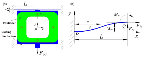
As shown in Fig. 5a, the guiding mechanism in the nano-positioner is the external load of the bridge-type amplification mechanism. In order to deliver large displacement while reducing parasitic displacement in x direction, the guiding mechanism employs four long flexible leaf springs of the same size, with a symmetrical arrangement.
The long flexible leaf spring can be treated as a tension spring, as shown in Fig. 5b. The end point is subjected to load . Since the deformation range of the nano-positioner is much smaller than the size of the long flexible leaf spring, the effect of tensile force Fnq on the rotation and deflection can be neglected, where the rotation angles produced by Fsq and Mq are
The deflections induced by Fsq and Mq are
where is the moment of inertia of the flexible leaf spring, ts, bs, ls are the thickness, width and length of the leaf spring respectively.
Now that recall the boundary conditions that wp=0, θp=0, and θq=0. The deflection of single leaf spring can be obtained by superposition from Eqs. (20) and (21):
The stiffness of guiding mechanism is
where sy is the output displacement of the guiding mechanism under the force Fout and k1 is the stiffness of a single flexible leaf spring.
3.3 Modeling of the nano-positioner
According to the symmetry of the bridge-type mechanism, the input and output displacements are
From Eqs. (7), (8), (9), (11), (16), (23) and (25), the output displacement of the bridge-type nano-positioner can be derived as
In summary, the amplification ratio of the nano-positioner is
where
To verify the model proposed in this paper, FEA simulations will be provided in this section. The material of the nano-positioner is aluminum alloy Al-7075.
4.1 Finite element verification of the bridge-type mechanism
We first conduct simulations of the bridge-type mechanism without externalload, where the structure parameters are shown in Table 1.
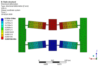
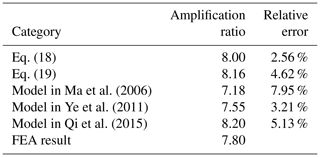
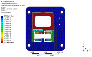
The case of 20 µm of input displacement is depicted in Fig. 6, where the displacement amplification ratio of the bridge-type mechanism is also obtained and compared with existing results in the literature, as shown in Table 2. It is clearly seen that the model proposed in the present work can more accurately describe the mechanism amplification ratio of the bridge-type mechanism, compared with representative results such as Ma et al. (2006); Ye et al. (2011) and Qi et al. (2015), thanks to the consideration of the input displacement loss. The importance of considering the input displacement loss can also be seen from the comparison of Eqs. (18) and (19) in Table 2.
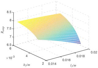
Ma et al. (2006)Ye et al. (2011)Qi et al. (2015)It is also interesting to check the influence of the input structure parameters (l3, h3) on the amplification ratio of the bridge-type mechanism, which is shown in Fig. 7 by recalling Eq. (18).
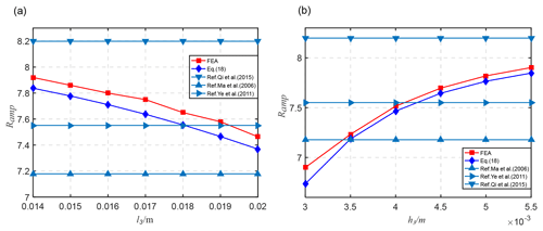
Figure 8Influence of structure parameters on amplification ratio. (a) The influence of l3 on the amplification ratio. (b) The influence of h3 on the amplification ratio.
In order to verify the influence of the input end displacement loss on the amplification performance of the mechanism, the displacement amplification under different structural parameters (l3, h3) was simulated. The analysis results are shown in Fig. 8, which shows the necessity of considering the input displacement loss in the modeling of the bridge-type mechanism. As the length l3 of the input end increases, the displacement loss of the input end of the bridge-type mechanism increases and the displacement amplification ratio decreases. As the thickness h3 of the input end increases, the input end loss of the bridge-type mechanism is reduced and the displacement amplification ratio is increased. The consistency between the simulation results and the calculation results further validates the effectiveness of the proposed modeling method.
4.2 Finite element verification of bridge-type nano-positioner
The FEA simulations are also conducted to verify the amplification ratio model of the nano-positioner as described by Eq. (27), where the structural parameters are listed in Table 3. As depicted in Fig. 9, the deformation result of the bridge-type nano-positioner with an input displacement of 10 µm is simulated. It is also seen from Table 4 that the result of Eq. (27) agrees well with that of FEA, where the relative error is only 4.16 %.
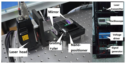
The proposed modeling method and the simulation results are also verified by experiments, where the nano-positioner is machined by the wire-cutting machining method according to the structural parameters in Table 3. The overall experimental apparatus is shown in Fig. 10, where the nano-positioner is driven by NAC14 piezoelectric stack though a high bandwidth voltage amplifier.
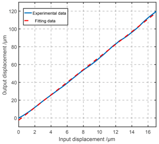
In the experiment, the slope voltage signal of 0–50 V is applied to the PZT actuator, where the input and output displacement of the nano-positioner are captured by an laser interferometer and plotted in Fig. 11. According to the experimental results, the actual displacement amplification ratio of the nano-positioner is 7.10, which is close to the calculated result of 7.26 and FEA simulation result of 6.97. As shown in Table 5, the proposed model can effectively predict the amplification performance of the bridge-type nano-positioner by considering the impact of input end displacement loss.
In this paper, an improved model was developed to describe the displacement amplification of the bridge-type mechanism, by considering the displacement loss of the input end, which was also extended to the analysis of displacement amplification ratio of bridge-type nano-positioner by regarding the guiding mechanism as the external load of the bridge-type mechanism. FEA simulations and real time experiments were provided to comprehensively evaluate the proposed method. Comparative studies and experiments indicate that the proposed method can better capture the amplification performance for such systems, which can be potentially used in the design and optimization of bridge-type nano-positioners.
All the data used in this manuscript can be obtained by requesting from the corresponding author.
The authors declare that they have no conflict of interest.
We would like to thank the National Natural Science Foundation of China, the National Key Research and Development Program of China, the Science and Technology Projects of Suzhou City, and the Key Research and Development Program of Shandong Province.
This research has been supported by the the National Natural Science Foundation of China (grant no. 51775319), the the National Key Research and Development Program of China (grant no. 2017YFF0105903), the the Science and Technology Projects of Suzhou City (grant no. SYG201718), and the the Key Research and Development Program of Shandong Province (grant no. 2018GGX103009).
This paper was edited by Guimin Chen and reviewed by Tang Hui, Zhi-Jun Yang, and one anonymous referee.
Chen, W., Lu, Q., Kong, C., Zhang, Y., and Zhang, Q.: Design, analysis and validation of the bridge-type displacement amplification mechanism with circular-axis leaf-type flexure hinges for micro-grasping system, Microsystem Technologies, Springer Berlin Heidelberg, 1–8, https://doi.org/10.1007/s00542-018-4064-2, 2018. a
Clark, L., Shirinzadeh, B., Pinskier, J., Tian, Y., and Zhang, D.: Topology optimisation of bridge input structures with maximal amplification for design of flexure mechanisms, Mech. Mach. Theory, 122, 113–131, 2018. a
Hao, G.: A Multiaxis, Large-Output, Sensing Framework of Integrating Linear Optical Encoders for Nanopositioning Systems, IEEE Sensors Letters, 1,1–4, 2017. a
Kim, J. H., Kim, S. H., and Kwak, Y. K.: Development and optimization of 3-D bridge-type hinge mechanisms, Sensor Actuat. A-Phys., 116, 530–538, 2004. a
Koseki, Y., Tanikawa, T., Koyachi, N., and Arai, T.: Kinematic analysis of a translational 3-dof micro-parallel mechanism using the matrix method, Adv. Robotics, 16, 251–264, 2002. a
Li, Y. and Xu, Q.: A totally decoupled piezo-driven XYZ flexure parallel micropositioning stage for micro/nanomanipulation, IEEE T. Autom. Sci. Eng., 8, 265–279, 2011. a
Ling, M., Cao, J., Zhou, J., and Jing, L.: Modular kinematics and statics modeling for precision positioning stage, Mech. Mach. Theory, 107, 274–282, 2017. a
Ling, M., Cao, J., Zhou, J., Zeng, M., and Li, Q.: Optimal design of a piezo-actuated 2-DOF millimeter-range monolithic flexure mechanism with a pseudo-static model, Mech. Syst. Signal Pr., 115, 120–131, 2018. a
Liu, P., Yan, P., and Zhang, Z.: Design and analysis of an X-Y parallel nanopositioner supporting large-stroke servomechanism, P. I. Mech. Eng. C-J. Mec., 229, 364–376, 2015. a
Liu, Y., Zhang, Y., and Xu, Q.: Design and Control of a Novel Compliant Constant-Force Gripper Based on Buckled Fixed-Guided Beams, IEEE/ASME Transactions on Mechatronics, 476–486, 2016. a
Lobontiu, N. and Garcia, E.: Analytical model of displacement amplification and stiffness optimization for a class of flexure-based compliant mechanisms, Comput. Struct., 81, 2797–2810, 2003. a
Ma, H., Yao, S., Wang, L., and Zhong, Z.: Analysis of the displacement amplification ratio of bridge-type flexure hinge, Sensor Actuat. A-Phys., 132, 730–736, 2006. a, b, c
Qi, K., Xiang, Y., Fang, C., Zhang, Y., and Yu, C.: Analysis of the displacement amplification ratio of bridge-type mechanism, Mech. Mach. Theory, 87, 45–56, 2015. a, b, c
Tang, H. and Li, Y.: A new flexure-based Yθ nanomanipulator with nanometer-scale resolution and millimeter-scale workspace, IEEE-ASME T. Mech., 20, 1320–1330, 2015. a
Tang, H., Gao, J., Chen, X., Yu, K.-M., To, S., He, Y., Chen, X., Zeng, Z., He, S., Chen, C., and Li, Y.: Development and repetitive-compensated PID control of a nanopositioning stage with large-stroke and decoupling property, IEEE T. Ind. Electron., 65, 3995–4005, 2018. a
Tian, Y., Shirinzadeh, B., Zhang, D., and Alici, G.: Development and dynamic modelling of a flexure-based Scott–Russell mechanism fornano-manipulation, Mech. Syst. Signal Pr., 23, 957–978, 2009. a
Xing, Q.: Design of asymmetric flexible micro-gripper mechanism based on flexure hinges, Advances in Mechanical Engineering, 7, 1–8, https://doi.org/10.1177/1687814015590331, 2015. a
Ye, G., Li, W., Wang, Y., Yang, X., and Yu, L.: Analysis on displacement amplification ratio of a flexible bridge-type micro-displacement mechanism, The 2010 IEEE International Conference on Information and Automation, Harbin, China 20–23 June 2010, 251–256, 2011. a, b, c
Zhang, J., Suzuki, N., Wang, Y., and Shamoto, E.: Ultra-precision nano-structure fabrication by amplitude control sculpturing method in elliptical vibration cutting, Precis. Eng., 39, 86–99, 2015. a
Zi, Y., Lin, L., Wang, J., Wang, S., Chen, J., Fan, X., Yang, P., Yi, F., and Wang, Z. L.: Triboelectric-pyroelectric-piezoelectric hybrid cell for high-efficiency energy-harvesting and self-powered sensing, Adv. Mater., 27, 2340–2347, 2015. a


