the Creative Commons Attribution 4.0 License.
the Creative Commons Attribution 4.0 License.
 | 31 Jan 2018
A self-adjusting stiffness center design for large stroke compliant XY nanomanipulators
Zhiqing Liu
Zhen Zhang
Peng Yan
In the present paper, it is proposed a self-adjusting stiffness center (SASC) design for large stroke XY beam flexure-based mechanisms. An important feature of the SASC lies in it restricts the in-plane parasitic rotation by reducing the moment of force instead of increasing the rotational stiffness widely utilized in the literature. Specifically, it is shown that by leveraging on the varied stiffness of the parallelogram flexure, the stiffness center can be made stationary by appropriately setting the relevant geometric parameters, so that the parasitic rotation can be restricted. Furthermore, it is presented a millimeter stroke XY nanomanipulator with the SASC-based redundant constraint in a case study. Numerous finite element analysis (FEA) results demonstrate that the proposed design is not only capable of achieving 1.5 × 1.5 mm2 working range in a compact desktop size, but significantly reduces the in-plane moment applied to the motion stage. The proposed SASC-based design provides an alternative approach to reduce the parasitic rotation of large stroke XY beam flexure-based mechanisms.
- Article
(4547 KB) - Full-text XML
- BibTeX
- EndNote


Recently, considerable research efforts have been devoted to achieving compact large range multi-axis compliant nanomanipulators (Awtar and Parmar, 2013; Chen and Bai, 2016; Shang et al., 2015). Among these studies, the designs of beam flexure-based mechanisms with voice coil actuators (VCA) are widely adopted to show the potentials of achieving millimeters or even centimeters strokes (Howell et al., 2013; Xu, 2014).
As the stroke increases, the in-plane parasitic motions increase as well, which includes translational and rotational motions, and both of them can significantly affect nanometric motion quality of XY nanomanipulators.
More recently, some important results were reported on reducing parasitic motions of large stroke XY nanomanipulators, for example, the improved 4-PP structures with subchains connected (Yu et al., 2015), the connection bars (Hao and Yu, 2016), and the cross bars (Zhang et al., 2017). Those designs can improve some performance such as a higher degree of cross-axis decoupling and a smaller in-plane parasitic rotation. In addition, with 4-PP-E (P denotes a prismatic joint and E denotes a planar joint) structures, the in-plane parasitic rotation can be restricted by increasing the rotational stiffness (Hao and Kong, 2012; Zhang et al., 2016). Since the in-plane parasitic rotation is dependant of the in-plane rotational stiffness and moment, the parasitic rotation can be restricted by increasing the rotational stiffness and decreasing the moment. Note that the increase of rotational stiffness will increase the stiffness of the motion axis and hence restricts the stroke, which is undesired. For this reason, we in this paper propose a novel design method to restrict the parasitic rotation by means of reducing in-plane moment, but without increasing rotational stiffness. As a matter of fact, a moment occurs when the applied force does not pass through the stiffness center. Also the nonlinear stiffness of flexure mechanisms makes the thrust force do not pass through the stiffness center when the mechanism is in motion. The problem is more severe when the stroke gets larger. In order to make the thrust force always pass through the stiffness center, we propose a novel design, by which the stiffness center can be self adjusted to the ideal position when the mechanism is in operation.
Note that the transverse stiffness of the parallelogram flexure is dependent of the axial force (Awtar et al., 2007; Zhao et al., 2017). Although the transverse stiffness is nonlinear, the nonlinear stiffness can be leveraged to adjust the stiffness center. In other words, if the variation of the parallelogram flexure stiffness is known, then the position of the stiffness center can be predicted accordingly. In particular, we provide a conceptual design of an XY compliant nanomanipulator. Then by appropriately setting a set of the parameters of parallelogram flexure, we show that a self-adjusting stiffness center (SASC) design can make the stiffness center stationary, while the thrust force passing through the stiffness center all the time.
The rest of the paper is organized as follows: in Sect. 2, the SASC design method is proposed. In Sect. 3, a conceptual design of an XY nanomnipulator with SASC is provided in details. In Sect. 4, a case study is presented to realize the proposed design. In Sect. 5, numerous FEA simulations are conducted to validate the analytical results and to show the performance of the conceptual design, followed by conclusion.
To begin with, we consider the transverse stiffness of the parallelogram and double parallelogram flexure modules.
2.1 Analysis of transverse stiffness of symmetric flexure mechanism
It is known from Awtar et al. (2007) that the transverse stiffness of a parallelogram flexure KPt and double parallelogram flexure KDPt admit the following closed-forms:
where E is the modulus of elasticity, and I is the moment of inertia, and L is the length of a beam, and P is the axial force.
The axial force P on the a mirror symmetric flexure mechanism is shown in Fig. 1, where the motion stage moves along x axis.
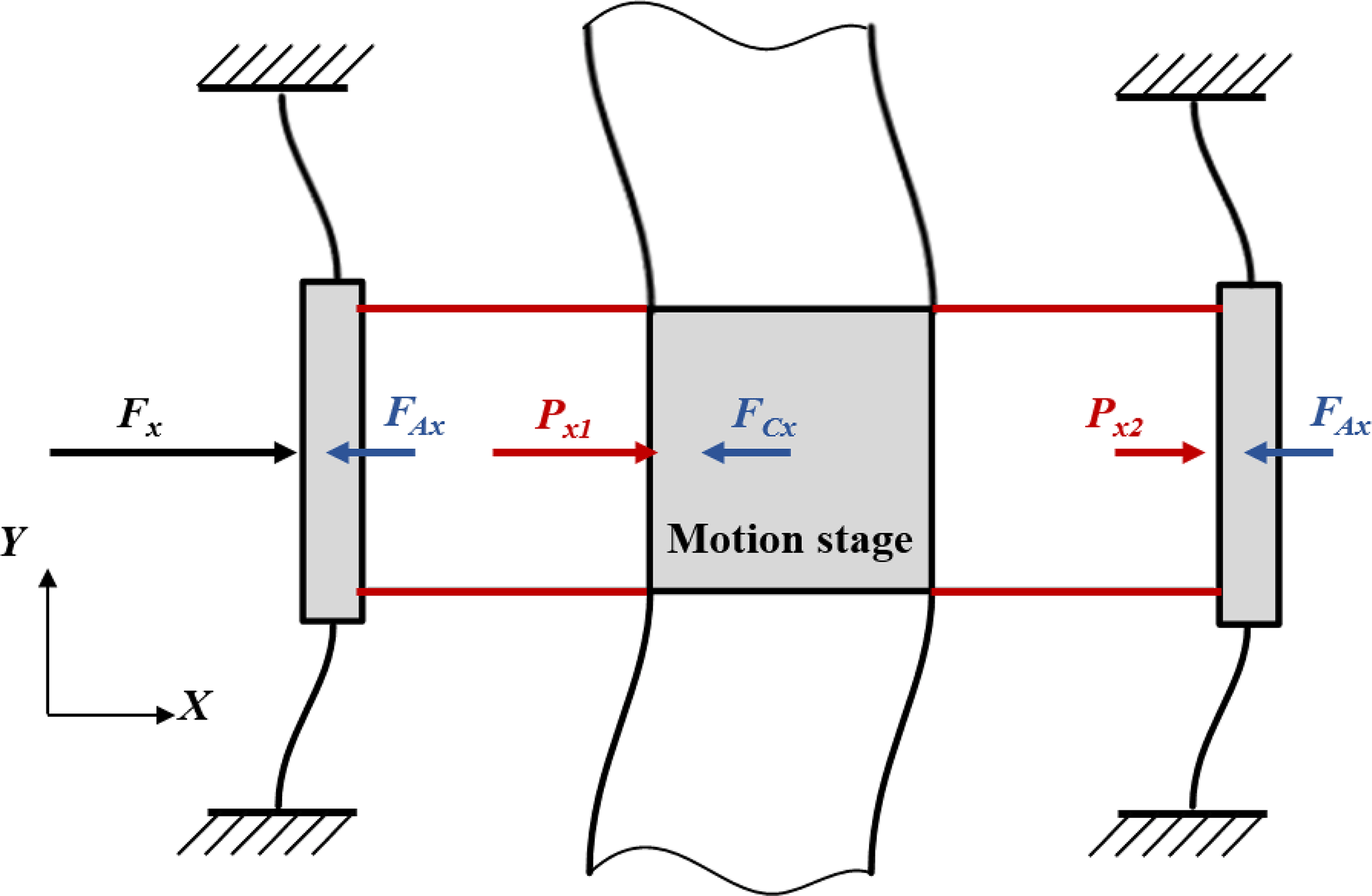
From Fig. 1, the force balance conditions can be derived by
where Fx is the applied force on x direction, and and are the axial forces on the left and right flexure mechanisms respectively, and FAx and FCx are the constrained forces of the actuation motion flexure mechanism and cross motion flexure mechanism respectively. Note that the actuation motion flexure mechanism is connected to the base, and the cross motion flexure mechanism is connected to the motion stage.
According to Eq. (2), it is seen that the axial forces on the flexure mechanism on both sides of motion stage are different when the stage is in motion, and the difference between forces and reads as
As a result, the stiffness center moves when the stage is in motion. In order to make the thrust force pass through the stiffness center when the stage is in motion, there is a need to know the position of the stiffness center which will be discussed in the following subsection.
2.2 Position of stiffness center
When the applied force goes through the stiffness center, there is no moment of force, and hence the motion stage only has a translational motion but no rotational one as shown in Fig. 2a, where the stiffness center of the mirror symmetric flexure mechanism coincides with the centroid of the motion stage. A similar illustration is referred to Hao (2014).

In contrast, when the transverse stiffness of the two flexure mechanisms on both sides of the motion stage is different, the stiffness center will no longer coincide with the centroid of the motion stage as shown in Fig. 2b. Consequently, the stiffness center moves towards to the flexure mechanism of the larger stiffness side, meanwhile the applied force does not pass through the stiffness center, which results a moment M making the motion stage rotate.
In general, one axis force analysis of a symmetric flexure mechanism can be considered as a spring-bar model as shown in Fig. 3, where O is the centroid of the bar, and C is the stiffness center of the mechanism, and A and B are the points connecting to the left and right springs, respectively, and L is the length of bar AB.
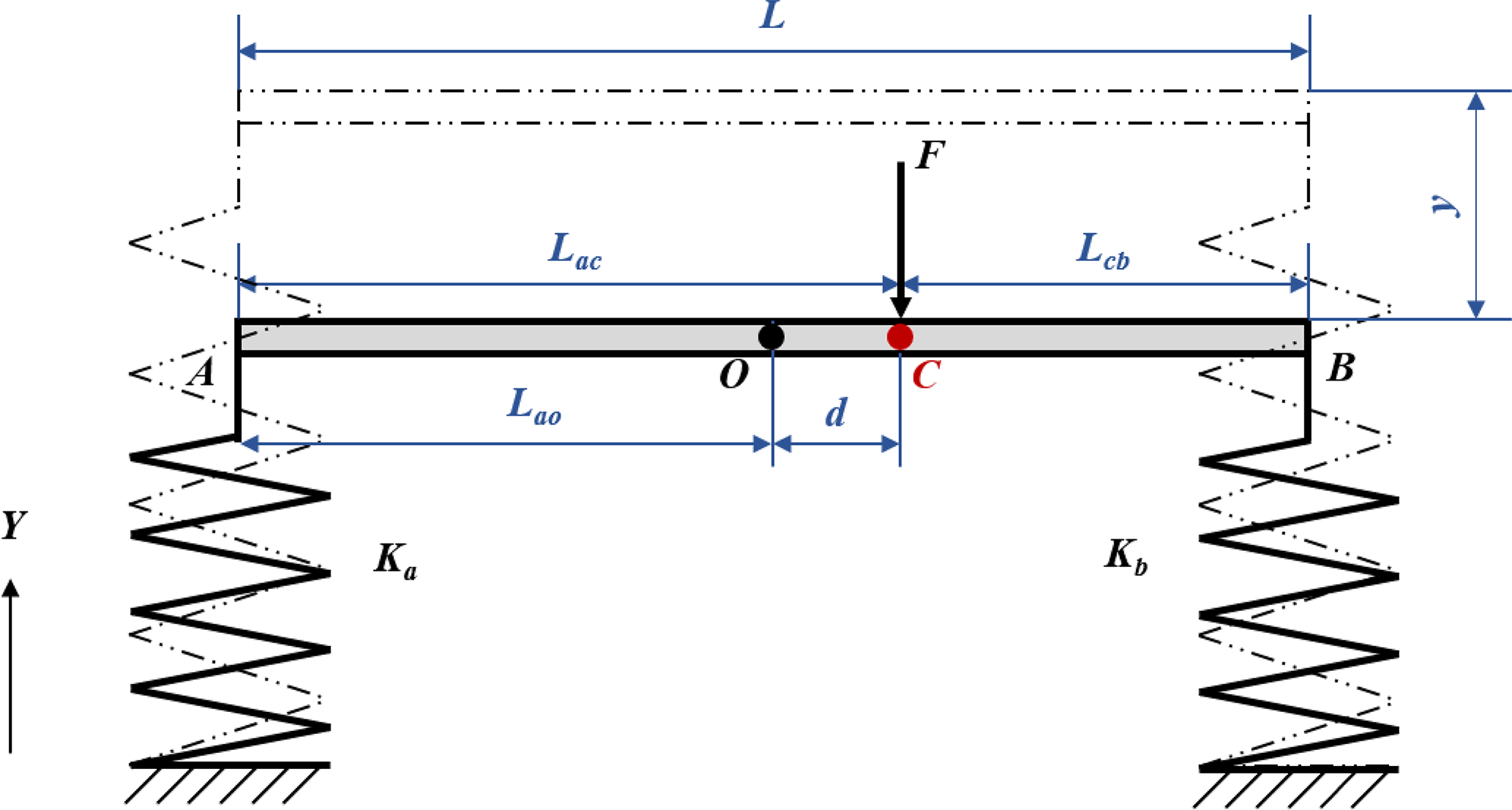
As shown in Fig. 3, the applied force F goes through the stiffness center C, which means that the bar moves translational without rotation, and the force balance conditions are derived as
where Ka, and Kb are the stiffness of the left and right springs respectively, and y is the translational motion in y direction.
From Eq. (4), the deviation of the stiffness center to the centroid O can be derived as
With the position d of the stiffness center in mind, we are in place to propose a novel design making the stiffness center stationary when the stage is in motion.
2.3 SASC design
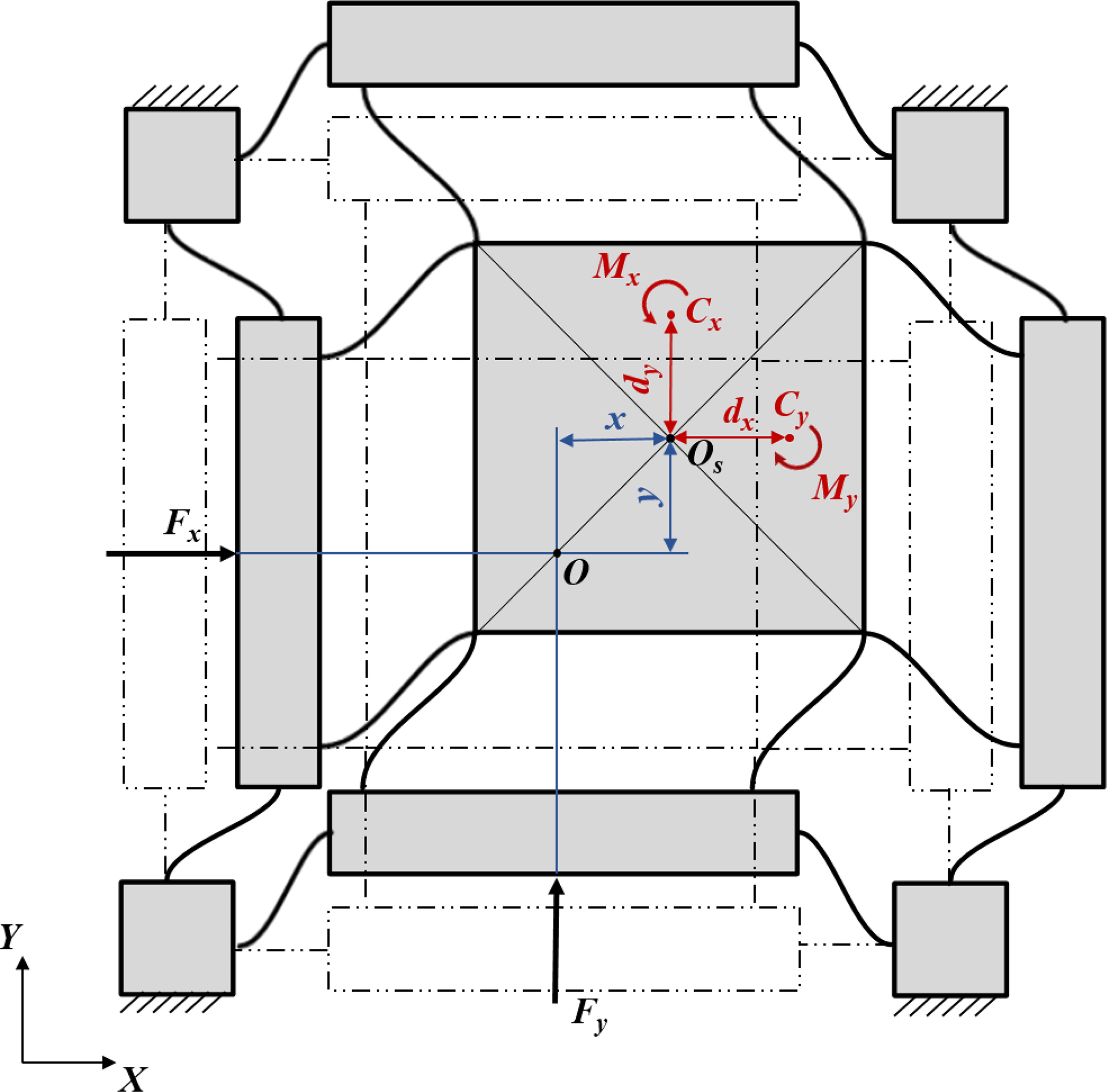
For a planar motion, the moment of force is shown in Fig. 4, where OS and O are the centroid of the motion stage and the overall system respectively; and Cx and Cy are the stiffness centers of x and y axes respectively; and Fx and Fy are the applied forces to x and y axis respectively; and x and y are the displacements of the motion stage along x and y axes respectively; and dx and dy are the deviations (Eq. 5) of stiffness centers of x and y axes respectively; and Mx and My are the moments caused by Fx and Fy respectively.
From Fig. 4, it is obtained that
which shows that the displacement of the stiffness center can be divided by two parts, that is the displacement of the motion stage x, y and the deviation dx, dy caused by different transverse stiffness.
With the above Eq. (6) in mind, if one can appropriately design the flexure mechanism such that dx and dy could compensate displacement x and y, i.e. , , then the stiffness center Cx and Cy coincide with the centroid of the overall system O, which means that the applied forces Fx and Fy always pass through the stiffness center, and hence there is no moment of force, therefore the rotational motion can be eliminated. This is the idea of the SASC design, and in what follows we apply the SASC to design a large range XY compliant nanomanipulator.
We in this section present a compliant XY nanomanipulator based on the above proposed SASC to restrict the in-plane parasitic rotation.
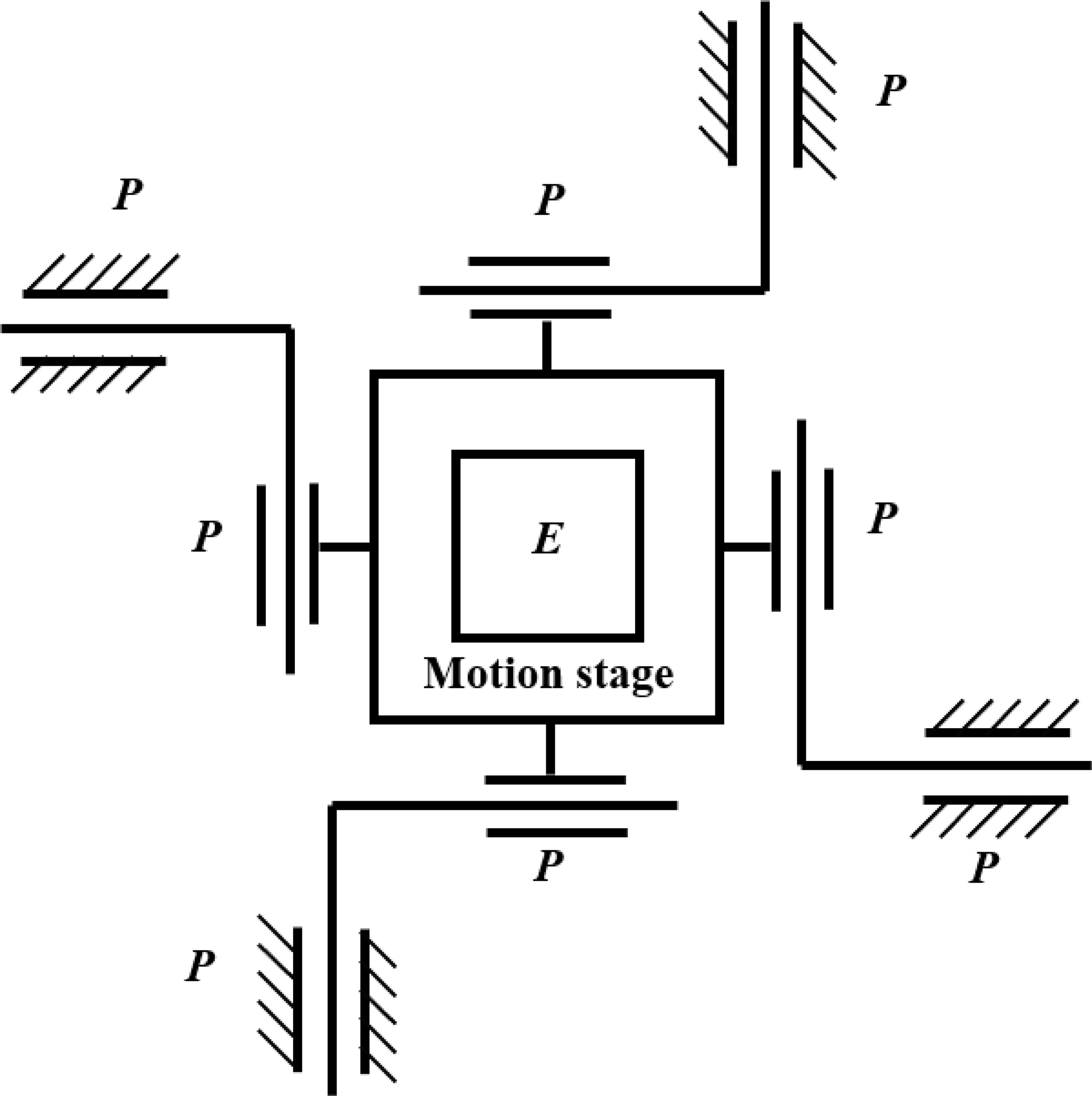
Specifically, we consider a 4-PP-E parallel mechanism (Fig. 5). The reason why we adopt such a mechanism lie in: the 4-PP can be realized by a mirror symmetric configuration, which is clearly beneficial to the improvement of planar motion accuracy; and the E joint can be designed with SASC, which significantly reduces the in-plane rotation. Then the parallelogram beam flexures are utilized to realize kinematic decoupling. Figure 6a shows the 3-D view of the conceptual design.

Figure 6A conceptual design of a compliant XY nanomanipulator. (a) 3-D view and (b) top view.
Figure 6b shows that the proposed design consists of four parts (different parts in different colors): the base, the decoupling mechanism, the SASC-based redundant constraint, and the motion stage. Since the major stiffness will be distributed to the redundant constraint to improve the motion quality, we in this study propose an SASC-based redundant constraint module, while keeping the kinematic decoupling module simple.
3.1 SASC-based redundant constraint
As the redundant constraint, the E joint is designed with the 4-PP mechanism and based on SASC. Specifically, the parallelogram and double parallelogram flexure beams are utilized for the motions on the cross actuation and actuation direction, respectively (Fig. 6b).
Since the transverse stiffness is dependent of axial forces, there is a deviation between the stiffness center and the centroid of the motion stage, moreover the deviation can be calculated according to Eq. (5). Using x axis as an illustrative example, the SASC-based redundant constraint module for x axis is shown in Fig. 7, where Lm is the side length of the motion stage; and and are the transverse stiffness of the cross motion parallelogram flexure on the left and right sides, respectively; and KAtx is the transverse stiffness of the actuation motion parallelogram flexure; and OS is the centroid of the motion stage; and C is the stiffness center of the cross motion parallelogram flexure.
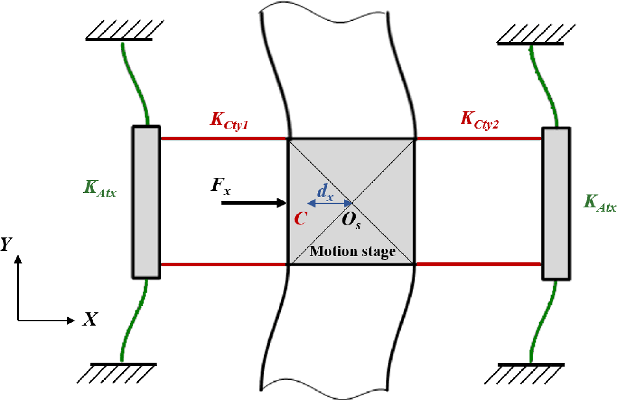
From Eq. (5), the deviation dx of the stiffness center can be expressed as
From Fig. 7, it is clear that the axial forces of the parallelogram flexure on both sides of the motion stage are of the same magnitude P but counter directions when the stage is in motion.
With this, the stiffness can be obtained as
where LA and LC are the length of the beam in actuation and cross directions respectively, and P1 is the axial force acting on the actuation mechanism, and P is of the form
By some algebraic manipulation, we obtain
By neglecting the second term of Eq. (10), we obtain the following form
In general, when a force F is applied to the left side of the motion stage (Fig. 7), the transverse stiffness of the cross motion parallelogram flexure on the left side will increase, and the transverse stiffness of the cross motion parallelogram flexure on the right side will decrease. As a result, the stiffness center of the cross motion parallelogram flexure moves left w.r.t. O. If one can appropriately design the above geometric parameters such that , then the stiffness center does not move.
3.2 Decoupling mechanism
The decoupling mechanism is also based on a 4-PP mechanism. Note that P joints for the motions on the actuation and cross directions are realized by the double parallelogram flexure beams with a mirror symmetrically arrangement. The advantages of the double parallelogram flexure lie in it can achieve relatively large stroke and is of less nonlinearity compared with that of the parallelogram flexure.
3.2.1 Double parallelogram flexure with double-beam
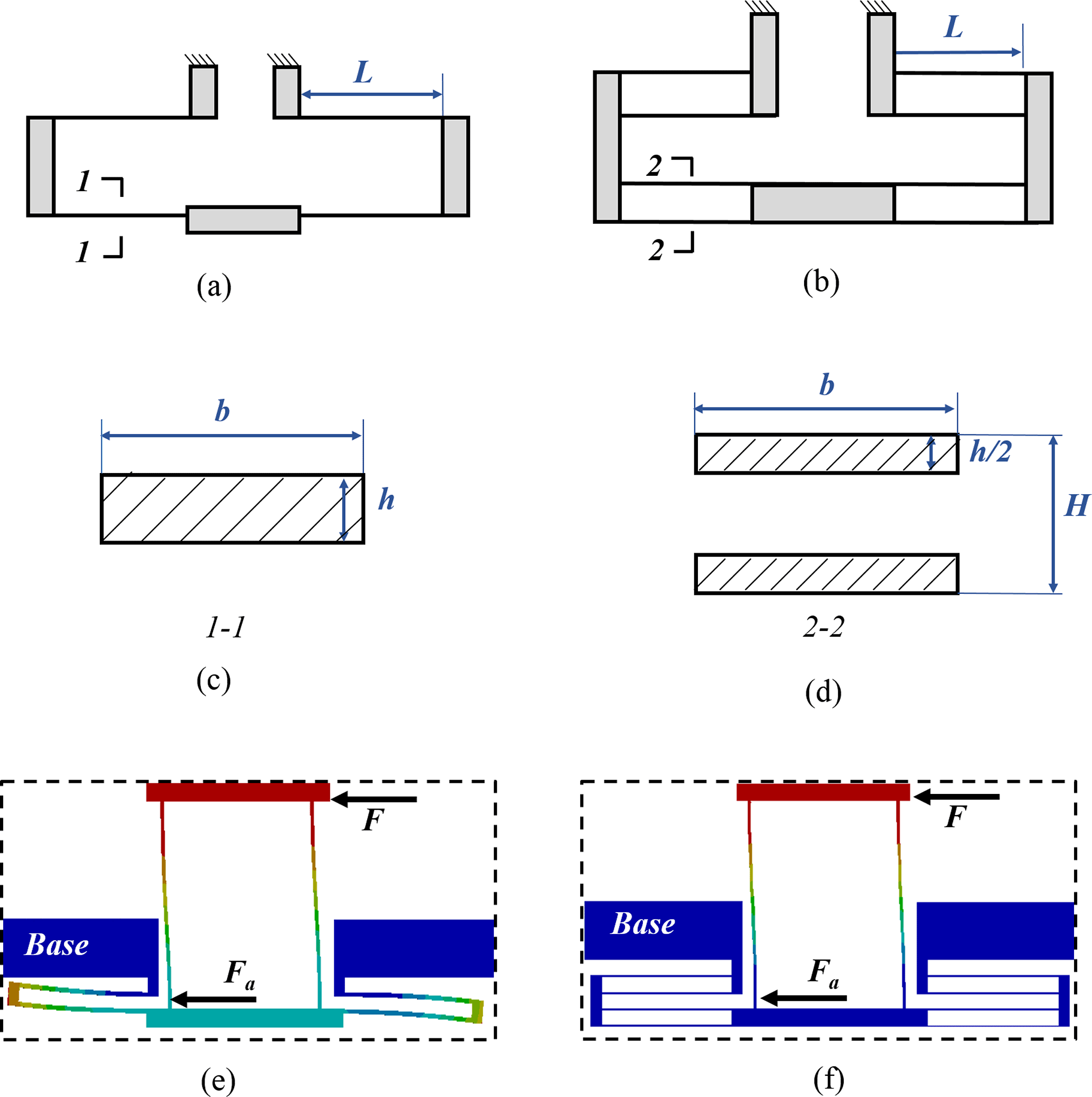
Figure 8Comparison between different beam designs. (a) double parallelogram flexure with one-beam; (b) double parallelogram flexure with double-beam; (c) cross section of one-beam; (d) cross section of double-beam; (e) FEA result with one-beam; (f) FEA result with double-beam.
The multi-beam design has been widely used in the literature, and it can significantly reduce the undesired rotation of flexure mechanisms (Awtar et al., 2010; Hao and Kong, 2012). In this conceptual design, we combine the double-beam and the double parallelogram flexure to realize the actuation motion as shown in Fig. 8, where H is the distance between two adjacent beams, and b, h and L are the width, thickness and length of the beam, respectively.
The cross section of different beams is shown in Fig. 8c–d, and it can be obtained that
where I1 and I2 are the moment of inertia of the single-beam and the double-beam, respectively.
According to Eq. (1), it is obtained that
where and are the transverse stiffness of single-beam and double-beam, respectively.
With Eqs. (12) and (13), compared with the combination of the single-beam and the double parallelogram flexure, the combination of the double-beam and the double parallelogram flexure has lager moment of inertia but smaller transverse stiffness. The FEA results are shown in Fig. 8e–f, where the above analysis is observed.
In this section, we present a design of the geometric parameters to realize the proposed SASC, and to make the overall mechanism in a compact desktop size.
4.1 Stiffness design
As shown in Fig. 6, the decoupling and the redundant constraint modules are connected in parallel. Therefore, the stiffness center of the stage depends on both of the modules. For the sake of simplicity, the SASC design is only utilized to the redundant constraint module.
To realize the SASC for the motion stage, the transverse stiffness of the cross motion flexure of the redundant constraint is designed much higher than that of the decoupling mechanism. Hence the transverse stiffness of cross motion flexure of the decoupling mechanism can be neglected. In this case, the stiffness centers of the motion stage and the redundant constraint approximately coincide with each other.
According to Eqs. (1) and (8), the stiffness models of the decoupling mechanism and redundant constraint are expressed as follows:
And the stiffness model of the whole system reads as
where KSASC, Kd and Ks are the stiffness of the redundant constraint, the decoupling mechanism and the overall mechanism, respectively; and the subscripts 1 and 2 denote the redundant constraint and the decoupling mechanism, respectively.
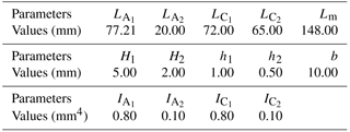
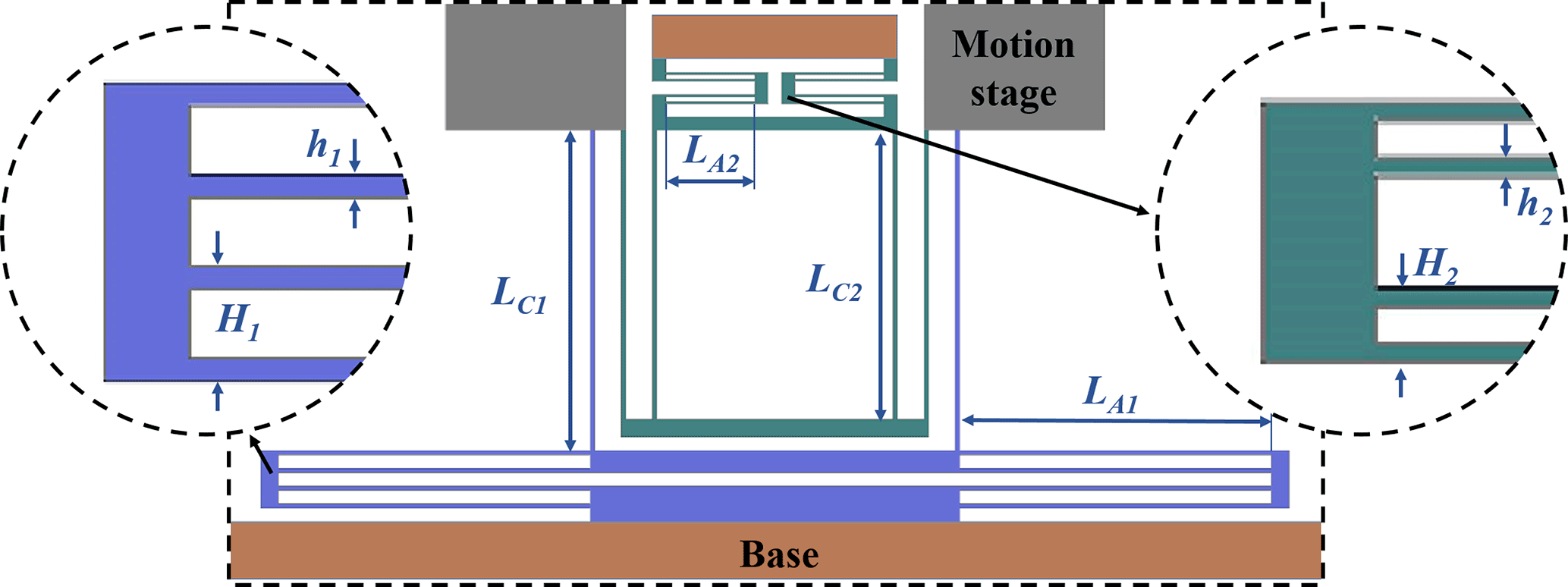
The desired stroke is 1.5 × 1.5 mm2, and stiffness Ks is designed as 60 N mm−1. According to Eqs. (10) and (15), the set of geometric parameters is shown in Fig. 9 and the designed values are given in Table 1, where LA and LC are defined in Eq. (10), and H and h are defined in Fig. 8, and the subscripts 1 and 2 denote the redundant constraint and the decoupling mechanisms, respectively.
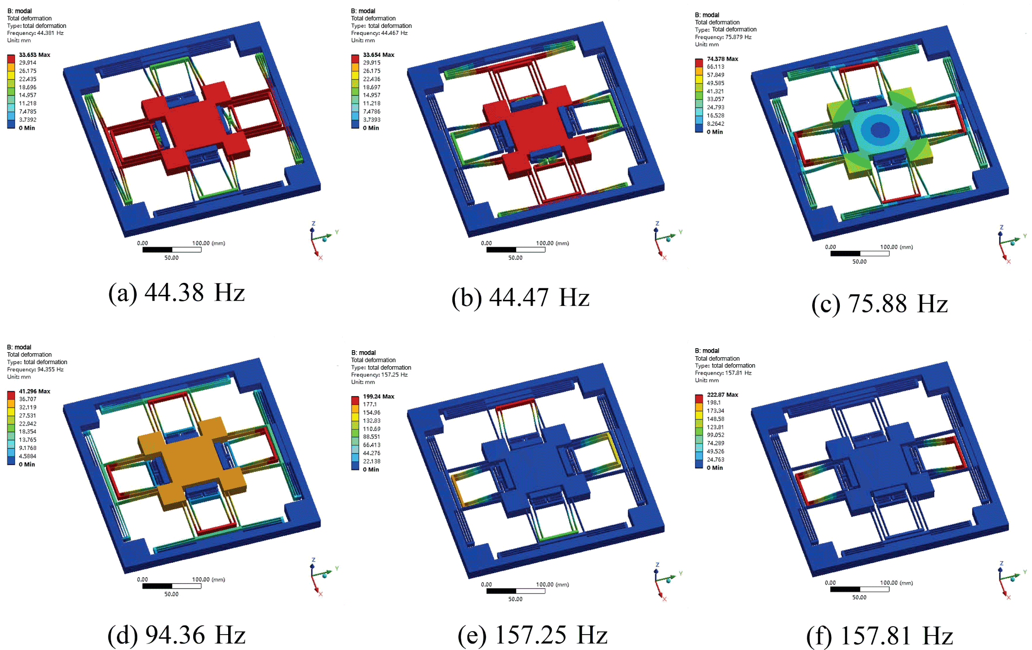
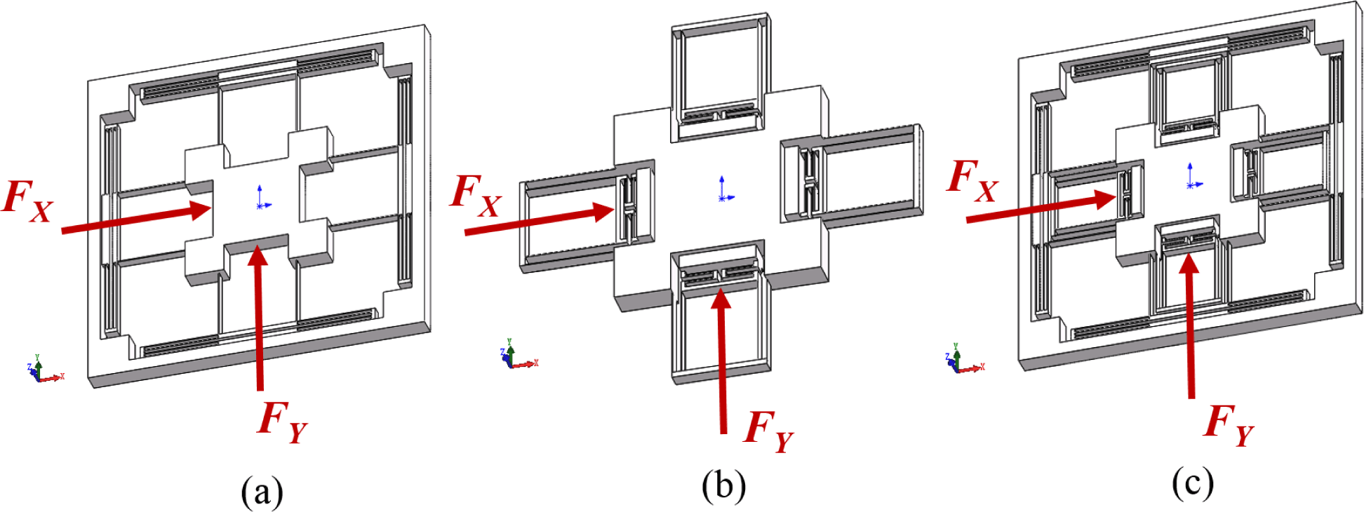
Figure 11The applied forces in the FEA (a) the redundant constraint (b) the decoupling mechanism (c) the overall stage.
With the above design, the overall dimension of the proposed XY nanomanipulator is of 300 × 300 × 40 mm3, which is in a compact desktop size.
4.2 Sensitivity analysis
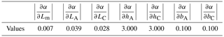
In this subsection, we conduct the sensitivity analysis of the above SASC-based design. According to Eq. (10) and Table 1, set α as
If , then the SASC is achieved. The sensitivity of the geometric parameters to α is calculated and listed in Table 2, where the thickness of the beams hA and hC have the highest sensitivity to α.
Consider the accuracy of electrical discharge machining (EDM) as 5 µm, which leads to an error to α less than 1.5 %. Therefore it is safe enough to fabricate the proposed conceptual design by means of EDM.
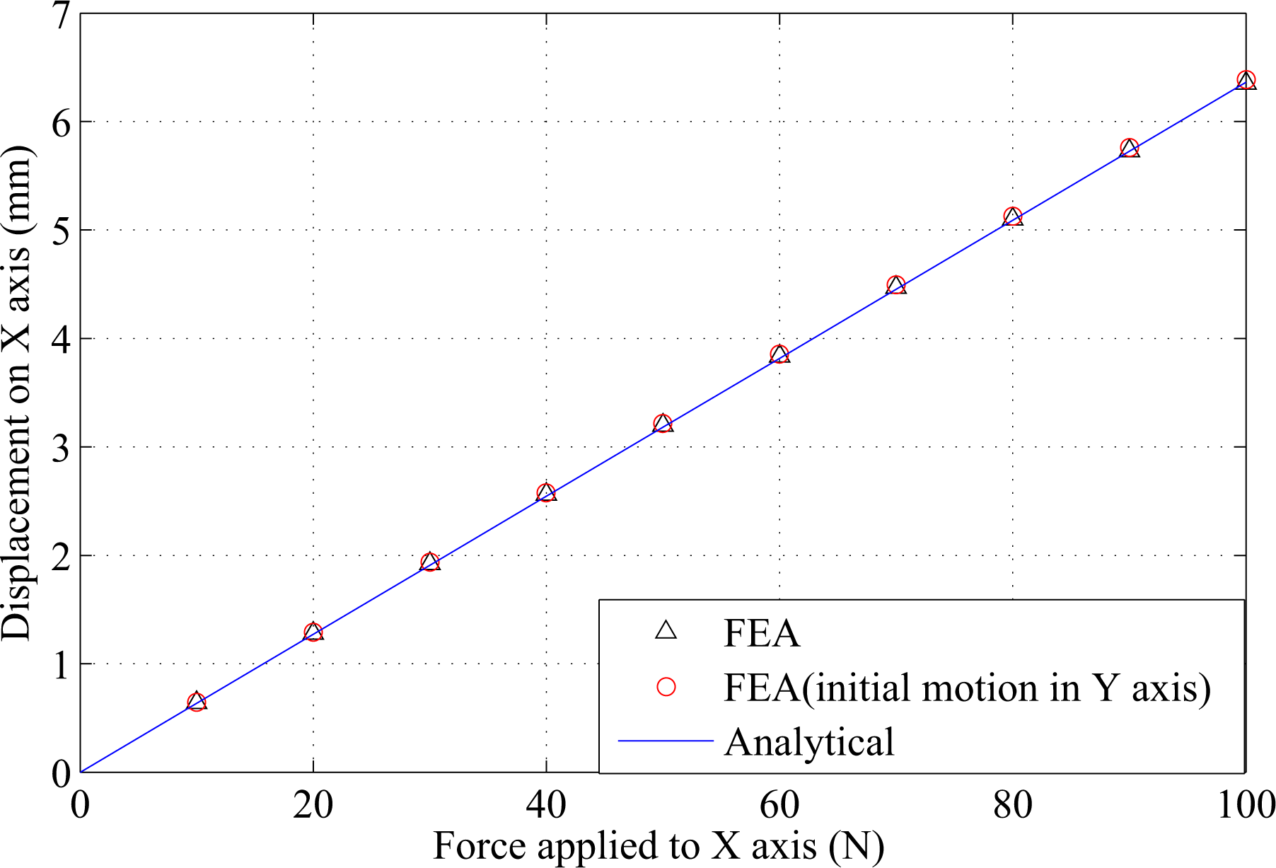
Figure 12Motion of the redundant constraint in x axis given the maximum displacement in y axis.
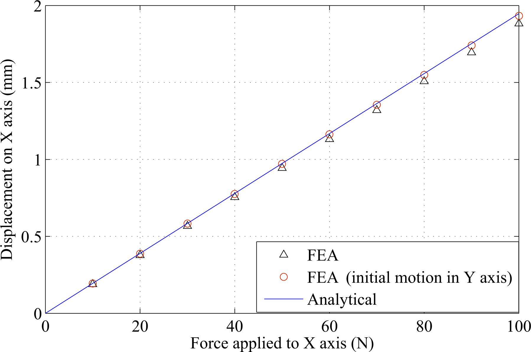
Figure 13Motion of the decoupling mechanism in x axis given the maximum displacement in y axis.
To validate the proposed conceptual design, numerous FEA simulations are conducted in this section. Note that the large deflection mode is chosen in the FEA analysis, and the maximum element size of the beams is set to 0.5 mm.
5.1 Modal analysis
Figure 10 shows the FEA results of the modal analysis of the first six orders. The first two orders correspond to the translational motion of the two actuation axes, and the third order corresponds to the rotational motion. Compared with the conventional design, the third order modal is not much higher than the first two ones. It means that the rotational stiffness does not increase by the proposed SASC-based design.
5.2 Motion simulations
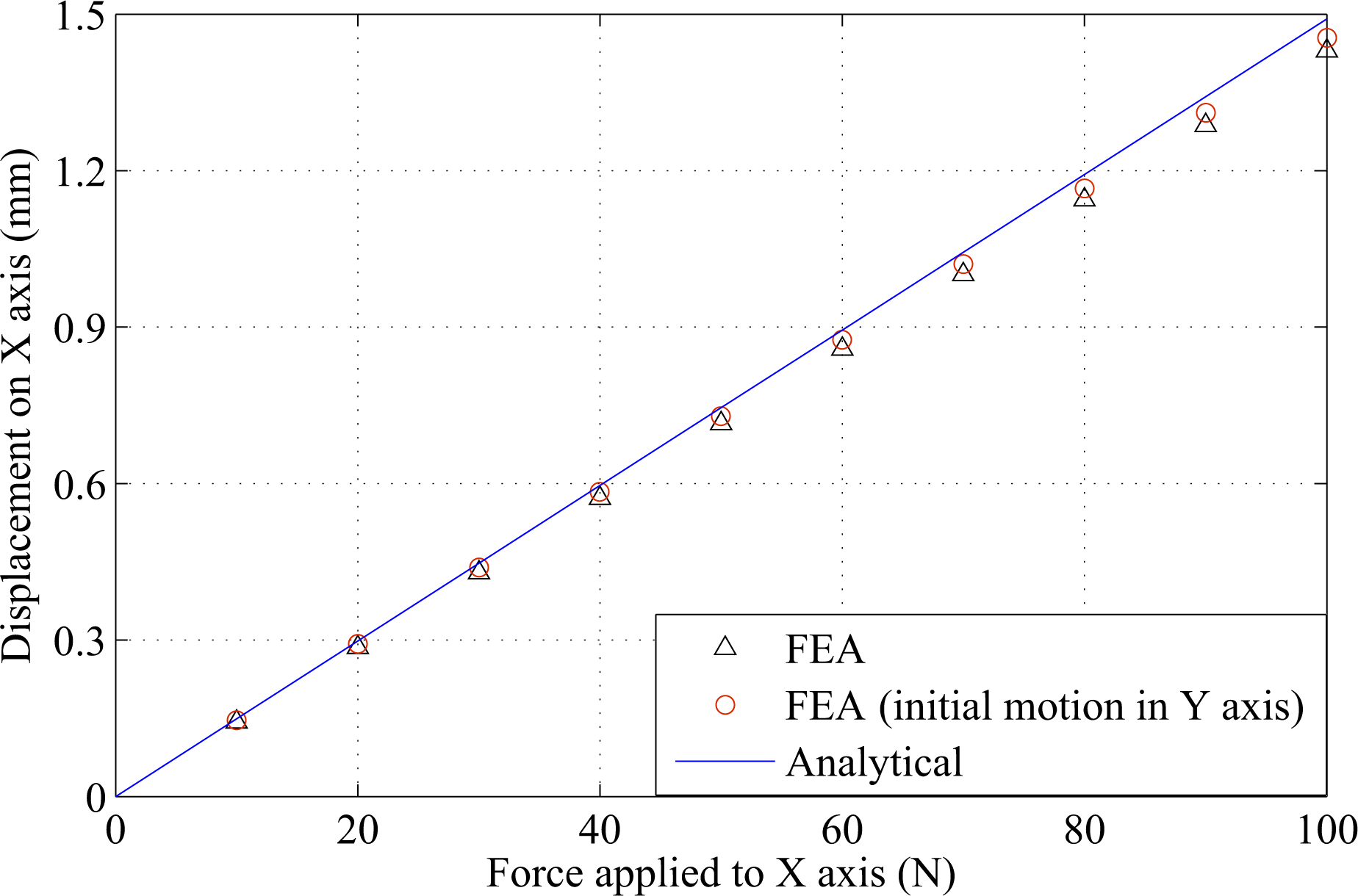
Due to the identity of the two actuation axes, the simulation of the motion performance is only conducted for x axis, and the results of y axis can be performed as well. Figure 11 shows the applied forces to the redundant constraint module, decoupling mechanism and the stage. Figures 12–14 show the results of translational motions of the redundant constraint module, the decoupling mechanism and the overall stage, respectively. It is seen from Fig. 14 that the designed stage is capable of achieving desired millimeters stroke with 100 N actuation force.
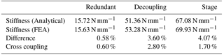
To calculate the the cross coupling error, we set the cross coupling percentage as
where is the displacement in x axis while the maximum force Fmax is applied to y axis, and = 0 is the displacement in x axis while there is no force applied to y axis. In the simulations, the initial motion in y axis means that the maximum displacement (1.5 mm) is given in y axis. As a result, there is an initial axial force applied to x axis. To better show the results of Figs. 12–14, we compare the results in Table 3. It is seen from Table 3 that the cross-axis coupling of the SASC-based redundant constraint module is much better than that of the decoupling mechanism without the SASC (0.6 versus 2.8 %). Also the cross-axis coupling of the overall stage is 1.7 %, which is in a reasonable good range (1–2 %) from the literature, for example (Hao and Kong, 2012).
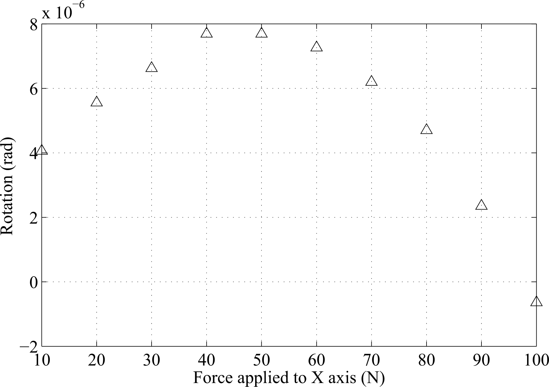
Figure 15Parasitic rotation of the proposed stage (moves along x axis with initial motion on y axis).
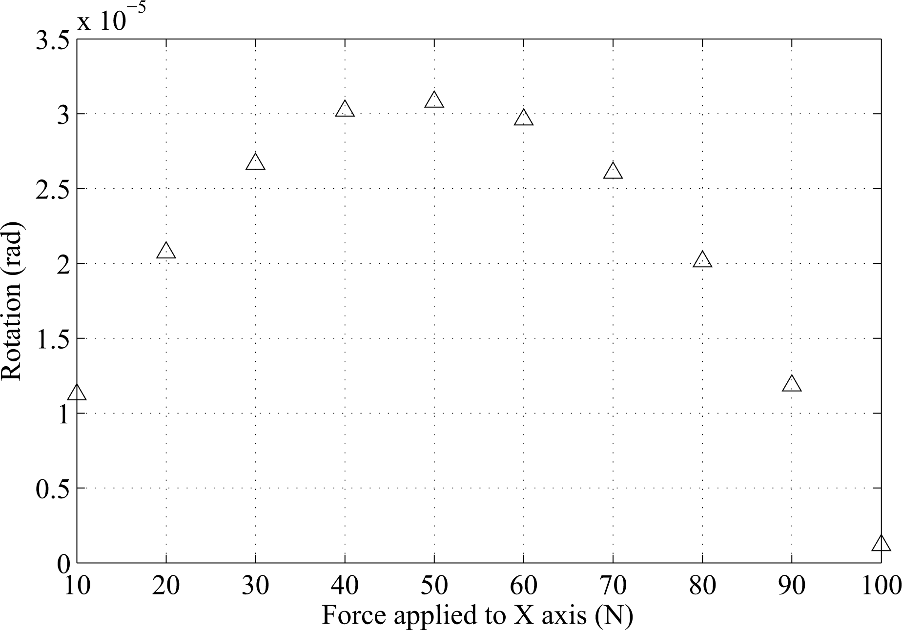
Figure 16Parasitic rotation of the stage without the SASC (moves along x axis with initial motion in y axis).
5.3 Results on parasitic rotation
In this subsection, the simulation of the parasitic rotation is conducted. As a result, the parasitic rotation of the redundant constraint is < 1 µrad, which demonstrates the performance of the proposed SASC-based design. And the parasitic rotation of the decoupling mechanism is below 40 µrad. One possible reason is mainly due to the relatively low rotational stiffness. The parasitic rotation of the proposed stage is shown in Fig. 15, where the parasitic rotation is < 8 µrad. The maximum parasitic rotation occurs when the motion stage reaches to its middle stroke, and this result agrees with the shape of the moment variation.
In order to demonstrate the advantage of the proposed SASC-based design, another XY nanomanipulator without SASC is analyzed as shown in Fig. 16. The two nanomanipulators are designed with the same rotational stiffness. Comparing Fig. 15 with 16, it is clear that the one with the SASC has much better performance on reducing the parasitic rotation.
We have proposed a novel SASC-based design to restrict the parasitic rotation of XY compliant mechanisms. The proposed design is especially preferred for large stroke XY beam flexure-based nanomanipulators, where the parasitic rotation is non-negligible. Instead of increasing the rotational stiffness of the motion stage, the proposed SASC design reduces the in-plane moment of force. It is shown from the SASC that by leveraging on the varied stiffness of parallelogram flexure, the stiffness center can be made stationary by appropriately setting the corresponding geometric parameters, and hence the parasitic rotation is restricted. A case study provides the design of the SASC-based large stroke XY compliant nanomanipulator. The corresponding FEA simulation results show that without increasing the rotational stiffness, the parasitic rotation is less than 8 µrad at the stroke of 1.5 mm. This demonstrates that the proposed SASC can be utilized as an alternative to significantly reduce the parasitic rotation of large stroke XY beam flexure based nanomanipulators.
The data generated during this study are available from the corresponding author on reasonable request.
The authors declare that they have no conflict of interest.
The authors would like to acknowledge the support from the Open Foundation of
the State Key Laboratory of Tribology & Institute of Manufacturing
Engineering under Grant No. SKL2016B05, the National Natural Science
Foundation of China under Grant No. 61327003, and the Fundamental Research
Funds of Shandong University under Grant No. 2015JC034.
Edited by: Guangbo Hao
Reviewed by: Junyi Cao and one anonymous referee
Awtar, S. and Parmar, G.: Design of a large range XY nanopositioning system, J. Mech. Robot., 5, 021008-1–021008-13, 2013. a
Awtar, S., Slocum, A. H., and Sevincer, E.: Characteristics of beam-based flexure modules, J. Mech. Design, 129, 625–639, 2007. a, b
Awtar, S., Shimotsu, K., and Sen, S.: Elastic averaging in flexure mechanisms: a three-beam parallelogram flexure case study, J. Mech. Robot., 2, 041004-1–041004-12, 2010. a
Chen, G. and Bai, R.: Modeling large spatial deflections of slender bisymmetric beams in compliant mechanisms using chained spatial-beam-constraint-model, J. Mech. Robot., 8, 041011-1–041011-9, 2016. a
Hao, G.: A 2-legged XY parallel flexure motion stage with minimised parasitic rotation, Proc IMechE Part C, J. Mech. Eng. Sci., 228, 3156–3169, 2014. a
Hao, G. and Kong, X.: A novel large-range XY compliant parallel manipulator with enhanced out-of-plane stiffness, J. Mech. Design, 134, 061009-1–061009-9, 2012. a, b, c
Hao, G. and Li, H.: Extended static modeling and analysis of compliant compound parallelogram mechanisms considering the initial internal axial force, J. Mech. Robot., 8, 041008-1–041008-11, 2016.
Hao, G. and Yu, J.: Design, modelling and analysis of a completely-decoupled XY compliant parallel manipulator, Mech. Mach. Theory, 102, 179–195, 2016. a
Howell, L. L., Magleby, S. P., and Olsen, B. M.: Handbook of compliant mechanisms, Wiley, New York, USA, 79–146, 2013. a
Shang, J., Tian, Y., Li, Z., Wang, F., and Cai, K.: A novel voice coil motor-driven compliant micropositioning stage based on flexure mechanism, Rev. Sci. Instrum., 86, 957–978, 2015. a
Xu, Q.: Design and development of a compact flexure-based XY precision positioning system with centimeter range, IEEE T. Ind. Electron., 61, 893–903, 2014. a
Yu, J., Xie, Y., Li, Z., and Hao, G.: Design and experimental testing of an improved large-range decoupled XY compliant parallel micromanipulator, J. Mech. Robot., 7, 044503-1–044503-6, 2015. a
Zhang, Z., Wang, P., Yan, P., and Guan, Y.: A beam flexure-based nanopositioning stage supporting laser direct-write nanofabrication, Sci. China Phys. Mech., 59, 684211-1–684211-6, 2016. a
Zhang, Z., Liu, Z., and Yan, P.: Design of a flexure-based XY positioning stage with balanced axial forces on decoupling modules, IEEE International Conference on Manipulation, Manufacturing and Measurement on the Nanoscale, Chongqing, China, 18–22 July 2016, 83–88, 2017. a
Zhao, H., Han, D., Zhang, L., and Bi, S.: Design of a stiffness-adjustable compliant linear-motion mechanism, Precis. Eng., 48, 305–314, 2017. a