the Creative Commons Attribution 4.0 License.
the Creative Commons Attribution 4.0 License.
 | 24 Jul 2018
FE analysis of circular CFT columns considering bond-slip effect: A numerical formulation
Ju-Young Hwang
Hyo-Gyoung Kwak
In this paper, a numerical model for the analysis of bond-slip occurring in concrete filled steel tube (CFT) columns is introduced. Unlike the classical bond-link or bond-zone element using double nodes, the introduced model considers the bond-slip effect without taking double nodes by incorporation of the equivalent steel stiffness. Upon constructing the equations system on the basis of the force equilibrium and the compatibility condition at each nodal point, the deformations in a steel tube are determined, followed by evaluation of the bond-slip. Moreover, as a part of solving the equations system to evaluate the slip behavior, the mechanical properties for steel and bond-slip have been changed and updated through an iteration procedure. Finally, the validity of the introduced numerical model is verified by comparing the experimental data with the analytical results for CFT columns subjected to axial force and bending moment.
- Article
(7310 KB) - Full-text XML
- BibTeX
- EndNote


Concrete-filled steel tube (CFT) columns, which consist of a circular or rectangular steel tube filled with concrete, have been increasingly applied to column design and popularly adopted in buildings and bridges due to their excellent resisting characteristics. Since the steel tube provides triaxial confinement in much the same way as a stirrup in a reinforced concrete (RC) column, while carrying a portion of the applied axial force and bending moment, advantages in structural behavior such as increased strength, stiffness and ductility can be expected relative to ordinary RC columns (Shams and Ala Saadeghvaziri, 1997; Shanmugam and Lakshmi, 2001; Susantha et al., 2001; Bradford et al., 2002; Portolés et al., 2011). An additional advantage can also be obtained with respect to the construction sequence because the steel tube serves as formwork during the pouring of in-filled concrete (Schneider, 1998; Goto et al., 2010).
To examine the overall performance of CFT columns, various experimental studies have been performed (Choi et al., 2017; Chen et al., 2017; McCann et al., 2015) after Schneider (1998), and Huang et al. (2002) tested CFT columns having circular and square cross sections to investigate the effect of the steel tube wall thickness and the diameter-to-thickness (D∕t) ratio on the column strength. Nevertheless, the structural behavior of CFT columns is still not well defined. In particular, the composite action between the concrete core and the steel tube makes it difficult to precisely evaluate the mechanical behavior of the structure. In addition, the different Poisson's ratios of the constituent materials of steel and concrete may cause a smaller confinement effect than expected, and the occurrence of slip along the interface between the concrete core and the steel tube leads to a decrease of the strength of CFT columns (Hajjar and Gourley, 1996; Johansson and Gylltoft, 2002; Kwon et al., 2005). Therefore, additional experimental studies should continuously be performed to precisely evaluate the nonlinear behavior and the ultimate resisting capacity of CFT columns and to supply basic information for the construction of design equations.
In parallel with experimental studies, reliable numerical approaches have also been conducted (Goto et al., 2010; Hu et al., 2005; Moon et al., 2012) with the introduction of analytical models. The development of an analytical model for the response of CFT columns, however, requires an exact simulation of the contact behavior between the concrete core and the steel tube, because the accuracy of the numerical results is dominantly affected by both the bond-slip behavior and the confinement effect induced by the contact behavior between the concrete core and the steel tube. Many researchers, including Hibbitt and Sorensen, Inc. (2000), have simulated the contact behavior along the interface with the use of a proper friction coefficient because of its simplicity in application. However, this approach requires an indirect implementation of the confinement effect on the in-filled concrete because direct delivery of the stress between the in-filled concrete and the steel tube cannot be defined (Goto et al., 2010; Moon et al., 2012).
To remove this limitation and to directly consider the confinement effect with the bond-slip behavior, the bond-link element, which connects a node of a concrete finite element with a node of an adjacent steel element, was introduced. This element (Kwon et al., 2005; Kwak, 1994; Yin and Lu, 2010) has been commonly used in the finite element analysis of CFT columns. A few numerical analyses considering the bond-slip effect have been conducted by using the bond-link element (Bashir et al., 2010; Kwak and Kim, 2010; Li et al., 2012). However, owing to the complications in the numerical modeling with a considerable increase in the number of degrees of freedom caused by the use of double nodes, most finite element studies of CFT columns do not take into account the bond-slip developed at the interface between the concrete core and the steel tube (Johansson and Gylltoft, 2002; Kwon et al., 2005). Notably, the use of a fine mesh in modeling CFT columns increases the difficulty in the numerical modeling.
To address this issue, this paper introduces an improved numerical approach that can consider the bond-slip effect without the use of double nodes at the interface between the concrete core and the steel tube by incorporating the equivalent steel stiffness. The basic concept of this numerical design was introduced by Kwak and Kim (2001) and was derived from the bond-slip relation of a RC beam. Kwak and Kim applied the adjust stiffness matrix found through iteration that simulates a similar strain to the actual bond-slip behavior. However, since the Kwak and Kim model was developed for beam elements and the loading condition was limited to uniaxial load, an improved bond-slip model should be suggested to simulate CFT columns. In the bond-slip model proposed in this paper, after calculating the nodal displacements, the deformation of steel at each node can be found through the back-substitution technique from the first to the final steel element using a governing equation constructed on the basis of the force equilibrium at each node of the steel tube and the compatibility condition between the concrete core and the steel tube. The developed algorithm can also be implemented in many commercialized programs including ABAQUS (2013) and ADINA (2015) as a user defined material model, and the validity of the proposed numerical modes is established through correlation studies between the numerical results and the experimental data for CFT columns subjected to various monotonic loadings.
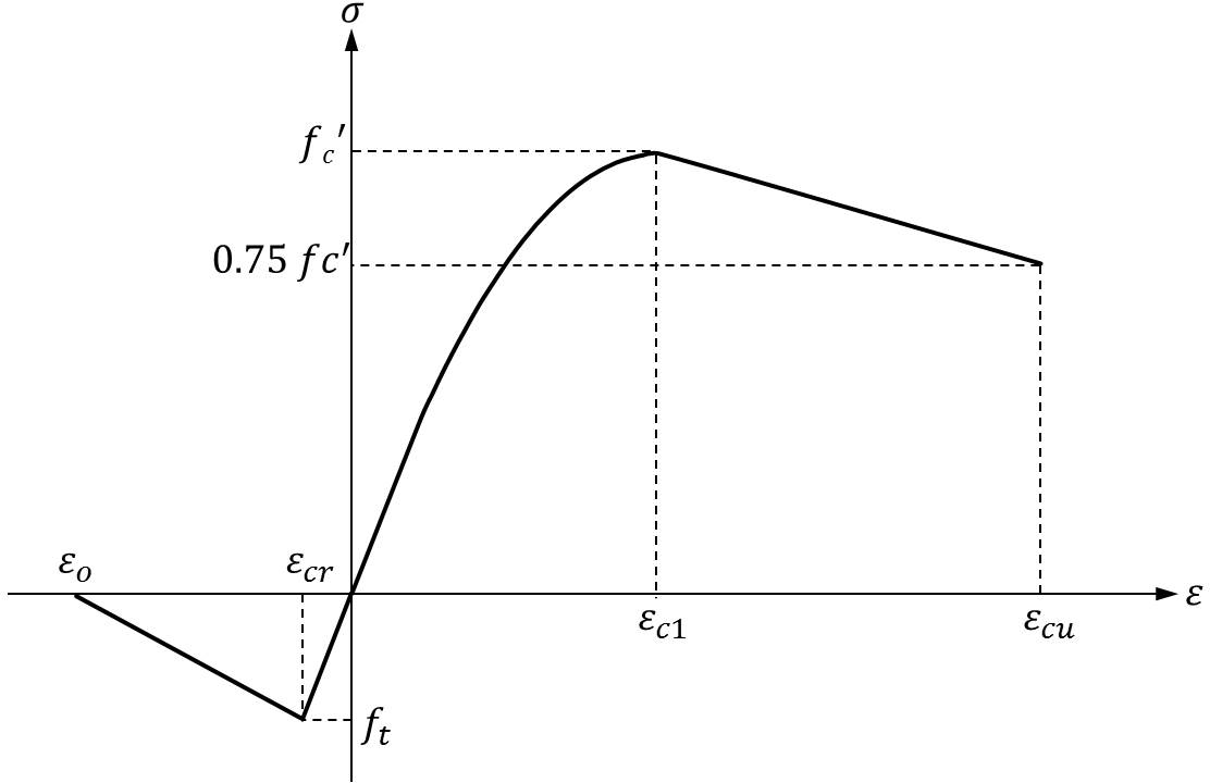
Since concrete is mainly used for compression members, the stress-strain relation of concrete in compression should be considered significantly, and the monotonic envelope curve of stress-stain for concrete introduced by Kent and Park (1971) and later modified by Scott et al. (1982) is adopted in this paper, because of its simplicity and computational efficiency. This model describes the monotonic concrete stress-strain relation in compression as a second-degree parabola accompanying the linear descending branch after reaching the compressive strength, as shown in Fig. 1.
On the other hand, the tensile behavior of concrete is assumed to be linear elastic until reaching the tensile strength. After the tensile strength, the tensile stress decreases linearly with an increase of the principal tensile strain up to reach εO in Fig. 1, which represents the ultimate failure strain by cracking (Kwak and Kim, 2001). To describe the cracking behavior, in advance, the damaged plasticity model (Lubliner et al., 1989) among the cracking models defined in ABAQUS is adopted because this model shows not only less sensitivity to the mesh topology but also stable convergence to the solution even in the local failure zone where a stress concentration is expected.
In addition, as a part of considering the confinement effect, the use of augmented compressive strength and corresponding strain through the introduction of material coefficients has been considered in previous studies while defining the stress-strain relation of concrete (Goto et al., 2010; Hu et al., 2005; Hibbitt and Sorensen, Inc., 2000; Gupta et al., 2014), where the material coefficients are usually defined as the ratio of the diameter of in-filled concrete D to the thickness of the steel tube t. However, the use of material coefficients has been based on the premise of considering the contact behavior between the in-filled concrete and the steel tube by the simple friction model which cannot reflect the stress transfer effectively. On the other hand, since the numerical model introduced in this paper is based not on the friction model but rather on the gap element model which directly connects a node of a concrete finite element with a node of an adjacent steel element, additional consideration of material coefficients is not necessary (Moon et al., 2012; Leon and Hu, 2008).
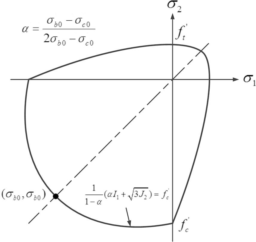
Moreover, the multi-axial behavior of concrete must be defined to simulate the three-dimensional behavior of concrete induced from the confinement by the steel tube. Under combinations of multi-axial loading, concrete exhibits strength and stress-strain behavior that are different from those under uniaxial loading conditions. The strength envelope proposed by Lee and Fenves (1998) and defined in ABAQUS (2013) is adopted in this paper. This envelope, which is defined for the compression-compression region, is slightly different from Kupfer's failure envelope (Kupfer and Gerstle, 1973) obtained through a panel test. As shown in Fig. 2, σ1 and σ2 are the principal stress along the first and second axis, σc0 is the uniaxial initial yield compressive stress, σb0 is the biaxial initial yield compressive stress, and , and , where is the effective stress deviator. More details related to the strength envelope can be found elsewhere (Lee and Fenves, 1998). On the other hand, steel is assumed as a linear elastic, linear strain hardening material, and the post-yielding behavior under multi-axial loading is based on the Von-Mises yield criterion (ABAQUS, 2013).
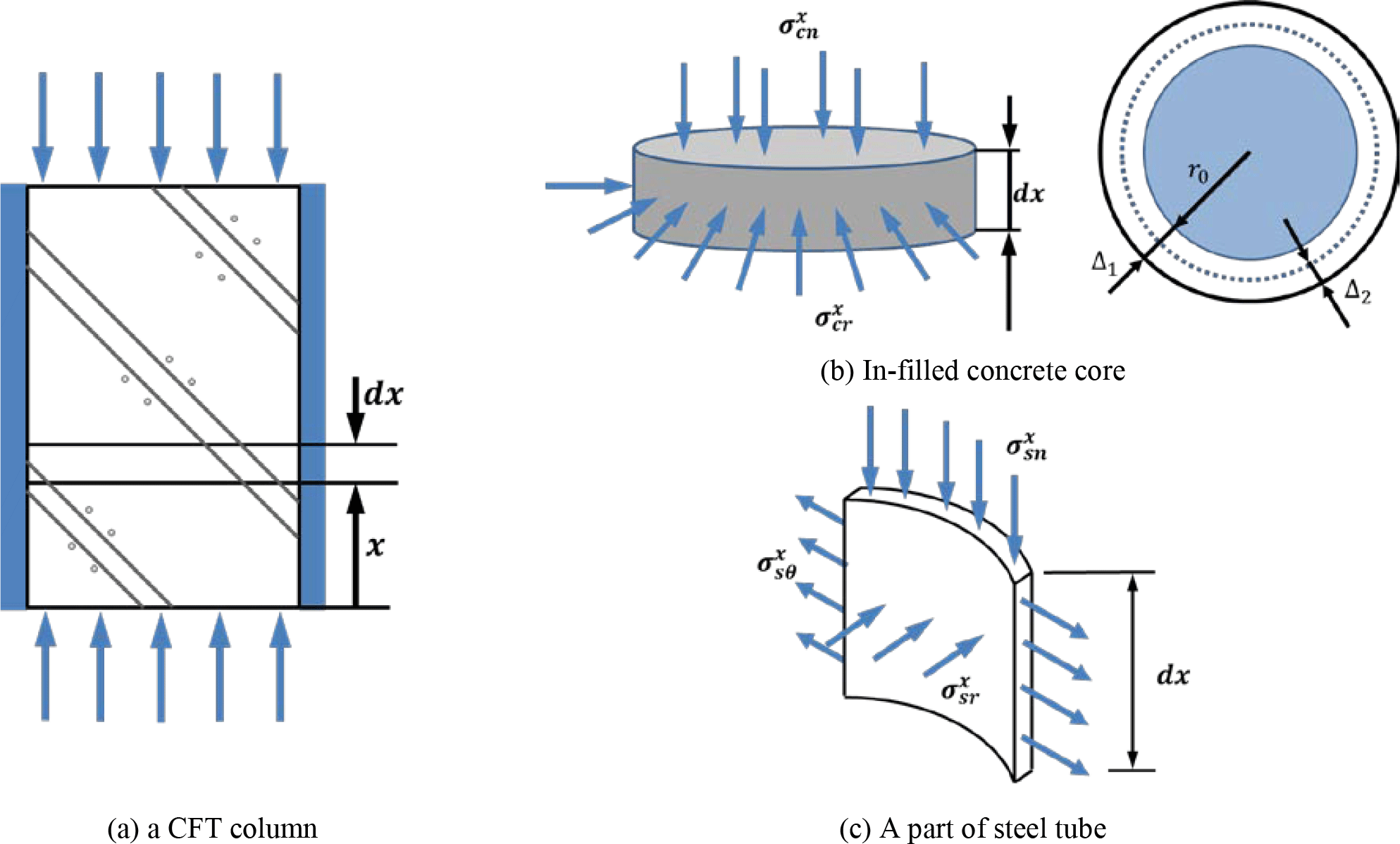

When a compressive force is applied to a circular CFT column, both the in-filled concrete and the steel tube will be subjected to not only normal stress but also stress in the radial direction, which develops a confinement effect. The interaction behavior between the in-filled concrete and the steel tube can then be derived on the basis of a perfect bond, where it is assumed that all the displacements of the in-filled concrete and the steel tube developed at the interface are identical.
Figure 3 shows the stress state of an in-filled concrete core and a steel tube in the equilibrium condition at an arbitrary location at a distance x from the loading point. From the strain compatibility in the axial direction (), the normal stress of concrete and steel can be expressed as , and , where , , εcn and εsn represent the normal strains of concrete and steel, σcn and σsn are the corresponding normal stresses, Ac and As denote the cross sectional area of in-filled concrete and the steel tube, and P is the applied axial force.
To evaluate the radial stress in the steel tube (, the elongation of the steel tube in the radial direction (see Fig. 3b) should be determined first, where Δ1 and Δ2 represent the radial displacements developed by the independent application of the normal stress () and the radial stress () into the in-filled concrete, respectively. From Hook's law (Barber, 2010), , and , where νc represents the Poisson's ratio of concrete. Since the radial strain , the strain in the radial direction can be expressed in terms of the radial stress. In advance, the stress-strain relation between the stresses in r, θ, and x direction and the corresponding strains makes it possible to uniquely determine the radial and circumferential stresses of and in the steel tube (see Fig. 3c).
Differently from the perfect bond case, however, to consider the bond-slip effect it is necessary to define the different displacement fields between the in-filled concrete and the steel tube, and to this end the bond-link element defined by a spring element connecting a concrete node and an adjacent steel node is usually adopted. Since the link element has no physical dimension, the two connected nodes originally occupy the same location in the finite element (FE) mesh of the structure before deformation.
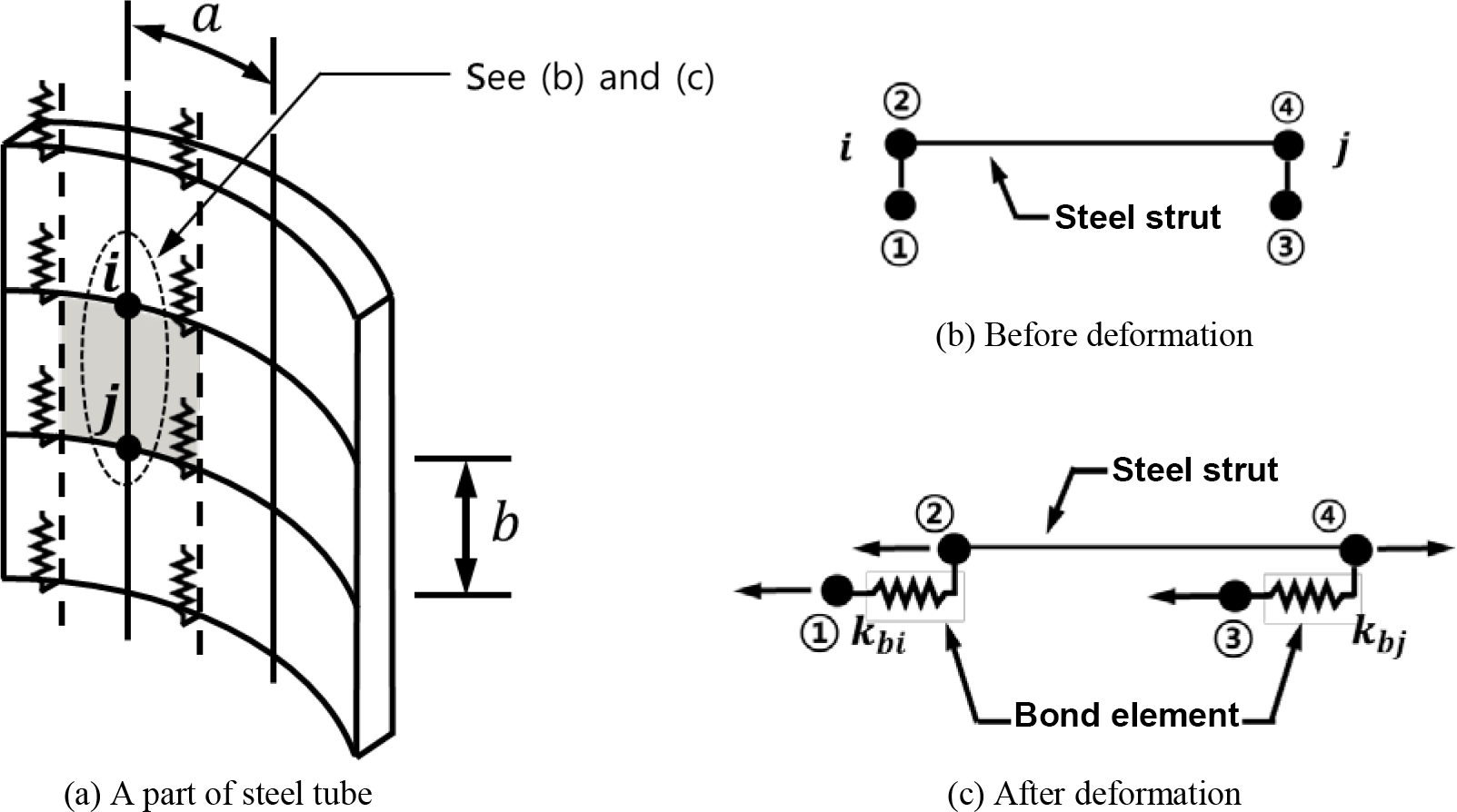
As shown in Fig. 4, an axial force applied to a CFT column is carried partly by the in-filled concrete (Fc) and partly by the steel tube (Fs), and a part of column can be considered as a free body diagram (see Fig. 4a and b). The force equilibrium condition then produces the relations from Fig. 4a and from Fig. 3c, where and τb denote the bond force and bond stress, D is the diameter of the in-filled concrete, Eb is the slip modulus, and m is the number of springs with a spring constant of kb in the circumferential direction. Since δc and δs represent the axial deformation in concrete and steel, respectively, δc−δs gives the bond-slip developed at the interface between the in-filled concrete and the steel tube. From the equality condition of upon the linear slip assumption with , in advance, the spring constant kb can be expressed as follows:
where a and b represent the element width and length, respectively, in a finite element that has been covered by one bond-link element (see Fig. 5a).
The use of the bond-link element in the FE analysis of RC structures, however, mandates the use of a double node to represent the relative slip between the in-filled concrete and the steel tube. In a complex structure, this requirement leads to not only a considerable increase in the number of degrees of freedom but also greater complexity of the mesh definition. To address these limitations in using the bond-link element, an improved numerical model is proposed in this paper.
To determine the equivalent modulus of elasticity for the steel tube, the steel area covered by the adjacent two nodes, node i and node j, in Fig. 5a can be considered as a strut or tie. A convenient free body diagram that isolates the steel strut with the bond-link elements attached at its end points is then selected. Figure 5b and c show this element before and after deformation, where points 1 and 3 are associated with the in-filled concrete and points 2 and 4 are associated with the steel tube at nodes i and j, respectively. The corresponding degrees of freedom of the steel strut and concrete at each end are connected by the bond-link element, whose stiffness depends on the relative displacement between the steel tube and the in-filled concrete. With this assumption, the stiffness matrix that relates the end displacements along the axis of the steel strut with the corresponding forces can be expressed as follows:
where is the strut stiffness, kbi and kbj are the stiffness of the bond-link element determined in Eq. (1), and t is the thickness of the steel tube.
By considering the steel degrees of freedom in Eq. (2), the following relation between concrete displacements and corresponding forces results in , where , . After evaluating the inverse of [KSS] and carrying out multiplications, the equivalent stiffness is reduced to:
which is the local stiffness matrix of the steel strut element including the effect of bond-slip, and it is now apparent that bond-slip reduces the stiffness of the steel strut element. In advance, when the steel tube is modeled with shell elements, its stiffness is directly proportional to the modulus of elasticity. Therefore, the equivalent modulus of elasticity for the steel tube element can be inferred from Eq. (3) as
In the case of a perfect bond, the bond stiffness terms kbi and kbj become infinitely large and the equivalent modulus of elasticity is reduced to the elastic modulus of elasticity Es. The use of instead of Es makes it possible to consider the bond-slip effect without taking double nodes along the interface between the in-filled concrete and the steel tube.
Once the displacement increments at each node are determined for the current load increment, they can be transformed to the concrete displacement increments {Δuc at the ends of the steel strut element in the direction parallel to the axis of the steel strut element on the basis of the relation , where Nm is a shape function. Using the second row of Eq. (2), which expresses the condition of equilibrium of the steel strut element, the force and deformation increments in steel can now be determined by assembling the steel strut element matrices and imposing appropriate boundary conditions at the ends of the steel tube. Upon evaluating the steel displacement increments Δus, determination of the bond-slip at each node ({Δuc}−{Δus) and evaluation of the bond stiffness terms kbi and kbj become possible.
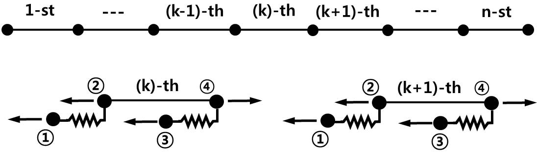

If the steel tube is assumed to be subdivided into n elements, as shown in Fig. 6, the relationship for the kth element can be rearranged as Eq. (5) from Eq. (2).
where it should be noted that the concrete displacement increments Δu1 and Δu3 are known from the global nonlinear finite element analysis of CFT columns. Solving Eq. (5) for the force and displacement increment at node 4 yields
where
For the transition from the kth to the (k+1)th element using the force equilibrium and the compatibility condition, Eq. (7) can be obtained:
and the substitution of Eq. (6) into Eq. (7) yields
where
Equation (8) relates the force and displacement increments at the beginning of steel element k+1 with those of steel element k. By applying Eq. (8) successively to elements k−1, k−2, ⋯, 2, 1 and summing the results, the following transfer matrix relation of Eq. (9) is derived. After replacing k+1 with n in Eq. (9) and applying Eq. (6) for element n, the following relation between the forces and displacements at the two ends of the steel tube can be obtained:
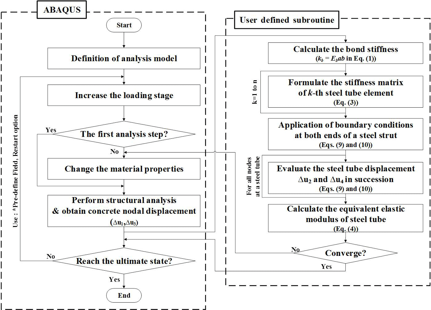
As the concrete displacement increments and two bounded conditions are already known at each end of the idealized steel stud element, it is now possible to solve Eq. (10) for the remaining two unknowns among four components of the forces and displacements, namely , , and . In the case of an axially loaded column, ΔF2 and Δu2 at mid-height or the supporting point of the CFT column can be considered as the two boundary values. After obtaining the force and displacement increments at one end of the steel stud, the displacement and the stress of the steel tube including the bond-slip at each node can be found through the successive application of Eq. (6), which expresses the condition of equilibrium of the steel tube. The state determination of the steel and bond elements can now be undertaken, yielding new steel and bond forces and updated stiffness matrices. The latter are only needed at the beginning of a new load step, when the stiffness matrix of the structure is updated. The substitution of the new material properties of steel and bond into Eq. (4) yields the equivalent elastic modulus of the steel tube. Differently from the linear bond-slip assumption considered in this paper, the use of any bond stress-slip relation such as the simple bilinear bond stress-slip relation makes it possible to take into account the change in the slip modulus after exceeding the bond strength. These solution steps are presented in some detail in the flow diagram of Fig. 7 for the analysis of the bond-slip behavior in a CFT column. In advance, all terms, excluding the first term, in the right-hand side of Eq. (10) may be ignored because of the relatively small nodal displacement of concrete, and this will produce a simpler solution procedure.

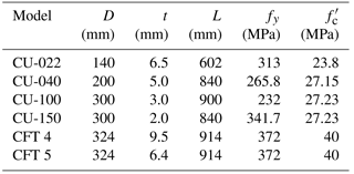
Table 1Dimensions and Material Properties of Specimens (Moon et al., 2012; Elremaily and Azizinamini, 2002).
ABAQUS 6.13 (2013) is used in the numerical analyses, and 8-node 3-D solid elements (named C3D8R element in ABAQUS) are adopted in the numerical modeling of both the in-filled concrete matrix and the steel tube, respectively. Moreover, to reserve consistency in the numerical modeling of all of the specimens considered in this paper, the mesh size of each finite element is based on an equal length of 20 mm regardless of the difference in the specimen size. The dimensions of are chosen for the modeling of the concrete matrix, and this size is determined through a convergence test for the FE mesh size. The same principle underlying numerical modeling is also applied to the steel tube and reinforcement.
4.1 CFT columns subjected to axial load only
In order to investigate the validity of the proposed bond-slip model, the experimental results of a CFT column tested by Kwon et al. (2005) have been used. This column is subjected to uniform compressive pressure on the in-filled concrete only, and Fig. 8 shows the layout for the gages and the geometric configuration for the specimen. The compressive strength of concrete is 57.1 MPa and the yield strength of steel is 265 MPa. In advance, the modulus elasticity values, 37.7 and 212.7 GPa, are used for concrete and steel tube upon the experiment. The test was conducted with an increase of the applied axial force up to P=50 t (490.3 kN) corresponding to 40 % of the ultimate resisting capacity of the specimen.
Figure 9 shows the distribution of steel stresses along the specimen at P=30 t (294.2 kN). The experimental results are compared with the numerical results according to the consideration of the bond-slip effect. The numerical results determined on the basis of the perfect bond assumption show remarkable differences from the experimental data, and this indicates that the perfect bond assumption has a limitation in predicting the structural behavior of CFT columns. Accordingly, the bond-slip effect must be considered to exactly evaluate the composite action in CFT columns. On the other hand, the numerical results obtained by considering the bond-slip effect present good agreement with the experimental results regardless of the difference in the numerical modeling according to the use of spring elements with double nodes or the use of the proposed bond model without double nodes. Since considering the bond slip effect results in less delivery of stress from the in-filled concrete to the steel tube, relatively smaller stresses than those obtained from the perfect bond assumption are developed. The minor differences between the two methods are caused by modeling details of the spring element and the equivalent stiffness by ABAQUS. However, this experimental verification still has a limitation because of the relatively lower applied axial load, which only leads to elastic behavior of CFT columns. If the verification is performed in the plastic region, the two methods give significantly different results relative to each other. The spring element cannot effectively reflect the change of material properties in plastification of the steel tube whereas the proposed model can take the change into account in the equivalent stiffness of the steel tube.
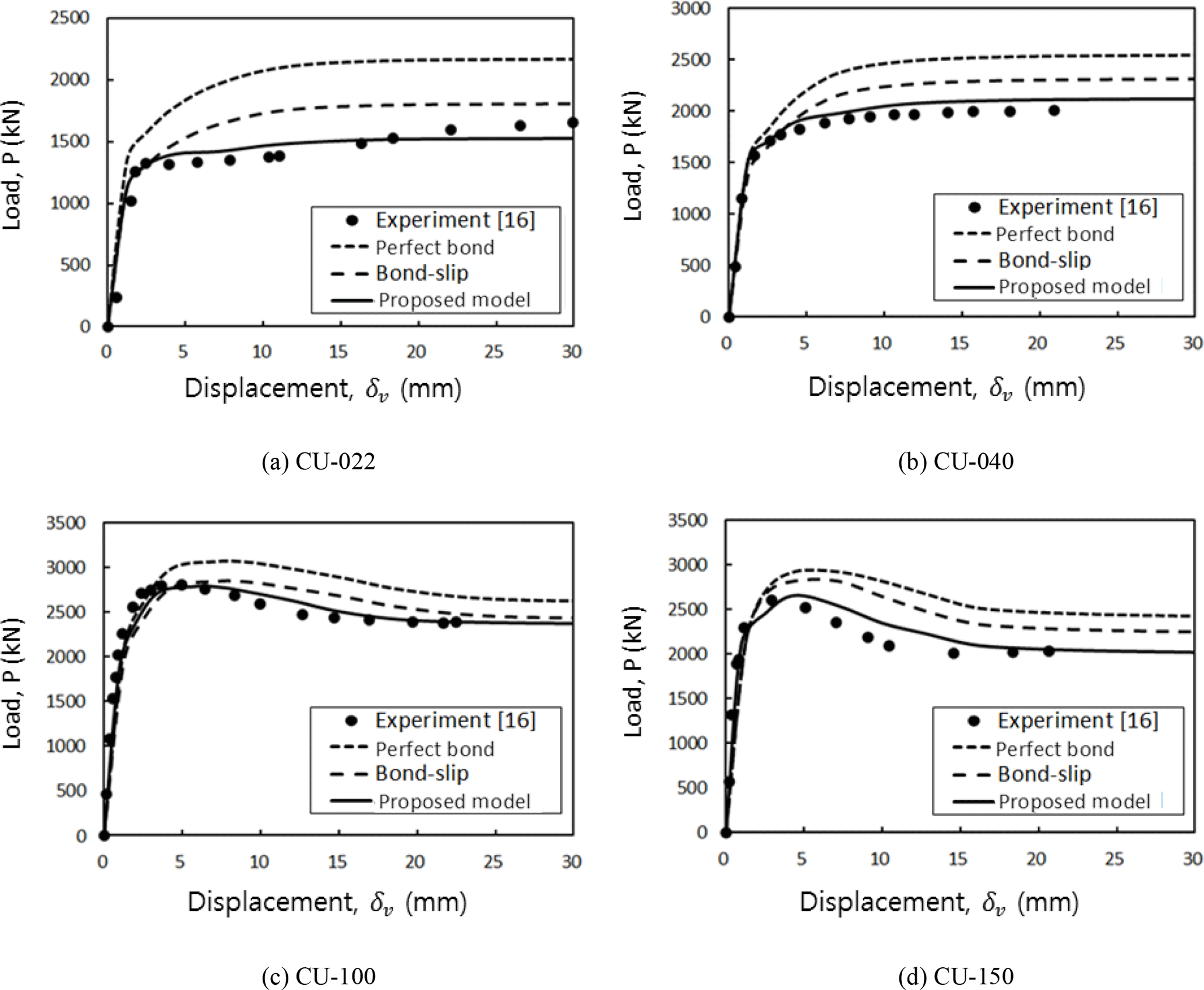
To validate the effectiveness of the proposed numerical model, four experimental results from several circular CFT columns tested by Schneider (1998) and Huang et al. (2002) are investigated first, and these experimental data have been widely used by many researchers (Moon et al., 2012) in correlation studies between numerical results and experimental data. The specimens are subjected to axial force only and the configuration and the corresponding dimensions of the specimens can be found in Fig. 10 and Table 1, respectively. Numerical analyses are conducted with displacement control on the top of the columns to achieve similar loading conditions to those of the experiment. Since the resisting capacity of the CFT column is dominantly affected by the ratio of D∕t, specimens with a wide range of D∕t ratio from 22 to 150 are considered in this paper. In Table 1, the extension in the specimen name represents the ratio of D∕t for the first four specimens.
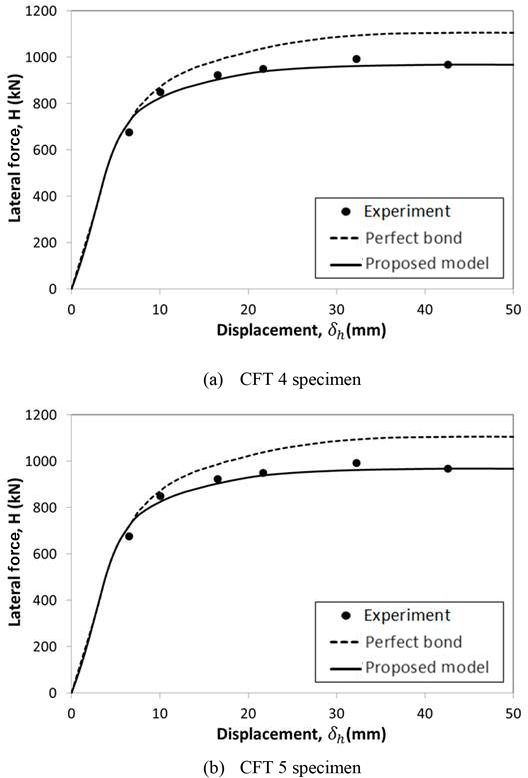
Figure 11 compares the analytical results with the measured load-displacement response of the specimens. As shown in this figure, the perfect bond assumption overestimates the energy absorption capacity, evaluated by the area under the load-displacement curve, as well as the ultimate load, and the overestimation appears to be enlarged with a decrease in the ratio of D∕t (compare Fig. 11a with 11d). This means that the use of a relatively thick steel tube causes larger bond-slip between the in-filled concrete and the steel tube because of the increasing resistance of the steel tube to bending behavior. On the other hand, a thin steel tube facilitates bending behavior united with the in-filled concrete while causing relatively small bond-slip at the interface.
The use of spring elements still gives reliable predictions for the structural response up to reaching the ultimate load. However, the maximum load is slightly overestimated at the post-yielding stage, and this over-estimation is consistently maintained with an increase of the bending deformation. This result appears to be caused by the use of the constant slip modulus Eb without any change corresponding to the developed bond-slip, even in the case where large slip occurs. On the other hand, the proposed bond model not only gives accurate predictions for the ultimate load but also effectively simulates the nonlinear behavior of CFT columns regardless of the ratio of D∕t.

4.2 CFT columns subjected to axial force and bending moment
The proposed numerical model is also applied to two CFT columns subjected to axial force and bending moment. These specimens were tested by Elremaily and Azizinamini (2002) with the purpose of quantifying the contribution of the steel tube to an increase of the energy dissipation capacity and ductility in CFT columns. The configuration of the test specimens can be idealized as a cantilevered member, as presented in Fig. 10, and the corresponding dimensions and material properties of the specimens can be found in Table 1. The applied constant axial forces are P=2694 kN and P=2167 kN for CFT 4 and CFT 5 specimens, and these forces correspond to 0.42 and 0.4Po, respectively, where Po represents the ultimate load determined by and Ac and As are the cross sectional area of concrete and steel, respectively. More details related to the test set-up and test procedure can be found elsewhere (Elremaily and Azizinamini, 2002).
The analytical responses for the horizontal drift δh of CFT 4 and CFT 5 specimens are compared with the experimental data in Fig. 12. The ultimate load capacity of CFT columns is governed by the yielding of the steel tube following the tensile cracking of the in-filled concrete. Very satisfactory agreement between the analysis and the experiment is observed. Figure 12 also shows that the introduced bond-slip model can effectively be used even at CFT columns representing bending behavior with axial deformation. On the other hand, the numerical results obtained by the perfect bond assumption overestimate the ultimate load, and the difference with the experimental results has been enlarged with a decrease of D∕t, as was observed in the case of CFT column specimens subjected to axial force only. This means that the bond-slip behavior is more dominant at CFT columns with a relatively small D∕t and this must be taken into consideration to exactly predict the ultimate load of CFT columns.
4.3 CFT columns subjected to double curvature bending test
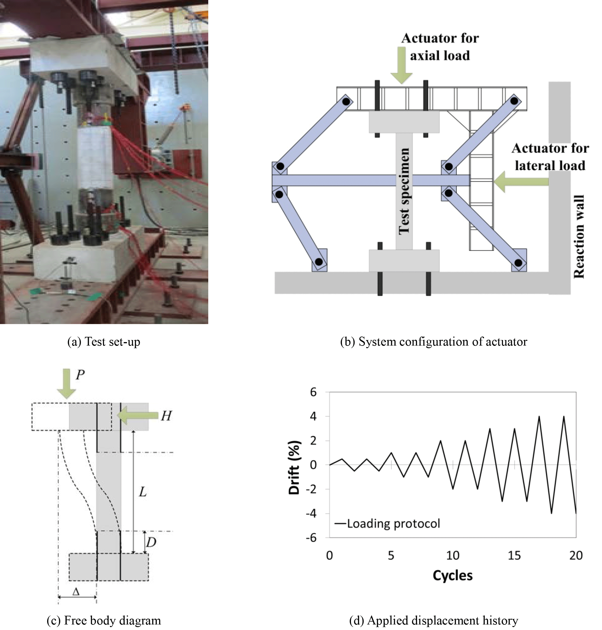
A correlation study for a CFT column subjected to double curvature bending is conducted for a specimen that was designed and experimentally evaluated by the authors. The dimensions and details of the test specimen are shown in Fig. 13. The strengthening by the steel tube was limited to the length of from both ends of the test specimen, because the development of maximum bending moment and plastic deformation accompanied especially after reaching the yielding moment of a RC column section is expected to be concentrated within this range. The ratio of the diameter of the in-filled concrete section (D) to the thickness of the steel tube (t) is , and the steel ratio by the embedded mild reinforcement is ρ=3.24 %. Since the specimen has a clamped boundary condition at both ends, the ratio of will be equivalent to in the cantilevered RC column. The used material properties are as follows: the compressive strength of concrete MPa, the yield strength of reinforcement fy=400 MPa, and the yield strength of steel tube fy=235 MPa.
The loads were applied to the specimen by actuators placed at the top face and at the mid-span of the specimen, as shown in Fig. 14b (Moon and Lee, 2014). The load at the mid-span is then transformed to the lateral load at the top face of the specimen through the parallelogrammatic apparatus, which was designed to prevent the rotational deformation accompanied by the horizontal drift at the top face of the specimen (see Fig. 14c). The applied axial load maintained a constant value of P=200 kN, but cyclic loading was applied for the lateral load H with displacement control up to reaching failure of the specimen. Figure 14d shows the horizontal displacement history introduced at the top face of the specimen.
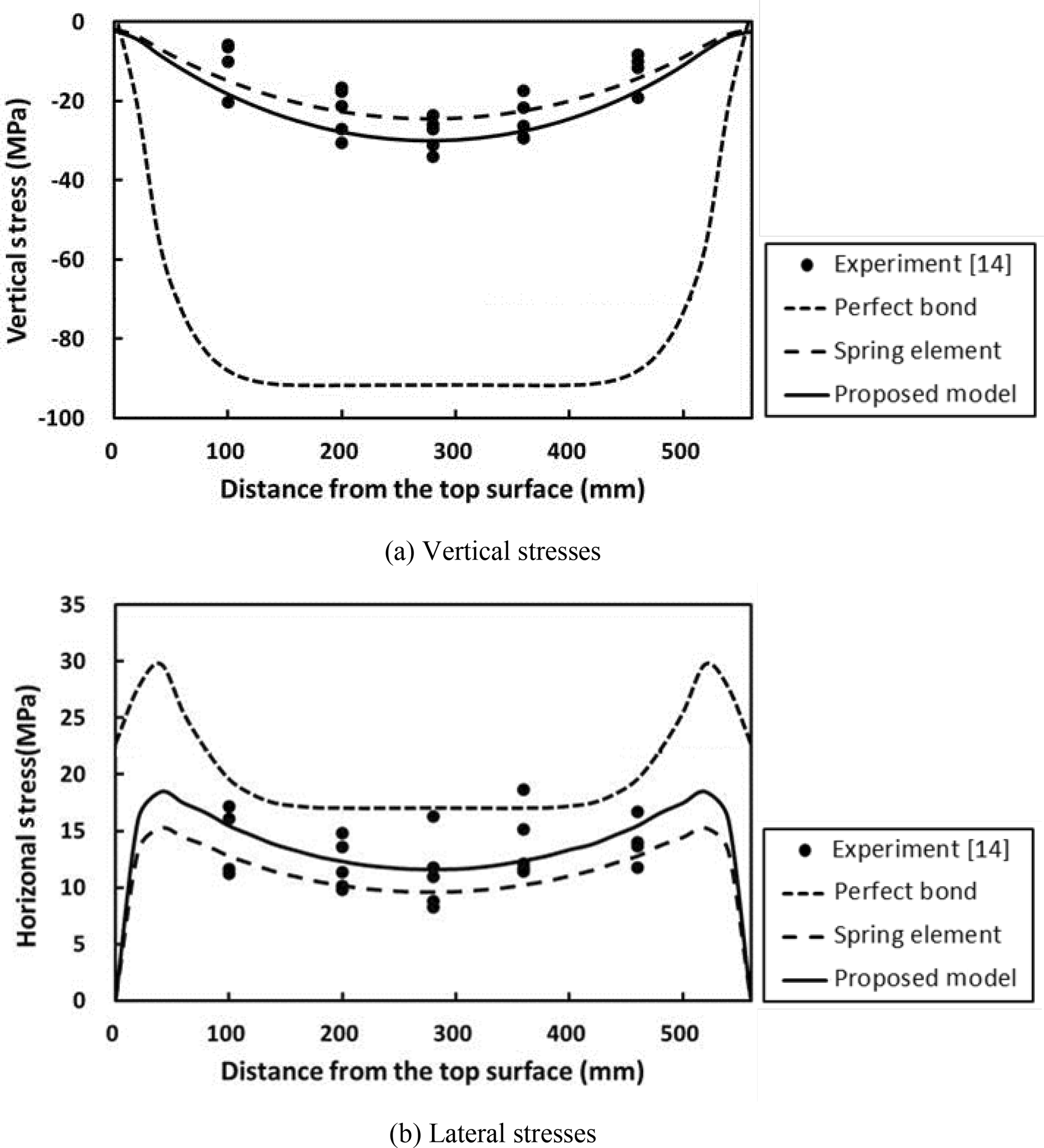
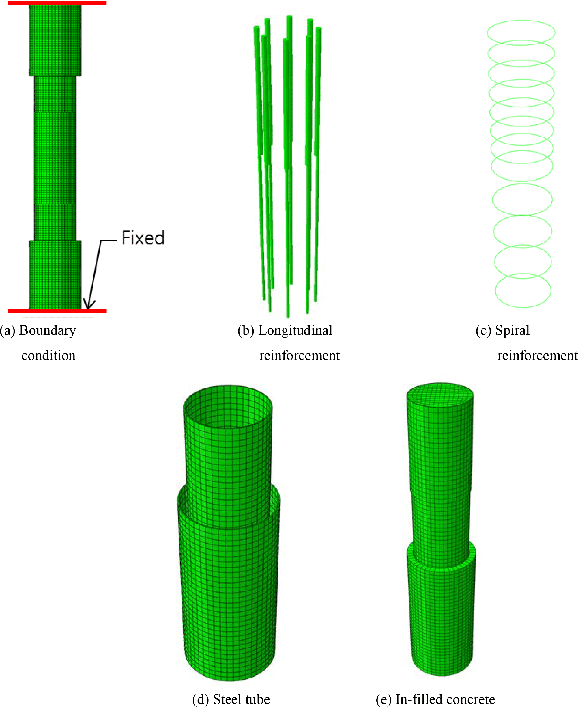
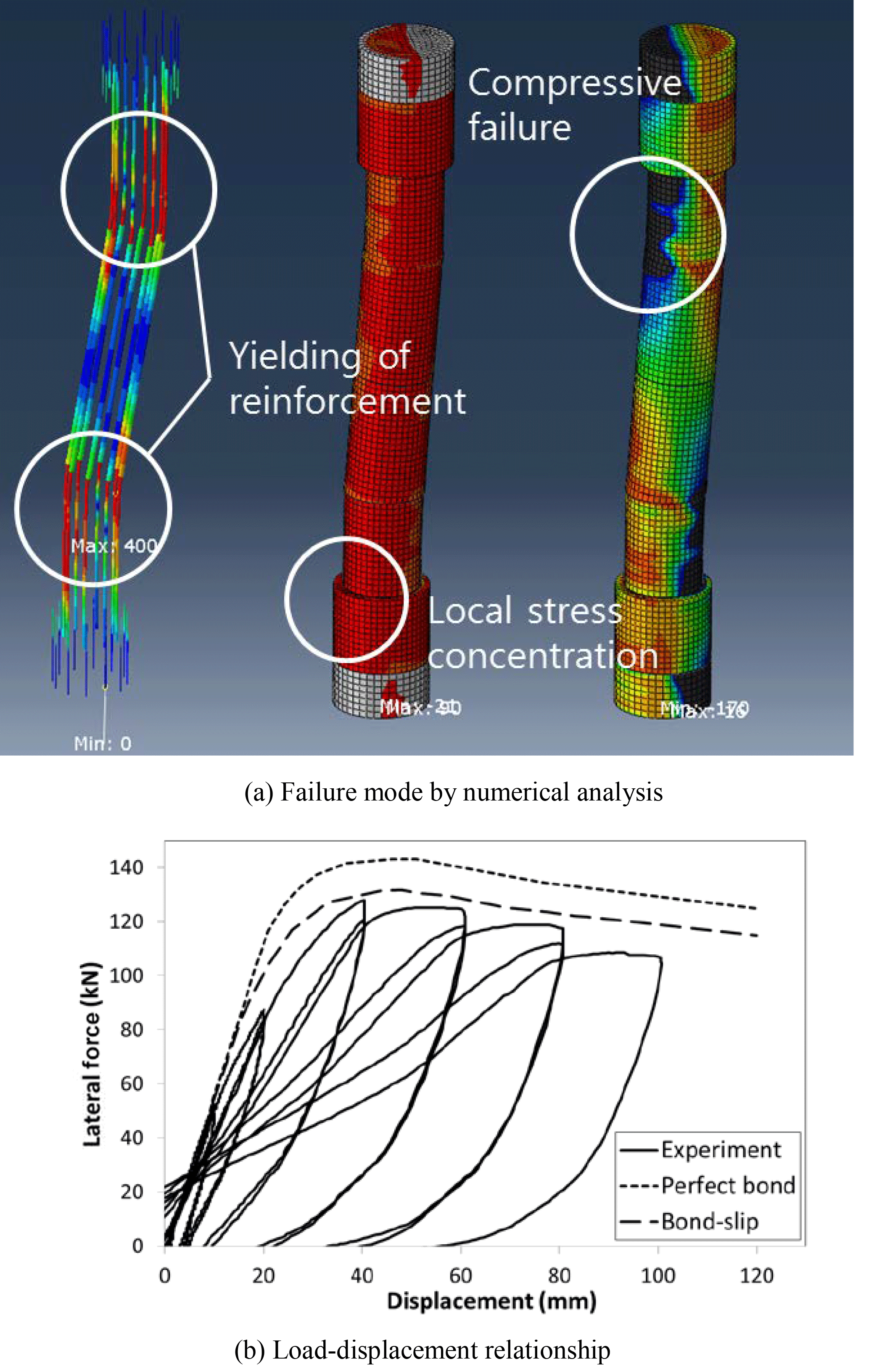
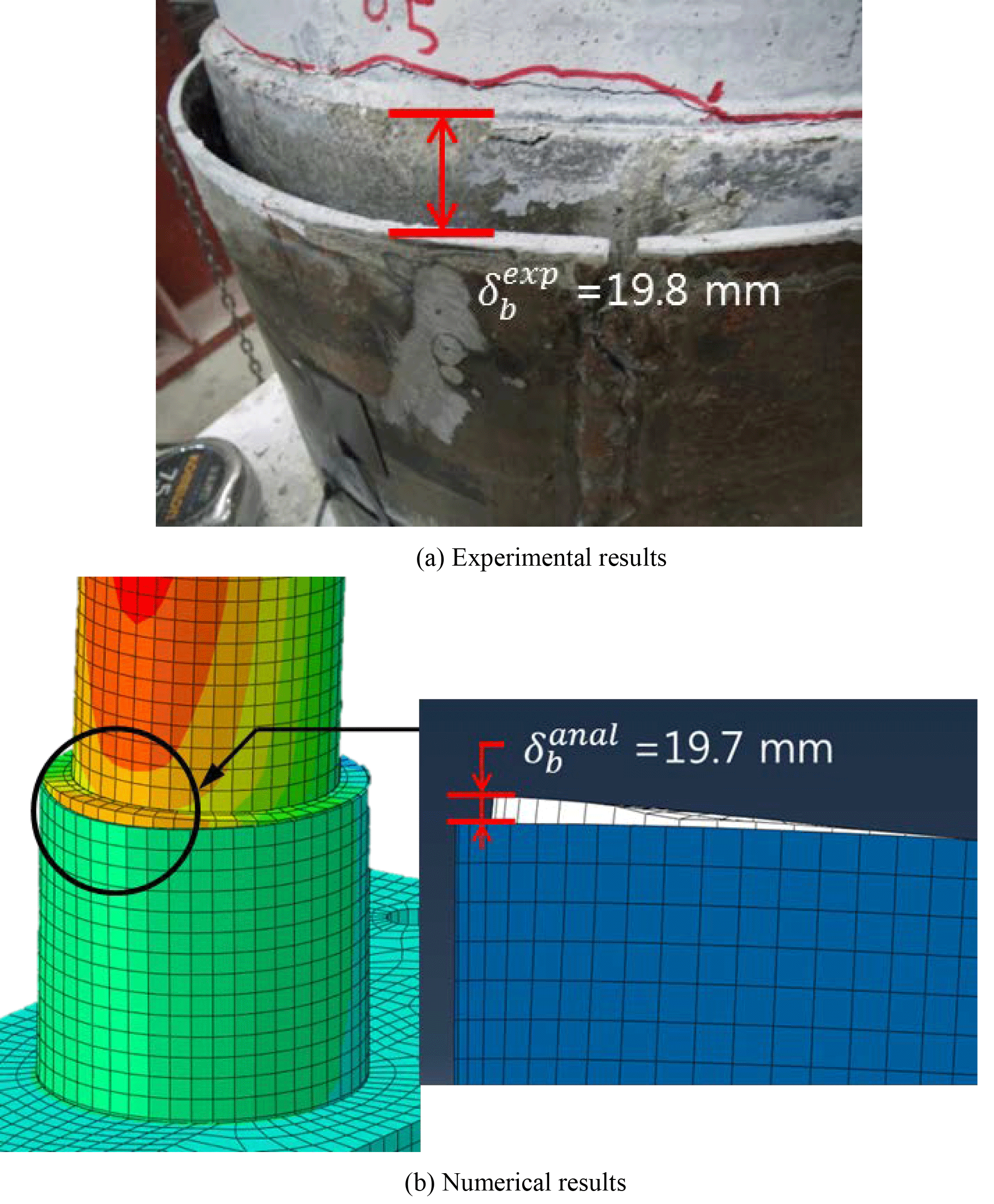
As shown in Fig. 15, full modeling of the experimental specimen is considered and fixed end boundary conditions are introduced at both end faces. Upon e introduction of the self-weight and a constant axial force of P=200 kN, the lateral load is imported with the designed displacement history in Fig. 14d. Figure 16 shows the obtained numerical results, presenting very good agreement with the monotonic envelope developed by the experimental data. However, the numerical results, in which the bond-slip effect is ignored, still overestimate the ultimate resisting capacity of the CFT column, even in a CFT column subjected to double curvature bending. Moreover, the slip behavior at the interface between the in-filled concrete and the steel tube can be found in Fig. 17. Because of the slip, the in-filled concrete was lifted up above the steel tube in the tensile region with the slip amount of . The slip amount calculated by the proposed analytical bond model is , which is almost the same as that obtained from experiments, and this means that the proposed model can effectively simulate the bond-slip behavior of CFT columns subjected to arbitrary loading type.
This paper introduces a slip model to take into account the bond-slip behavior in CFT columns. Differently from the classical spring element (bond-link element), which has many restrictions in numerical modeling because of the use of double nodes to represent the relative slip between the in-filled concrete and the steel tube, the introduced model, which does not use double nodes, can significantly reduce the number of nodes required to account for the bond-slip effect and will remove the difficulty arising in constructing a FE mesh in three-dimensional FE modeling. In advance, the introduced model can be implemented into many commercialized programs including ABAQUS (2013).
Through a comparison of numerical results and experimental data to verify the efficiency and applicability of the introduced slip model, the following conclusions have been drawn: (1) the bond-stress distribution shows a similar trend with the experimental results throughout the entire length of test specimens and is as reliable as the classical spring element; (2) when axial and lateral loads are applied separately, the load-displacement relationship of the test specimens shows good agreement with experiments; and (3) the load-displacement relationship of CFT columns subjected to a combined load of axial and bending is described well even with consideration of the secondary effect, and the failure mode and slip behavior simulated with the proposed bond-slip model are consistent with the experimental results. Accordingly, the introduced slip model, even with small error, can effectively be used to adequately predict the slip behavior as well as the ultimate load of CFT columns subjected to axial force and bending moment.
Data can be made available upon reasonable request. Please contact Hyo-Gyoung Kwak (kwakhg@kaist.ac.kr).
HGK suggested overall concept of this paper and details of the numerical bond-slip model. Also, he did the final examine of the whole paper. JYH applied the bond-slip model to CFT FEM model and verified with experiments and he set-up and performed the experiment to verify the suggested model.
The authors declare that they have no conflict of interest.
This work was supported by the National Research Foundation of Korea (NRF)
Grant funded by the Korean Government (MSIP)(No. 2017R1A5A1014883) and the
Korea Agency for Infrastructure Technology Advancement (KAIA) grant funded
by the Ministry of Land, Infrastructure and Transport (Grant 13IFIP-C113546-01).
Edited by: Amin Barari
Reviewed by: two anonymous referees
ABAQUS: Abaqus Analysis User's Manual version 6.13, Dassault Systèmes Simulia Corp., Providence, RI, USA, 2013.
ADINA: ADINA Handbook system 9.1, ADINA R&D, Inc., Watertown, MA, USA, 2015.
Barber, J. R.: Elasticity, 3rd edn., Springer, Dordrecht, Netherlands, 534, 2010.
Bashir, M. A., Nakayama, K., Furuuchi, H., and Ueda, T.: Numerical Simulation of Ultimate Capacity of Steel Pile Anchorage in Concrete-filled Steel Box Connection, Proceedings of JCI, 32, 1219–1224, 2010.
Bradford, M. A., Loh, H. Y., and Uy, B.: Slenderness limits for filled circular steel tubes, J. Constr. Steel Res., 58, 243–252, 2002.
Chen, Y., Feng, R., Shao, Y., and Zhang, X.: Bond-slip behaviour of concrete-filled stainless steel circular hollow section tubes, J. Constr. Steel Res., 130, 248–263, 2017.
Choi, I. R., Chung, K. S., and Kim, C. S.: Experimental study on rectangular CFT columns with different steel grades and thicknesses, J. Constr. Steel Res., 130, 109–119, 2017.
Elremaily, A. and Azizinamini, A.: Behavior and strength of circular concrete-filled tube columns, J. Constr. Steel Res., 58, 1567–1591, 2002.
Goto, Y., Kumar, G. P., and Kawanishi, N.: Nonlinear Finite-Element Analysis for Hysteretic Behavior of Thin-Walled Circular Steel Columns with In-Filled Concrete, J. Struct. Eng., 136, 1413–1422, 2010.
Gupta, P. K., Ahuja, A. K., and Khaudhair, Z. A.: Modelling, verification and investigation of behaviour of circular CFST columns, Struct. Concrete, 15, 340–349, 2014.
Hajjar, J. F. and Gourley, B. C.: Representation of concrete-filled steel tube cross-section strength, J. Struct. Eng., 122, 1327–1336, 1996.
Hibbitt, K. and Sorensen, Inc.: ABAQUS theory manual and user manuals, Version 5.8, Providence, R.I., 2000.
Hu, H. T., Huang, C. S., and Chen, Z. L.: Finite element analysis of CFT columns subjected to an axial compressive force and bending moment in combination, J. Constr. Steel Res., 61, 1692–1712, 2005.
Huang, C. S., Yeh, Y.-K., Liu, G.-Y., Hu, H.-T., Tsai, K. C., Weng, Y. T., Wang, S. H., and Wu, M.-H.: Axial Load Behavior of Stiffened Concrete Filled Steel Columns, J. Struct. Eng., 128, 1222–1230, 2002.
Johansson, M. and Gylltoft, K.: Mechanical behavior of circular steel-concrete composite stub columns, J. Struct. Eng., 128, 1073–1081, 2002.
Kent, D. C. and Park, R.: Flexural members with confined concrete, J. Struct. Div., 97, 1696–1990, 1971.
Kupfer, H. B. and Gerstle, K. H.: Behavior of concrete under biaxial stresses, J. Eng. Mech. Div.-ASCE, 99, 853–866, 1973.
Kwak, H. G.: Development of an Analytic Algorithm to Simulate Bond-Slip Effect, Journal of the Korean Society of Civil Engineers, 14, 711–719, 1994.
Kwak, H. G. and Kim, S. P.: Bond-slip behavior under monotonic uniaxial loads, Eng. Struct., 23, 298–309, 2001.
Kwak, H. G. and Kim, S. P.: Simplified monotonic moment–curvature relation considering fixed-end rotation and axial force effect, Eng. Struct., 32, 69–79, 2010.
Kwon, S. H., Kim, Y. Y., and Kim, J. K.: Long-term behaviour under axial service loads of circular columns made from concrete filled steel tubes, Mag. Concrete Res., 57, 87–99, 2005.
Lee, J. and Fenves, G. L.: Plastic-damage Model for Cyclic Loading of Concrete Structures, J. Eng. Mech.-ASCE, 124, 892–900, 1998.
Leon, R. T. and Hu, J. W.: Design of innovative SMA PR connections between steel beams and composite columns, Proc., 6th Int. Workshop on Connections in Steel Structures, Connections VI, AISC, 23–25 June, Chicago, IL, 513–524, 2008.
Li, W., Li, Q. N., and Jiang, W. S.: Parameter study on composite frames consisting of steel beams and reinforced concrete columns, J. Constr. Steel Res., 77, 145–162, 2012.
Lubliner, J., Oliver, J., Oller, S., and Onate, E.: A plastic-damage model for concrete, Int. J. Solids Struct., 25, 266–326, 1989.
McCann, F., Gardner, L., and Qiu, W.: Experimental study of slender concrete-filled elliptical hollow section beam-columns, J. Constr. Steel Res., 113, 185–194, 2015.
Moon, J. and Lee, H.-E.: Experimental evaluation of flexural behavior of partially embedded circular CFST pier-to-coping connection, Journal of Railway Conference, 2014, 1387–1392, 2014.
Moon, J., Lehman, D. E., Roeder, C. W., and Lee, H.-E.: Analytical modeling of bending of circular concrete-filled steel tubes, Eng. Struct., 42, 349–361, 2012.
Portolés, J. M., Romero, M. L., Bonet, J. L., and Filippou, F. C.: Experimental study of high strength concrete-filled circular tubular columns under eccentric loading, J. Constr. Steel Res., 67, 623–633, 2011.
Schneider, S. P.: Axially Loaded Concrete-filled Steel Tubes, J. Struct. Eng., 124, 1125–1138, 1998.
Scott, B. D., Park, R., and Priestley, M. J. N.: Stress-strain behavior of concrete confined by overlapping hoops at low and high strain rates, Journal Proceedings, 79, 13–27, 1982.
Shams, M. and Ala Saadeghvaziri, M.: State of the art of concrete-filled steel tubular columns, ACI Struct. J., 94, 558–571, 1997.
Shanmugam, N. E. and Lakshmi, B.: State of the art report on steel-concrete composite columns, J. Constr. Steel Res., 57, 1041–1080, 2001.
Susantha, K. A. S., Ge, H., and Usami, T.: Uniaxial stress-strain relationship of concrete confined by various shaped steel tubes, Eng. Struct., 23, 1331–1347, 2001.
Yin, X. and Lu, X.: Study on push-out test and bond stress-slip relationship of circular concrete filled steel tube, Steel Compos. Struct., 10, 317–329, 2010.