the Creative Commons Attribution 4.0 License.
the Creative Commons Attribution 4.0 License.
A Modified Prandtl-Ishlinskii Hysteresis Modeling Method with Load-dependent Delay for Characterizing Magnetostrictive Actuated Systems
Ying Feng
Zhi Li
Subhash Rakheja
Hui Jiang
The actuating precision of a micro-positioning system, driven by a magnetostrictive actuator, is adversely limited by its nonlinearities, particularly the output-input hysteresis, which are further affected by the operating load and input frequency. In this paper, the output-input properties of a magnetostrictive actuated system are experimentally characterized considering a wide range of operating frequencies and loads. The measured data revealed that the hysteresis behaviour is strongly affected with a change of operating load, and a modified Prandtl-Ishlinskii model with load-dependent delay is subsequently formulated to describe the nonlinear characteristics of the magnetostrictive actuated system in terms of major and minor loop hysteresis, and output magnitude and phase responses. The proposed model integrates a load-delay function related to the load mass with the Prandtl-Ishlinskii hysteresis model so as to fully describe the coupled nonlinear delay effects of the system output. The validity of the proposed model is demonstrated through comparisons with the experimental data for a range of operating loads and frequencies. It is shown that the proposed model can accurately describe the load-dependent hysteresis effects of the magnetostrictive actuated system up to certain input frequencies.
- Article
(3158 KB) - Full-text XML
- BibTeX
- EndNote
Magnetostrictive materials, a class of smart materials, exhibit deformation under different forms of inputs such as stress, temperature, moisture, pH and electric or magnetic field (Tan and Baras, 2004). Such materials exhibit strong coupling between the mechanical and magnetic states, and thus produce mechanical stress and strain output due to change in input magnetic field (current). This property of the magnetostrictive material has been used for developing micro-actuating/positioning devices. Compared with other smart material-based actuators such as piezoelectric (Chen and Ozaki, 2011), SMA (Jani et al., 2014) and MSMA (Minorowicz et al., 2016), the magnetostrictive actuators exhibit relatively large force and deflection with micrometre resolution over a broad frequency range. Such actuators have thus been explored for various applications such as active vibration control and high-speed precision machining (Braghin et al., 2011; Chen and Liu, 2013).
The magnetostrictive material-based actuators, however, exhibit dominant nonlinearities between the input magnetic field (current) and the actuation force (displacement) (Cao et al., 2006), similar to other smart material-based actuators (Song et al., 2005; Liu et al., 2015; Minorowicz et al., 2016). Such nonlinearities limit the actuating precision and performance, and may cause undesirable inaccuracies or oscillations in the output, specifically when used in a closed loop system (Smith, 2005). The reported measured input-output characteristics of magnetostrictive actuators have shown that the nonlinearities mainly include hysteresis exhibiting strong non-smooth and multi-value properties (Smith, 2005). Some studies have also shown that the hysteresis nonlinearity is strongly coupled with the working conditions such as mechanical load and input frequency (Rongge et al., 2005; Valadkhan et al., 2010; Niu et al., 2017). However, such nonlinearities in the magnetostrictive actuated systems cannot be easily linearized or modelled using conventional methods. Modeling of magnetostrictive actuation nonlinearities, particularly under different operating conditions, is thus vital for accurate predictions of output characteristics and controller synthesis for mitigating the undesired effects so as to enhance actuation performance (Cao et al., 2006; Liu et al., 2012; Li et al., 2016).
The hysteresis phenomena in magnetostrictive actuators have been widely investigated, including various modeling methods (Brokate and Sprekels, 1996; Kuhnen, 2013) and related control approaches (Chen and Hisayama, 2008; Li et al., 2014; Feng et al., 2008; Su et al., 2009) for mitigating undesired effects of hysteresis nonlinearity. The reported studies have shown that the hysteresis nonlinearity of magnetostrictive actuators is strongly coupled with various operating factors such as input frequency, magnetic bias and current amplitude (Liu et al., 2012). Besides, the changes in the operating load also affect the output-input property of a magnetostrictive actuated system, which is altered with the change of load and frequency (Wang et al., 2010; Zhang et al., 2013).
Reported studies have mostly employed different phenomenological hysteresis models to describe input and output characteristics of magnetostrictive actuators. These can be classified as operator-based such as Preisach (Mayergoyz, 1991), Prandtl-Ishlinskii and Kransnosel'skii-Pokrovskii models (Brokate, 1996), and differential equations-based such as Duhem and Bouc-Wen models (Coleman and Hodgdon, 1987). Therein, the Prandtl-Ishlinskii (PI) model, a sub-class of the Preisach model, is considered meritorious compared to other operator-based models since it is continuous and permits analytical model inversion (Kuhnen, 2003), which could facilitate the design of control/compensation methods (Chen and Su, 2016; Nguyen et al., 2018). The PI model employs a superposition of elementary play or stop operators, and a density function (Brokate and Sprekels, 1996). Furthermore, the PI model is relatively simple and computationally efficient compared to other hysteresis modeling methods. The classical PI model has thus been widely used to describe hysteresis in smart material actuators such as piezoceramic actuators (Chen and Hisayanna, 2008).
Based on the classical PI model, a few studies have presented different extensions of the classical PI model to describe asymmetric, saturated and rate-dependent hysteresis characteristics observed in some smart materials based actuators (Su et al., 2009; Zhang et al., 2013; Minorowicz et al., 2016). For example, the generalized Prandtl-Ishlinskii model (GPIM) being constructed by asymmetric hysteresis operator and modified Prandtl-Ishlinskii model (MPIM) being built by classical PI model combining with dead-zone operators are used to express the asymmetric and saturated hysteresis in magnetic shape memory alloys based actuators (Minorowicz et al., 2016). The input rate-dependence of the hysteresis nonlinearity has been mostly characterized by introducing a dynamic density function to the classical PI and Preisach models (Li et al., 2014). Kuhnen (2003) employed a summation of weighted nonlinear and memoryless deadband operators to relax symmetry of the classical PI model so as to describe saturation nonlinearities. Another study proposed dissimilar envelop functions under increasing and decreasing inputs to formulate generalized play operators for describing output asymmetry (Valadkhan et al., 2010). The effectiveness of the afore-mentioned operator-based models in predicting rate-dependent and asymmetric hysteresis has been demonstrated through comparisons with measured input-output characteristics of the magnetostrictive and piezoceramic actuators (Rongge et al., 2005; Liu et al., 2012).
When the magnetostrictive actuators with the mechanical loads, the nonlinearities in such actuated systems become more complex, which involve the coupled effects from the actuators and the loads. The characterization of effect from the load on the actuator's output has been attempted in a few studies (Zheng et al., 2007; Zhu et al., 2016). In Zhang et al. (2013), a magnetostrictive actuated platform was conducted to show input-output hysteresis properties considering the external stress under the fixed operating frequency, and a stress-dependent PI hysteresis model was subsequently proposed to show the negative effects from the load. In Valadkhan et al. (2010), the considerable variations in the actuator output was showed with changes in the mechanical loads in addition to hysteresis coupled with strong time-delays.
The results given in these studies revealed the coupled nonlinear effects between the input frequencies and the mechanical loads, which influenced the output of the magnetostrictive actuated systems and degraded the actuating performance. Such problem in the magnetostrictive actuated systems calls for a further study in modeling method to characterize the input-output property with changes in the load and input frequency. In this study, a modified Prandtl-Ishlinskii hysteresis model with the load-dependent delay is proposed to describe coupled hysteresis nonlinearity in a magnetostrictive actuated system. The load-dependent delay is cascaded with the hysteresis nonlinearity to describe the coupled mechanical load effects under the different input rates for the magnetostrictive actuated system. The output-input properties of a magnetostrictive actuated system are measured in the laboratory over a wide range of mechanical loads and input frequencies, and a corresponding method of identifying model parameters based on measured data acquired for different loads and frequencies is also introduced in this paper. The validity of the model in characterizing the coupled mechanical load and input frequency in the hysteresis nonlinearity is demonstrated through comparisons with the measured data under different mechanical loads and input frequencies.
The paper is organized as follows: Sect. 2 presents the experimental results and characterization of the magnetostrictive actuated system under different loads and input frequencies. Section 3 presents formulation of the modified PI hysteresis model with a load-dependent delay. Section 4 illustrates the parameter identification method, and model validation using experimental results over the entire range of loads, while the conclusion of the study is summarized in Sect. 5.
In this section, experiments were designed to characterize output-input properties of a magnetostrictive actuated system under a range working conditions involving operating frequency and load. The measured data were used to characterize the nonlinearities in terms of major and minor loops hysteresis, and displacement magnitude and phase responses as functions of operating frequency and actuator load.
2.1 Experimental Platform
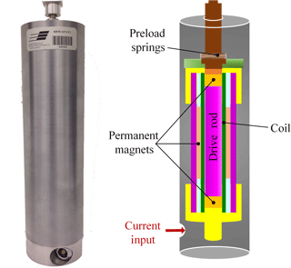
The experiments were performed on a magnetostrictive actuator (MFR OTY77, Etrema Products, Inc.) with stroke of ±50 µm. The actuator comprised two Terfenol-D material drive rods, preloaded by a compression bolt and a spring washer, and encapsulated by coils, and permanent magnets that provide essential magnetic bias for the actuator to operate in the linear region (Fig. 1). The actuator could provide a dynamic force up to approximately 1.1 kN in the 0–1250 Hz frequency range. The actuator was oriented vertically in a fixture, which could support the load. The loading fixture was designed with vertical guide rods to minimize the side loads and moment on the actuator. Up to five lead blocks (each weighing 5.5 to 5.8 kg) were used in the loading fixture and centered via the guiding rods, while the loading fixture alone weighed 4.2 kg. Different combinations of the blocks with fixture thus permitted experimental characterizations with loads ranging from 0 to 33 kg.
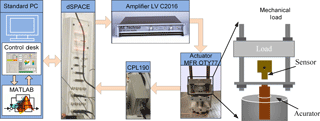
The actuator displacement was measured using a capacitive sensor (Lion Precision, model C23-C250) with resolution of 35.53 nm and bandwidth of 15 kHz. The excitation signal was synthesized in the dSPACE-ControlDesk platform and applied to the actuator drive coil through a power amplifier (LVC 2016, AE Techtron Inc). The actuator displacement response together with the applied input was acquired in the ControlDesk platform. A schematic of the experimental set-up is shown in Fig. 2. The experiments were conducted to characterize input-output properties under different operating loads (0–33 kg) and frequencies (1 to 150 Hz), including: (i) major-loop tests; (ii) minor-loop tests; and (iii) frequency response of the actuator. The experimental conditions and the results attained from each test are discussed in the following sub-sections.
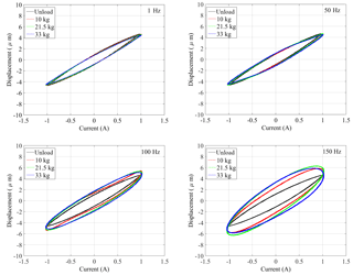
Figure 3Major-loop hysteresis characteristics of the magnetostrictive actuated system under operating loads (0–33 kg) and excitation frequencies (1–150 Hz).
2.2 Major-loop tests
The hysteresis nonlinearity of the actuated system was initially characterized through major loop tests under different loads and excitation frequencies. The measurements were performed under constant amplitude (1 A) harmonic excitations at different discrete frequencies (f=1, 50, 100 and 150 Hz). The experiments were conducted with unloaded as well as loaded actuator with different loads (10, 21.5 and 33 g). The excitation current and output displacement signals, acquired in the ControlDesk, provided the major-loop characteristics.
Figure 3, as an example, shows measured displacement-current (output-input) characteristics of the actuated system illustrating hysteresis major-loops under 1 A harmonic excitations. The results are presented for different discrete frequency excitations and operating loads, which show significant effect from the load. Furthermore, with the increase of the frequency, the delay effect becomes more evident at higher frequencies. The resonant frequency of the actuator also decreases considerably with increasing mass. The output displacement amplitude of the magnetostrictive actuated system thus shows more significant contributions of dynamics of the actuator under higher frequency excitations. Specifically, the displacement-current characteristics of the magnetostrictive actuator without load for different discrete frequency can also be described by rate-dependent PI model (Minorowicz et al., 2016) well by involving the input frequency in the play operator. However, the RDPI model is not capable of describing the situation with actuating loads especially under high frequency.
2.3 Minor loop tests
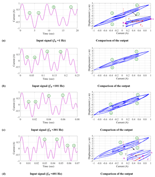
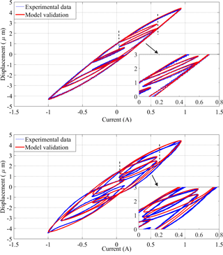
The minor-loop tests were performed to further explore hysteresis nonlinearity of the magnetostrictive actuated system coupled with nonlinear effects of the load and operating frequency. The measurements were performed under a complex harmonic excitation current v(t) of the form: , where a1 and a2 are amplitudes, q1 and q2 are frequency scale factors, and f0 is the fundamental frequency. Experiments were conducted considering four different fundamental frequencies (1, 101, 301 and 401 Hz), and constant amplitudes (a1=0.4428 A; a2=0.5535 A) and scale factors (q1=0.35; q2=0.1). The minor loop tests were limited to a fixed load, represented by the loading fixture attached to the actuator (mass = 4.2 kg).
Figure 4 illustrates excitation waveforms and output-input characteristics corresponding to the chosen fundamental frequencies (1, 101, 301 and 401 Hz). The measured results obtained under low frequency excitation (1 Hz) in Fig. 4a suggest that the minor-loops satisfy the congruency property (Mayergoyz, 1991). The output delay of the magnetostrictive actuated system can be described by the classical hysteresis modeling method. Under higher frequency excitations, the minor-loops tend to cross-over in some special points, indicated by encircled numbers 1 to 4 in Fig. 4b to d. The minor-loops at higher excitation frequencies thus do not satisfy the congruency property, and the delay effect due to the mechanical load also change the basic property of hysteresis, which should be considered in the modeling method. The details are further discussed in Sect. 3.
2.4 Magnitude and phase response tests
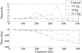
The frequency response characteristics of magnetostrictive actuated system were measured under different loads to further study the delay load effect on system dynamics. The measurements were performed with the unloaded as well as loaded actuator subject to several discrete harmonic excitations in the 1 to 500 Hz frequency range with constant amplitude of 0.5 A. The measured data were analyzed to obtain magnitude and phase response characteristics of the actuator for different loads. The magnitude response at different frequencies is normalized with respect to the displacement response at 1 Hz. Figure 5 illustrates normalized magnitude and phase responses of the unloaded actuator and the loaded actuator under three different loads (4.2, 10 and 21.5 kg). The results suggest the following dynamic features of the magnetostrictive actuated system:
The magnitude and phase responses suggest a high-order dynamic system feature, while the actuator's natural frequency decreases with the load. The response is thus affected by the actuator's resonance particularly under higher operating loads. This is also evident from considerable higher amplitude of the loaded actuator displacement under higher frequency excitations, also evident in Fig. 3.
Increasing the actuator load yields substantially higher delay, which is further augmented with increase in excitation frequency. This is also evident from the major loops presented in Fig. 3.
3.1 Discussions on Measured Nonlinearity characteristics
The results obtained from the major- and minor-loop tests, and the frequency responses tests suggest highly complex nonlinearities in the input-output characteristics of the system. These clearly show the hysteresis nonlinearity coupled with input rate-dependent and load-dependent delay effects. A modified PI hysteresis model with load-dependent delay is thus formulated to describe the hysteresis nonlinearity coupled with the working nonlinearities. To formulate the model, the observed nonlinearity in the output of the magnetostrictive actuated system is further examined considering the congruency property. The classical definition in Mayergoyz (1991) and Brokate and Sprekels (1996) states that systems with hysteresis have a persistent memory of the past that remains after the transients have subsided. The output y(t) of the system depends on the path followed by the input v(t) but not on the rate at which it traverses the path. The definition of this property is thus briefly discussed below.
Hysteresis congruency property (Mayergoyz, 1991): “For the pure hysteresis nonlinearity, all minor loops resulting from back and forth input variations between the same two consecutive extrema have equal vertical chords (output increments) for the same input values”. According to Madelung's rules, following three properties should be satisfied, which can be illustrated from the minor-loop test results in Fig. 4.
Any curve Γ1 emanating from a turning point A (extrema) of the input-output graph is uniquely determined by the coordinates of A (Fig. 4a).
If any point B on curve Γ1 becomes a new turning point, the curve Γ2 originating at B then leads back to the point A.
If the curve Γ2 is continued beyond point A it would coincide with continuation of curve Γ which led to point A prior to traversing Γ1−Γ2 cycle (minor loop).
As shown in Fig. 4a, the minor-loop characteristics satisfy the above-stated congruency properties under low frequency excitation. The nonlinearity existing between the input and output of magnetostrictive actuated system with load can thus be treated as classical hysteresis in such working condition. This nonlinearity of the magnetostrictive actuated system at a low frequency condition can be accurately described by the classical PI model, which have been widely reported (Chen and Hisayama, 2008). The minor-loops corresponding to same extremum values of input at higher excitation frequencies (101, 301 and 401 Hz), presented in in Fig. 4b–d, however, are non-congruent and do not satisfy the Madlung's rules. These suggest that nonlinear output-input properties of the magnetostrictive actuated system under such working conditions cannot be adequately described by classical hysteresis alone, and the available hysteresis modeling methods may not be applicable.
From the measured major- and minor-loops and frequency response characteristics (Figs. 3 to 5), it is evident that the system's output is strongly coupled with the working condition related to load, and is further affected by the input frequency. The coupled effect of working condition-induced nonlinearities may be described by the delay related to the load. A load-dependent based hysteresis modeling method is thus presented in following section.
3.2 Classical PI hysteresis model
The hysteresis nonlinearity in the magnetostrictive actuator is initially described by the PI model. It should be noted that the hysteresis nonlinearity observed for the unloaded actuator at a low frequency is not limited to PI model alone and it could be modelled using different approaches such as Preisach model, Bouc-Wen model and Duhem model. The PI model is employed in this study as a mere illustration to show the integration of load-dependent delay function. Moreover, the PI model likely offers better real-time implementation potential for compensations considering its continuous nature and analytic invertibility.
In this subsection, the classical PI model is presented, which is constructed by play operator Fr[v](t) with discrete thresholds r. As shown in Eq. (1),
v(t) is the input, p0 a positive constant, and p(r) is a given density function and the play operator Fr[v] is given by:
For with , where is a partition within [0,tE] such that the function v(t) is monotone on each of the sub-intervals [titi+1].
3.3 PI hysteresis model with load-dependent delay
The load-dependent delay effect in the PI model output u(t) can be introduced in the following manner:
where y(t) is output of the magnetostrictive actuated system incorporating the load-delay effect attributed to operating load. D[u](t) is a delay operator defined in Eq. (4), which involves the output of Prandtl-Ishlinskii model.
For the load-delay effect, as observed for the magnetostrictive actuated system, τ(m) is designed as a function of load mass m to show the dependence property. The hysteresis with load-dependent delay formulations in Eqs. (3) and (4) constitutes a cascade structure, as shown in Fig. 6.
The proposed modified based PI model with load-dependent delay can thus be expressed as:
Remark: In order to accurately describe the nonlinear load-dependent feature, the delay τ is designed as a function of the load expressed in terms of the mass (m). It may also be designed as function of other parameters that affect loading property such as stiffness.
4.1 Numerical implementation of the proposed model
For numerical implementations of the modified based PI model with load-dependent delay, a time-discrete expression is used, given by:
where τk denotes the load-delay operator, u[v] is the Prandtl-Ishlinskii model output, which is written as the discrete form:
where pi denotes the weights of the play operator; are play operators corresponding to the threshold ri and n is number of the play operators used in the model.
In this subsection, an identification method is introduced for identifying parameters of the proposed model. The method involves two sequential steps: (i) identifications of the PI hysteresis model parameters, the thresholds ri and density weights pi (ii) identification of load-delay operator parameters τ (m).
4.2 Hysteresis parameter identification
In the first stage, the thresholds ri and density weights pi are identified for the PI model, where the thresholds ri are selected as:
and r0=0.
In Eq. (8), n is number of operators considered in the model. The current is designed as an exponentially decreasing sine function. As an illustration, a current signal of the form is chosen for the first stage identification test.
The weights can be determined through solutions of the following constrained quadratic minimization function:
where is the vector of weights. is the play operators vector, where is known output of the unloaded magnetostrictive actuator under the selected input signal. Nonlinear least-square minimization toolbox in MATLAB is employed to solve for Λ. Table 1 lists the identified model parameters, ri and pi, while a total of 31 operators were considered in the identification test.
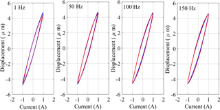
Figure 8Comparisons of major-loop output-input responses between the proposed model and the measured data without load. (Frequencies in 1, 50, 100 and 150 Hz and excitation amplitude 1 A, blue line – measured data; red line – proposed model.)
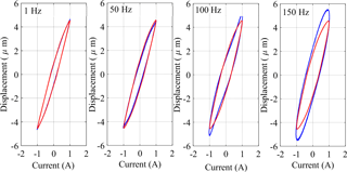
Figure 9Comparisons of major-loop output-input responses between the proposed model and the measured data with load (4.2 kg). (Frequencies in 1, 50, 100 and 150 Hz and excitation amplitude 1 A, blue line – measured data; red line – proposed model.)
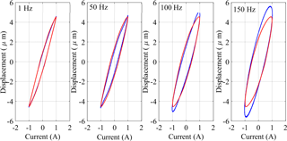
Figure 10Comparisons of major-loop output-input responses between the proposed model and the measured data with load (16 kg). (Frequencies in 1, 50, 100 and 150 Hz and excitation amplitude 1 A, blue line – measured data; red line – proposed model.)
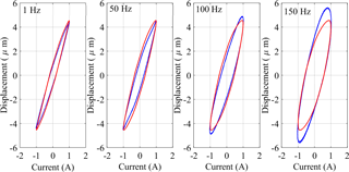
Figure 11Comparisons of major-loop output-input responses between the proposed model and the measured data with load (21.5 kg). (Frequencies in 1, 50, 100 and 150 Hz and excitation amplitude 1 A, blue line – measured data; red line – proposed model.)
4.3 Load dependent delay operator parameter identification
Consider the Fourier expression of the error signal in the frequency domain as a function of the load-dependent delay τ(m):
The phase due to delay can be expressed as:
The load-delay corresponding to each load mass is subsequently identified through minimization of terror between the measured and model phase responses. The measured phase response, however, revealed slight phase lag at the low frequency of 1 Hz, which was consistent for all the loads considered during measurements. This phase lag can be attributed to the hysteresis effect alone, and it is considered as a bias and was subtracted from the phase responses measured over the entire frequency range for each load case. It should be further noted that phase response of the unloaded actuator also increases slowly with increasing frequency, which can be attributed to the load-delay and dynamic effect due to small mass of the Terfenol-D rods. The load-dependent delay τ(m) corresponding to each load was subsequently obtained from solutions of the least square minimization problem:
where ψi(mωi) are the adjusted measured phase lags corresponding to load mass m and frequency ωi and k is the number of discrete frequencies considered. The frequency range was chosen so as to reduce the contributions of resonant dynamics of the loaded actuators. From the measured responses, it is evident that the actuator undergoes resonance near 350, 275 and 200 Hz, respectively, when subject to 4.2, 10 and 21.5 kg loads. The resonant frequency was substantially lower under 33.5 kg. The solutions of the error minimization problem were thus limited to 150 Hz, while excluding the 33.5 kg case.
Table 2 summarizes the load-dependent delays identified for each load case, including the unloaded actuator. A cubic polynomial regression function in load mass was subsequently identified to describe the load-dependent delay:
The above regression function showed very good fit with the identified time-deal for the range of load considered (r2=1).
Using the proposed hysteresis model with time-delay and the identification parameter method introduced, the modeling method can describe the magnetostrictive actuated system with load accurately. The comparison with the experiment measured data in the major loops is given in Fig. 7, which can illustrate the effectiveness of the proposed modeling and parameter identification methods well.
4.4 Model Verifications
The effectiveness of the proposed modeling method is illustrated by comparing the model results with experimental data acquired from the major loop and minor loop tests for the magnetostrictive actuated system with different loads. The model validity is initially examined under exponentially decaying harmonic inputs at different frequencies. In order to validate the suitability of the proposed modeling method, one parameter ModelErr is used, which is defined as
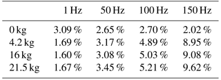
where Ex denotes the displacement output of the magnetostrictive actuated system, Mo denotes the output of the proposed load-delay based PI model. ModelErr is used to reflect the accuracy of the modeling method under different loads and frequencies. For this magnetostrictive actuated system, with frequencies 1–150 Hz, loads 0, 4.2, 16 and 21.5 kg, the values of ModelErr are given in Table 3.
Figures 8–12 presents the comparisons of major loops output-input characteristics predicted from the modified PI model with load-dependent delay with the measured data acquired for four different loads (0, 4.2, 16 and 21.5 kg). The comparisons are illustrated under 1 Amp harmonic excitations at different frequencies in the 0 to 150 Hz range. The results suggest very good agreements between the model and measured results obtained in the absence of load (0 kg), irrespective of the excitation frequency considered in the study. The peak difference between the displacement response of the model and measured data was below 10 %, which occurred at the highest frequency considered (150 Hz). The comparisons also show very good agreements between the proposed model and experimental results for loads of 4.2, 16 and 21.5 kg under low frequency excitations, while deviations between the two are evident at higher frequencies. The deviations between the modified PI model with load-dependent delay results and the experimental data increase with increasing frequency. The observed deviations are attributable to two important factors. Firstly, the proposed modified PI model is based on classical Prandtl-Ishlinskii model, which is expected to yield greater errors with increasing rate of input. The peak deviation between the displacement response of the modified PI model with load-dependent delay and measured data was below 2 % when the actuator was subject to 21.5 kg load and excitation at 1 Hz. The peak deviation under the same load increased to 3.45 % at 50 Hz, 5.21 % at 100 Hz and 9.62 % at 150 Hz. The comparisons thus suggest that proposed modified PI model with load-dependent delay can reflect the load-dependent delay property accurately in a wide range of operating loads at lower excitation frequencies. The deviations under higher frequency excitations could in-part be reduced by integrated the load-delay model to a rate-dependent Prandtl-Ishlinskii incorporating dynamic density or threshold functions.
Secondly, addition of load to the actuator leads to substantially lower natural frequency of the system and thereby exhibits strong dynamic effect at higher excitation frequencies. The magnetostrictive actuator, considered in the study, revealed resonance near 200 Hz when loaded to 21.5 kg, and near 275 Hz under 16 kg load. The actuator's displacement response increased with increasing frequency beyond 80 Hz under 21.5 kg load and beyond 100 Hz under 16 kg load, as seen in Fig. 5. Relatively larger deviations observed between the model and measured responses under inputs at 100 and 150 Hz are thus in-part caused by the dynamic behaviour of the load-actuator system and the resonance, which is not considered in the proposed PI model with load-dependent delay. In practical situations, it would not ne likely to operate the actuator near its resonance since it could cause rapid damage of the actuator. Further efforts, however, would be desirable by considering load-actuator system dynamics in the model for better response predictions.
Figure 12 further compares the model responses in the frequency range (0–150 Hz), where the minor loop identification results with load as 4.2 kg, and the input signal is chosen as with f0=1 and f0=401.
From the results shown in Figs. 8–12, the proposed modeling method with load delay can reflect the load-dependent property accurately in a wide load range and operating frequency. However, it is also should be mentioned that the model accuracy becomes worse with the increasing of the input frequency, since the magnitude response of the actuated system varies with the increase of the input frequency. When the input frequency approaches the natural frequency of the actuated system, the actual output of magnetostrictive actuated system will increase quickly, and the experiment results show in Fig. 5 also show the feature. Technically, the input frequency won't be chosen near the natural frequency of the actuating system, since the output increases to the unexpected value, which will damage the actuating system severely. Therefore, the magnitude response of the actuating system can be used as the reference for the working condition, especially the choice of the input frequency with variable loads. The proposed model in this study does not cover the feature of the magnitude change, and it will be the further problem addressed in the future work.
The measured output response of the magnetostrictive actuated system revealed more complex features in the presence of a mechanical load, suggesting coupled nonlinear effects of hysteresis and load-dependent delay. The displacement magnitude and phase responses suggested a high-order dynamic system feature. For a given current excitation, the displacement magnitude of the actuator at higher frequency increased with increasing mechanical load, which was attributed to lower resonant frequency of the actuating system with load, and higher delay. The measured major loops revealed substantially higher delays with the increase of actuating load, which was further augmented with increase in excitation frequency. The minor-loop properties, on the other hand, were observed to be non-congruent, particularly at higher frequencies, suggesting that the delay effect is coupled with hysteresis nonlinearity and change the system output characteristics. The coupled nonlinear effects of mechanical load and hysteresis could be effectively characterized by the classical Prandtl-Ishlinskii model integrating a load-dependent delay operator. Comparisons of the model results with the measured data suggested that the proposed modeling method could accurately describe the load-dependent delays together with the hysteresis nonlinearity over a wide range of mechanical loads at frequencies below the primary resonant frequency.
Data can be made available upon request. Please contact Ying Feng (zhdfengying@gmail.com).
The authors declare that they have no conflict of interest.
The work was partially supported by the Funds for National Key research and
Development Program of China (2017YFB1302302), Science Foundation of Science
and Technology Planning Project of Guangdong Province, China (2017A010102004)
and The University Key Laboratory Program of Guilin University of Electronic
Technology (GXZDSY2016-02).
Edited by: Marek
Wojtyra
Reviewed by: two anonymous referees
Braghin, F., Cinquemani, S., and Resta, F.: A model of magnetostrictive actuators for active vibration control, Sensor Actuat. A-Phys., 165, 342–350, 2011.
Brokate, M. and Sprekels, J.: Hysteresis and phase transitions, Applied mathematical sciences, Vol. 121, Springer, New York, 1996.
Cao, S. Y., Wang, B. W., Zheng, J. J., Huang, W. M., Sun, Y., and Yang, Q. X.: Modeling dynamic hysteresis for giant magnetostrictive actuator using hybrid genetic algorithm, IEEE T. Magn., 42, 911–914, 2006.
Chen, W. M. and Liu, T. S.: Modeling and experimental validation of new two degree-of-freedom piezoelectric actuators, Mechatronics, 23, 1163–1170, 2013.
Chen, X. and Hisayanna, T.: Adaptive sliding-mode position control for piezo-actuated stage, IEEE T. Ind. Electron., 55, 3927–3934, 2008.
Chen, X. and Ozaki, T.: Adaptive control for plants in the presence of actuator and sensor uncertain hysteresis, IEEE T. Automat. Contr., 56, 171–177, 2011.
Chen, X. and Su, C. Y.: Adaptive control for ionic polymer-metal composite actuators, IEEE T. Syst. Man. Cy. A, 46, 1468–1477, 2016.
Coleman, B. D. and Hodgdon, M. L.: On a class of constitutive relations for ferromagnetic hysteresis, Arch. Ration. Mech. An., 99, 375–396, 1987.
Feng, Y., Hu, Y. M., Rabbath, C. A., and Su, C. Y.: Robust adaptive control for a class of perturbed strict-feedback non-linear systems with unknown Prandtl-Ishlinskii hysteresis, Int. J. Control, 81, 1699–1708, 2008.
Jani, J. M., Leary, M., Subic, A., and Gibson, M. A.: A review of shape memory alloy research, applications and opportunities, Mater. Design, 56, 1078–1113, 2014.
Kuhnen, K.: Modeling, identification and compensation of complex hysteretic nonlinearities a modified Prandtl-Ishlinskii approach, Eur. J. Control, 9, 407–418, 2003.
Li, D. W., Li, D. W., Yang, Z. S., He, Z. B., Rong, C., and Su, W. P.: Dynamic model of a giant magnetostrictive actuator system with time delay, Aer. Adv. Eng. Res., 62, 236–240, 2016.
Li, Z., Su, C. Y., and Chai, T. Y.: Compensation of hysteresis nonlinearity in magnetostrictive actuators with inverse multiplicative structure for preisach model, IEEE T. Autom. Sci. Eng., 11, 613–619, 2014.
Liu, H. F., Jia, Z. Y., Wang, F. J., and Zong, F. C.: Research on the constant output force control system for giant magnetostrictive actuator disturbed by external force, Mechatronics, 22, 911–922, 2012.
Liu, Y. F., Li, J., Hu, X. H., Zhang, Z. M., Cheng, L., Lin, Y., and Zhang, W. J.: Modeling and control of piezoelectric inertia-friction actuators: review and future research directions, Mech. Sci., 6, 95–107, 2015.
Mayergoyz, I. D.: Mathematical models of hysteresis, Springer-Verlag, New York, 1991.
Minorowicz, B., Leonetti, G., Stefanski, F., Binetti, G., and Naso, D.: Design, modelling and control of a micropositioning actuator based on magnetic shape memory alloys, Smart Mater. Struct., 25, 075005, https://doi.org/10.1088/0964-1726/25/7/075005, 2016.
Nguyen, M. L., Chen, X., and Yang, F.: Discrete time quasi sliding mode control with prescribed performance function and its application to piezo-actuated positioning systems, IEEE T. Ind. Electron., 65, 942–950, 2018.
Niu, M. Q., Yang, B. T., Yang, Y. K., and Meng, G.: Dynamic modelling of magnetostrictive actuator with fully coupled magneto-mechanical effects and various eddy-current losses, Sensor Actuat. A-Phys., 258, 163–173, 2017.
Rongge, Y., Bowen, W., Cao, S. Y., and Huang, W. M.: Investigation of current dependencies of displacement under variable load for giant magnetostrictive actuators, IEEE T. Magn., 41, 1528–1531, 2005.
Smith, R: Smart Material Systems: Model Development, SIAM, Philadelphia, PA, 2005.
Song, G., Zhao, J. Q., Zhou, X. Q., and de Abreu-Garcia, J. A.: Tracking control of a piezoceramic actuator with hysteresis compensation using inverse Preisach model, IEEE-ASME T. Mech., 10, 198–209, 2005.
Su, C. Y., Feng, Y., Hong, H., and Chen, X.: Adaptive control of system involving complex hysteretic nonlinearities: a generalised Prandtl-Ishlinskii modelling approach, Int. J. Control, 82, 1786–1793, 2009.
Tan, X. B. and Baras, J. S.: Modeling and control of hysteresis in magnetostrictive actuators, Automatica, 40, 1469–1480, 2004.
Valadkhan, S., Morris, K., and Shum, A.: A new load-dependent hysteresis model for magnetostrictive materials, Smart Mater. Struct., 19, 125003, https://doi.org/10.1088/0964-1726/19/12/125003, 2010.
Wang, Y. J., Zhao, X. Y., Jiao, J., Liu, L. H., Di, W. N., Luo, H. S., and Or, S. W.: Electrical resistance load effect on magnetoelectric coupling of magnetostrictive/piezoelectric laminated composite, J. Alloy. Compd., 500, 224–226, 2010.
Zhang, Z., Mao, J. Q., and Zhou, K. M.: Experimental characterization and modeling of stress-dependent hysteresis of a giant magnetostrictive actuator, Sci. China Technol. Sci., 56, 656–665, 2013.
Zheng, J. J., Cao, S. Y., Wang, H. L., and Huang, W. M.: Hybrid genetic algorithms for parameter identification of a hysteresis model of magnetostrictive actuators, Neurocomputing, 70, 749–761, 2007.
Zhu, Y. C., Yang, X. L., and Wereley, N. M.: Research on hysteresis loop considering the prestress effect and electrical input dynamics for a giant magnetostrictive actuator, Smart Mater. Struct., 25, 1–16, 2016.


