the Creative Commons Attribution 4.0 License.
the Creative Commons Attribution 4.0 License.
 | 19 Oct 2026
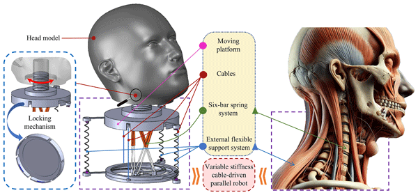
Design and analysis of a novel cable-driven parallel robot with variable stiffness and rigid–flexible coupling
Yutong Wu
Xinlei Xiao

Haochen Wang
Da Song
This study presents a novel cable-driven parallel robot integrated with rigid–flexible coupling and a variable stiffness system, specifically designed to replicate the motion characteristics of the human cervical spine. Kinematic control of the robot is achieved by establishing a functional relationship between its configuration space and actuation space, where cable length variations are constrained within ±40 mm. Furthermore, this work explores static and dynamic modeling methodologies, highlighting their critical role in evaluating the robot's performance under operational poses. A detailed analysis is conducted to investigate the synergistic effects between the rigid–flexible coupling structure and the variable stiffness system. By incorporating adjustable stiffness parameters, a dynamic model is developed to reveal the robot's behavioral characteristics under different poses. Simulation results demonstrate that the robot achieves a maximum bending angle of 30° under cable tensions from 0 to 80 N, while its operational stiffness can be dynamically modulated from 3900 to 4700 N m−1 (with a tuning bandwidth of up to 100 %). These quantitative findings confirm the validity of the proposed model and illustrate the capabilities of the robot in flexible bending motion and stiffness regulation, providing a valuable reference for the design and analysis of other cable-driven flexible mechanisms.
- Article
(9726 KB) - Full-text XML
- BibTeX
- EndNote


With the rapid advancement of industrial technology, human–robot collaboration has become a crucial driver of technological innovation and productivity enhancement (Cao et al., 2025; Yin et al., 2026). The continuous progress in robotics has significantly liberated human labor, reducing the burden of monotonous and strenuous physical tasks. Furthermore, robotics has demonstrated extensive application potential and exceptional value in industrial manufacturing, healthcare, education, and training, as well as in specialized scenarios. As an important direction in robotics research, bionics provides a solid theoretical foundation and technical support for building flexible and efficient robotic systems by mimicking biological structures and functions (Liu et al., 2022; Wang et al., 2024). In the field of humanoid robotics, research on structural design and motion control is particularly critical (Ding et al., 2022). Specifically, bio-inspired designs for flexible human body parts, such as the human cervical spine, leverage their characteristics of multiple degrees of freedom (DOF) and high-precision motion control to exhibit outstanding advantages in performing complex tasks (Giannaccini et al., 2018). These designs open up new directions and technological pathways for the research and application of humanoid robots.
In recent years, bionic human neck robots have gained widespread attention and undergone in-depth research in the fields of bionics and robotics (Yang et al., 2020). As an essential component of the human body, the neck plays a crucial role in maintaining balance, performing complex tasks, and perceiving the external environment due to its unique flexibility and multi-degree-of-freedom motion characteristics (Kang et al., 2013). The cervical spine consists of seven vertebrae, and through the coordinated action of joints, ligaments, and muscles, it is capable of executing diverse and highly flexible movements, including flexion, extension, lateral bending, and rotation (Bhalkikar et al., 2024). Studies have shown that the unique structure of the cervical spine, along with the coordination between adjacent joints, enables precise and agile movements (Thorapalli Muralidharan et al., 2026). In biomechanics research, finite element modeling and experimental analysis have revealed the motion characteristics of the cervical spine under various loading conditions, while also highlighting the critical role of muscles and ligaments in maintaining stability during movement (Kuo et al., 2019). In the design of bionic neck robots, the currently developed structures are primarily classified into serial and parallel mechanisms. Serial mechanisms are widely applied due to their high flexibility and ease of control, whereas parallel mechanisms are favored for their higher rigidity and lower inertia, making them suitable for specific scenarios (Song et al., 2023). Parallel mechanisms offer more distinct advantages in handling high loads and low inertia, which are key factors in simulating human neck movements (Renda et al., 2012; Song et al., 2025).
The ASIMO robot by Honda and the HRP-2 robot both feature a serial neck structure with two degrees of freedom (pitch and roll), enabling basic head movements (Liu et al., 2023; Song et al., 2024). To achieve more complex motion capabilities, the Dav robot, Albert Hubo, and iCub robot have expanded their serial neck design by adding a yaw degree of freedom, further enhancing the movement abilities (Jones and Walker, 2006). The four-degrees-of-freedom serial neck design proposed in Falkenhahn builds upon the three existing degrees of freedom and adds a nodding freedom, resulting in more flexible movement (Falkenhahn et al., 2015). In contrast to serial structures, parallel neck structures typically follow the principles of parallel manipulators, allowing for pitch and roll movements, while yaw motion is achieved through additional mechanisms (Trivedi et al., 2008). For example, the design of the SAYA robot combines a spring spine with pneumatic artificial muscles, bringing head movements closer to the functionality of human muscles, though the sensitivity still needs improvement (Camarillo et al., 2008). The iCub robot has further explored parallel neck structures, including a combination of a spring spine and cables, as well as a parallel manipulator with three degrees of freedom. The latter design enhances stability through a central passive spherical support. The head structure of the James humanoid robot is similar to the first parallel neck design of the iCub robot. Additionally, the literature introduces a parallel neck design based on cable-driven elastic limbs and passive body parts (Falkenhahn et al., 2017; Renda et al., 2018). This innovative structural layout enhances the performance and adaptability of the bionic neck. However, the design still lacks sufficient compliance to simulate the bending motion of the cervical spine, failing to fully replicate the motion characteristics of the human neck.
In summary, while existing neck robot designs have achieved improvements in motion performance and adaptability, they are still constrained by inherent limitations. Parallel neck designs enhance motion capabilities but fail to adequately address the compliance required for bending motions, preventing them from fully replicating the flexibility and multi-degree-of-freedom movements of the human cervical spine. Although some designs have increased the number of degrees of freedom and introduced greater complexity, issues of sensitivity and biomimicry remain unresolved.
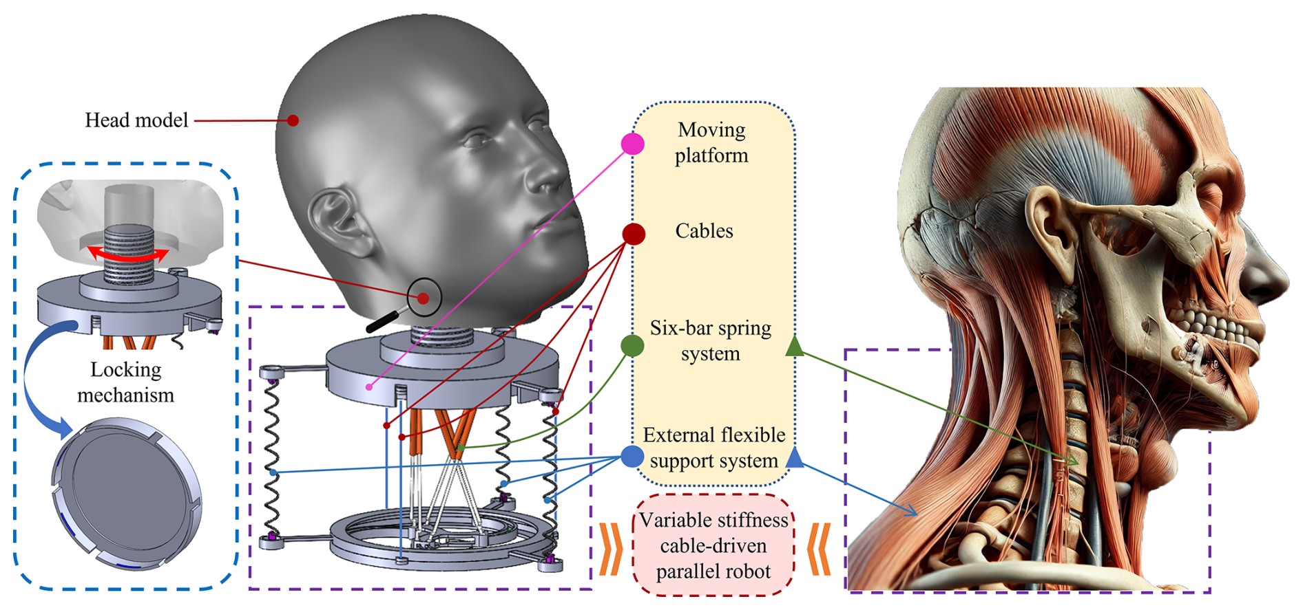
Figure 1Design framework of the cable-driven, rigid–flexible coupled variable stiffness parallel robot for the cervical spine.
Based on an in-depth analysis of biomimetic human cervical robots and key functional requirements, this paper proposes a novel stiff–flexible coupling variable stiffness parallel robot (as shown in Fig. 1). The robot uses a cable-driven unit that combines rigid and flexible components (Sadati et al., 2021; Yang et al., 2021). It also incorporates a variable stiffness system that simulates the muscle adjustment function of the human cervical spine. This design allows the robot to more closely resemble the motion of the human cervical spine and meets human anatomical movement requirements. Compared to the cable-driven parallel robot with a spring-based spine designed by Gao and Song, the proposed robot features an evaluated workspace distribution for its rigid–flexible coupling mechanism (Grazioso et al., 2019). By applying torque balance theory based on Newton's second law and the conservation of angular momentum, it redefines the range of bending and azimuth angles (Luo et al., 2024; Yang et al., 2024). This improvement allows for a more accurate simulation of the motion characteristics of the human cervical spine. In addition, inspired by the working mechanisms of human cervical muscles and ligaments, the robot features an innovative rotational structure (Godage et al., 2015). This structure adjusts the radius of the external flexible support system through rotational motion. As a result, it dynamically regulates the cable driving force and alters the robot's overall stiffness characteristics. Consequently, the neck structure proposed in this study seeks to optimize both motion freedom and compliance, improve sensitivity, and more accurately mimic the natural movement of the human cervical spine, with the goal of overcoming the limitations inherent in current designs.
The structure of this paper is arranged as follows: Sect. 2 provides a brief introduction to the overall structure of the stiff–flexible coupling variable stiffness parallel robot and analyzes its general kinematic model; Sect. 3 delves into the static and dynamic characteristics of the robot and establishes a classical dynamics model; Sect. 4 verifies the effectiveness of the design through simulations and evaluates the stiff–flexible coupling and variable stiffness system; Sect. 5 presents a critical analysis and discussion of the results; finally, Sect. 6 summarizes the main research findings of this paper.
2.1 Configuration design of the parallel robot
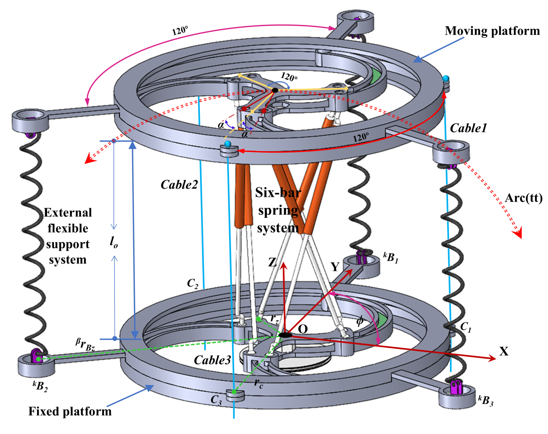
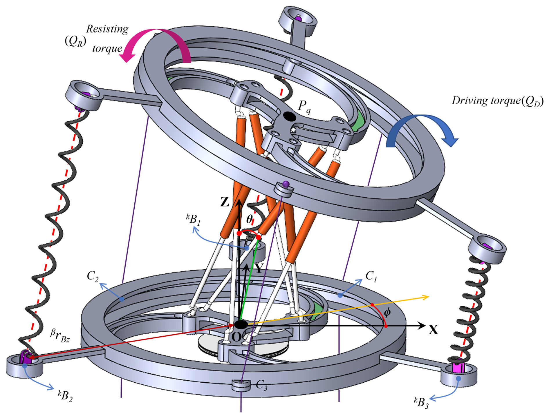
Figure 2 illustrates the configuration design of a cable-driven, rigid–flexible coupling parallel robot with variable stiffness. The robot comprises five main components: the moving platform, the fixed platform, the six-bar spring system, the rotating mechanism, and the external flexible support system. It is driven by three cables with negligible mass and diameter. The structural design incorporates a rigid–flexible coupling structure, where the six-bar spring system mimics the function of the human cervical spine, and the external flexible support system simulates the neck muscles, improving the robot's compliance and adaptability during motion. In operation, the moving platform is driven by cables, while the rotating mechanism adjusts the radius of the external flexible support system to simulate the force exerted by the neck muscles, thereby enabling efficient modulation of the robot's stiffness (covering kinematic analysis, dynamic analysis, and simulation analysis).
2.2 General kinematic analysis of the parallel robot
The rigid–flexible coupling parallel robot with variable stiffness has three DOF, enabling bending and stretching motions similar to the human cervical spine. Cables u (where u=1, 2, 3) pass through points C1, C2, and C3 on the fixed platform and are connected to cable holes on the moving platform, as shown in Fig. 2. The robot's motion is driven by motors that control the cables. Note that although the physical prototype can theoretically execute 3-DOF motion, in this study, the distance l0 is assumed constant to focus on the 2-DOF bending performance.
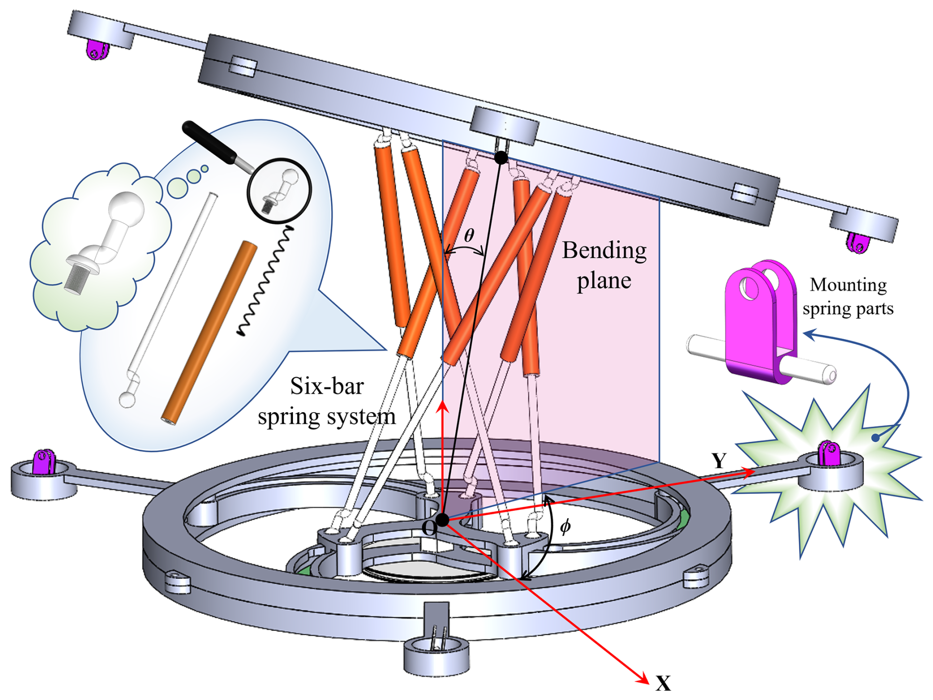
In Fig. 3, the six-bar spring system ensures structural stability between the fixed and moving platforms and provides necessary bending compliance. The system is fixed to a rotating structure, with an angle adjustment range of 0 to 60°. A motor drives the transmission components at the bottom of the rotating structure, adjusting the variable radius βrBz of the external flexible support system to control stiffness.
This design allows the robot to exhibit different stiffness levels in various operating environments, enhancing its adaptability.
Figures 2 and 3 illustrate the global coordinate system established on the fixed platform, with its origin O located at the geometric center of the platform. The radius of the cable hole is denoted by rc, and the radius of the installation point for the six-bar spring system is denoted by rz. These parameters allow for the precise determination of the coordinates of each installation point within the coordinate system. This serves as the foundation for subsequent kinematic and dynamic analyses. The establishment of this coordinate system is crucial for understanding the relationship between the parallel robot platform and its connected components, as well as for analyzing the mechanical behavior under different operating conditions.

As shown in Fig. 4, the variable stiffness system adjusts flexibility by modifying the radius δrz of the external flexible support system. The variable radius δrz is determined by the rotation angle β of the rotating structure through the function frotate, and combined with the fixed radius rB, the actual radius rBz of the external flexible support system is calculated, allowing the coordinates of the three fixed points of the system to be determined.
Here, δrz is the variable radius of the slide rail and kB1, kB2, and kB3 are the external flexible support system fixed point coordinates.
Equations (1), (2), and (4) describe the coordinates of the cable hole, the installation points of the six-bar spring system, and the fixed points of the external flexible support system, respectively. Based on the posture of the parallel robot shown in Fig. 3, setting the bending angle θi and azimuth angle ϕi allows the configuration space qi to be determined.
From the state of the configuration space qi, the actuation space Δl of the parallel robot can then be derived.
The configuration space qi and the actuation space Δl are related through the homogeneous transformation matrix RTP (Liu et al., 2020). Based on the configuration space definition, the rotation matrix Rq (ϕi, θi) and the actuator end position Pq (ϕi, θi) can be determined. When the actuation space value is zero (i.e., the length change of all three cables is zero), both the bending angle θi and the azimuth angle ϕi are zero, indicating that the parallel robot's driving cables are pre-tensioned, as illustrated in Fig. 2. This represents the initial pre-tensioned state of the robot, where the distance between the moving platform and the fixed platform is lo. To establish a simplified yet effective kinematic model, it is assumed that the three actuation cables are controlled synchronously during main bending motions to maintain constant overall length along the central coupling axis, ensuring that the distance between Pq and point O remains constant at lo. The axial length variation of the flexible spring elements is primarily utilized for internal stiffness modulation rather than primary kinematic positioning.
During motion, the actuator end Pq (ϕi, θi) moves along the arc trajectory Arc(tt) shown in Fig. 2, due to the combined effect of the cable-driven six-bar spring system and the external flexible support system. The arc's center is located at the origin O of the global coordinate system, ensuring that the distance between Pq and point O remains constant at lo. From this characteristic, the mathematical expressions for the rotation matrix Rq (ϕi, θi) and the actuator end position Pq (ϕi, θi) can be derived (Ma et al., 2021).
Here, Rq is rotation matrix and Pq is actuator end matrix.
Based on the configuration space qi, the rotation matrix between the moving platform and the fixed platform, as well as the expression for the actuator end position in the global coordinate system, can be obtained from Eqs. (6) and (7) (Shao, 2015). By substituting these expressions into Eqs. (7) and (8), the homogeneous transformation matrix RTP, which describes the relationship between the moving platform and the fixed platform, can be derived.
Here, RTP is homogeneous transformation matrix.
When the parallel robot is in its initial state, the actuation space state is zero. At this point, based on the definition of Eq. (8), the homogeneous transformation matrix takes on a specific form.
Here, RTP is initial state homogeneous transition matrix.
Using the homogeneous transformation matrix RTP from Eq. (9), the actuation space Δl of the parallel robot can be further calculated. By controlling the changes in cable length through Δl, the motion of the parallel robot can be driven. Since RTP is a 4 × 4 matrix, when converting the point positions on the platform to the global coordinate system, the hole position coordinates in Eqs. (1), (2), and (4) need to be expressed in a 4 × 1 vector format, as shown in Eq. (11).
A function G is defined to describe the mapping relationship between the configuration space qi and the actuation space Δl. This function converts parameters from the configuration space into changes in the actuation space. This enables precise control of the parallel robot's driving cable lengths. By setting the parameters of the configuration space qi and applying function G, the changes in cable length can be determined. By accurately controlling these changes, the desired motion posture of the parallel robot can be adjusted.
The function G in Eq. (12) provides a new method for analyzing the kinematics of the parallel robot, especially for the kinematic modeling of bio-inspired human cervical parallel robots. Using this function G, the mapping function A from the actuation space Δl to the configuration space qi can be further derived. By precisely controlling the cables, the parallel robot's motion posture within the workspace can be adjusted, ensuring that the actuator's end effector reaches the designated target point.
3.1 Static analysis
Based on the kinematics of the rigid–flexible coupling variable stiffness parallel robot, the specific posture of the robot during motion can be determined through the mapping function G from the configuration space qi to the actuation space Δl. When the robot reaches a specific posture, its static behavior can be analyzed to examine the forces acting on the components during motion. When the robot is in the bent state shown in Fig. 5 and remains stationary, the driving torque applied by the cables balances the resistive torque generated by the six-bar spring system and the external flexible support system. By applying the principles of torque and force equilibrium (based on Newton's laws of motion and the conservation of angular momentum) and force equilibrium theory (derived from Newton's first and second laws), a detailed analysis of the forces on the cables in the stationary state can be conducted.
By combining the homogeneous transformation matrix defined in Eq. (9) with the coordinates of each point in Eqs. (1), (2), and (4), the lengths of the driving cables, the six-bar spring system, and the external flexible support system can be calculated. Additionally, as the robot moves, the length variations of these systems can be obtained for further analysis of their dynamic response characteristics.
Here, do is initial length of six-bar spring system.
In Eq. (14), when the parallel robot is in the zero actuation space state, do represents the initial length of each push rod in the six-bar spring system, and σ is the angle between the spring system's installation position and the midline, as shown in Fig. 4. The six-bar spring system consists of three intersecting structures, each comprising two spring push rods. The three sets of crossed structures are evenly distributed between the fixed platform and the moving platform, with the center axis at O–Pq, and each pair of structures forms an angle of 120° with each other. The length changes are denoted as δxLa, δxLb, and δxLc, respectively. During bending, the real-time lengths of the three intersecting structures are represented as δϰxd1 and δϰxd2 (where ϰ = a, b, c).
Here, is the length variation of the external flexible support system when δrz(β)=0 and is the length variation of the external flexible support system when δrz(β)≠0.
Equation (15) describes the deformation of the external flexible support system in the bent state. Using Eq. (4) and the transformation in Eq. (11), the coordinate vector satisfying the homogeneous transformation matrix is obtained. By incorporating the value of the variable radius δrz(β), the calculation formula for the deformation of the external flexible support system is derived. When δrz(β)=0, the parallel robot cannot adjust stiffness during operation. However, when δrz(β)≠0, the stiffness of the external flexible support system can be adjusted to achieve dynamic stiffness modulation of the robot. When the parallel robot is in a static state, the forces acting on the three driving cables are denoted as (n=1, 2, 3). The vertical components of these forces are denoted as (n=1, 2, 3). Using force and moment balance theory, the static equilibrium of the parallel robot can be analyzed. The force balance equations for the parallel robot are established, where the forces in the vertical direction include the gravity of the moving platform, the tension in the driving cables, and the deformation forces from the six-bar spring system and the external flexible support system. By setting up the vector equation of forces, the force relationships for the three driving cables can be determined.
Here, mi is the mass of the movement platform and gtrue is the acceleration of gravity.
Equation (16) represents the force balance equation of the parallel robot in a static posture. It includes the forces provided by both systems in the vertical direction, as well as the vertical components of the driving cable forces along the Z axis of the global coordinate system. Depending on the adjustable radius of the external flexible support system, it can be divided into two forms. The force distribution ratios for the three cables can be calculated based on the robot's actual motion state. In the global coordinate system, taking the cross product of the position vector of the application point and the force direction vector yields the corresponding 3D moment vector. Using the principles of mechanics, the moment balance equation for the robot in a static state is established to ensure that the driving moment QD and the resisting moment QR are balanced.
Here, δFa, δFb, and δFc are the force generated by a six-bar spring system during bending and is the force generated by the external flexible support system during bending.
By substituting Eqs. (14) and (15) into Eqs. (17) and (18), the deformation forces of the six-bar spring system and the external flexible support system during the bending motion can be determined. Here, krod represents the stiffness of the six-bar spring system, while the external flexible support system is divided into three parts, with its stiffness denoted as outkspri. In the bent posture, the resisting moment QR, provided by both systems, balances the driving moment QD exerted by the driving cables. This balance establishes the total moment τall equilibrium equation.
By solving Eqs. (16) and (19) together, the force conditions of the driving cables under different configuration spaces qi can be derived. This analysis provides a basis for selecting materials for the parallel robot, making it more aligned with the motion characteristics of the human cervical spine. At the same time, the static analysis lays the theoretical foundation for dynamics research, providing preliminary validation of the robot's structure and mathematical model, while effectively simplifying the complexity of dynamic analysis. Furthermore, the joint torques and forces obtained from the static dynamics calculations can serve as important references for initial conditions or specific operating scenarios in dynamic analysis, thereby improving the accuracy and stability of dynamic analysis.
3.2 Dynamic analysis
Dynamic analysis is a key aspect of robot system design, with the primary goal of describing the mechanical changes the robot experiences during motion. Unlike static analysis, which focuses on the forces acting on the robot when it is stationary, dynamic analysis considers the dynamic responses caused by factors such as inertia effects, Coriolis force, and centrifugal force. These factors not only influence the robot's motion trajectory but also determine the torque QD required at the driving joints and the overall performance. Therefore, accurate dynamic modeling is crucial for effective robot control, path planning, and performance optimization.
Building on static analysis, the dynamic behavior of the parallel robot is further investigated. By analyzing the mass distribution of the platform, kinematic constraints, and coupling effects between the platforms, the mechanical behavior during the robot's motion is modeled. During this process, dynamic effects such as inertial force, Coriolis force, centrifugal force, and gravity are considered and incorporated into the dynamic modeling. Using Newton–Euler equations and the Lagrangian function, corresponding dynamic equations are constructed to accurately describe the robot's dynamic response during motion.
Equation (20) represents the Euler–Lagrange equation, where Ls is the Lagrangian of the parallel robot and is the derivative of the configuration space qi. QD is the required torque for the robot system, which is generated by the driving force of the cables.
Equation (21) represents the result of differentiating the configuration space qi, while the Lagrangian in Eq. (20) can be expressed by Eq. (22). The Lagrangian is obtained from the difference between the system's kinetic energy and potential energy. By substituting Eqs. (21) and (22) into Eq. (20), the new dynamic equations for the parallel robot can be derived.
During the motion of the parallel robot, the kinetic energy Ts in the Lagrangian Ls can be decomposed into two parts: linear velocity kinetic energy qTV and angular velocity kinetic energy qTω.
Based on Eq. (22), the linear velocity kinetic energy qTV and angular velocity kinetic energy qTω of the parallel robot system can be further derived. To calculate these two types of kinetic energy, the linear velocity Vq, angular velocity ωq, and the system's inertia matrix ωIq must first be determined. The calculation of linear velocity JVq and angular velocity Jωq depends on the corresponding Jacobian matrices qJV and qJω in the configuration space qi. Additionally, the system's inertia matrix ωIq is determined by the mass mi of the moving platform and the corresponding radius lengths.
Using Eqs. (23) and (24), the linear velocity JVq and angular velocity Jωq in the configuration space qi can be obtained and expressed as three-dimensional vectors.
Equation (25) provides the inertia matrix of the moving platform, whose values can be determined based on the shape of the platform to calculate the moments of inertia in the XYZ directions. By substituting Eqs. (23), (24), and (25) into Eq. (22), the kinetic energy Ts of the parallel robot system can be obtained. For Eq. (21), the potential energy of the parallel robot system still needs to be determined, including both the gravitational potential energy of the robot and the elastic potential energy from the six-bar spring system and the external flexible support system.
In analyzing the gravitational potential energy Ugray in Eq. (26), the gravitational potential energy variation of the six-bar spring system and the external flexible support mechanism is neglected in the dynamic formulation. This simplification is justified because these components possess relatively lightweight structures and undergo constrained symmetric micro-deformations, resulting in vertical center-of-mass displacements whose potential energy contribution is orders of magnitude smaller than the primary rotational dynamic work and cable tension strain energy. The gravitational force acting on the moving platform can be calculated using its mass and the actual gravitational acceleration. The gravitational potential energy Ugray changes in response to the real-time Z axis position of the moving platform in the global coordinate system. During this process, the moving platform is treated as a particle located at the center of mass Pq, allowing the gravitational potential energy changes during the robot's motion to be analyzed.
The elastic potential energy Uspri is provided by the six-bar spring system and the external flexible support system. During the parallel robot's bending motion, these systems generate elastic potential energy due to deformation, and the direction of deformation aligns with the axis. Equations (14) and (15) describe the deformation generated during the bending motion. Based on Hooke's law in elasticity, and using the elastic stiffness krod of the six-bar spring system and the stiffness outkspri of each spring in the external flexible support system, the variable radius δrz is used to determine rBz, which is then used to analyze the elastic potential energy Uspri of the parallel robot system.
When analyzing elastic potential energy, the square of the deformation is calculated using Hooke's law and the work principle in Eq. (28), providing a basis for further calculation in Eq. (29). By considering the variable radius δrz, an analysis model of the elastic potential energy for the six-bar spring system and the external flexible support system is established using Eq. (29). By combining the gravitational potential energy of the parallel robot from Eq. (27) with the elastic potential energy from Eq. (29), the overall potential energy expression for the parallel robot during motion can be determined.
Furthermore, by substituting Eqs. (22) and (30) into Eq. (21), the dynamic equations of the parallel robot can be derived. Since Eqs. (22) and (30) are constructed based on the configuration space qi, partial derivatives of qi can be computed to more accurately describe the robot's dynamic characteristics. This dynamic equation not only helps optimize control strategies to improve trajectory tracking accuracy and motion stability but also predicts key parameters such as system inertia and torque distribution, providing theoretical support for practical applications.
Based on the principles of bionics and robotics, this paper designs a novel cable-driven, variable-stiffness, compliant parallel robot by referring to the structural characteristics of human cervical bones and muscles. Through the study of the functional relationship between the bones and muscles during cervical flexion, the structure of traditional parallel robots is innovatively optimized. The design adopts a compliant structure that simulates the interaction between bones and muscles, incorporating a unique variable stiffness mechanism to emulate the working characteristics of human neck muscles. Building on the novel configuration and functional innovation, this paper establishes the robot's kinematic model. It derives the G function and its inverse function A, which map from the configuration space qi to the actuation space Δl. Additionally, static and dynamic analyses are performed, leading to the complete dynamic equations of the robot.
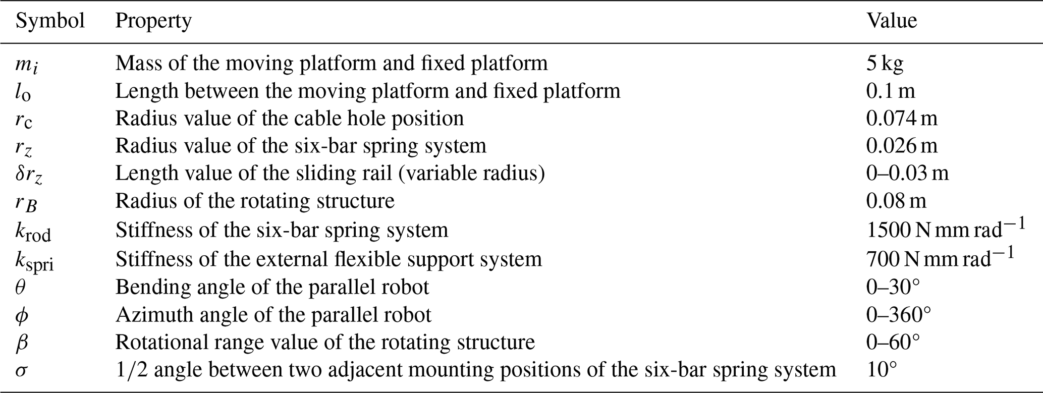
To validate the posture control and dynamic characteristics of the cable-driven, variable-stiffness, compliant parallel robot, kinematic and dynamic simulations are conducted. As shown in Table 1, the basic parameters required for the simulation are provided, including the radius of each mounting hole and the corresponding angle values. Figure 6 visually presents the robot's form in different spatial poses, and the corresponding driving cable lengths are calculated to verify the accuracy and reliability of the established kinematic model.
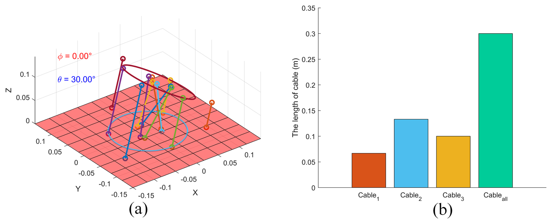
According to the G function defined in Eq. (12), the length of the driving cables in the parallel robot can be calculated from the configuration space qi, which determines the specific posture of the parallel robot shown in Fig. 6. Based on the normal human neck flexion range, and considering the reduction of neck movement by about 30 % when wearing heavy wearable protective equipment, the maximum flexion angle for the parallel robot is set to 30°, closely mimicking the true motion characteristics of the human neck (Zhang et al., 2023).
Using the kinematic equations of the parallel robot and the range of flexion and azimuth angles, the robot's task workspace can be further analyzed. This analysis helps define the reachable range of the robot's end effector, ensuring that the design of the cable-driven, stiffness-variable, compliant parallel robot effectively simulates human neck movement. During the task space analysis, as shown in Fig. 6, the robot's motion shape in 3D space is displayed in lines, and simulation results verify the robot's spatial performance during actual task execution, ensuring that the design meets the expected goals.
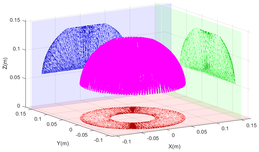
Figure 7 illustrates the workspace of the parallel robot. When the actuation space Δl is in the initial state, the end effector Pq is positioned at the highest point during the robot's motion. By analyzing the movement of the platform, the motion state of the driving cables can be observed. From a top-down view, the robot's movement range in the XY plane is clearly visible, and the driving cable's motion trajectory always stays within the platform's motion range. The workspace analysis provides data support for evaluating neck flexibility and the range of motion.
Through kinematic simulations of the parallel robot, its motion posture is determined, providing the foundation for further analysis of its static and dynamic characteristics. For each posture, the tension (d=1, 2, 3) in the driving cables and the variation in cable length relative to the initial state (i.e., the change in actuation space Δl) are calculated. In the robot's initial state, pre-tensioning the driving cables not only stabilizes its posture but also ensures that the initial length between the platforms remains lo. By analyzing the variations in actuation space Δl and the corresponding cable tensions, the robot can achieve motion control through force-position control, effectively simulating the natural motion of the human neck.
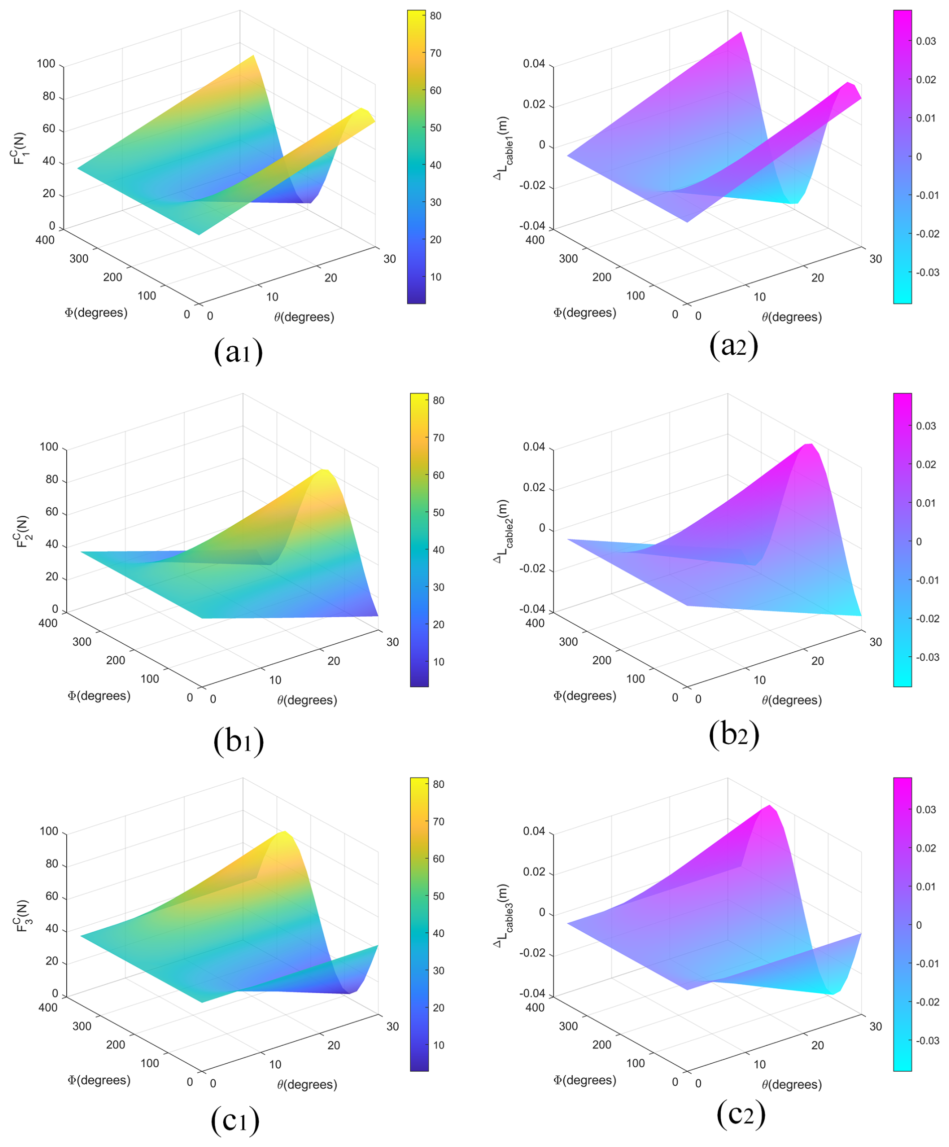
As shown in Fig. 8, by analyzing the range of values for the bending angle θi and azimuth angle ϕi, along with the dynamic equations and the G function, the force variation surface of the driving cables and the actuation space Δl variation surface are derived. The results show that the cable tension surface and the actuation space Δl variation curve exhibit similar trigonometric characteristics. On the left and right sides of Fig. 8, the tension of the same driving cable and the change in actuation space Δl are shown. Comparative analysis indicates that this relationship helps to better understand the parallel robot's dynamic behavior and improves the precision of motion trajectory control. As the actuation space variation of cable u increases, its tension also increases. Additionally, as the bending angle θi of the parallel robot increases, both the cable tension and the actuation space variation gradually increase, though the overall trend still follows a trigonometric curve. When the external flexible support system reaches the limit of its extension and contraction deformation, the tension in the flexible cable reaches its minimum and maximum values.
The parallel robot is connected through a six-bar spring system between the moving platform and the fixed platform, along with an external flexible support system, forming a rigid–flexible coupling structure. This effectively simulates the motion characteristics of the human neck. In the system, the moving platform is rigidly connected to the six-bar spring system and the flexible support system. At the boundary where the moving platform and flexible support system are coupled, force balance is achieved, and the end displacements of both the rigid and flexible bodies remain continuous. Based on this, the dynamic equations of the rigid and flexible bodies are coupled, leading to the establishment of the parallel robot's rigid–flexible coupling equation.
By substituting Eqs. (23) and (24) into Eq. (31), the angular acceleration and linear acceleration during the robot's motion can be calculated. During this process, the torque QD applied by the driving cables on the moving platform balances with the torque generated by the deformation of the flexible support system. Based on Eq. (31), the rigid–flexible coupling equation for the parallel robot is established.
Equation (32) describes the rigid–flexible coupling equation of the parallel robot, where IB is the inertia matrix. The inertia coupling matrix can be calculated from the angular acceleration of the robot during motion. The resistance torque generated by the flexible system forms the torque coupling matrix τin, determined by Eq. (19), which balances with the driving torque QD applied by the driving cables. This leads to the rigid–flexible coupling equation of the parallel robot. The rigid–flexible coupling analysis curve is shown in Fig. 9.
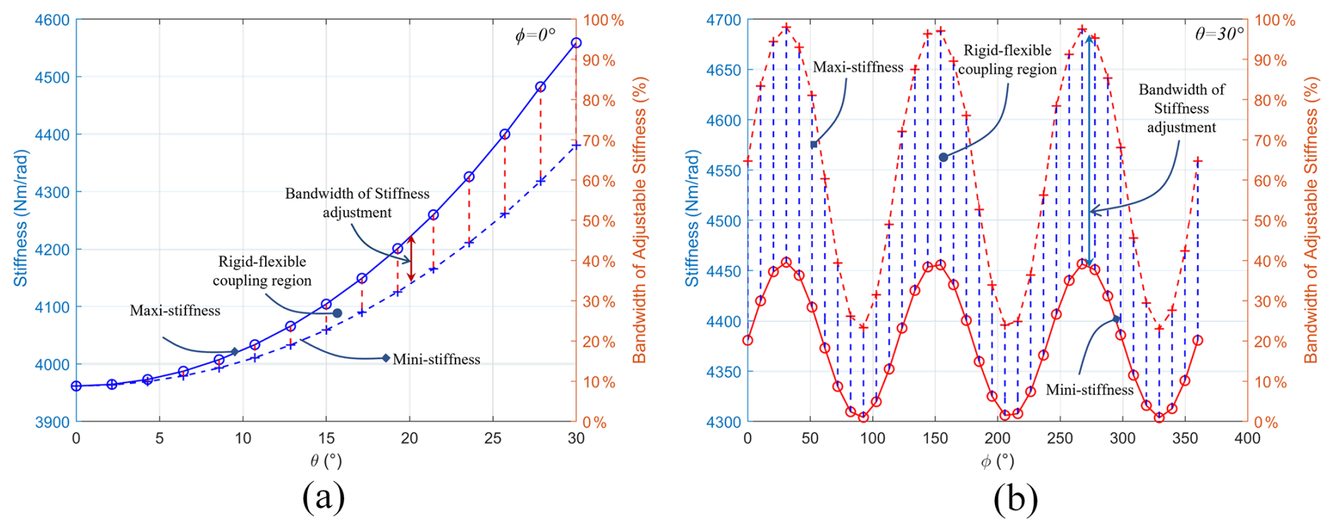
For the parallel robot mimicking the human neck muscles with a variable stiffness system, the stiffness is determined by the stiffness of the driving cables ΔKcable and the stiffness of the flexible system Krobot. By rotating the structure to adjust the motion position of the slide rail, the radius of the external flexible support system can be changed, thereby adjusting the stiffness of the driving cables. When the parallel robot is in a fixed posture, the length of the driving cables cannot change, but adjusting the radius of the flexible support system causes a variation in the resistance torque QR of the flexible system. To maintain the posture of the robot, the driving torque QD of the cables is adjusted accordingly, achieving the function of mimicking the variable stiffness of human neck muscles.
In Eq. (33), the stiffness of the driving cables ΔKcable and the stiffness of the flexible system Krobot are key components of the overall stiffness Kall of the parallel robot. By substituting Eq. (33) into Eq. (34), the stiffness variation rule of the parallel robot can be obtained. To quantitatively evaluate the static and dynamic performance from the numerical results, specific simulation evaluation metrics are defined in Eqs. (30)–(34).
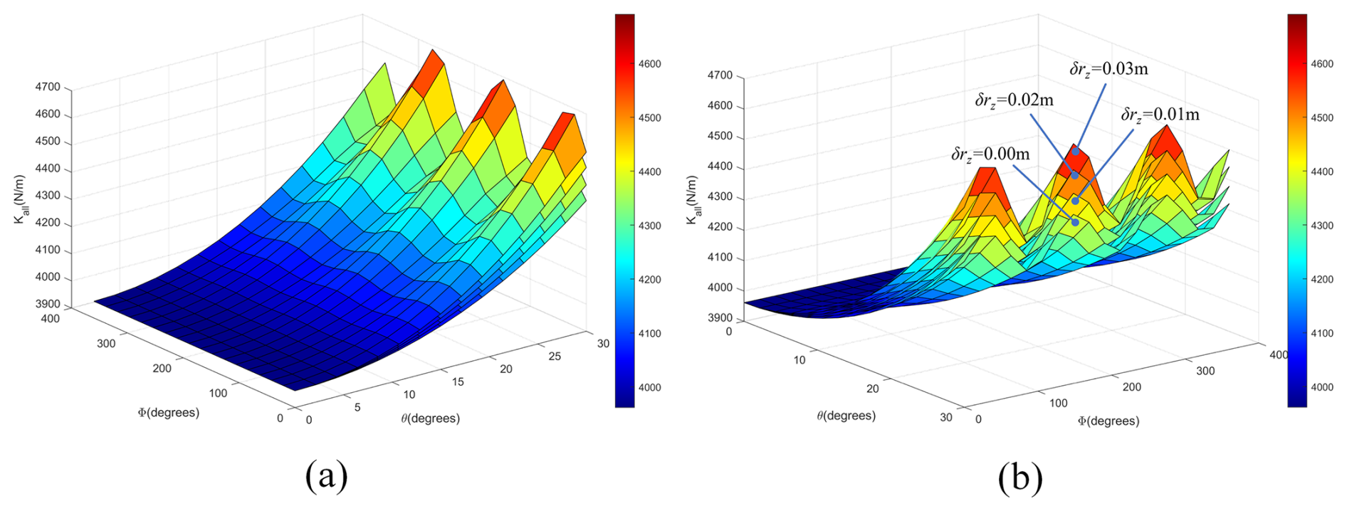
Figure 10 illustrates the variation in the stiffness of the parallel robot. By adjusting the rotational structure to modify the radius of the external flexible support system, the robot's stiffness can be controlled. The figure displays four surface variations corresponding to four different values of the variable radius δrz(β) of the external flexible support system. As the angle β increases, the variable radius δrz(β) also increases, resulting in a corresponding rise in the overall stiffness Kall. The value of Kall reflects the robot's ability to resist external disturbances, analogous to the stabilizing function of human neck muscles when subjected to external forces. The simulation analysis clearly demonstrates the system's ability to adjust stiffness at different postures, further validating its effectiveness and feasibility in mimicking the variable stiffness behavior of human neck muscles. This approach not only provides valuable design insights and a theoretical foundation for the development of biomimetic robots that replicate human muscle functions but also broadens the potential applications of parallel robots in complex and dynamic environments.
Through the aforementioned simulation study, the biomimetic human cervical parallel robot proposed in this paper outperforms the cable-driven parallel robot with a spring-based spine designed by Gao and Song, particularly in simulating the actual range of motion of the human cervical spine (Grazioso et al., 2019). By expanding the range of the bending angle θi, the parallel robot increases its task space, as shown in the blue area of Fig. 11. Additionally, the robot more accurately replicates the characteristics of the cervical bones and muscles in its biomimetic structure. Detailed kinematic and dynamic analyses validate the feasibility of the proposed design and highlight its performance advantages. The kinematic simulation results show that the parallel robot can achieve high motion control precision, effectively adjusting the cervical posture. Furthermore, dynamic analysis demonstrates that the robot's stiffness adjustment mechanism can flexibly alter its overall stiffness, significantly enhancing the structural stability and resistance to external disturbances.

Figure 11Workspace distribution and optimized region of the proposed parallel robot: (a) Y–Z plane view, (b) X–Z plane view showing the optimization area, (c) top view in X–Y plane, and (d) 3D spatial workspace plot.
Nevertheless, from the perspective of human cervical muscle movement mechanisms, the parallel robot still has room for improvement. The current variable stiffness system relies on adjusting the radius of the external flexible support system to achieve stiffness changes. However, this design may cause variations in the robot's size, affecting its biomimetic fidelity and practical application performance. Therefore, future work will focus on optimizing the structural design to better match the shape of the human cervical spine, while maintaining its functional capabilities, in order to enhance both its biomimicry and practicality.
Additionally, the friction effects were neglected in the dynamic calculations of the system in this paper. However, in practical applications, friction can have a non-negligible impact on the robot's motion performance and the accuracy of the end effector. By using lubricants, reducing the contact area along the drive path, and incorporating self-lubricating bushings at the cable fixation points, the negative impact of friction can be effectively reduced, thereby improving the overall performance of the robot.
In summary, the biomimetic human cervical parallel robot still requires further optimization in its structural design to enhance performance, stability, and biomimetic characteristics. Additionally, the frictional effects should be incorporated into the system analysis to account for their potential impact on the robot's motion. Furthermore, differences in motion time during kinematic simulations should be considered, as they may be limited by the computational capacity of the devices used. Future work should focus on optimizing and adjusting the design and simulation strategies to meet the specific needs of various application scenarios.
The robot system designed in this study has demonstrated clear advantages in structural design and stiffness adjustment, but there are still several limitations. Firstly, the current stiffness adjustment relies on the radius change of the external flexible support system, and the response speed and adjustment accuracy need to be further verified through prototype experiments. Secondly, the overall dynamic performance and control strategy of the robot have not been fully developed and improved, and complex working conditions in practical applications place high demands on system stability. In addition, this study focuses on simulating the motion range and stiffness characteristics of the bionic cervical spine and has not addressed the functional adaptability and safety assessment of the system in specific application scenarios such as humanoid robots and rehabilitation. There are still many challenges in the development of practical applications in humanoid robotics and rehabilitation training systems, such as real-time response and robustness of control systems and multi-sensor information fusion.
This paper presents an innovative cable-driven parallel robot with a variable stiffness mechanism, inspired by the motion mechanism of human cervical spine. It improves upon traditional parallel robots by incorporating rigid–flexible coupling and variable stiffness functions, allowing the robot to simulate the collaborative interaction between muscles and bones during neck motion. The robot consists of a motion platform, a fixed platform, drive cables, a six-bar spring system, and an external flexible support system. It is driven by three cables and successfully mimics the motion of the human cervical spine.
The robot adopts an innovative design combining rigid–flexible coupling with a variable stiffness system. This design provides necessary compliance during bending and allows for adjustable stiffness. It effectively simulates the resistance of neck muscles to external disturbances. This novel design offers a new approach for the structural concept of biomimetic cervical robots. Based on this, a systematic analysis of the general kinematics of the parallel robot was conducted. The G and A functions between the configuration space qi and the actuation space Δl are established. The kinematic equations are optimized, leading to a significant improvement in the efficiency of kinematic calculations. In-depth static and dynamic analyses are performed. Using force-position control methods, the precise pose of the robot in space is determined. This greatly enhances the motion accuracy and trajectory stability of the end effector. The rigid–flexible coupling structure and variable stiffness system are also thoroughly studied. Adjusting the radius of the external flexible support system effectively controls the robot's stiffness. This improves its ability to resist external disturbances. These findings provide theoretical support for the rigid–flexible coupling and variable stiffness system. Finally, simulations confirm the effectiveness of the variable stiffness system within its adjustable range. This innovative design opens new research directions for developing biomimetic cervical parallel robots.
Despite these promising results, certain limitations of the present study should be acknowledged. First, the current model omits non-linear cable friction and structural hysteresis, while simplified assumptions were made regarding the mass of specific components. Second, the coupling relationship between bones and muscles has not yet been fully optimized based on detailed cervical spine anatomy. To address these limitations, future research will focus on the systematic optimization of the robotic architecture. Specifically, the dynamic mass and volume distributions of the human head will be fully integrated into the end-effector load profile. Furthermore, the bone–muscle coupling mechanism will be refined using precise anatomical data of the cervical spine to emulate human neck kinematics with higher fidelity. Additionally, practical environmental non-linearities, such as friction, will be incorporated into the governing equations, and force/pose sensors will be integrated into the end effector to establish a closed-loop feedback control scheme, thereby enhancing the operational accuracy and adaptability of the platform in physical applications. Overall, this work provides a novel structural paradigm for biomimetic human cervical parallel robots and offers fresh insights into biological muscle–bone interaction, which is expected to broaden the potential application scenarios in the field of advanced biomimetic robotics.
All the data used in this paper can be obtained by request from the corresponding author.
Da Song and Haochen Wang conceived and designed the study. Da Song, Xinlei Xiao, and Haochen Wang wrote the article. Xinlei Xiao and Yutong Wu assisted in the analysis of simulation results. All authors read and approved the final article.
The contact author has declared that none of the authors has any competing interests.
Publisher's note: Copernicus Publications remains neutral with regard to jurisdictional claims made in the text, published maps, institutional affiliations, or any other geographical representation in this paper. The authors bear the ultimate responsibility for providing appropriate place names. Views expressed in the text are those of the authors and do not necessarily reflect the views of the publisher.
The authors thank the editors and reviewers for their efforts.
This research has been supported by the science and technology innovation and entrepreneurship training program for college students of Jilin Agricultural Science and Technology University (grant no. 202411439012).
This paper was edited by Pengyuan Zhao and reviewed by two anonymous referees.
Bhalkikar, A., Lokesh, S., and Ashwin, K. P.: Kinematic models for cable-driven continuum robots with multiple segments and varying cable offsets, Mech. Mach. Theory, 200, 105701, https://doi.org/10.1016/j.mechmachtheory.2024.105701, 2024.
Camarillo, D. B., Milne, C. F., Carlson, C. R., Zinn, M. R., and Salisbury, J. K.: Mechanics modeling of tendon-driven continuum manipulators, IEEE Trans. Robot., 24, 1262–1273, https://doi.org/10.1109/TRO.2008.2002311, 2008.
Cao, Q., Li, L., Li, J., Li, R., and Wang, X.: A methodology to quantify human-robot interaction forces: a case study of a 4-DOFs upper extremity rehabilitation robot, Robotica, 43, 1469–1490, https://doi.org/10.1017/S0263574725000335, 2025.
Ding, L., Niu, L., Su, Y., Yang, H., Liu, G., Gao, H., and Deng, Z.: Dynamic finite element modeling and simulation of soft robots, Chin. J. Mech. Eng., 35, 24, https://doi.org/10.1186/s10033-022-00701-8, 2022.
Falkenhahn, V., Mahl, T., Hildebrandt, A., Neumann, R., and Sawodny, O.: Dynamic modeling of bellows-actuated continuum robots using the euler–lagrange formalism, IEEE Trans. Robot., 31, 1483–1496, https://doi.org/10.1109/TRO.2015.2496826, 2015.
Falkenhahn, V., Hildebrandt, A., Neumann, R., and Sawodny, O.: Dynamic control of the bionic handling assistant, IEEE/ASME Trans. Mechatronics, 22, 6–17, https://doi.org/10.1109/TMECH.2016.2605820, 2017.
Giannaccini, M. E., Xiang, C., Atyabi, A., Theodoridis, T., Nefti-Meziani, S., and Davis, S.: Novel design of a soft lightweight pneumatic continuum robot arm with decoupled variable stiffness and positioning, Soft Rob., 5, 54–70, https://doi.org/10.1089/soro.2016.0066, 2018.
Godage, I. S., Wirz, R., Walker, I. D., and Webster, R. J.: Accurate and efficient dynamics for variable-length continuum arms: a center of gravity approach, Soft Rob., 2, 96–106, https://doi.org/10.1089/soro.2015.0006, 2015.
Grazioso, S., Di Gironimo, G., and Siciliano, B.: A geometrically exact model for soft continuum robots: the finite element deformation space formulation, Soft Rob., 6, 790–811, https://doi.org/10.1089/soro.2018.0047, 2019.
Jones, B. A. and Walker, I. D.: Kinematics for multisection continuum robots, IEEE Trans. Robot., 22, 43–55, https://doi.org/10.1109/TRO.2005.861458, 2006.
Kang, R., Branson, D. T., Zheng, T., Guglielmino, E., and Caldwell, D. G.: Design, modeling and control of a pneumatically actuated manipulator inspired by biological continuum structures, Bioinspir. Biomim., 8, 036008, https://doi.org/10.1088/1748-3182/8/3/036008, 2013.
Kuo, C., Sheffels, J., Fanton, M., Yu, I. B., Hamalainen, R., and Camarillo, D.: Passive cervical spine ligaments provide stability during head impacts, J. R. Soc. Interface, 16, 20190086, https://doi.org/10.1098/rsif.2019.0086, 2019.
Liu, F., Huang, H., Li, B., Hu, Y., and Jin, H.: Design and analysis of a cable-driven rigid–flexible coupling parallel mechanism with variable stiffness, Mech. Mach. Theory, 153, 104030, https://doi.org/10.1016/j.mechmachtheory.2020.104030, 2020.
Liu, J., Zhao, P., Chen, K., Zhang, X., and Zhang, X.: 1U-sized deployable space manipulator for future on-orbit servicing, assembly, and manufacturing, Space Sci. Technol., 2022, 9894604, https://doi.org/10.34133/2022/9894604, 2022.
Liu, Y., Shi, W., Chen, P., Cheng, L., Ding, Q., and Deng, Z.: Variable curvature modeling method of soft continuum robots with constraints, Chin. J. Mech. Eng., 36, 148, https://doi.org/10.1186/s10033-023-00967-6, 2023.
Luo, R., Yuan, J., Hu, Z., Du, L., Bao, S., and Zhou, M.: Lie-theory-based dynamic model identification of serial robots considering nonlinear friction and optimal excitation trajectory, Robotica, 42, 3552–3569, https://doi.org/10.1017/S0263574724001541, 2024.
Ma, Y., He, Y., Xu, M., Zhou, Q., and Chen, X.: Invariant relative orbits for spacecraft formation flying in high-order gravitational field, Acta Astronaut., 189, 398–428, https://doi.org/10.1016/j.actaastro.2021.08.027, 2021.
Renda, F., Cianchetti, M., Giorelli, M., Arienti, A., and Laschi, C.: A 3D steady-state model of a tendon-driven continuum soft manipulator inspired by the octopus arm, Bioinspir. Biomim., 7, 025006, https://doi.org/10.1088/1748-3182/7/2/025006, 2012.
Renda, F., Boyer, F., Dias, J., and Seneviratne, L.: Discrete cosserat approach for multisection soft manipulator dynamics, IEEE Trans. Robot., 34, 1518–1533, https://doi.org/10.1109/TRO.2018.2868815, 2018.
Sadati, S. M. H., Naghibi, S. E., Shiva, A., Michael, B., Renson, L., Howard, M., Rucker, C. D., Althoefer, K., Nanayakkara, T., Zschaler, S., Bergeles, C., Hauser, H., and Walker, I. D.: TMTDyn: a matlab package for modeling and control of hybrid rigid–continuum robots based on discretized lumped systems and reduced-order models, Int. J. Rob. Res., 40, 296–347, https://doi.org/10.1177/0278364919881685, 2021.
Shao, T.: Fruit harvesting continuum manipulator inspired by elephant trunk, Int. J. Agric. Biol. Eng., 8, 57, https://doi.org/10.3965/j.ijabe.20150801.008, 2015.
Song, D., Xiao, X., Li, G., Zhang, L., Xue, F., and Li, L.: Modeling and control strategy of a haptic interactive robot based on a cable-driven parallel mechanism, Mech. Sci., 14, 19–32, https://doi.org/10.5194/ms-14-19-2023, 2023.
Song, D., Lu, M., Zhao, L., Sun, Z., Wang, H., and Zhang, L.: A novel real-time tension distribution method for cable-driven parallel robots, Robotica, 42, 3692–3708, https://doi.org/10.1017/S0263574724001590, 2024.
Song, D., Lu, M., Zhao, L., Sun, Z., Wang, H., and Zhang, L.: A novel design method for a reconfigurable two-drive cable-driven parallel robot, Proc. Inst. Mech. Eng. C: J. Mech. Eng. Sci., 239, 2049–2062, https://doi.org/10.1177/09544062241293253, 2025.
Thorapalli Muralidharan, S., Gomez, R., and Andrikopoulos, G.: On vibration suppression of a tendon-driven soft robotic neck for the social robot HARU, Front. Rob. AI, 12, 1698343, https://doi.org/10.3389/frobt.2025.1698343, 2026.
Trivedi, D., Lotfi, A., and Rahn, C. D.: Geometrically exact models for soft robotic manipulators, IEEE Trans. Robot., 24, 773–780, https://doi.org/10.1109/TRO.2008.924923, 2008.
Wang, J., Zhao, Y., Zhang, X., Li, Z., and Yao, W.: Model-free intelligent control for space soft robotic manipulators, Space Sci. Technol., 4, 0120, https://doi.org/10.34133/space.0120, 2024.
Yang, C., Geng, S., Walker, I., Branson, D. T., Liu, J., Dai, J. S., and Kang, R.: Geometric constraint-based modeling and analysis of a novel continuum robot with shape memory alloy initiated variable stiffness, Int. J. Rob. Res., 39, 1620–1634, https://doi.org/10.1177/0278364920913929, 2020.
Yang, J., Peng, H., Zhou, W., Zhang, J., and Wu, Z.: A modular approach for dynamic modeling of multisegment continuum robots, Mech. Mach. Theory, 165, 104429, https://doi.org/10.1016/j.mechmachtheory.2021.104429, 2021.
Yang, J., Harsono, E., and Yu, H.: Dynamic modeling and validation of a hybrid-driven continuum robot with antagonistic mechanisms, Mech. Mach. Theory, 197, 105635, https://doi.org/10.1016/j.mechmachtheory.2024.105635, 2024.
Yin, X., Sun, X., Chen, Z., Zhang, X., Li, R., and Yao, Y.: A multi-segment serial–parallel spatial closed-chain capture mechanism based on bionic principles, Mech. Sci., 17, 439–451, https://doi.org/10.5194/ms-17-439-2026, 2026.
Zhang, J., Li, Y., Kan, Z., Yuan, Q., Rajabi, H., Wu, Z., Peng, H., and Wu, J.: A preprogrammable continuum robot inspired by elephant trunk for dexterous manipulation, Soft Rob., 10, 636–646, https://doi.org/10.1089/soro.2022.0048, 2023.
- Abstract
- Introduction
- Configuration design and kinematic analysis of the parallel robot
- Dynamic analysis of the parallel robot
- Simulation analysis of the parallel robot
- Discussion
- Conclusions
- Data availability
- Author contributions
- Competing interests
- Disclaimer
- Acknowledgements
- Financial support
- Review statement
- References