the Creative Commons Attribution 4.0 License.
the Creative Commons Attribution 4.0 License.
 | 09 Oct 2026
Thermal performance regulation of micro-textured interfaces via multi-scale topology optimization and numerical simulation
Xuehua Chen
Jiafu Ruan

The critical challenge of excessive junction temperature caused by ultra-high heat flux densities (> 100 W cm−2) in deep-sea LED fish-attracting lamp (FAL) arrays is addressed. This study proposes a hybrid thermal management scheme integrating interfacial micro-texturing, chimney effect convection, and heat pipe phase change heat transfer, achieving the unification of passive high-efficiency heat dissipation and pressure-resistant sealing. The FAL housing structure is reconfigured using topology optimization to construct chimney effect enhanced flow channels integrated with heat pipe bundle arrays, thereby establishing efficient heat conduction pathways from the phenolic resin substrate (PRS) to the structural periphery. Micro-element texture (MET) arrays are fabricated at the PRS thermal interface to enhance interfacial thermal conductance. Based on multi-physics coupled numerical simulation, a parametric mapping model correlating geometric topology with thermal performance is established through response interface methodology, enabling the parametric optimization of micro-texture configurations. A thermal interface performance-testing platform is constructed to validate the accuracy and reliability of the numerical model. Experimental results demonstrate that the integrated heat pipe technology effectively suppresses LED junction temperature rise; moreover, groove-type MET arrays oriented perpendicular to the gravity direction not only significantly increase the effective heat dissipation area but also optimize the dynamic characteristics of natural convection. This proposed solution reduces the maximum operating temperature of deep-sea FALs by 6.73 % compared with conventional structures, providing an effective engineering solution for thermal structural design of high-power illumination systems.
- Article
(9951 KB) - Full-text XML
- BibTeX
- EndNote


As the core equipment of light-attracting fishing vessels, deep-sea fish aggregating fish-attracting lamps (FALs) exploit the phototactic behaviour of marine species to achieve fish schooling, representing a critical technical approach for enhancing fishing efficiency (Nguyen et al., 2021, 2022; Li, et al., 2025). Currently, most fishing vessels still employ technically mature metal halide FALs as the light source. However, their kilowatt-scale power consumption and relatively low luminous efficacy result in substantial fuel costs that constrain the further improvement of economic benefits in deep-sea fisheries (Peng and Liu, 2021; Ho et al., 2021; Wang et al., 2022). The advent of fourth-generation LED light sources has opened a new chapter in fish-aggregating FAL technology: inherent advantages including extended service life, reduced power consumption, rapid response time, broad attraction range, excellent directional light emission, and superior underwater penetration capability collectively enable multiple benefits, maximized catch yield, decreased fuel consumption, and avoidance of ultraviolet damage, thereby significantly improving economic performance (Xiong et al., 2023; Li et al., 2024; Zhang et al., 2025).
Nevertheless, with the continuous advancement of LED technology, deep-sea fish-aggregating FALs are evolving toward higher power and brightness, imposing more stringent demands on thermal management system performance. During operation, high-power LED chips convert 70 %–80 % of input electrical energy into heat. If this thermal energy cannot be dissipated promptly and effectively, elevated junction temperatures will occur, consequently triggering a cascade of issues including luminous efficiency degradation, accelerated material ageing, and shortened operational lifespan (Malika et al., 2019; Gatapova et al., 2021; Zhou et al., 2021). Therefore, the design of efficient heat dissipation configurations is essential to ensure performance optimization and long-term reliable operation of high-power LED fish-aggregating FALs.
Regarding natural-convection cooling mechanisms, researchers have employed infrared thermography to conduct thermal characterization and comparative analysis of five distinct structural configurations of FALs (Li et al., 2022; Duan et al., 2023). The findings indicate that linear luminaires with non-chip-on-board (non-COB) packaging leverage their structural advantages to achieve effective thermal management through relatively simple passive cooling strategies. Conversely, COB-packaged luminaires necessitate high-performance active cooling systems to provide efficient heat dissipation pathways due to the concentrated heat flux densities generated during operation. In the domain of forced air cooling, investigators have developed integrated LED FAL configurations combining fan-assisted cooling with passive heat dissipation (Ozguc et al., 2023, 2021; Kose et al., 2022). The experimental apparatus utilized three continuous array arrangements with varying irradiation angles, aiming to optimize the installation spacing between fans and heat dissipation systems; however, the improvements in thermal performance remained limited.
Concerning liquid-cooling technology exploration, prior studies have validated the application potential of multi-jet single-phase microchannel liquid-cooling systems for thermal management of high-power LED lighting (Le et al., 2022; Zhang et al., 2024; Velardo et al., 2019). Distinguishing from the aforementioned conventional approaches, existing thermal solutions for deep-sea lighting systems either sacrifice sealing integrity for heat dissipation or rely on active cooling that compromises reliability under high hydrostatic pressure. This study proposes a hybrid thermal management scheme for deep-sea fish-attracting lamps (FALs) combining interfacial micro-texturing, chimney effect convection, and heat pipe phase change heat transfer to unify passive heat dissipation with pressure-resistant sealing. Topology-optimized housing integrates chimney effect channels and heat pipe bundles for efficient heat conduction from the phenolic resin substrate (PRS) to the periphery, while micro-element texture (MET) arrays at the PRS interface enhance thermal conductance. Multi-physics coupled with simulation and response surface methodology enable parametric optimization of micro-textures, validated experimentally. Heat pipes suppress LED junction temperature rise, and gravity-perpendicular groove-type MET arrays enhance heat dissipation area and natural convection. These research outcomes offer viable solutions and engineering references for addressing thermal management bottlenecks in deep-sea high-power LED FAL systems.
2.1 Topology optimization modelling for heat dissipation configurations
In this study, thermal compliance is adopted as the objective function for the steady-state heat transfer problem to characterize the global nature of the optimization target. The minimization of this objective parameter aims to reduce the interface temperature of multi-scale configurations and to enhance heat dissipation efficiency. The concept of thermal compliance is analogous to thermal potential energy. Minimizing thermal compliance enables maximized heat transfer to the surrounding medium, thereby achieving the optimal temperature distribution across the micro-textured interface (Yan et al., 2023; Bülbül et al., 2025; Yang et al., 2023). Accordingly, the topology optimization of the heat dissipation interface configuration can be formulated as follows:
where θ is the element density of the heat dissipation interface; C is the thermal dissipation deficiency, with units of (J K); T is the temperature vector of the heat dissipation configuration interface nodes; K is the thermal conductivity matrix of the heat dissipation configuration interface; P is the thermal load vector of the heat dissipation configuration interface; Te is the temperature vector of the configuration element interface nodes; θe is the relative density of each material element; ve is the interface element volume; V0 is the total volume of the heat dissipation interface configuration design domain; f is the material volume fraction; n is the total number of interface elements; θmin is the minimum interface element density to prevent singular matrices during computation, typically set to 1.0 × 10⁻³; K0 denotes the interfacial element thermal conductivity matrix at unit relative density (ρ=1.0) within the heat dissipation topology design domain; and fe(θe) is an artificially defined exponential function model, which can be expressed as .
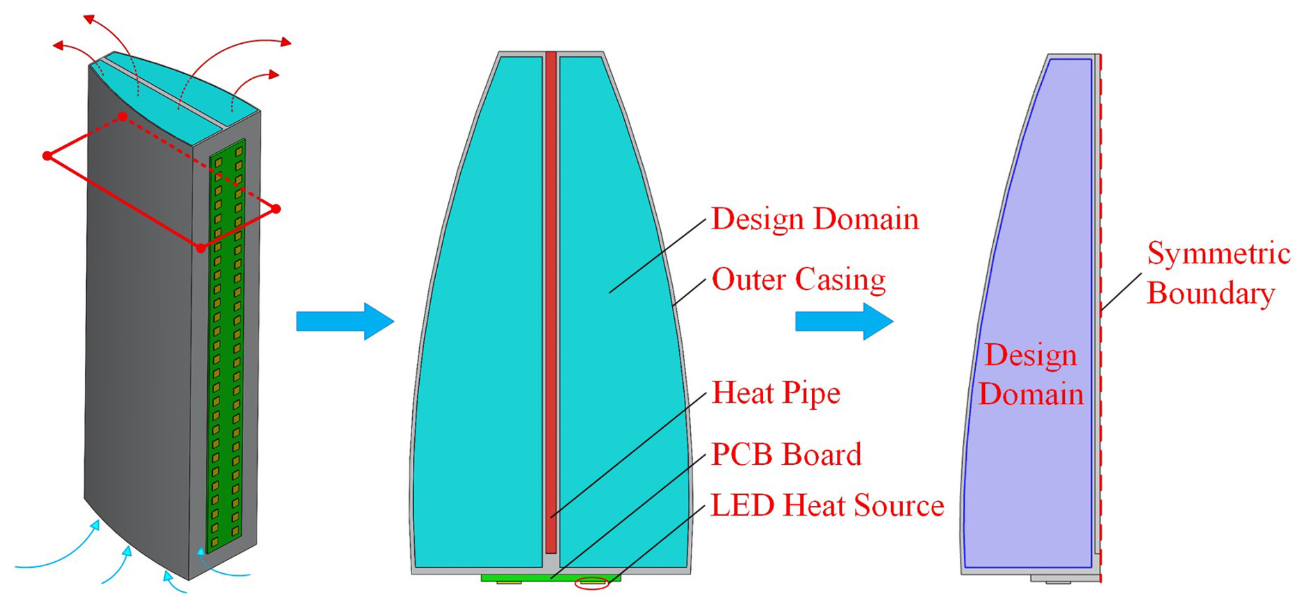
Figure 1Model construction for topology optimization of heat dissipation configurations using equivalent simplification strategies.
Figure 1 presents the chimney structure heat sink model, in which the blue region denotes the design domain for topology optimization, while all other regions constitute the non-design domain and remain unchanged throughout the optimization process. In this study, the heat sink is designed using the classical two-dimensional cross-sectional SIMP topology optimization method coupled with axial stretching rather than more advanced alternatives such as the level set method, the moving morphable component (MMC) method, or multi-objective collaborative optimization. This methodological choice is justified by both engineering practicality and numerical considerations, as elaborated upon below.
- 1.
The targeted LED fish-attracting lamp heat sink is intended for industrial mass production, for which aluminium profile extrusion, the dominant process for fabricating components with uniform cross-sections, represents the mainstream manufacturing route. Since structures with axially invariant cross-sections are inherently compatible with the extrusion process, two-dimensional planar optimization is better suited to large-scale industrial fabrication.
- 2.
The SIMP method offers clear physical interpretability, low computational cost, and robust iterative convergence, thereby facilitating rapid preliminary optimization of passive heat dissipation structures and efficient exploration of high-performance thermal layouts. Admittedly, single-objective SIMP optimization tends to generate excessively slender, branching structures with limited mechanical robustness, which are susceptible to vibration-induced deformation and thermal stress concentration under realistic service conditions. To mitigate these deficiencies, a regularization strategy is incorporated into the optimization process: an appropriate filter radius is imposed during the iterations to suppress overly thin and fragile structural branches, yielding a nearly uniform wall thickness and a well-regulated structural layout. This strategy strikes a balance between natural-convection performance and structural service reliability without incurring additional computational overhead.
- 3.
The temperature gradient induced by the chimney effect and the associated flow field variation remain essentially uniform along the gravitational direction, and the cross-sectional heat flux pattern perpendicular to the stretching axis exhibits no substantial alteration. Moreover, the heat conduction path within each cross-section is consistently governed by the intrinsic thermal properties of the material. Consequently, the two-dimensional topology optimization results obtained from representative cross-sections remain physically valid for the stretched three-dimensional structure.
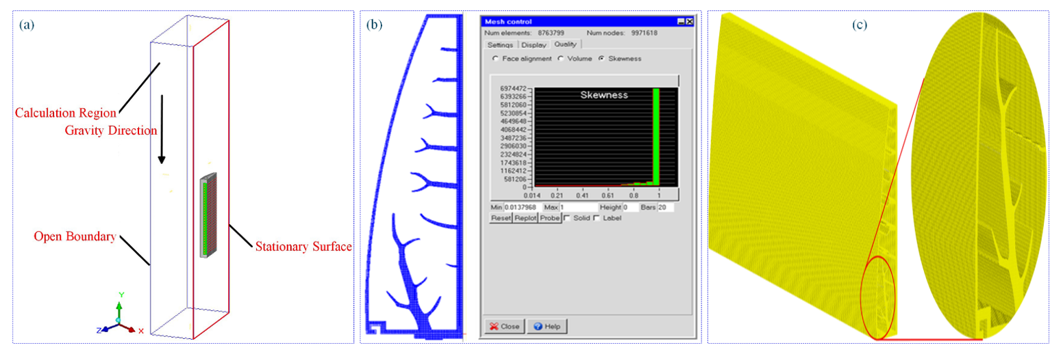
Figure 2The computational domain, mesh generation strategy, and mesh quality of the simulation model. (a) Computational domain of the simulation model. (b) Mesh generation. (c) Mesh quality.
2.2 Thermal dissipation deficiency analysis considering the chimney effect
The thermal design of the deep-sea FAL heat dissipation configuration is based on the chimney effect enhancement principle. By optimizing the natural-convection channels within the heat dissipation structure, the aerodynamic driving efficiency is enhanced, thereby improving the natural-convection heat transfer coefficient in the structural domain of the FALs and achieving a systematic improvement in overall heat dissipation performance (Rahimi et al., 2018; Ammosov et al., 2020; Mu et al., 2022). This configuration converts the buoyancy force generated by density differences arising from temperature gradients between the internal and external regions into the dominant driving force for airflow motion (Ruan et al., 2025; Bai et al., 2024; Eng et al., 2023). The thermodynamic behaviour can be quantitatively described by the following governing equations (Al-Karagoly et al., 2020; Parlak et al., 2021):
where ΔP is the buoyancy pressure difference (Pa); ρc is the density of cold air; and ρh is the density of hot air; ( kg m−3), wherein T is the absolute temperature (K), g is the gravitational acceleration (m s−2), and H is the vertical height of the micro-textured heat dissipation shell (chimney-shaped) in millimetres (mm).
In chimney-driven natural convection, buoyancy-induced flow is characterized by the Rayleigh number (Ra), which determines the resulting flow regime (Firoozeh et al., 2023; Miansari et al., 2023).
In the above, Gr denotes the Grashof number, , with a larger Grashof number indicating stronger buoyancy effects in the fluid. Pr represents the Prandtl number, ; υ is the kinematic viscosity of air, υ≈ 1.8 × 10⁻⁵ m2 s−1; and α is the thermal diffusivity (m2 s−1). For air, Pr≈ 0.7. β denotes the thermal expansion coefficient for an ideal gas, (K−1).
The internal air velocity is determined by the interplay between buoyancy and flow resistance (Yang et al., 2024; Jebali et al., 2026). Under the assumption of steady laminar flow within simplified configurations, the air velocity can be derived as follows (Hu et al., 2024):
For the above, the local resistance coefficients for inlet (Ki) and outlet (Ko) are defined as follows: for a sharp-edged inlet, Ki≈ 0.5; if the inlet is rounded then Ki≈ 0.04 ∼ 0.2. Since the outlet discharges directly to atmosphere, Ki≈ 1.0. λ represents the channel friction coefficient, and dh denotes the chimney structural channel diameter (mm). For irregular geometric cross-sections, the hydraulic diameter can be employed (where A is the cross-sectional area, and C is the wetted perimeter).
2.3 Thermal simulation configuration and boundary conditions
To reduce computational resource requirements, the LED chip and phenolic resin substrate (PRS) are geometrically simplified, and the thermal contact resistance between interfaces is neglected in the heat dissipation analysis. While thermal contact resistance is not explicitly resolved in the numerical model, a thin thermal interface material layer is incorporated between the PRS and the heat-dissipating structure to replicate the actual product assembly. The layer is characterized by an effective thermal conductivity calibrated against supplier-provided experimental data. This modelling strategy effectively consolidates the bulk thermal resistance of the interface material and the contact resistances at the two adjoining boundaries into a single equivalent layer, representing a conventional engineering simplification. Thermal simulations are performed using Ansys 2023 R2 Icepak software. Owing to the geometric complexity, only half of the model is simulated. The symmetry plane is defined as an adiabatic wall with zero heat flux, while all other surfaces are treated as open boundaries to permit natural convection. The temperature boundary condition at the maximum Y coordinate is removed, and the simulation model is illustrated in Fig. 2. Graded element orders are employed for mesh discretization: third-order elements are assigned to the LED module, while second-order elements are adopted for the heat sink, PRS, and heat pipes, with localized refinement applied to boundary layer regions. The mesh partitioning and overall quality are illustrated in Fig. 2b and c, respectively. The minimum mesh skewness is 0.014, with the majority of elements exhibiting values close to 1.
Table 1Micro-element texture configuration design for heat dissipation structures of FALs.
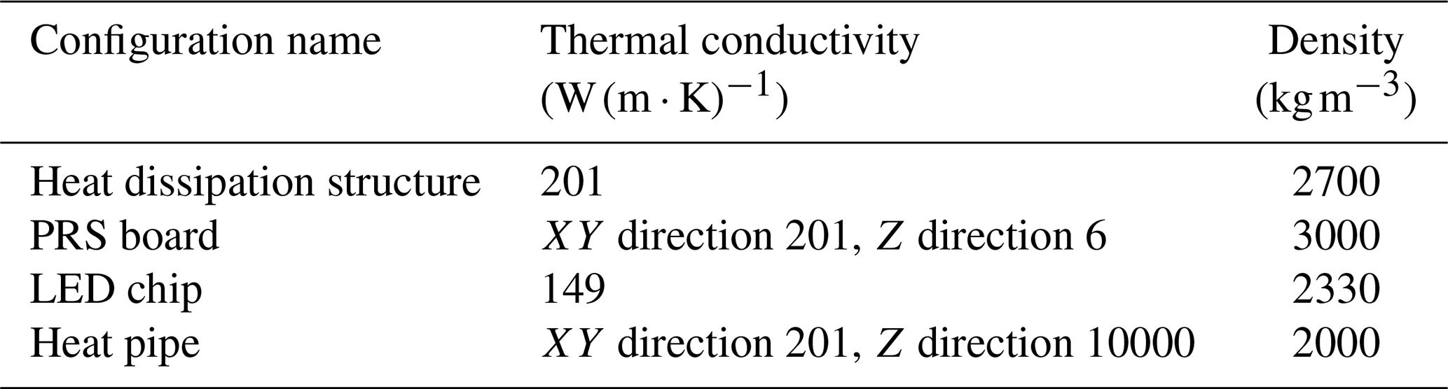
Notably, the skewness criterion for structured hexahedral meshes in Ansys 2023 R2 Icepak software differs from that of conventional CFD solvers, in which a skewness value approaching 1 indicates superior mesh quality. A mesh independence study is conducted to eliminate the influence of grid density on numerical accuracy and to ensure the reliability of the simulation results. When the element count is increased from 6.3 × 10⁶ to 8.8 × 10⁶, the maximum temperature variation of the LED remains below 0.2 %, with negligible differences observed in the temperature field distribution. A further refinement to 10.3 × 10⁶ elements yields no appreciable improvement in numerical accuracy yet substantially increases the computational cost. Consequently, a mesh comprising approximately 8.8 × 10⁶ elements is adopted, achieving an optimal balance between numerical precision and computational efficiency. The materials employed in this study are as follows: 6063 aluminium alloy is used for fabricating the heat dissipation structure, a high-thermal-conductivity metal substrate is adopted for the PRS board, and silicon serves as the material for the LED chip. Heat pipes are incorporated for subsequent thermal simulations, with the relevant material properties detailed in Table 1. Each LED chip is designated as a 7.0 W heat source, corresponding to 70 % of its total thermal power (assuming a typical electro-optical conversion efficiency of 30 %).
The Discrete Ordinates (DO) radiation model, which is suitable for open systems with natural convection, is employed in this study. The Rayleigh number (Ra) is calculated using Eq. (3) as Ra = 2.878 × 10⁸ < 109, indicating that the airflow under natural convection is laminar. The gravitational force acts in the Y direction. Additionally, considering the high ambient temperatures encountered during marine operations of the FAL, the ambient temperature is set to 30°C.
To reduce computational cost, the LED chip and PCB substrate were simplified, and the effect of interfacial contact thermal resistance on heat dissipation was neglected. The heat sink and heat pipe are monolithically integrated, eliminating interfacial thermal resistance within the composite structure. For the LED–PCB and PCB–heat sink interfaces, ideal thermal contact was assumed in the simulations. To justify this simplification, the contact thermal resistances of the solder layer at the LED–PCB interface and the thermal grease layer at the PCB–heat sink interface were quantified. The LED–PCB joint, bonded with tin–lead solder, yields a contact thermal resistance of 0.00408 K W−1, whereas the bolt-fastened PCB–heat sink interface with thermal grease yields 0.00126 K W−1. Their combined value accounts for only 2.35 % of the total system thermal resistance. Furthermore, a dedicated sensitivity analysis was performed to assess the robustness of this simplification: doubling the contact thermal resistance increases the maximum heat sink temperature by only 1.76 %, demonstrating a negligible influence on the overall thermal performance.
Thermal simulations were performed in ANSYS Icepak using a half-model strategy. The right boundary was defined as the geometric symmetry plane and assigned adiabatic, no-slip wall conditions, which satisfy the physical symmetry requirements of zero normal velocity and zero normal heat flux, thereby ensuring mass and energy conservation. Since the chimney-effect-driven natural convection in this study is dominated by flow along the gravity direction, tangential flow at the symmetry plane is minimal, and the no-slip condition has a negligible effect on the overall flow and thermal fields. Comparative validation confirms that the numerical deviation introduced by this simplification is within 1 % relative to ideal symmetry boundary conditions, verifying the rationality of the half-model setup. All remaining boundaries were specified as open boundaries. Since the computational domain is open to the atmosphere and the ambient temperature is fixed, enlarging the domain introduces virtually no additional error: the maximum junction temperature deviation between the original domain and a threefold-larger domain is less than 0.1 %. This small deviation confirms that the flow and thermal fields are fully developed within the original computational domain. Therefore, the present domain configuration and boundary conditions are sufficient to accurately reproduce the actual natural-convection environment.
To verify the robustness of the numerical assumptions and parameter settings, a comprehensive sensitivity analysis was performed on key engineering parameters, including contact thermal resistance, surface emissivity, ambient temperature, LED heat generation ratio, and material thermal conductivity. All evaluations were conducted within practical engineering fluctuation ranges. The PCB–heat sink interface, bonded with high-performance thermal grease and bolted fastening, exhibits negligible variation in contact thermal resistance and thus has no influence on the relative cooling performance of the different heat dissipation schemes. When the heat sink emissivity ranges from 0.7 to 0.9, the resulting temperature deviation remains below 1.5 °C. An ambient temperature fluctuation of ± 2 °C induces only a uniform temperature offset without altering the relative performance differences among the structures. When the LED heat generation ratio varies over the commercial range of 65 %–75 %, the maximum temperature fluctuation remains within 3 °C. Moreover, reasonable variations in material thermal conductivity have negligible effects on the heat dissipation trends of the structures. In conclusion, moderate fluctuations in the key parameters, together with the adopted model simplifications, do not alter the core findings of this work, confirming the rationality of the numerical setup and the robustness and reliability of the simulation results.
2.4 Geometric configuration design of the capillary suction tube
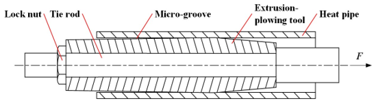
Considering both the machining constraints of the monolithic heat pipe and the operating environment of the fish-attracting light, a grooved heat pipe is selected as the capillary wicking core structure. Leveraging the excellent plastic deformation capability of aluminium alloy 6063, a metal plowing process is adopted to fabricate the microgrooves in the monolithic heat pipe, with the forming principle illustrated in Fig. 3. Prior to the extrusion-plowing operation, the heat sink structure of the FAL is firmly secured in position, while the extrusion-plowing tool is mounted onto the pull rod via a locking nut and precisely aligned with the heat pipe opening. Upon initiation of the extrusion-plowing process, the pull rod advances slowly along the inner wall of the heat pipe under external force, and the extrusion-plowing tool then exerts compressive stress on the inner wall, inducing plastic deformation and lateral material flow.
As the metal continuously bulges outward at both ends, a capillary wick structure with continuous fins is formed within the microgrooves of the heat pipe. A schematic diagram of the extrusion-plowing tool is presented in Fig. 4. As the tube shell of the integrated heat pipe serves as the heat dissipation structure, acetone, compatible with 6063 aluminium alloy, is selected as the working fluid.
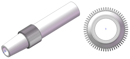
Figure 5 illustrates the sequential procedures for vacuum evacuation, working-fluid charging, and final sealing of the heat pipe. To facilitate these operations during fabrication of the heat dissipation structure, an extension tube was installed at the reserved heat pipe port, and a T joint with two channels was hermetically attached to the protruding end of the extension tube using a sealing material.
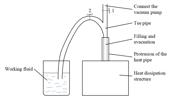
During vacuum evacuation, channel 2 was closed, and the vacuum pump extracted the air from the heat pipe through channel 1. During fluid charging, channel 1 was closed, and the working fluid was drawn into the pipe to the predetermined fill volume by exploiting the pressure differential between the evacuated interior and the ambient atmosphere. In the final sealing step, both channels were closed, and the protruding extension tube was crimped and severed using a high-temperature clamp, thereby establishing a permanent hermetic seal. Acetone was selected as the working fluid for the integrated heat pipe since the tube shell serves as the primary heat dissipation component and acetone exhibits favourable chemical compatibility with 6063 aluminium alloy.
Table 2Micro-element texture configuration design for heat dissipation structures of FALs.
2.5 Multi-scale micro-element configuration design for textured surfaces
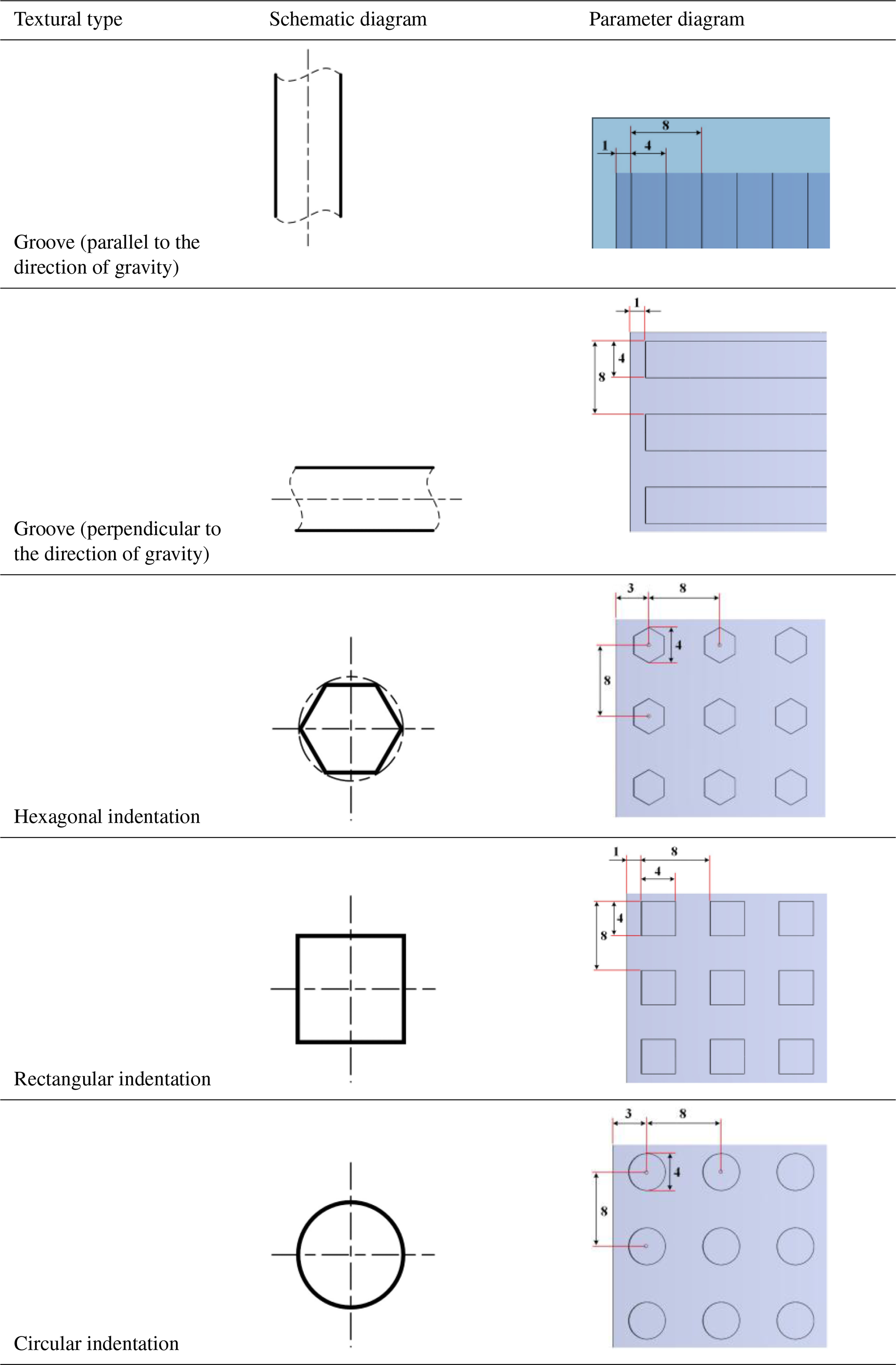
To investigate the thermal dissipation performance of heat sink structures in fish-attracting lights under various surface textures, five distinct surface texture configurations are designed, all featuring a uniform depth of 0.2 mm, as detailed in Table 2.
To validate the simulation results, a heat dissipation test platform for the FAL is developed, as shown in Fig. 6. The experimental setup comprises a test prototype, an 1800 W adjustable DC power supply, a temperature acquisition module, temperature sensors, and other auxiliary components.
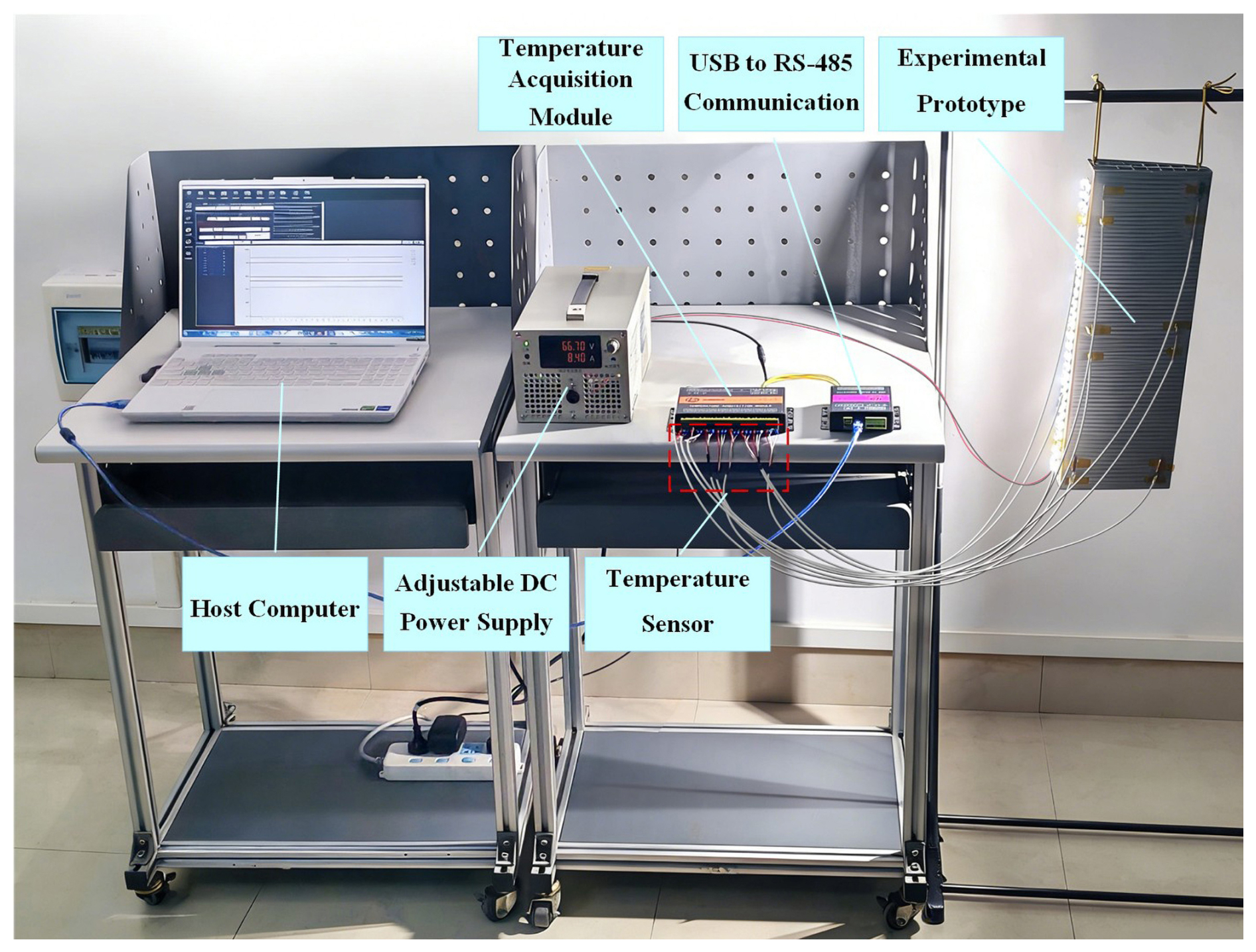
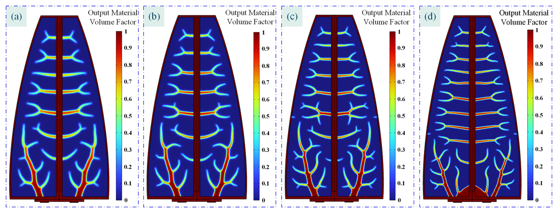
Figure 7Topology optimization of LED substrates for deep-sea FALs under varying filter radii. (a) Rmin = 3.0 MES, (b) Rmin = 2.5 MES, (c) Rmin = 2.0 MES, (d) Rmin = 1.5 MES.
Considering the 0.6 mm thickness of the LED substrate for deep-sea FALs, the maximum mesh element size (MES) is set to 0.6 mm. With the mesh held constant, the influence of varying filter radii (Rmin) on the topology optimization results of the substrate structure is systematically investigated, as shown in Fig. 7.
Figure 7a reveals that an excessively large filter radius leads to over-smoothing of the deep-sea FAL substrate topology, accompanied by the loss of fine-scale features and a consequent degradation in structural service performance. Conversely, an overly small filter radius (as illustrated in Fig. 7c and d) generates jagged boundaries and proliferates numerous microscopic branches. Although these microstructural features are conducive to enhancing interfacial heat transfer efficiency, their dimensions transcend the manufacturability limits of conventional machining, casting, and additive manufacturing processes.
Moreover, they are prone to fracture failure under vibratory or thermal loading. Therefore, an optimal filter radius must be determined through a comprehensive trade-off between topological fidelity and manufacturability. Based on the optimized topology, a three-dimensional solid model of the deep-sea FAL is established, as shown in Fig. 8.
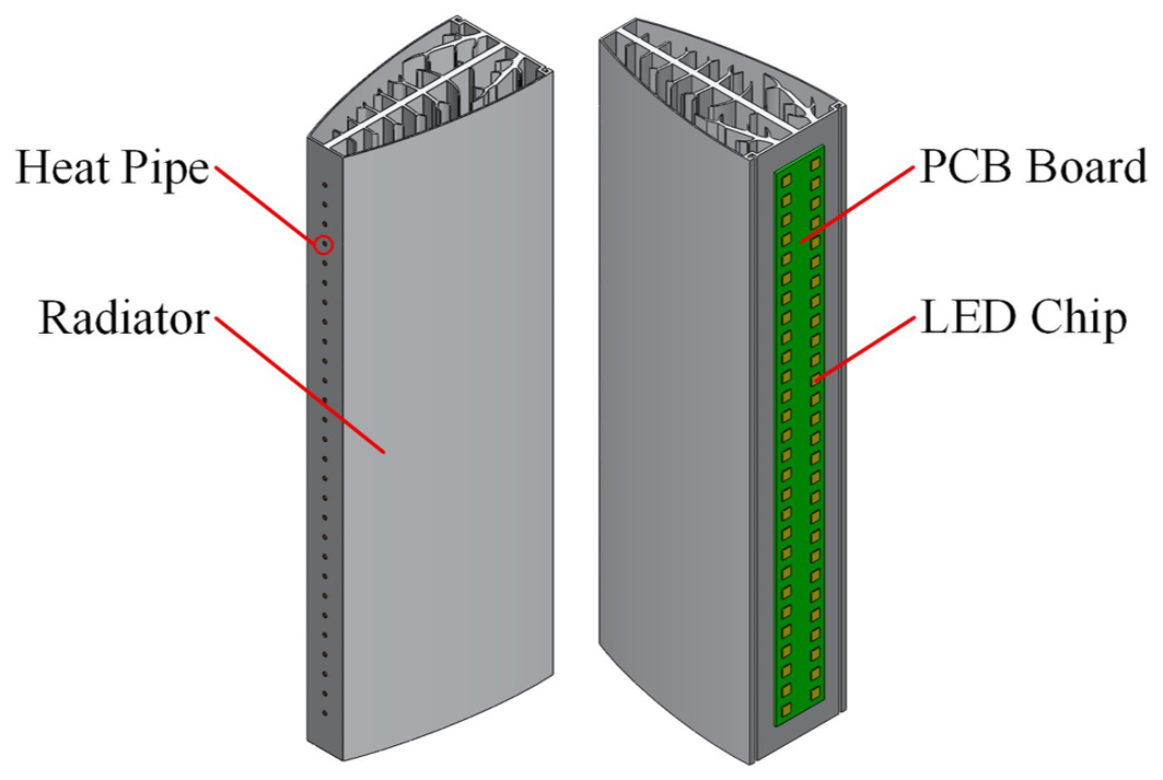
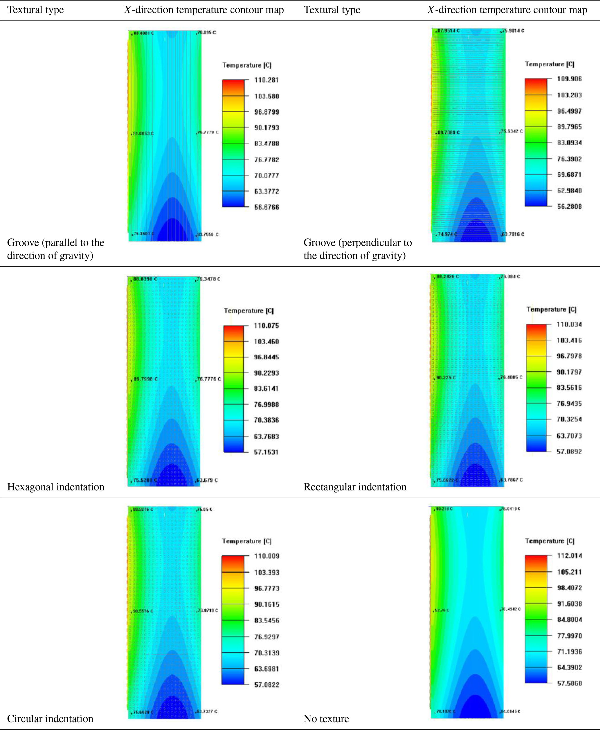
Table 3 presents the comparative simulation results for various surface textures. Among the proposed configurations, grooves oriented perpendicular to the gravity direction yield the most significant improvement in the heat dissipation performance of the FAL system. These grooves function as a series of miniature dams along the upward path of natural-convection airflow, periodically disrupting the thermal boundary layer and enhancing fluid mixing, thereby promoting more effective heat exchange between the near-surface air and the heat dissipation structure. In contrast, grooves aligned parallel to the gravity direction act in concert with the primary flow, guiding air upward along the channels; this behaviour tends to stabilize or even thicken the thermal boundary layer, resulting in degraded heat transfer in certain regions. While dimple-type textures, including circular and rectangular pits, can also disturb the thermal boundary layer to enhance local heat transfer, their effects remain localized and discrete. As airflow passes over these dimples, stable recirculating vortices develop within the cavities, and the poor exchange between the recirculation zone and the mainstream weakens convective heat transfer, rendering the overall thermal performance of the FAL inferior to that achieved with perpendicular grooves, enabling continuous and complete disruption of the boundary layer. Accordingly, this study adopts grooves perpendicular to the gravity direction as the optimal micro-scale surface texture configuration.
Table 3Comparative simulation of temperature contours for different micro-scale surface texture configurations.
This study employs the response surface methodology, with the multi-scale configuration parameters of surface micro-texture, namely, groove width (W), groove spacing (S), and groove depth (D), as independent variables, to establish a response relationship model that correlates these parameters with the maximum temperature of the deep-sea FAL structure. These parameters are further treated as associated functions of the multi-scale configuration parameters of surface micro-texture, thereby elucidating the time-varying characteristics of this temperature extremum. Table 4 lists the experimental factors, along with the corresponding coded levels employed in the response surface design.
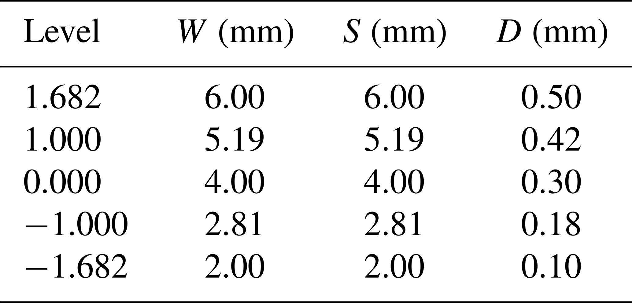
The simulation analysis results obtained using Ansys 2023 R2 Icepak software, together with the corresponding simulation validation test protocols, are summarized in Table 5. Statistical analysis of the simulation validation test data is performed using Design-Expert 13 (v13.x) to evaluate the effects of individual experimental factors on the response variables.
Table 5Correspondence between simulation results and validation test schemes.
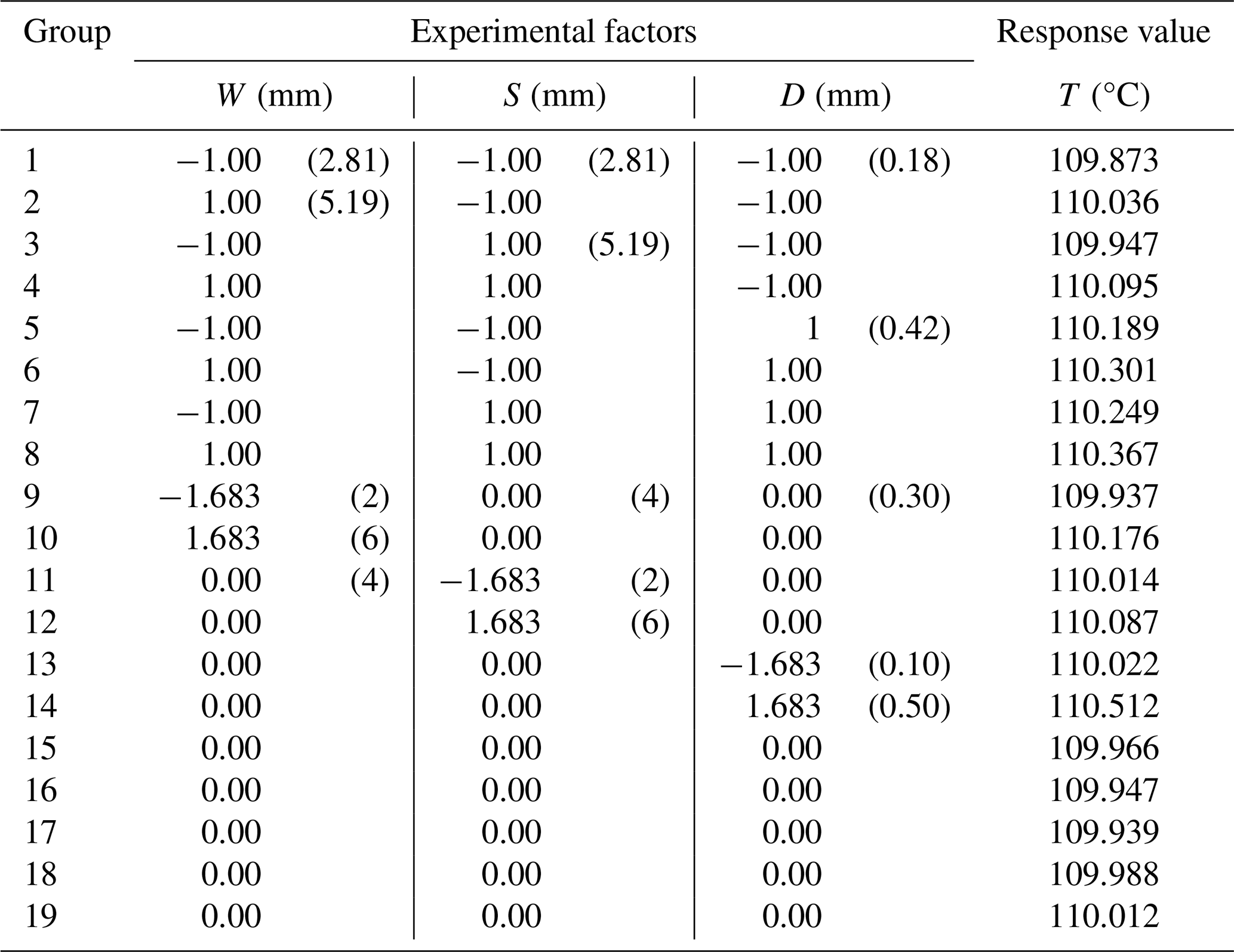
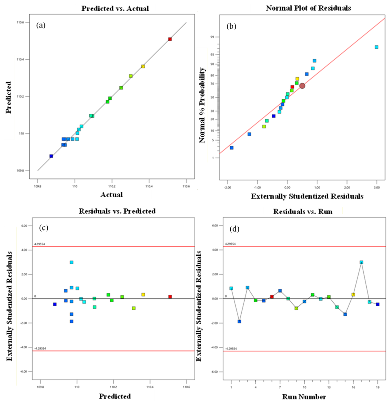
Figure 9Residual diagnostic plots. (a) Predicted versus actual values. (b) Normal probability plot of residuals. (c) Residuals versus predicted values. (d) Residuals versus run order.
Based on the experimental data presented in Table 5, a second-order response surface regression model is developed using response surface methodology, with groove texture parameters as independent variables and interface temperature as the response variable.
A second-order response surface methodology is employed, with groove-type micro-texture parameters serving as input variables, to establish a regression-based prediction model for the maximum interface temperature. The model exhibits excellent agreement with simulation data, and the corresponding temperature evolution is presented in Fig. 9. The predicted and actual values demonstrate strong overall agreement, with only minor deviations and no significant discrepancies. The normal probability plot indicates that the residuals are approximately normally distributed; the residuals-versus-fitted plot shows no discernible pattern, precluding heteroscedasticity, and the residuals-versus-run-order plot reveals no systematic trend, ruling out serial correlation. Collectively, these residual diagnostics confirm that all fundamental assumptions underlying the second-order response surface model are satisfied, establishing its statistical validity.
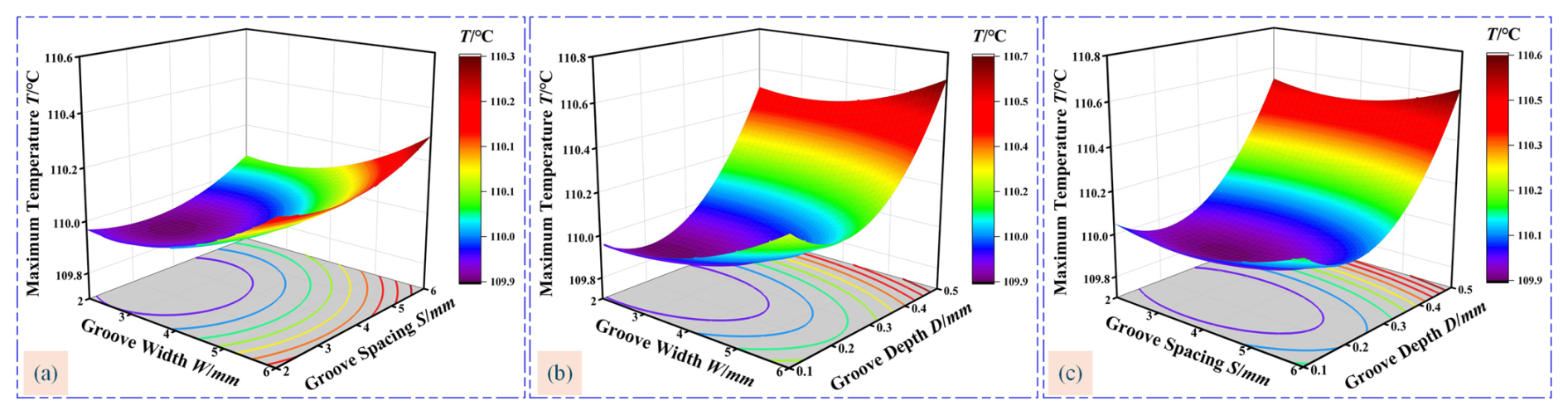
Figure 10Time-varying coupling characteristics between multi-scale parameters of groove-type micro-texture configurations and the maximum temperature response surface of FAL structural interfaces. (a) Variation of W and S. (b) Variation of W and D. (c) Variation of S and D.
To further elucidate the coupled relationship between the multi-scale parameters of grooved micro-texture configurations and the peak interfacial temperature of FAL structures, a time-dependent model is developed using response surface methodology, with the results presented in Fig. 10.
Figure 10a–c illustrate the interactive effects of pairwise micro-texture parameter combinations on the maximum interface temperature. Through quantitative resolution of the coupling intensity among multi-scale parameters, a comprehensive evaluation of the overall heat dissipation performance of the deep-sea FAL is achieved.
The contour density variations indicate that the multi-scale parameters of the groove-type micro-texture configuration affect the maximum interface temperature with the following order of significance: groove depth (D) > groove width (W) > groove spacing (S). Among these, groove depth (D) exerts the most pronounced influence on the thermal performance of the FAL structure, and its underlying mechanisms can be elucidated from the following two aspects: (1) the first is the convective enhancement effect. The groove depth directly governs the disturbance intensity of the thermal boundary layer and the vortex generation capability. As the groove depth increases, the thermal boundary layer undergoes more severe disturbances, thereby inducing stronger vortices and enhancing convective heat transfer. Nevertheless, this convective improvement is not monotonic. Once the groove depth exceeds a critical value, the benefits derived from thermal boundary layer disturbances diminish markedly, while the flow resistance coefficient rises sharply, causing the overall effectiveness of convective enhancement to decline instead. (2) Second is the thermal conduction weakening effect. The attenuation of solid-phase heat transfer paths by groove depth exhibits spatial non-uniformity. The core function of the heat sink is to rapidly conduct the heat generated by the LED chip to the FAL substrate; however, as the groove depth increases, the wall thickness at the groove root progressively decreases, gradually obstructing the heat conduction path from the heat sink toward the region away from the LED chip. An optimal balance must be sought between the convective enhancement benefits brought by increased groove depth and the concomitant weakening of the heat conduction paths so as to maximize the overall thermal performance of the FAL.
Groove width (W) is a secondary factor influencing the maximum interfacial temperature of the FAL structure. When W is too small, the grooves form narrow micro-slits. At the groove entrance, the airflow experiences severe contraction, preventing most of the air from penetrating into the groove interior; only weak turbulent eddies develop along the groove edges, resulting in inefficient convective heat transfer. Conversely, an excessively large W is equivalent to the continuous removal of a segment of the FAL substrate, reducing the effective heat conduction cross-sectional area and significantly impeding thermal conduction.
Groove spacing (S) is the least significant factor affecting the maximum interfacial temperature of the FAL structure. During surface texturing, material removal to form grooves results in a wall thickness at the groove spacing that exceeds that at the groove width (the difference being the groove depth D). Thus, the groove spacing effectively corresponds to the width of the heat dissipation fins. An excessively small spacing increases the fin count but makes each individual fin thinner, degrading heat transfer capability and preventing heat from being effectively transferred from the proximal end adjacent to the LED heat sink to the distal end. Conversely, an excessively large spacing produces an insufficient number of grooves to effectively disrupt the thermal boundary layer.
Based on Eq. (5), a mathematical model is formulated with the maximum interfacial temperature as the optimization objective, aiming at the global optimization of the overall thermal performance of the FAL structure. The objective function is defined in terms of groove parameters, which yields the following expression:
Throughout the parameterized multi-scale design of micro-texture configurations, the determination of groove geometric parameters is restricted by multiple coupled practical engineering limitations, thereby ensuring that the optimized configurations are readily manufacturable in engineering practice.
A genetic algorithm is implemented on the MATLAB platform to perform multi-objective optimization of multi-scale parameters for groove-type micro-textures in the FAL structure. Following iterative refinement, the optimal parameter combination is identified as follows: groove width W = 2.48 mm, spacing S = 3.37 mm, and depth D = 0.22 mm. With this optimal configuration, the peak interfacial temperature of the FAL structure is reduced to 109.868 °C, thereby effectively enhancing the thermal management performance of the deep-sea FAL.
Table 6Comparative analysis of FAL simulation results for different multi-scale micro-texture configurations.
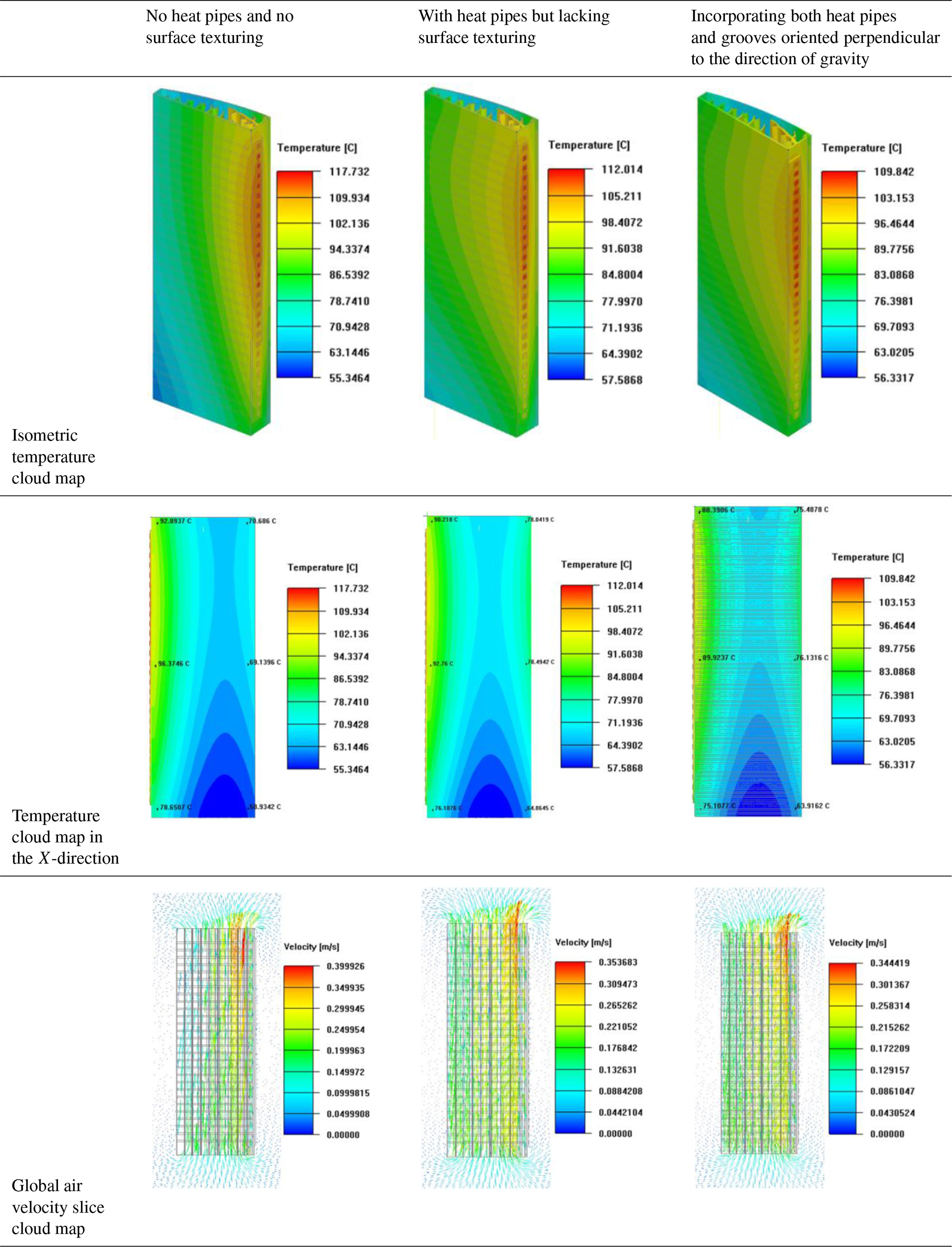
Table 6 presents a comparative analysis of simulation results for three multi-scale micro-textured structural configurations: (1) without heat pipes and without surface textures, (2) with heat pipes but without surface textures, and (3) a synergistic integration of heat pipes with groove micro-textures oriented perpendicular to the gravity direction (based on the aforementioned optimal parameters).
The interface temperature contours presented in Table 6 reveal that integrating heat pipes significantly homogenizes the temperature distribution across the FAL heat dissipation structure. This improved temperature uniformity effectively reduces the thermal gradient between the proximal and distal ends of the heat pipe, thereby mitigating heat accumulation in the PRS region. The optimized interface temperature field enhances overall convective heat transfer performance, effectively lowering the LED junction temperature. With the further incorporation of surface textures, the maximum interface temperature of the FAL exhibits an additional reduction compared to the configuration integrating heat pipes alone (without texturing).
This enhancement is primarily attributed to the extended heat dissipation area and intensified airflow turbulence induced by surface textures, which synergistically augment the thermal performance of the FAL. These results collectively demonstrate that both heat pipes and surface textures exert independent yet significant effects in reducing the peak interface temperature of the FAL. Specifically, the optimal design employing heat pipes coupled with gravity-assisted vertical grooves (at optimal multi-scale parameters) achieves a maximum temperature reduction of 6.73 % relative to the baseline luminaire without heat pipes or textures. Furthermore, the deviation between the simulation results of this optimal design and the predictions of the second-order response surface regression model is merely 0.021 °C, fully validating the reliability of the optimization model. The global airflow velocity slice contours (see Table 6) indicate that air velocity increases monotonically with chimney height, displaying a pronounced bottom-to-top velocity gradient. This suggests that the chimney effect serves as the dominant driving force for system heat dissipation. Although the synergistic integration of heat pipes and surface textures renders the airflow velocity distribution more uniform, the overall flow velocity decreases slightly. This phenomenon can be explained as follows: the temperature difference between the chimney outlet and inlet constitutes the core driving force for internal airflow motion; as this temperature difference gradually diminishes, the chimney effect weakens correspondingly, leading to a reduction in airflow velocity.
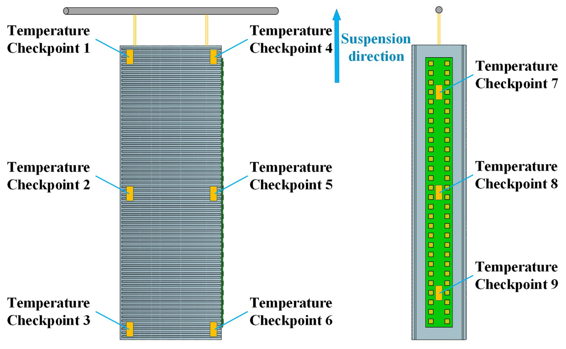
To enable accurate monitoring of the interfacial temperature distribution, six temperature measurement points are deployed on the FAL heat dissipation structure illustrated in Fig. 11, supplemented by three additional monitoring points on the PRS surface. The experiments are performed in a sealed environment maintained at a constant temperature of 30 °C, with temperatures at all measurement points being continuously recorded in real time until the FAL system attained thermal steady-state operation.
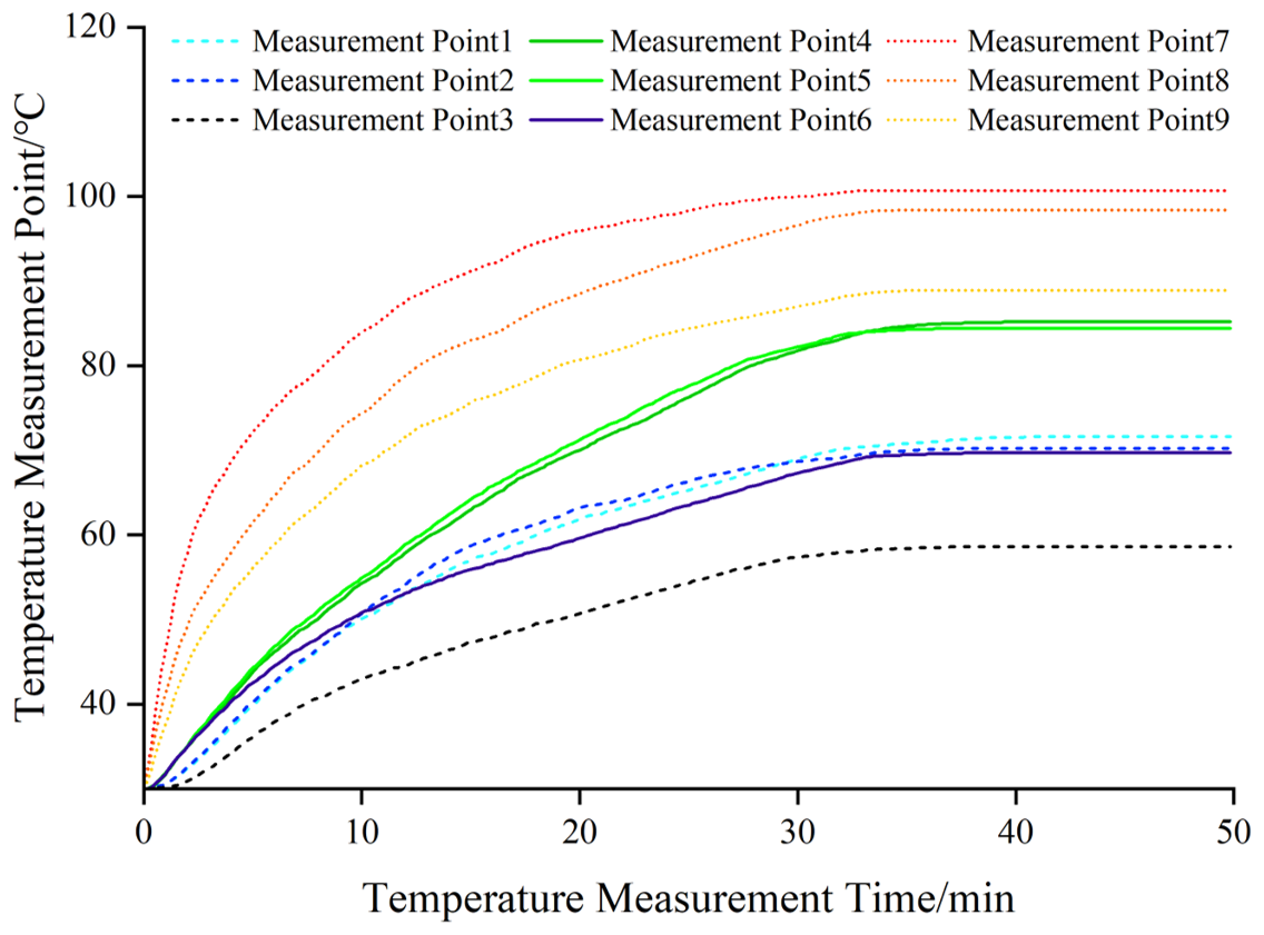
Figure 12Temporal evolution of the FAL interfacial temperature rise at the measurement location.
To further ensure the reliability of the experimental results, three independent replicates are performed under identical operating conditions. The interface temperature acquisition module is configured to automatically record and store data at 10 s intervals, with a single experimental duration of 50 min. This duration is selected to ensure that the FAL system fully reached thermal equilibrium and the temperature rise stabilized. Given that the temperature–time curves obtained from the three experiments exhibited highly consistent trends and the numerical deviations at corresponding measurement points are minimal, the temperature data at the same time instant and measurement location across the three experiments are averaged arithmetically. This approach simplifies data presentation while accurately reflecting the average thermal performance of the test object, yielding the temperature rise curves for each measurement point as shown in Fig. 12.
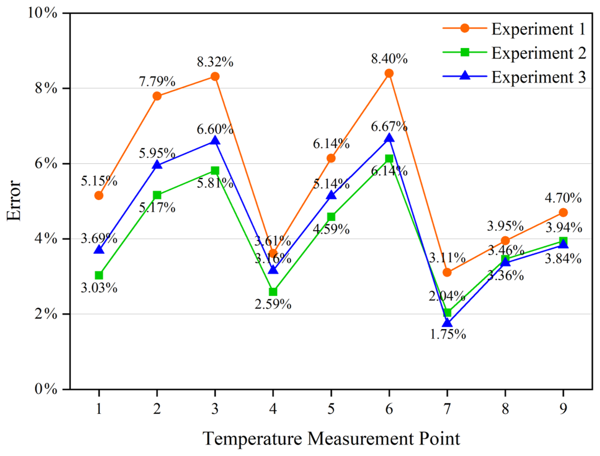
Figure 13Temporal evolution of discrepancy curves between experimental and numerical simulation errors in deep-sea friction-and-lubrication interface measurements.
In Fig. 13, the experimental data and simulation results for the nine interface temperature monitoring points are compared and analysed. Although a certain temperature deviation exists between the experiments and simulations, the relative deviation for all measurement points is within 10 %, indicating good agreement between the two. This level of consistency confirms that the simulation model possesses sufficient computational accuracy and reliability, providing a sound theoretical basis and engineering guidance for the thermal management design of the FAL system.
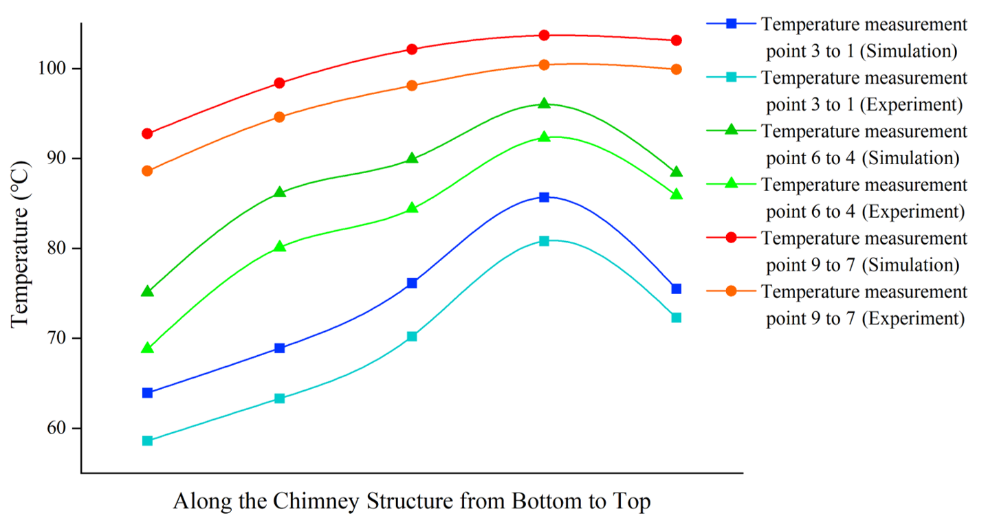
Figure 14Comparison of experimental and simulated interfacial temperature variations along the chimney-shaped FAL structure from bottom to top.
To characterize the temperature distribution along the chimney structure, intermediate monitoring points are added between measurement points 3 and 2 and between points 2 and 1 on the heat dissipation structure away from the PRS side. These points are intended to capture the gradual temperature variation from the chimney bottom to the top. On the side close to the PRS and across the PRS interface region, midpoint sensors are correspondingly installed between points 6 and 5, 5 and 4, 9 and 8, and 8 and 7 to finely resolve the temperature field distribution characteristics on that side and at the interface. The comparison between experimental measurements and numerical simulations is shown in Fig. 14. Although there are some deviations in temperature values at individual measurement points, the overall trend of the FAL temperature rise curve agrees well, thereby validating the reliability of the numerical model.
Heat pipes and surface texturing represent two critical technological pathways for enhancing the thermal performance of micro-element configurations in deep-sea FAL systems. By evaluating highly efficient phase-change heat transfer mechanisms, heat pipes effectively suppress heat accumulation near the heat source, rapidly transporting heat generated by LED chips from the proximal to the distal end of the heat sink, thereby achieving spatial redistribution and complete dissipation of thermal energy. Surface texturing, conversely, augments the effective heat dissipation area and induces turbulent airflow, synergistically intensifying convective heat transfer.
This study systematically evaluates the thermal characteristics of three micro-textured interface configurations through numerical simulation: a baseline configuration without heat pipes or texturing, an improved configuration integrating heat pipes without texturing, and an optimized configuration simultaneously coupling heat pipes with vertically oriented gravity direction grooves. Simulation results demonstrate that heat pipes significantly reduce the temperature gradient between the proximal and distal regions of the heat sink. By alleviating localized thermal accumulation around the heat source, heat pipes enhance the overall convective heat transfer intensity of the FAL system and effectively reduce the junction temperature of LED modules. Furthermore, machining vertical grooves on the heat sink surface periodically disturbs the thermal boundary layer and enhances fluid mixing, thereby promoting more thorough heat exchange between the solid surface and the surrounding air.
The thermal performance of the synergistic optimization design combining heat pipes and vertical surface grooves is further validated through experimental measurements, with results compared against numerical predictions. Although minor deviations exist between experimental temperature data and simulated values, both exhibit excellent consistency in their variation trends, with all relative errors controlled within 10 %.
All relevant data are provided within the manuscript.
Conceptualization: X. G. Wang and X. H. Chen. Methodology: X. G. Wang. Software: J. F. Ruan. Validation: X. G. Wang and X. H. Chen. Formal analysis: X. G. Wang and X. H. Chen. Investigation: J. F. Ruan. Resources: X. H. Chen. Data curation: X. G. Wang and J. F. Ruan. Writing (original draft preparation): X. H. Chen and X. G. Wang. Writing (review and editing): X. G. Wang and X. H. Chen. Visualization: J. F. Ruan. Supervision: J. F. Ruan and X. H. Chen. Project administration: X. H. Chen and X. G. Wang. All of the authors have read and agreed to the published version of the paper.
The contact author has declared that none of the authors has any competing interests.
Publisher's note: Copernicus Publications remains neutral with regard to jurisdictional claims made in the text, published maps, institutional affiliations, or any other geographical representation in this paper. The authors bear the ultimate responsibility for providing appropriate place names. Views expressed in the text are those of the authors and do not necessarily reflect the views of the publisher.
The authors would like to thank the Huaqiao University (HQU) and Chongqing Technology and Business Institute for their support. The authors sincerely appreciate all of the participants for their contributions.
This research was funded by the National Natural Science Foundation Sponsored Project (project approval no. 52475257), the National Key Research and Development Program Project (grant no. 2023YFB3406301), the Fund Project for Technological Field of National Defense Science and Technology Plan 173 (grant nos. 2024-JCJQ-JJ-2020 and 2024-JCJQ-JJ-2043), and the Marine Propulsion Research and Development (MPRD) Program (grant no. MG20220203).
This paper was edited by Zhiwei Zhu and reviewed by three anonymous referees.
Al-Karagoly, M. K. U., Ayani, M. B., Mamourian, M., and Bazaz, S. R.: Experimental parametric study of a deep groove within a pin fin arrays regarding fin thermal resistance, Int. Commun. Heat Mass, 115, 104615, https://doi.org/10.1016/j.icheatmasstransfer.2020.104615, 2020.
Ammosov, L., Mönkkönen, K., and Suvanto, M.: Precise fabrication of microtextured stainless steel surfaces using metal injection moulding, Precision Engineering, 62, 89–94, https://doi.org/10.1016/j.precisioneng.2019.11.012, 2020.
Bai, Y. F., Wang, H., Liu, M. Y., Wu, J. H., Lyu, H. C., and Huang, Y. P.: Direct numerical simulation of flow and heat transfer of supercritical water with different heat fluxes, Int. J. Heat Mass Tran., 221, 125132, https://doi.org/10.1016/j.ijheatmasstransfer.2023.125132, 2024.
Bülbül, H., Atalay, T., Yakut, Y., Özbektaş, S., Köysal, Y.: Investigation of the effect of natural convection cooling caused by the chimney effect on the improved solar thermoelectric system, Appl. Therm. Eng., 263, 125431, https://doi.org/10.1016/j.applthermaleng.2025.125431, 2025.
Duan, Z. J., Xie, G. N., Yu, B., and Jin, P. H.: Multi-objective topology optimization and thermal performance of liquid-cooled microchannel heat sinks with pin fins, Case Studies in Thermal Engineering, 49, 103178, https://doi.org/10.1016/j.csite.2023.103178, 2023.
Eng, Y., Tay, C. M. J., and Khoo, B. C.: Drag and heat transfer in turbulent channel flow over shallow circular dimples: The shift of the deepest point of dimples, Int. J. Therm. Sci., 185, 108049, https://doi.org/10.1016/j.ijthermalsci.2022.108049, 2023.
Firoozeh, S. T., Pourmahmoud, N., and Khalilian, M.: Two-tube heat exchanger with variable groove angle on the inner pipe surface: Experimental study, Appl. Therm. Eng., 234, 121274, https://doi.org/10.1016/j.applthermaleng.2023.121274, 2023.
Gatapova, E. Y., Sahu, G., Khandekar, S., and Hu, R.: Thermal management of high-power LED module with single-phase liquid jet array, Appl. Therm. Eng., 184, 116270, https://doi.org/10.1016/j.applthermaleng.2020.116270, 2021.
Ho, K. C., Wang, S. C., and Liu, Y. H.: Dimming Techniques Focusing; on the Improvement in Luminous Efficiency for High-Brightness LEDs, Electronics, 10, 2163, https://doi.org/10.3390/electronics10172163, 2021.
Hu, T., Xie, L., Chen, J., Huang, Z., and Wang, J.: Numerical study on tribology properties of textured surfaces based on a new contact model, Materials Today Communications, 40, 109969, https://doi.org/10.1016/j.mtcomm.2024.109969, 2024.
Jebali, B., Gennesseaux, M., and Kane, M.: Linking 3D surface texture to frictional performance in steel-rubber contact using a machine learning approach, Interface Topography: Metrology and Properties, 14, 1, 015007, https://doi.org/10.1088/2051-672X/ae38fb, 2026.
Kose, H. A., Yildizeli, A., and Cadirci, S.: Parametric study and optimization of microchannel heat sinks with various shapes, Appl. Therm. Eng., 211, 118368, https://doi.org/10.1016/j.applthermaleng.2022.118368, 2022.
Le, H. S., Galal, A. M., Alhamrouni, I., Mohamed Abbas, A., Saidi, A. S., Truong, T. H., Dahari, M., and Wae-hayee, M.: Heat transfer efficiency optimization of a multi-nozzle micro-channel heat sink utilizing response surface methodology, Case Studies in Thermal Engineering, 37, 102266, https://doi.org/10.1016/j.csite.2022.102266, 2022.
Li, F., Hua, C., and Zhu, Q.: Evaluating the illumination performance of LED fishing lamps with different configurations in Pacific saury fishery, PLOS ONE, 20, e0328676, https://doi.org/10.1371/journal.pone.0328676, 2025.
Li, W., Wang, W., Ren, W., Wu, H., Li, N., and Chen, J.: Microstructure and corrosion properties of Cr41CoFeNi eutectic high-entropy alloy in sulfuric acid solution, J. Alloy. Compd., 978, 173443, https://doi.org/10.1016/j.jallcom.2024.173443, 2024.
Li, X. H., Zhang, L. K., and Li, B. T.: Heat transfer augmentation in microchannel heat sink based on isogeometric topology optimization framework, Appl. Math. Model., 104, 163–187, https://doi.org/10.1016/j.apm.2021.11.021, 2022.
Malika, O., Aumeur E., Choukri, M., and Said, Z.: Experimental investigation on thermal performances of SMD LEDs light bar: Junction-to-case thermal resistance and junction temperature estimation, Optik, 182, 580–586, https://doi.org/10.1016/j.ijleo.2019.01.081, 2019.
Miansari, M., Hasanpour, R., Alizadeh, A., Toghraie, D., and Akbari, O. A.: Numerical analysis of heat transfer enhancement in grooved vertical Multi-Cylinders at various groove geometries, Alexandria Engineering Journal, 70, 535–546, https://doi.org/10.1016/j.aej.2023.02.048, 2023.
Mu, X. K., Sun, W., Liu, C., Wang, Y. L., Yuan, B., and Sun, Q. C.: Study on rough surfaces: A novel method for high-precision simulation and interface contact performances analysis, Precision Engineering, 73, 11–22, https://doi.org/10.1016/j.precisioneng.2021.08.017, 2022.
Nguyen, K. Q., Tran, P. D., Nguyen, L. T., To, P. V., and Morris, C. J.: Use of light-emitting diode (LED) lamps in combination with metal halide (MH) lamps reduce fuel consumption in the Vietnamese purse seine fishery, Aquaculture and Fisheries, 6, 432–440, https://doi.org/10.1016/j.aaf.2020.07.011, 2021.
Nguyen, L. T., Nguyen, T. P., Do, T. V., and Nguyen, K. Q.: Light-emitting diode (LED) lights reduce the fuel consumption and maintain the catch rate of stick-held falling net fisheries, Regional Studies in Marine Science, 55, 102542, https://doi.org/10.1016/j.rsma.2022.102542, 2022.
Ozguc, S., Pan, L., and Weibel, J. A.: Topology optimization of microchannel heat sinks using a homogenization approach, Int. J. Heat Mass Tran., 169, 120896, https://doi.org/10.1016/j.ijheatmasstransfer.2020.120896, 2021.
Ozguc, S., Pan, L., and Weibel, J. A.: Topological optimization of flow-shifting microchannel heat sinks, Int. J. Heat Mass Tran., 207, 123933, https://doi.org/10.1016/j.ijheatmasstransfer.2023.123933, 2023.
Parlak, Z., Parlak, N., and İslamoğlu, Y.: Optimal design of a converging diverging channel for convective heat transfer enhancement in fully developed turbulent air flow, Int. J. Therm. Sci., 161, 106732, https://doi.org/10.1016/j.ijthermalsci.2020.106732, 2021.
Peng, D. S. and Liu, K. L.: Effect of ambient temperature and heating time on high-power LED, J. Phys. Conf. Ser., 1777, The 9th Global Conference on Materials Science and Engineering (CMSE 2020), 20–23 November 2020, Kyiv, Ukraine, 012033, https://doi.org/10.1088/1742-6596/1777/1/012033, 2021.
Rahimi, A., Saee, A. D., Kasaeipoor, A., and Malekshah, E. H.: A comprehensive review on natural convection flow and heat transfer, Int. J. Numer. Method. H, 29, 834–877. https://doi.org/10.1108/HFF-06-2018-0272, 2018.
Ruan, J., Wang, X., Wang, Y., and Zou, W.: Mask-guided microbial jet machining: An approach for fabricating functionalized textured interfaces, J. Tribol.-T. ASME, 147, 124205, https://doi.org/10.1115/1.4069248, 2025.
Velardo, J., Date, A., Singh, R., Nihill, J., Date, A., Phan, T. L., and Takahashi, M.: Experimental investigation of a vapour chamber heat spreader with hybrid wick structure, Int. J. Therm. Sci., 140, 28–35, https://doi.org/10.1016/j.ijthermalsci.2019.02.009, 2019.
Wang, Z., Chen, G., Wen, M., Hu, X., Liu, X., Wei, J., Wu, Q., and Fu, Y.: Electrochemical strategy for high-resolution nanostructures in laser-heat-mode resist toward next generation diffractive optical elements, Small, 18, 2200249, https://doi.org/10.1002/smll.202200249, 2022.
Xiong, J., Zhang, L., Yu, L., Dai, J., and Lv, Q.: Using laser etched-array periodic structure surface to construct silver loaded titanium implants with combined efficient antib acterial and osteogenic properties, Appl. Surf. Sci., 641, 158533, https://doi.org/10.1016/j.apsusc.2023.158533, 2023.
Yan, J., Xu, Q., Fan, Z., Geng, D., Niu, B., and Duan, Z.: A study on topology optimization of heat dissipation structures with different objective functions based on an explicit moving morphable components method, Eng. Optimiz., 55, 1336–1351, https://doi.org/10.1080/0305215X.2022.2086236, 2023.
Yang, P., Wang, L., Qing, T., and Liu, Y. W.: Multi-objective optimization of geometrical parameters of laterally perforated on silt fin by gray relation analysis based on Taguchi method, Int. J. Therm. Sci., 196, 108705, https://doi.org/10.1016/j.ijthermalsci.2023.108705, 2024.
Yang, Y. X., Wang, Z. C., Li, X. F., Zhao, D., Zuo, J., Ren, Y. J., Lyu, W. H., and Xu, Z. W.: Investigating the impact of stack effect on ventilation performance of residential kitchen exhaust shaft system, Energ. Buildings, 296, 113364, https://doi.org/10.1016/j.enbuild.2023.113364, 2023.
Zhang, J. Z., Xu, J. J., An, J., Chen, J. X., Liu, Y., Zhou, Q., Pan, H. F., and Xin, G. M.: Multi objective optimization of manifold microchannel heat sink with staggered microchannels, Int. Commun. Heat Mass, 159, 108106, https://doi.org/10.1016/j.icheatmasstransfer.2024.108106, 2024.
Zhang, Y., Huang, X. H., Chen, X. J., Liu, B. L., Kong, X. H., and Deng, Q. K.: Optimal configuration and three-dimensional light field of fishing lights on a squid fishing boat obtained using a space matrix algorithm, Fish. Res., 281, 107223, https://doi.org/10.1016/j.fishres.2024.107223 2025.
Zhou, J. Z., Zhao, X. D., Yuan,Y. P., Fan, Y., and Li, J.: Mathematical and experimental evaluation of a mini-channel PV/T and thermal panel in summer mode, Sol. Energy, 224, 401–410, https://doi.org/10.1016/j.solener.2021.05.096, 2021.
- Abstract
- Introduction
- Topology optimization of chimney-effect-enhanced heat dissipation configurations
- Topology optimization and simulation analysis
- Comparative simulation analysis of surface texture micro-element configurations for the proposed FAL model
- Optimization analysis of multi-scale configuration parameters for surface micro-textures
- Comparison and mechanistic analysis of thermal simulation results
- Comparison of simulation and experimental results
- Conclusion
- Data availability
- Author contributions
- Competing interests
- Disclaimer
- Acknowledgements
- Financial support
- Review statement
- References
- Abstract
- Introduction
- Topology optimization of chimney-effect-enhanced heat dissipation configurations
- Topology optimization and simulation analysis
- Comparative simulation analysis of surface texture micro-element configurations for the proposed FAL model
- Optimization analysis of multi-scale configuration parameters for surface micro-textures
- Comparison and mechanistic analysis of thermal simulation results
- Comparison of simulation and experimental results
- Conclusion
- Data availability
- Author contributions
- Competing interests
- Disclaimer
- Acknowledgements
- Financial support
- Review statement
- References