the Creative Commons Attribution 4.0 License.
the Creative Commons Attribution 4.0 License.
 | 22 Sep 2026
Analysis of the influence of magnetic field on polishing results in reciprocating magnetorheological polishing
Rensheng Wang

Dongming Liang
Xiangna Kong
Qi Wang
In this paper, a magnetic field device applicable to reciprocating magnetorheological polishing (RMRP) is designed, and the influence of excitation current as well as working gap on the device's magnetic field performance is systematically studied. Specifically, the structure of the RMRP magnetic field device is configured and elaborated in detail, and a series of magnetic field simulations are further employed to analyze the variations in magnetic induction intensity within the polishing area induced by excitation current and working gap. In addition, RMRP experiments are conducted to evaluate how excitation current and working gap affect the final polishing results. The simulation results for the magnetic field device indicate that magnetic induction intensity in the polishing area is positively correlated with excitation current, yet negatively correlated with the working gap. When either the excitation current or the working gap is held constant, the magnetic induction intensity within the polishing area exhibits a non-monotonic trend of initial increase followed by decrease as radial distance increases. The RMRP experimental results demonstrate that at an excitation current of 4 A, the surface roughness of the specimen is reduced significantly, dropping from an initial 327 nm to a final 42 nm. Correspondingly, when the working gap is adjusted to 0.75 mm, the surface roughness of the specimen decreases from 322 to 41 nm.
- Article
(5484 KB) - Full-text XML
- BibTeX
- EndNote


Characterized as an advanced ultra-smooth polishing technique, magnetorheological polishing (MRP) enables high-efficiency, damage-free subsurface improvement of the machining precision and surface quality of components with complex geometries (Kim et al., 2018; Wang et al., 2021; Pan et al., 2019; Lu et al., 2024). Operating on the following principle, MRP achieves surface material removal of specimens through a tailored physical process: when a magnetic field is applied, ferromagnetic particles dispersed in MRP fluids are magnetized immediately and align into regular magnetic chains along magnetic induction lines, with polishing abrasives subsequently being clamped in the ordered chains to form a multi-point flexible magnetic polishing brush that comes into contact with the specimen surface (Wang et al., 2023; Khan and Jha, 2018; Kumar et al., 2021; Wang et al., 2024). It is evident that magnetic field parameters constitute a critical factor governing the polishing performance, and numerous researchers have consequently conducted extensive investigations into this aspect of MRP. Wang et al. (2016) designed a permanent magnetic (PM) yoke featuring a straight air gap for MRP equipment, which is capable of polishing relatively large flat surfaces while achieving desirable surface quality. Luo et al. (2018) adopted a magnetic permanent yoke structure as the magnetic field generator for the MRP of zirconia ceramics. Trinh et al. (2025) used multipole magnetic yokes for high-stability, high-efficiency MRP of SiC materials. Although the magnetic yoke structure can effectively provide the magnetic induction intensity in the processing area through the leakage magnetic principle, the processing area is limited and is not suitable for processing large-sized workpieces. Furthermore, the permanent magnet yoke cannot adjust the magnetic induction intensity in the polishing area. Sato et al. (2013) developed a rapid-MRP device equipped with a double-magnetic tool consisting of two permanent ring magnets with opposite polarities. This configuration not only inhibits magnetic flux leakage outside the polishing area but also contributes to the generation of a higher magnetic induction intensity within the working area. Pan and Yan (2015) proposed a clustered magnetorheological (MR) planar polishing system, which is based on the regular arrangement of magnets and tailored for large planar optical specimens. Parameswari et al. (2019) investigated the application of a multi-magnet configuration in MRP systems, aiming to produce intensified magnetic fields suitable for processing large-scale specimens. Nie et al. (2019) studied the relationship between the arrangement of magnets and the distribution of magnetic induction intensity, and analyzed the effects of different magnet distribution patterns on polishing. Guo et al. (2022) proposed an innovative high-efficiency MRP process that utilizes a Halbach array as the magnetic field excitation source to expand the magnetic field range and enhance MRP efficiency. Reasonable arrangement of magnets can effectively expand the magnetic path coverage area within the polishing zone. However, too many magnetic poles will increase the size of the magnetic field generating device, which will have a certain impact on the spatial layout of the polishing device. In addition, the use of permanent magnetic fields has the problem that the magnetic induction intensity is difficult to adjust in real time.
As mentioned above, for the processing requirements of large-scale workpieces, an ideal magnetic field generation device not only needs to be compatible with the overall space layout of the polishing equipment but also provide a magnetic field environment featuring wide magnetic circuit coverage, high magnetic induction intensity and real-time magnetic field adjustability within the polishing area. The primary objective of this research is to design a dynamic magnetic field device tailored for the polishing of large-scale specimens. This device can provide a controllable magnetic field with high magnetic induction intensity in the polishing area. By changing the position of the magnetic field, it not only facilitates the full-scale processing of the workpiece but also promotes continuous replenishment of MRP fluids on the polishing area, thereby effectively improving the surface quality of polished workpiece. The magnetic induction intensity is jointly determined by the magnetomotive force and total reluctance of the magnetic circuits. The excitation current actively adjusts the magnetic field by controlling the magnetomotive force, while variations in the working gap size can significantly alter the total magnetic circuit reluctance. Based on electromagnetic principles and practical operability, a set of magnetic field simulation is performed to investigate how excitation current and working gap influence the magnetic induction intensity in the polishing area. Furthermore, the effects of these two parameters on the polishing results are studied by the RMRP experiments.
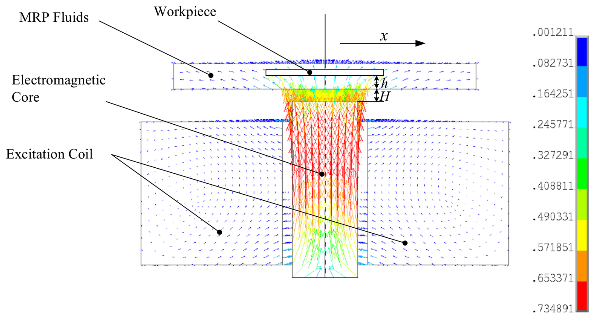
In this work, the RMRP method is adopted, which is characterized by a dynamic single-pole reciprocating magnetic field (see Fig. 1) (Wang et al., 2022a). H is the distance between the upper surface of the electromagnet core and the working surface of the fluids carrier, which is equal to the thickness of the bottom surface of the fluids carrier plus the distance from the electromagnet core's upper surface to the fluids carrier's lower surface. h is the working gap. The RMRP method operates on the principle that the Bingham magnetic polishing brush, formed when MRP fluids are subjected to a magnetic field, moves synchronously with the field, which in turn allows the brush to achieve full-area machining of the specimen through continuous changes in its position. Meanwhile, the reciprocating motion of the magnetic field applies a consistent polishing force to different areas of the specimen, which is conducive to achieving uniform machining effects. What is more, the magnetic field device designed for RMRP is structurally simple and facilitates the continuous replacement of MRP fluids in the polishing region, an essential factor in ensuring reliable specimen machining quality (Wang et al., 2022b).
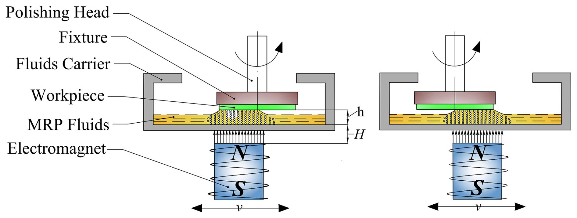
The design of this magnetic field device adopts an open single-pole magnetic field circuit, which can form a large magnetic circuit coverage range to meet the requirement of covering the specimen with a large area of magnetic circuit, and it is mainly composed of the electromagnetic core, excitation coil and coil skeleton. Figure 2 schematically depicts the magnetic field device utilized for the RMRP experiments.
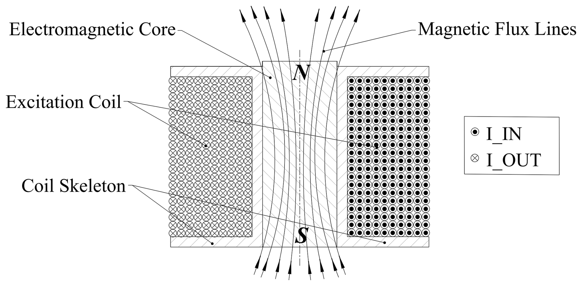
Soft magnetic material with high relative permeability, low coercivity and easy magnetization and demagnetization is selected as the electromagnetic core, which is installed in the plastic coil skeleton. To meet the above-stated requirements, electrical pure iron DT4 is designated as the electromagnetic core component of the magnetic field device, and non-magnetic material, such as engineering plastics, is selected as the coil skeleton of the magnetic field device. The electromagnetic core is cylindrical, measuring 26 mm in diameter and 70 mm in height, while the excitation coil is configured with a wire diameter of 1.2 mm and a total of 2200 turns. In order to provide sufficient magnetic induction intensity in the polishing area and reduce the attenuation of the magnetic field, the distance between the magnetic pole surface and the specimen surface should be considered. The outer side of the coil skeleton is evenly wound with the excitation coil, which is connected with the external DC power supply, and the magnetic induction intensity produced by this magnetic field device is governed by varying the magnitude of the applied current.
In the process of MRP, the magnetic polishing brush is greatly affected by the magnetic field, and the magnetic induction intensity plays an important role in determining the polishing force. Therefore, the reasonable control of magnetic induction intensity distribution and value is an important part of the specimen processing quality.
The magnetic induction intensity B at any point on the axis of the magnetic field device in the air gap can be estimated without considering the permeability of base medium as follows (Jha and Jain, 2006; Das et al., 2008):
where r1, r2 and L are inner radius, outer radius and length of the solenoid, respectively. μ0 is vacuum permeability, n stands for the excitation coil turns per unit length, I is the current in the excitation coil and l is the distance from pole surface on the axis of the magnetic field device (, as seen in Fig. 1).
It can be observed from Eq. (1) that in addition to the excitation current I and working gap h, the magnetic induction intensity is also influenced by multiple process parameters such as magnetic material, excitation coil turns and structural dimensions. However, most of these parameters are fixed by the structural design of the device. In contrast, the excitation current and working gap can be independently adjusted during equipment operation as core controllable variables for magnetic performance optimization. Thus, further analysis is still needed for these two key variables.
Given the axisymmetric structure of the magnetic field device, ANSYS software is employed in this study to perform two-dimensional magnetostatic field simulation. The primary objective of this simulation is to determine the magnitude and spatial distribution of magnetic induction intensity in the specimen polishing area, with a specific focus on the two key process parameters of the excitation current and working gap.
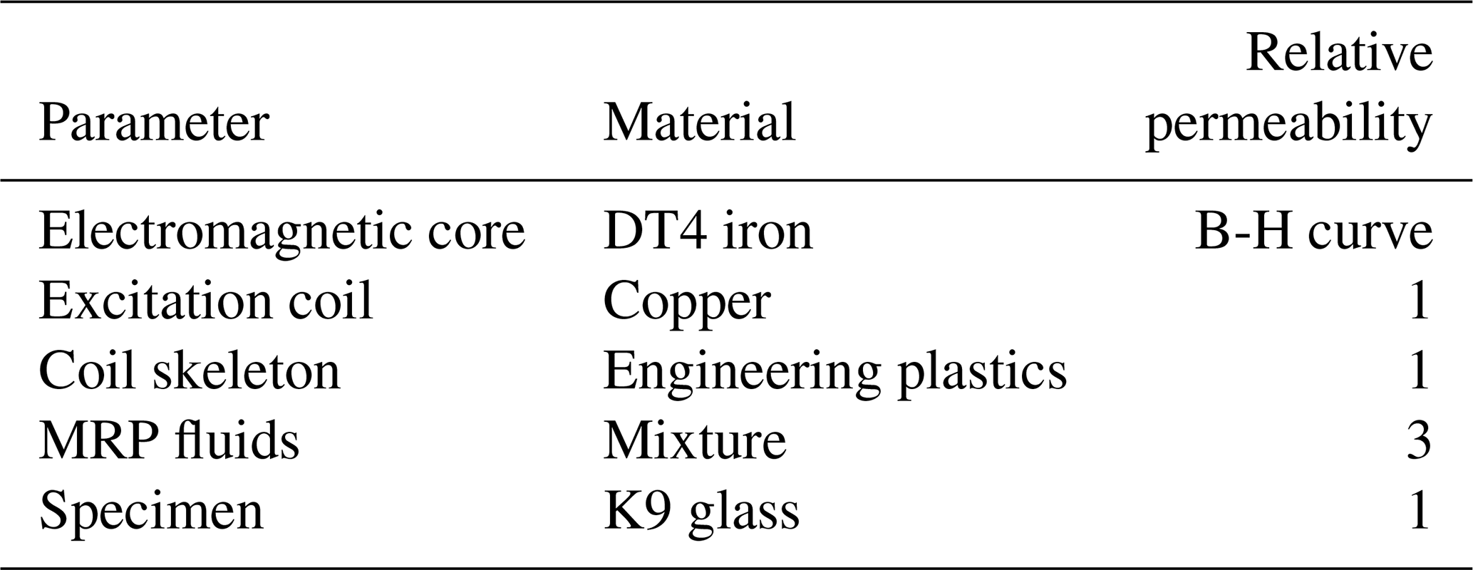
Material parameters utilized in the simulation are specified in Table 1. The simulation is conducted across two key process parameters known to influence magnetic induction intensity: excitation current, varied from 1 to 5 A in 1 A increments, and working gap, adjusted from 0.25 to 1.5 mm with a step size of 0.25 mm. The selection range of each parameter is determined to satisfy the requirement that the target magnetic induction intensity can be obtained in the polishing area. An excessively high excitation current will result in overheating of the excitation coil; if the working gap is set too large, the magnetic field on the polishing area will decay rapidly and fail to reach the processing-required magnetic induction intensity. The parameter ranges selected in this paper are consistent with the values reported in existing similar literature (Khatri et al., 2018; Singh et al., 2012), which can ensure that the test results have good comparability and repeatability. At an excitation current of 3 A and a working gap of 0 mm, a magnetostatic simulation is performed to characterize the magnetic induction intensity over the MRP fluids, and the resulting magnetic induction lines are presented in Fig. 3. It clearly shows that the magnetic induction lines form symmetrical closed-loop structures along the electromagnet's centerline, and the variation in magnetic induction intensity along the ±x direction follows a pattern of initial increase followed by decrease. The distribution of magnetic inductance lines is like a petal structure because the magnetic circuit preferentially passes through MRP fluids units with higher relative permeability. Moreover, as shown in Fig. 3, the physical meanings and graphic labeling forms of parameters H and h are completely consistent with those in Fig. 1, mentioned above. The parameter x is defined as the radial direction along the surface of the electromagnet core.
3.1 Excitation current
According to Ampere's circuital law, the magnetic induction intensity is determined by both the excitation current and the number of excitation coil turns (B∝nI), demonstrating that coil turns exert a considerable effect on the magnetic induction intensity. However, a fixed excitation coil with 2200 turns is adopted for all experiments in this work. The number of excitation coil turns is kept constant to exclude additional interference variables, since the core objective of this study is to investigate the influence of excitation current on the magnetic induction intensity.
Building on the above analysis, with the working gap fixed at 0 mm, the excitation coil configured with 2200 turns and all other simulation parameters held constant, different current intensity are applied to investigate the influence of current on the magnetic induction intensity in the polishing area. Given the specimen dimension (15 mm radius), a radial distance range of 0–21 mm is selected to ensure comprehensive coverage of the polished specimen area for magnetic induction intensity analysis. The relationship between current parameters and magnetic induction intensity is illustrated in Fig. 4.
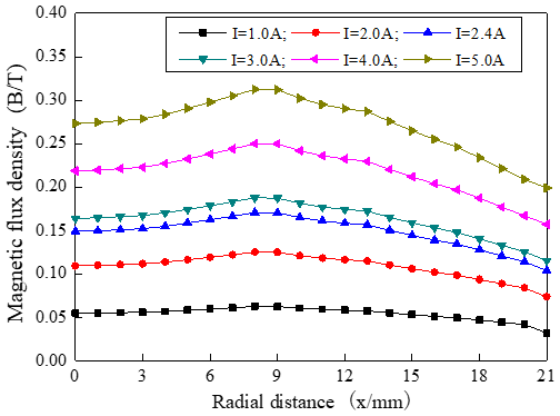
Figure 4Relationship between current parameters and magnetic induction intensity in the polishing area.
It is evident from the data that magnetic induction intensity in the polishing area exhibits a positive correlation with current intensity. When the excitation current is set to 1 A, the maximum magnetic induction intensity is below 0.1 T, which cannot meet the magnetic induction intensity required for material removal. This is because under a weaker magnetic field, the ferromagnetic particles in MRP fluids either fail to form chains or the resulting chains possess insufficient yield strength. No effective magnetic chains required for material removal can be established to clamp polishing abrasives, resulting in limited improvement in the workpiece surface roughness (Souza et al., 2022). When the excitation current is 2 A or higher, the maximum magnetic induction intensity exceeds 0.1 T, which can meet the magnetic induction intensity required for material removal. In addition, at a constant current intensity, the magnetic induction intensity within the polishing area exhibits a trend of first increasing and then decreasing as the radial distance increases, and it is more obvious with the increase in current intensity.
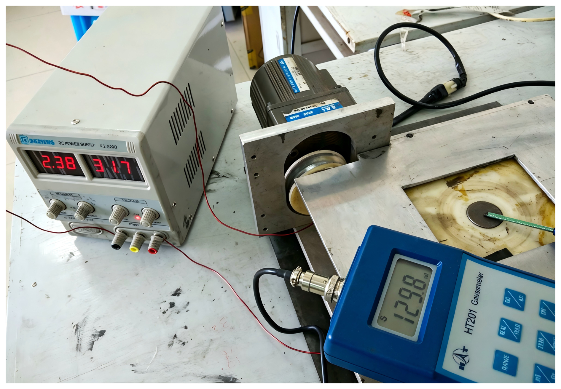
An excitation current of 2.4 A is applied to the electromagnet. The radial displacement on the surface of the electromagnet core is defined as the measurement path (the x direction shown in Fig. 3). Eight measuring points with a step interval of 3 mm are arranged along this measurement path. A contact measurement scheme is adopted where the probe of a gauss meter is closely attached to the surface of the electromagnet core to measure magnetic induction intensity so as to verify the accuracy of the magnetic field simulation, as presented in Fig. 5. Comparative analysis of simulated and measured data reveals that the magnetic induction intensity increases first and then decreases as the radial displacement grows. The value of the error is within 12.4 %, which verifies the consistency between simulation and measurement results, as illustrated in Fig. 6.
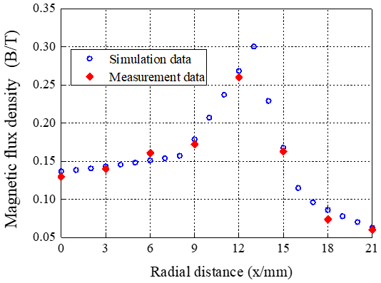
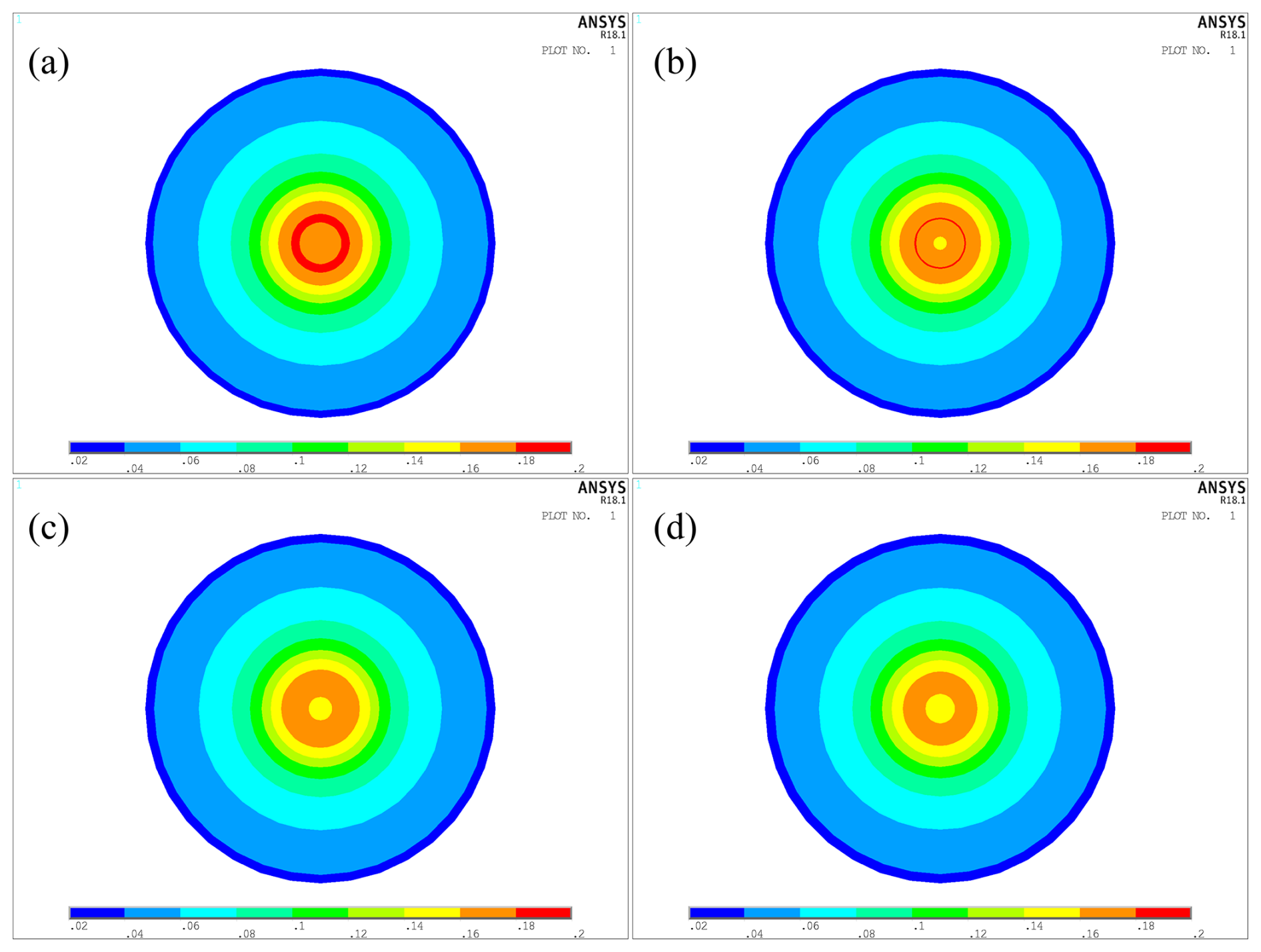
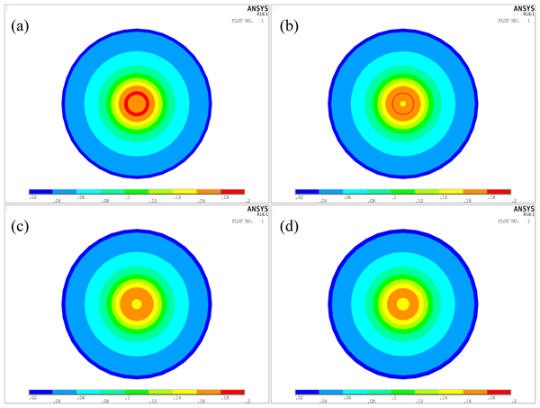
Figure 7Slice map of the magnetic field simulation: (a) h=0.50 mm, (b) h=0.75 mm, (c) h=1.00 mm, (d) h=1.25 mm.
3.2 Working gap
In the course of magnetic field analysis, apart from the impact of the excitation current on magnetic induction intensity, the working gap represents another key influencing factor. Therefore, it is important to consider the magnetic field analysis of various working gap. When the excitation current is set to 3 A, the excitation coil has 2200 turns and other simulation parameters also remain unchanged, the slice map of the magnetic field simulation is made under the same nephogram scale and different working gap, as illustrated in Fig. 7. It is clear that a narrower working gap corresponds to a higher average magnetic induction intensity in the slice map. This is because a reduced working gap drastically lowers the air-gap reluctance and increases magnetic flux. With a constant cross-sectional area, the magnetic induction intensity rises, which in turn translates to a higher average magnetic induction intensity in the specimen polishing area. Figure 8 demonstrates the correlation between working gap and magnetic induction intensity. It is observed that the peak magnetic induction intensity corresponding to the polishing area slice map decreases with the expansion of the working gap. As the radial distance increases, the magnetic induction intensity of the polishing area slice map exhibits a trend of rising first and then declining, which is similar to the case of loading different excitation current mentioned above. However, the slope of the curves rises and falls more sharply, which indicates that the effect of the working gap on magnetic induction intensity is more significant than that of the excitation current.
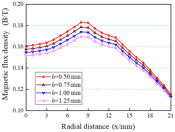
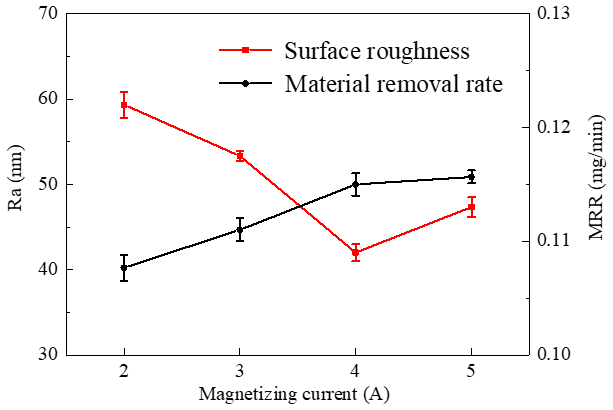
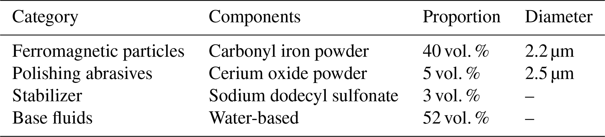
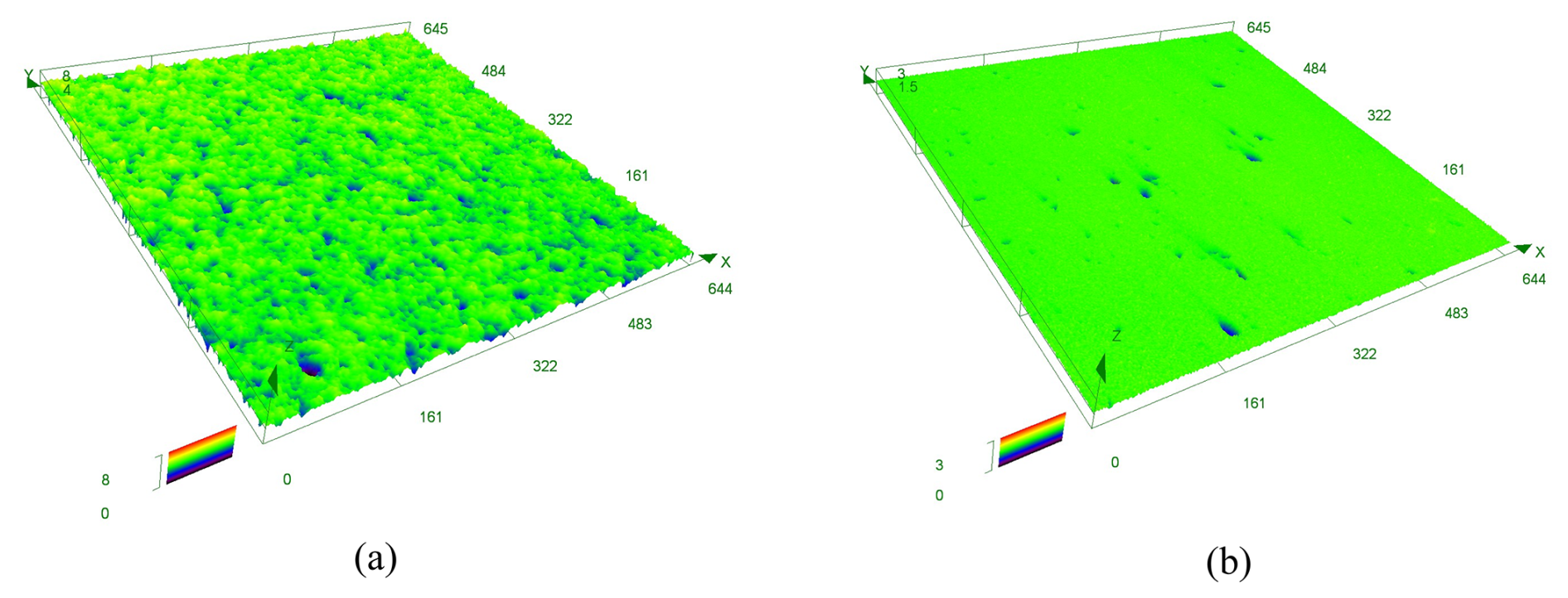
Figure 10Micromorphologies of the workpiece surface: (a) initial surface morphology, (b) polished surface morphology (I=4 A).
The MRP fluids serve as the core medium of the MRP process, and their comprehensive performance directly determines the final polishing quality of the workpiece. The polishing fluids mainly consist of four components: ferromagnetic particles, polishing abrasives, stabilizer and base fluids. These components are uniformly mixed according to a specific mass or volume fraction. The key characteristic parameters of the MRP fluids used in this study are derived from Wang et al. (2022b), and the detailed values are presented in Table 2. K9 optical glass, a borosilicate material with uniform light transmittance and stable physicochemical properties, is selected as the experimental workpiece. This material is widely adopted as a common substrate for optoelectronic systems, microwave components and precision optical elements. The specimen dimensions are Φ30 mm × 8 mm, and the initial surface roughness measured after preprocessing prior to polishing ranges from 320 to 340 nm.
4.1 The dependence of RMRP polishing results on excitation current
This study implements multiple groups of experiments to examine the correlation between excitation current and polishing results. Specifically, the specimen is rotated at 300 r min−1 while the eccentric wheel runs at 20 r min−1; additionally, the working gap is maintained at 0.75 mm and the polishing process lasts for 45 min. The correlation between excitation current and polishing results is presented in Fig. 9.
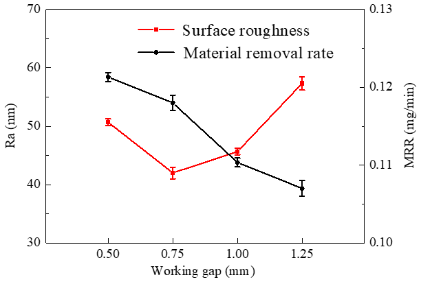
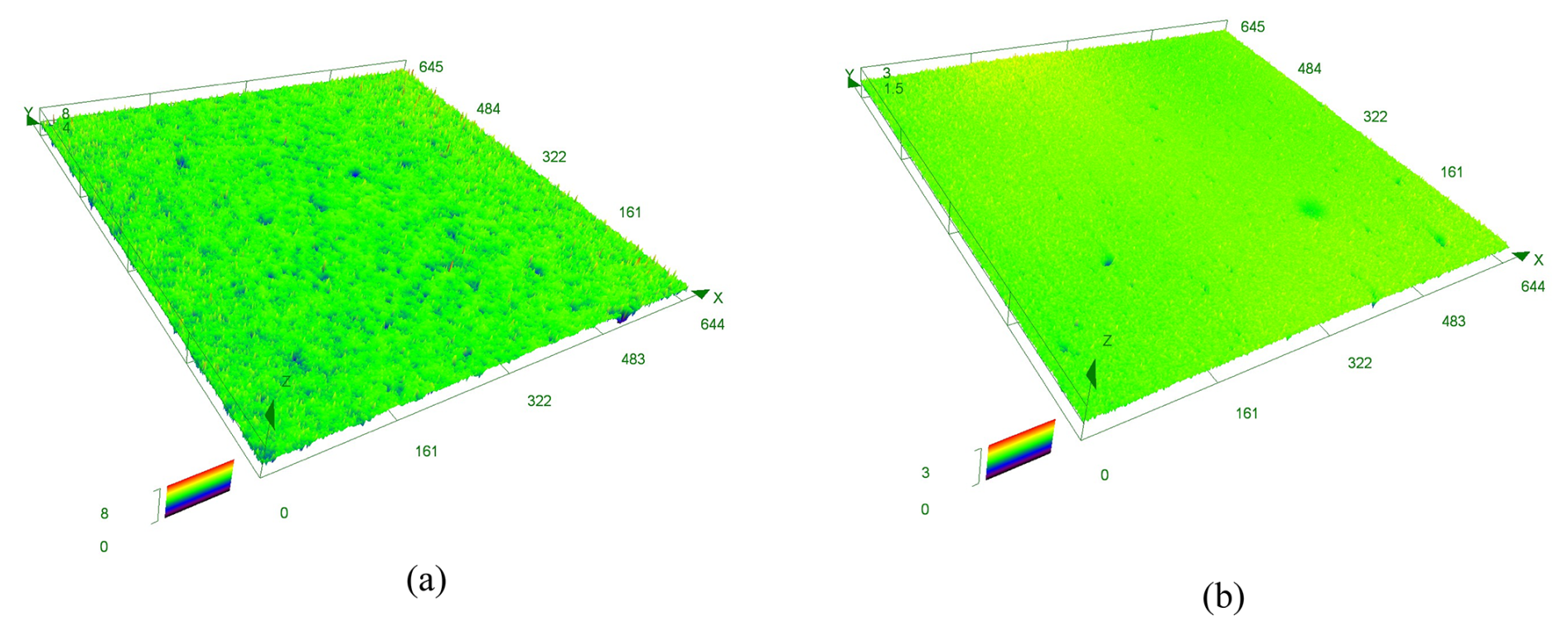
Figure 12Micromorphologies of the workpiece surface: (a) initial surface morphology, (b) polished surface morphology (h=0.75 mm).
To ensure the reliability of experimental data, three independent replicate tests are performed for each group of processing parameters. After each polishing is completed, the surface roughness and material removal rate (MRR) of the specimen are measured and calculated. Standard deviation (SD) is used to quantify the dispersion of measured data and is presented as error bars in the graphs to visually illustrate the measurement fluctuation in the data in each group. One-way analysis of variance (one-way ANOVA) is adopted for statistical significance analysis based on the three repeated measurements of each group. The results reveal that variations in the independent variable exert statistically significant effects on both surface roughness and MRR (P<0.05). Figure 9 clearly demonstrates that the MRR exhibits an upward trend with the increasing excitation current. This phenomenon occurs due to a direct correlation of magnetic induction intensity with the excitation current, as stated in Eq. (1), with all other parameters maintained at constant values. An increase in the excitation current gives rise to a marked elevation in magnetic induction intensity. Thus, the magnetic chains within the polishing brush experience a distinct rise in strength, and the polishing particles' binding force is further enhanced, thereby increasing the efficiency of the polishing abrasives in removing the surface material of the specimen. In other words, the MRR of the specimen is improved. In general, an increase in MRR is anticipated to bring about a corresponding reduction in surface roughness. Nevertheless, it is observed that surface roughness increases when the excitation current is in the range of 4 to 5 A. This phenomenon can be ascribed to the enhanced shear yield strength of the polishing brush under higher excitation currents, and this effect imposes stronger constraints on the polishing abrasives to bring them closer to the behavior of fixed abrasives. On the one hand, the efficiency of the machining process is enhanced; on the other hand, the potential for surface damage to the specimen can result in a slight increase in its roughness. It can be seen that the optimal processing parameter is when the excitation current is 4 A, and the surface roughness decreases substantially, dropping from 327 nm down to 42 nm. Figure 10 compares the surface micromorphology between the initial workpiece and the workpiece polished by RMRP. It can be observed that the workpiece surface becomes flat, smooth and uniform after polishing, with a remarkable improvement in surface machining quality.
4.2 The dependence of RMRP polishing results on working gap
Similarly, a series of experiments are carried out with different working gaps selected. In these tests, the working gap is set as the variable, while other parameters (including an excitation current of 4 A) are kept constant. Error analysis and one-way ANOVA are performed for data evaluation, and the obtained conclusions are consistent with the above findings, as detailed in Sect. 4.1.
As illustrated in Fig. 11, the specimen's MRR exhibits a decreasing trend with an increase in the working gap. The underlying reason is that magnetic induction intensity is directly related to working gap when all other parameters remain unchanged, as specified in Eq. (1). This occurs because an increase in the working gap leads to a reduction in the magnetic induction intensity of the polishing area, which in turn weakens the binding effect on the polishing abrasives. Moreover, the polishing abrasives' ability to remove material from the specimen surface is reduced. On the other hand, with the increase in the working gap, the surface roughness of the specimen decreases initially before rising subsequently. The reason lies in the fact that a narrower working gap corresponds to a higher magnetic induction intensity, and the polishing particles are bound by the magnetic chains, which forms characteristics similar to those of fixed abrasives. This may induce damage to the specimen surface, thereby causing the surface roughness of the specimen to rise. Conversely, a larger machining gap leads to a decrease in the specimen's MRR and a subsequent increase in its surface roughness. Based on these results, the optimal processing parameter is determined to be a working gap of 0.75 mm, which achieves a reduction in surface roughness from 322 to 41 nm. The surface micromorphology of the workpiece before and after RMRP is shown in Fig. 12. The polished workpiece surface is flatter, more uniform and smoother, and its surface quality is substantially enhanced.
In this paper, a novel dynamic magnetic excitation device for MRP of large-sized workpieces is proposed. It generates controllable magnetic fields with wide coverage and high magnetic induction intensity, dynamically renews MRP fluids and effectively improves workpiece surface quality. Unlike bulky magnet arrays (magnetic yokes) with non-adjustable magnetic induction intensity, the proposed structure realizes both compact device layout and real-time magnetic field regulation, possessing prominent innovations and promising application prospects for ultra-precision machining of optical components. Combined with simulation analysis and experimental tests, the main conclusions are summarized as follows:
-
The developed dynamic magnetic excitation device can form magnetic fields with wide coverage and adjustable high flux density, and continuously refresh polishing fluids during processing. It overcomes the inherent defects of traditional magnetic structures and possesses outstanding innovation and engineering value for ultra-precision polishing.
-
The magnetic induction intensity within the polishing area rises with the increase in the excitation current. At a fixed excitation current, the magnetic induction intensity first increases and then decreases as the radial distance expands. The maximum magnetic induction intensity of the polishing area slice map decreases with the increase in the working gap. Similarly, under a fixed working gap, the magnetic induction intensity of the polishing area slice map follows a trend of initial increase and then decrease with the increase in radial distance. Notably, magnetic induction intensity is more sensitive to changes in the working gap than excitation current.
-
To obtain better specimen polishing results, the values of the excitation current and working gap should be reasonably selected. The optimized process parameters are determined as an excitation current of 4 A and a working gap of 0.75 mm, which reduce the surface roughness of the specimen from an initial value of approximately 325 to 42 nm and 41 nm, respectively.
All of the code used in this article can be obtained from the corresponding author.
All the data used in this article can be obtained from the corresponding author.
RW designed and conducted this study, carried out the related work and used software for simulation. DL and XK wrote the initial draft. QW assisted in data collection and experimental operations. RW supervised the research and revised the article. All authors have reviewed and approved the final article.
The contact author has declared that none of the authors has any competing interests.
Publisher's note: Copernicus Publications remains neutral with regard to jurisdictional claims made in the text, published maps, institutional affiliations, or any other geographical representation in this paper. The authors bear the ultimate responsibility for providing appropriate place names. Views expressed in the text are those of the authors and do not necessarily reflect the views of the publisher.
The authors acknowledge the financial support of the Liaoning Provincial Department of Education and Yingkou Municipal Bureau of Science and Technology.
This paper was edited by Jia Ge and reviewed by two anonymous referees.
This research was funded by the Liaoning Province Education Department Project of China (grant no. 2024JYTKYPT-01) and the Yingkou City Double Innovation Plan Project of China.
Das, M., Jain, V. K., and Ghoshdastidar, P. S.: Analysis of magnetorheological abrasive flow finishing (MRAFF) process, Int. J. Adv. Manuf. Tech., 38, 613–621, https://doi.org/10.1007/s00170-007-1095-8, 2008.
Guo, Y., Yin, S., Ohmori, H., Li, M., Chen, F., and Huang, S.: A novel high efficiency magnetorheological polishing process excited by Halbach array magnetic field, Precis. Eng., 74, 175–185, https://doi.org/10.1016/j.precisioneng.2021.11.011, 2022.
Jha, S. and Jain, V. K.: Modeling and simulation of surface roughness in magnetorheological abrasive flow finishing (MRAFF) process, Wear, 261, 856–866, https://doi.org/10.1016/j.wear.2006.01.043, 2006.
Khan, D. A. and Jha, S.: Synthesis of polishing fluid and novel approach for nanofinishing of copper using ball-end magnetorheological finishing process, Mater. Manuf. Processes, 33, 1150–1159, 2018.
Khatri, N., Tewary, S., Manoj, X. J., Garg, H., and Karar, V.: Magnetorheological finishing of silicon for nanometric surface generation: an experimental and simulation study, J. Intell. Mater. Syst. Struct., 29, 2456–2464, 2018.
Kim, B. C., Chung, J. H., Cho, M. W., Ha, S. J., and Yoon, G.-S.: Magnetorheological fluid polishing using an electromagnet with straight pole-piece for improving material removal rate, J. Mech. Sci. Technol., 32, 3345–3350, 2018.
Kumar, M., Yadav, H., Kumar, A., and Das, M.: An overview of magnetorheological polishing fluid applied in nano-finishing of components, J. Micromanuf., 5, 82–100, https://doi.org/10.1177/25165984211008173, 2022.
Lu, M.-M., Yang, Y.-K., Lin, J.-Q., Du, Y.-S., and Zhou, X.-Q.: Research progress of magnetorheological polishing technology: a review, Adv. Manufact., 12, 642–678, 2024.
Luo, H., Guo, M., Yin, S., Chen, F., Huang, S., Lu, A., and Guo, Y.: An atomic-scale and high efficiency finishing method of zirconia ceramics by using magnetorheological finishing, Appl. Surf. Sci., 444, 569–577, 2018.
Nie, M., Cao, J., Li, J., and Fu, M.: Magnet arrangements in a magnetic field generator for magnetorheological finishing, Int. J. Mech. Sci., 161, 105018, https://doi.org/10.1016/j.ijmecsci.2019.105018, 2019.
Pan, J. and Yan, Q.: Material removal mechanism of cluster magnetorheological effect in plane polishing, Int. J. Adv. Manuf. Tech., 1–10, https://doi.org/10.1007/s00170-015-7332-7, 2015.
Pan, J., Guo, M., Yan, Q., Zheng, K., and Xiao, X.: Research on material removal model and processing parameters of cluster magnetorheological finishing with dynamic magnetic fields, Int. J. Adv. Manuf. Tech., 100, 2283–2297, 2019.
Parameswari, G., Jain, V., Ramkumar, J., and Nagdeve, L.: Experimental investigations into nanofinishing of Ti6Al4V flat disc using magnetorheological finishing process, Int. J. Adv. Manuf. Tech., 100, 1055–1065, 2019.
Sato, T., Kum, C. W., and Venkatesh, V.: Rapid magneto-rheological finishing of Ti-6Al-4V for aerospace components, Int. J. Nanomanufact. 3, 431–445, 2013.
Singh, A. K., Jha, S., and Pandey, P. M.: Parametric analysis of an improved ball end magnetorheological finishing process, P. I. Mech. Eng. B-J. Eng., 226, 1550–1563, 2012.
Souza, A. M., Silva, E. J. d., Ratay, J., and Yamaguchi, H.: Magnetic field-assisted finishing processes: from bibliometric analysis to future trends, J. Braz. Soc. Mech. Sci. Eng., 44, https://doi.org/10.1007/s40430-022-03641-5, 2022.
Trinh, N. D., Van Thang, H., Tung, N. T., Thanh, L. T. P., Tan, T. N., Hoanh, D. N., Son, L. N., and Quang, N. M.: A new shear fluid-assisted multipole yoke method for magnetorheological polishing of SiC materials, Int. J. Adv. Manuf. Tech., 140, 6785–6806, 2025.
Wang, R., Xiu, S., Sun, C., Li, S., and Kong, X.: Study on Material Removal Model by Reciprocating Magnetorheological Polishing, Micromachines, 12, 413, https://doi.org/10.3390/mi12040413, 2021.
Wang, R., Sun, C., Xiu, S., Li, B., and Zhang, X.: Experimental study on reciprocating magnetorheological polishing, Ind. Lubr. Tribol., 74, 164–170, 2022a.
Wang, R., Sun, C., Xiu, S., Li, S., Li, B., and Liang, D.: Experimental study on magnetorheological polishing fluids composition in reciprocating magnetorheological polishing, J. Intell. Mater. Syst. Struct., 33, 2616–2628, https://doi.org/10.1177/1045389x221099457, 2022b.
Wang, R., Sun, C., Xiu, S., Wang, Q., Liang, D., and Zhao, Q.: Analysis on machining uniformity in reciprocating magnetorheological polishing based on abrasive particle trajectory, Ind. Lubr. Tribol., 75, 352–360, 2023.
Wang, W., Ji, S., and Zhao, J.: Review of magnetorheological finishing on components with complex surfaces, Int. J. Adv. Manuf. Tech., 131, 3165–3191, 2024.
Wang, Y., Yin, S., and Huang, H.: Polishing characteristics and mechanism in magnetorheological planarization using a permanent magnetic yoke with translational movement, Precis. Eng., 43, 93–104, 2016.