the Creative Commons Attribution 4.0 License.
the Creative Commons Attribution 4.0 License.
 | 29 Jul 2026
An effective prediction model for dynamic wear evolution of unmodified and modified helical gear pairs
Bing Yuan
Yuzheng Tan
Songtao Zhao
Jingyi Gong
An effective dynamic wear prediction model for helical gear pairs considering tooth surface modification is established by deeply integrating the Archard wear model, the loaded tooth contact analysis (LTCA) model, and the lumped-parameter dynamic model of helical gear pairs. The dynamic contact stress can be obtained by introducing the dynamic mesh force into the LTCA model. By substituting the dynamic contact stress, relative sliding distance, and dynamic wear coefficient into the Archard wear model, the wear depth can be determined. A cyclic tooth-surface-updating strategy is employed during the wear prediction process. The impacts of input speed and input torque on contact stress and tooth surface wear distribution are discussed. The changes in mesh stiffness, dynamic contact stress, and dynamic responses of unmodified and modified helical gear pairs before and after wear are investigated.
- Article
(17268 KB) - Full-text XML
- BibTeX
- EndNote


Due to their large transmission ratio, high efficiency, and compact structure, gears are widely used in power transmission devices in various fields, such as aviation, shipping, and mining. However, safety accidents caused by gear failure are not uncommon in actual operation. As one of the main forms of failure in gear transmission systems, tooth surface wear is a complex process of continuous loss of tooth surface material, which runs through the entire service life of the gear pairs. Excessive tooth surface wear can significantly change the three-dimensional contact state of the tooth surface, reduce transmission accuracy, and affect the service life and dynamic performance of the gear transmission system. In recent years, a large number of numerical simulations but relatively few experimental studies have been conducted.
Flodin and Andersson (1997, 2000, 2001) determined the relationship between sliding distance and mesh point during the engagement process and used the Winkler model to calculate the contact stress at the mesh point. By combining the Winkler model with the Archard model formula, they first proposed a tooth surface wear model for spur and helical gears under quasi-static conditions. The accuracy of the model is verified by comparing the calculated results with tooth surface wear data obtained from FZG experiments (Flodin, 2000). Bajpai et al. (2004) used the finite-element method to calculate the contact stress and calculated the gear wear distribution at different operating cycles using the Archard formula. On the basis of the aforementioned quasi-static wear prediction model, Sánchez et al. (2024) established an analytical transmission error analysis model that considers tooth surface wear and tooth profile modification. Wang et al. (2021b) proposed a high-precision rough-surface contact analysis model and applied it to predict tooth surface wear of spur gear pairs considering surface roughness. Zhao et al. (2022) established a tooth surface wear analysis model considering surface roughness under mixed-lubrication conditions and studied the effect of lubricants on tooth surface wear characteristics. Wang et al. (2021a) built a quasi-static tooth surface wear prediction model for modified herringbone gear pairs considering mixed elastohydrodynamic lubrication.
The above wear model can accurately predict tooth surface wear under quasi-static conditions, but due to the fluctuation of mesh force caused by the increase in rotational speed, the dynamic wear distribution of the tooth surface is different from that under quasi-static conditions. Therefore, some studies on predicting gear wear under dynamic conditions have been carried out. Li et al. (2025b) proposed a mesh stiffness calculation model considering gear surface roughness and studied the changes in tooth profile morphology and system vibration response caused by tooth surface wear. Zhang et al. (2025) conducted systematic wear experiments to uncover the time-dependent evolution of the tooth surface wear coefficient, which was then incorporated into a dynamic wear model for spur gears, thereby significantly improving the accuracy of full-cycle wear prediction for spur gears. Xiong et al. (2025) established a dynamic wear model for the tooth surface of a spur gear pair, based on fractal theory and a dynamic wear coefficient, which systematically analyzes the influence of tooth surface wear on the dynamic behavior of the spur gear system. Li et al. (2025a) proposed an improved dynamic wear model for gears, which considers the asymmetric distribution of contact stress and stress concentration caused by worn tooth profiles, and coupled it with the system dynamics model, achieving synchronous dynamic updates of wear depth, contact stress, and time-varying mesh stiffness. Zeng et al. (2025) developed a dynamic wear model for modified gear racks that accounts for the real-time variation in contact characteristics, revealing the influence of modification parameters on wear evolution and providing a basis for the wear-reducing design of gear racks. Dong et al. (2026) developed a dynamic wear prediction model for solid-lubricated planetary gears, which integrates the coupled effects of tooth surface coating properties, wear evolution, and thermal deformation.
As mentioned above, existing wear models for spur gears are mostly quasi-static and overlook the coupling between the wear coefficient and contact stress evolution under dynamic conditions, compromising prediction accuracy. Moreover, a comprehensive model is lacking for helical gears with tip relief, lead crown, or bias modification that can simultaneously predict the dynamic evolution of surface geometry, contact performance, and dynamic response during wear progression. After this introduction, Sect. 2 introduces the establishment of the dynamic tooth surface wear prediction model. Section 3 gives the numerical solution process of the proposed model. Section 4 compares the calculation results with those from the literature, verifying the correctness of the proposed model. Section 5 discusses the dynamic evolution process of tooth surface wear under different modification methods in detail. Section 6 draws some conclusions.
2.1 Dynamic mesh force calculation considering tooth surface wear
Gear wear alters tooth surface micro-geometry, which in turn affects dynamic mesh excitations (time-varying mesh stiffness and composite mesh error) and ultimately changes the dynamic mesh force. Hence, the dynamic wear process is accompanied by progressive evolution of mesh excitations and system vibration. In this section, a calculation model for the dynamic mesh force considering tooth surface wear is established accordingly.
2.1.1 Dynamic mesh excitation calculation of helical gear pair with tooth surface wear
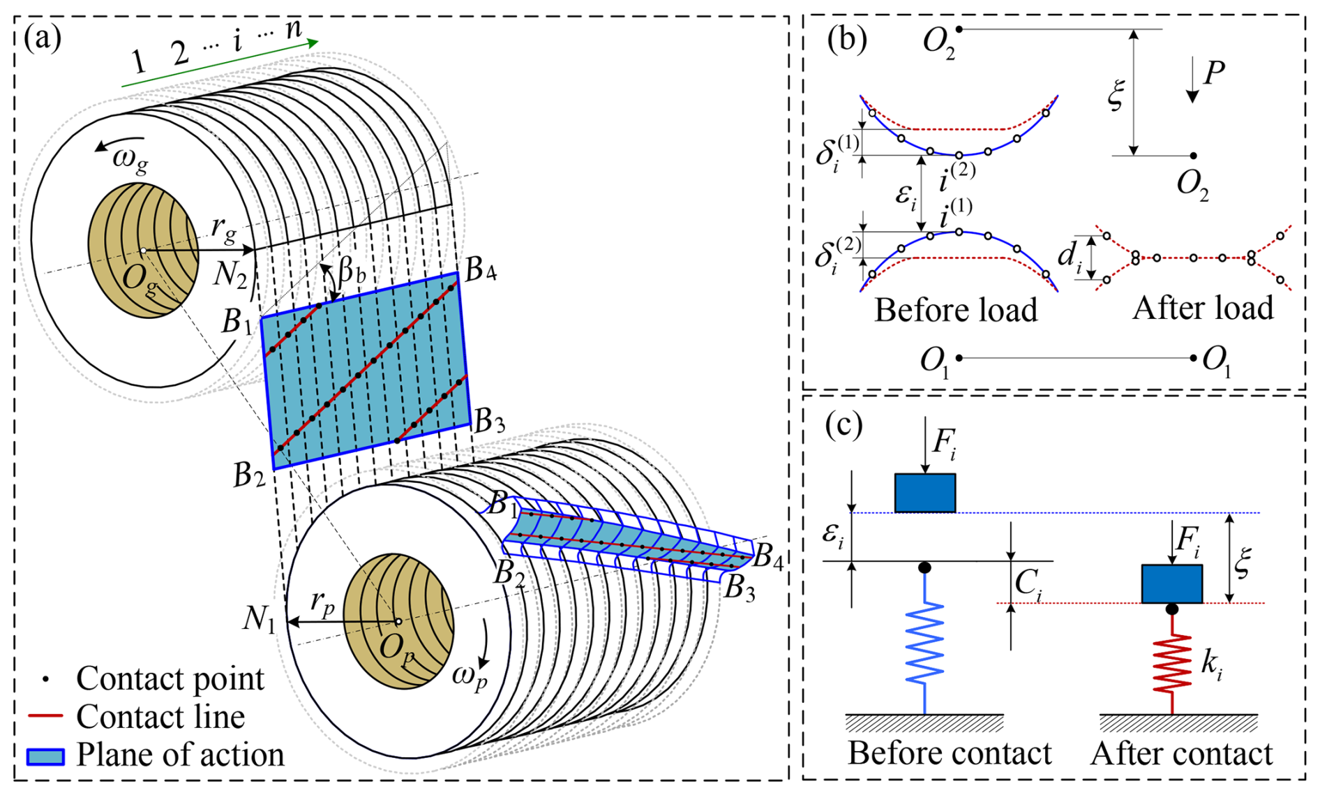
The continuous dynamic mesh process of a gear pair within one mesh cycle can be discretized into a series of engagement positions. The contact lines and contact points in one engagement position can be arranged on the sliced plane of action, as shown in Fig. 1a. The positional relationship of the contact points for a certain contact line before and after loading is shown in Fig. 1b, and the positional relationship of a single contact point pair before and after loading is shown in Fig. 1c. The deformation compatibility relationship in one engagement position can be written as
where λG is the global flexibility matrix of the tooth surface, which can be determined using the potential energy and slice method (Sainsot And et al., 2004); uL is the nonlinear contact deformation vector, which can be calculated using the analytical contact mechanics formula (Chang et al., 2015); ε is the initial clearance vector of contact point pairs; ξ is the transmission error of gear pairs; I is a vector of n×1 with all element values equal to 1; and d is the residual clearance vector of contact point pairs after loading. The load balance condition in one engagement position can be written as
where F is the load vector of contact points, H is a vector of 1×n with all element values equal to 1, and P is the gear mesh force. The non-penetrating contact condition in one engagement position can be written as
where Fi is the load for contact point i, and di is the residual clearance of contact point i. By combining Eq. (1) with Eq. (3), the LTCA equations can be obtained, and ξ and F can be solved by constructing an iterative solving algorithm. The mesh stiffness and composite mesh error are then derived from the LTCA results, with a detailed calculation procedure provided in the previous work (Chang et al., 2015).
2.1.2 Dynamic model of helical gear pair considering tooth surface wear
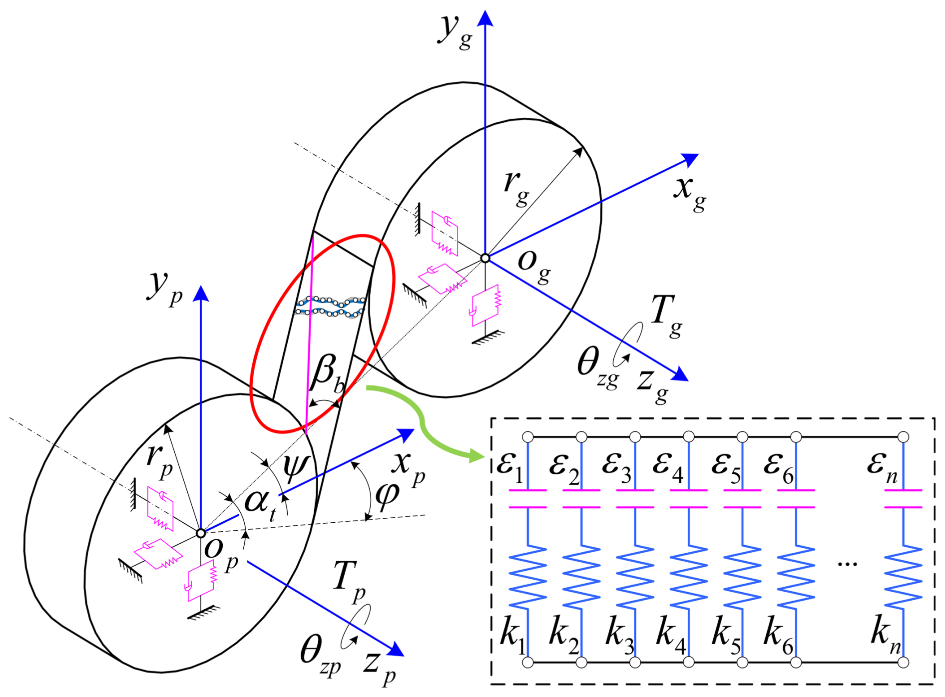
The dynamic model of a gear pair with 2 nodes and 8 degrees of freedom is shown in Fig. 2. Op and Og are the rotational center of the driving and driven gears, rp and rg are the radii of base circles for driving and driven gears, βb is the helix angle of gear pairs, αt is the transverse mesh angle of gear pairs, ψ is the installation angle, φ is the angle between the radii of the base circle and the x axis, , Tp and Tg are the input torque and output torque, ki is the contact point mesh stiffness, and εi is the contact point mesh error introduced by tooth surface wear. The generalized coordinates of gear pair nodes can be defined as
where xp, yp, zp, xg, yg, and zg are the translational displacements of the driving and driven gears along the x, y, and z axes, and θp and θg are the rotational angles of the driving and driven gears. The relative displacement of gear pairs along the normal line of action (dynamic transmission error) can be written as
where V is the projection vector of the displacements of the gear pair nodes along the normal line of action and can be written as
Considering the time-varying mesh stiffness and composite mesh error, according to Newton's second law, the motion differential equations for a gear pair considering tooth surface wear can be written as
where mi () is the mass of the pinion and wheel; Izi () is the moment of inertia around the z axis for the pinion and wheel; () are the supporting stiffnesses for the pinion and wheel; and () are the supporting damping for the pinion and wheel. By using the Newmark numerical integration method, the vibration displacement of the gear pair can be obtained, and the dynamic mesh force of the gear pair can then be solved.
2.2 Tooth surface wear depth calculation
In this section, the Archard wear formula is employed to calculate the wear depth at any contact point on the tooth surface. The calculation formula can be written as
where h is the wear depth, σH is the dynamic contact stress, s is the sliding distance, and k is the wear coefficient.
2.2.1 The relative sliding distance calculation method
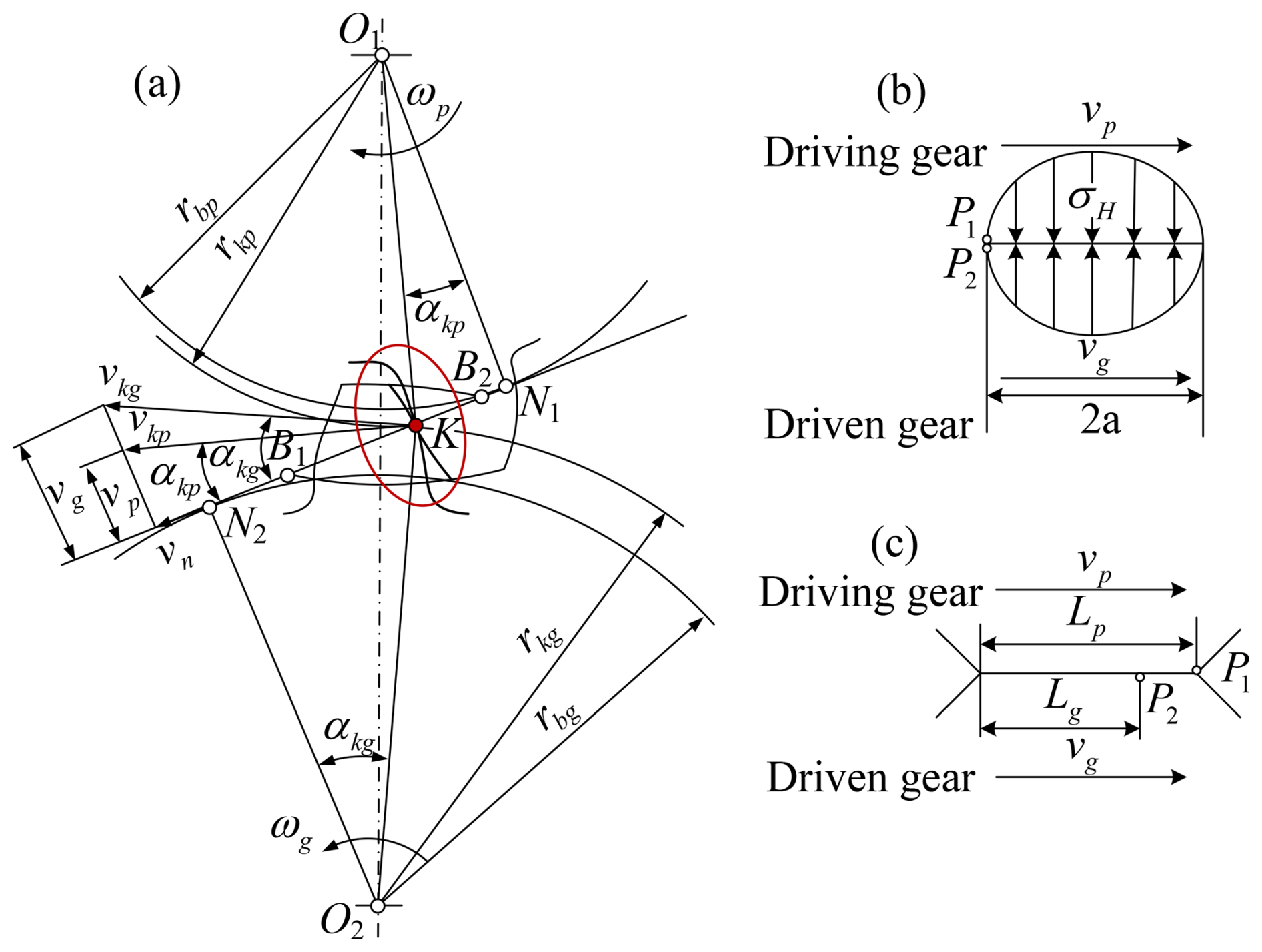
Figure 3 shows the dynamic engagement process of a gear pair from end face view. N1N2 and B1B2 are the theoretical and actual meshing lines, ωp and ωg are the angular velocities of the driving and driven gears, αkp and αkg are the pressure angles for the two gears at the meshing point K, rkp and rkg are the distances from the meshing point K to the rotation centers of the two gears, rbp and rbg are the base circles of the two gears, vkp and vkg are the linear velocities of the two gears at meshing point K, and vp and vg are the tangential velocities of the two gears at meshing point K. According to the concept of “single point observation”, the relative sliding distance between tooth surfaces can be calculated using (Flodin and Andersson, 1997)
where sp and sg are the relative sliding distances at the contact points of the driving and driven gears, respectively; a is the half width of the Hertz contact zone; and λp and λg are the relative sliding coefficients of the driving and driven gears, respectively, which can be calculated using
where Lp and Lg are the tangential displacement of the driving and driven gears at the contact point, and vp and vg are the tangential velocities of the driving and driven gears at the contact point, calculated using
where ωp and ωg are the rotational angular velocities of the driving and driven gears. Rp and Rg are the curvature radii of the driving and driven gears, respectively, which can be determined using
where ri is the distance from the contact point to the rotational center of gears, rbi is the base circle radius of gears, and ei is the wear depth at the mesh point.
2.2.2 The wear coefficient calculation method
The wear coefficient k in the Archard wear model is an empirical parameter that depends on material properties and operating conditions. In practice, tooth surface errors, vibration displacements, and time-varying meshing stiffness lead to uneven load distribution, resulting in different lubrication regimes (boundary, mixed, or EHL) at different contact points. Therefore, a dynamic wear coefficient is required for accurate wear prediction under dynamic conditions. Priest and Taylor (2000) summarized the wear coefficients of piston ring contact surfaces under different lubrication conditions, and Ding and Kahraman (2007) introduced them into the wear calculation process of gear pairs under dynamic working conditions. The dynamic wear coefficient can be calculated using (Priest and Taylor, 2000)
where λ is the film thickness ratio coefficient, and k0 is the wear coefficient under boundary lubrication. The film thickness ratio coefficient λ can be calculated using
where Rqi is the root mean square roughness, and hmin is the minimum oil film thickness between tooth profiles, which can be determined using (Dowson, 1998)
where α0 is the pressure viscosity coefficient of the lubricant, v0 is the dynamic viscosity of the lubricant, Re is the equivalent curvature radius of the friction surface at the current contact point, Ee is the equivalent elastic modulus, W is the load per unit gear width, and u is the average tangential velocity of the gear pairs (where ). The wear coefficient k0 under boundary lubrication can be determined based on Janakiraman et al. (2014).
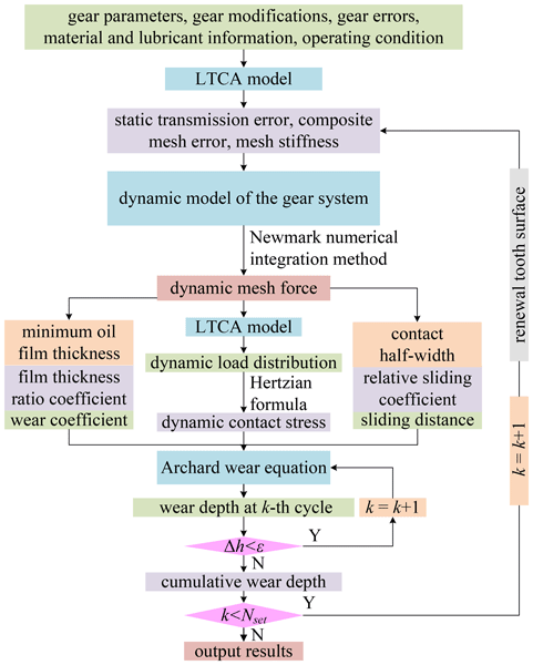
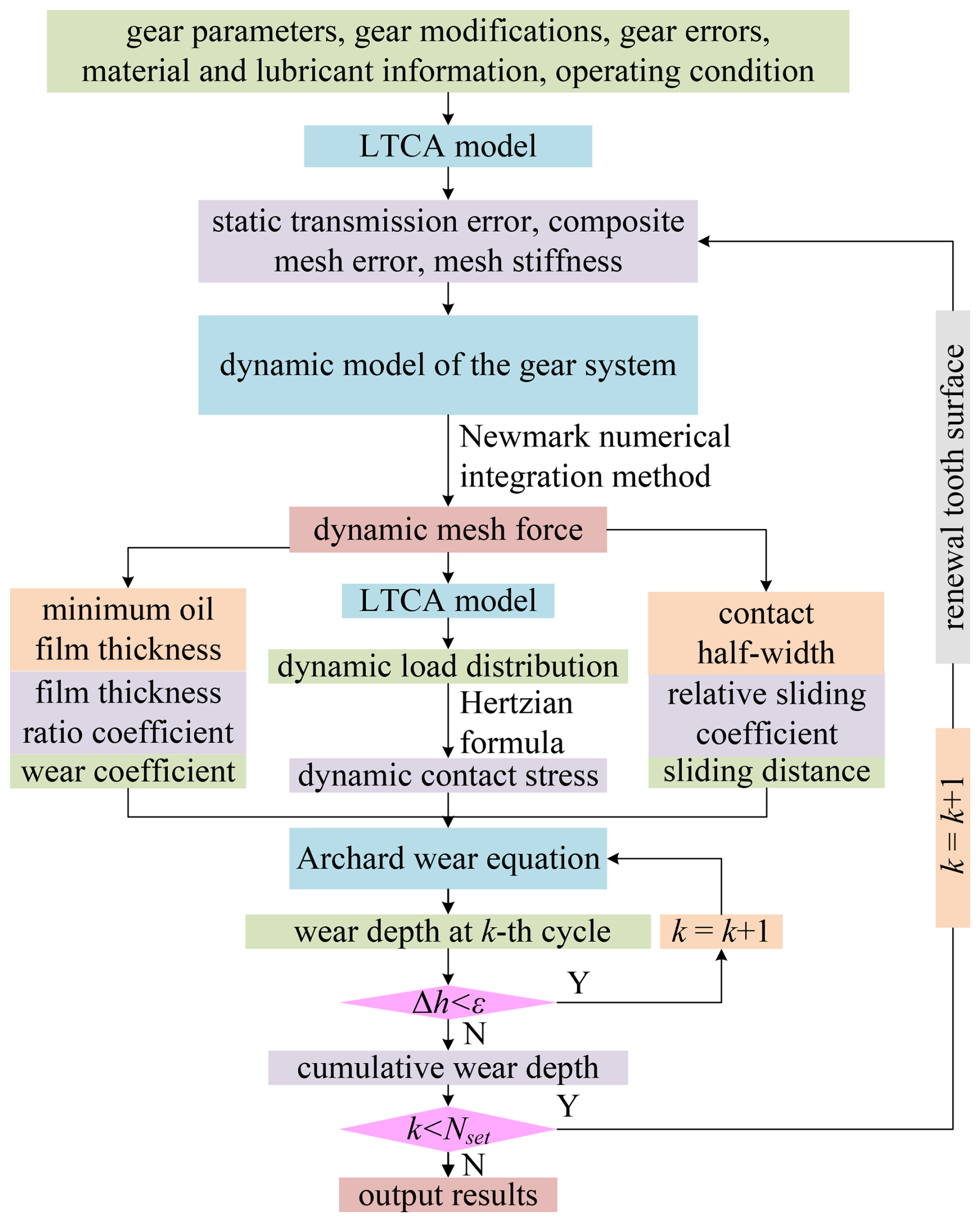
The numerical solution process for dynamic wear of the tooth surface is shown in Fig. 4. System parameters are first input into the LTCA model to obtain dynamic mesh excitations iteratively. These excitations are then introduced into the gear dynamic model to solve for dynamic mesh force using the Newmark method. The LTCA model is solved again to obtain the dynamic load distribution, from which the 3D dynamic contact stress is determined via the Hertz formula, along with relative sliding distance and wear coefficient. Finally, these quantities are fed into the Archard wear formula to obtain the wear distribution for the kth wear cycle. This loop repeats until the preset cycle Nset is reached, after which the results are output. During the solution process, the tooth surface geometry is updated whenever the wear depth reaches ε (1 µm), since micro-geometric changes significantly affect contact stress and relative sliding velocity. If the wear depth of the driving and driven gears are defined as hp and hg, Rp and Rg are the curvature radii before wear, and the mesh error introduced by gear wear is ef. The new curvature radius and mesh errors can be determined using
The proposed model is validated against the spur gear wear experiment in Flodin (2000) and the helical gear results in Flodin and Andersson (2000). The basic parameters of the gear pairs and the related lubricant properties are listed in Table 1. For spur gears, the maximum wear depth increases rapidly during the initial running-in period and then gradually stabilizes; the early deviations between predictions and experiments are attributed to the additive-free lubricant and asperity contacts, as shown in Fig. 5a. For helical gears, the predicted wear distributions on the front, middle, and rear sections of the driving gear after 10 000 revolutions differ slightly from those in Flodin and Andersson (2000) due to the use of the LTCA model and the dynamic wear coefficient instead of the Winkler model, but the overall trends are fully consistent, as illustrated in Fig. 5b–d.
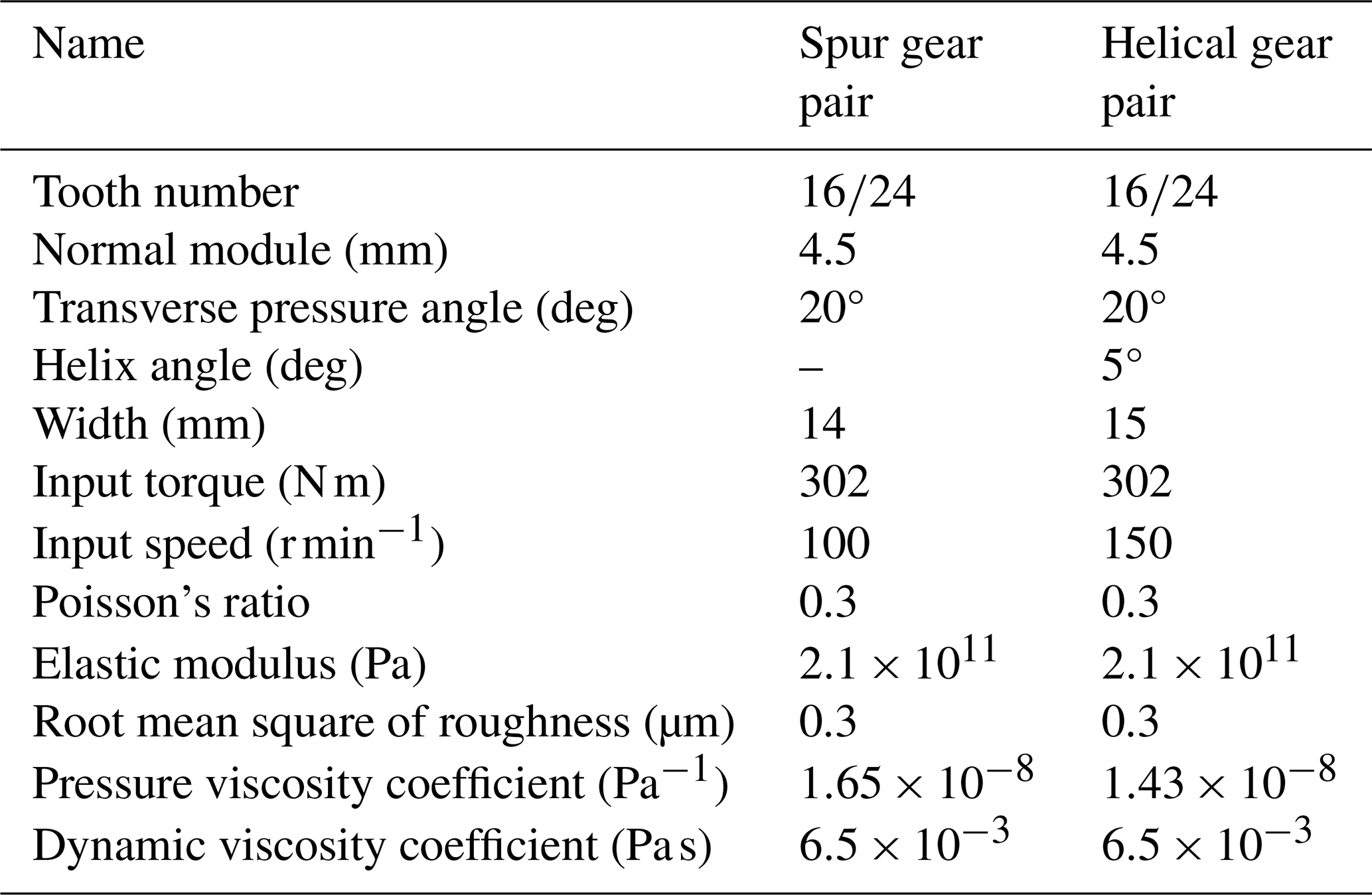
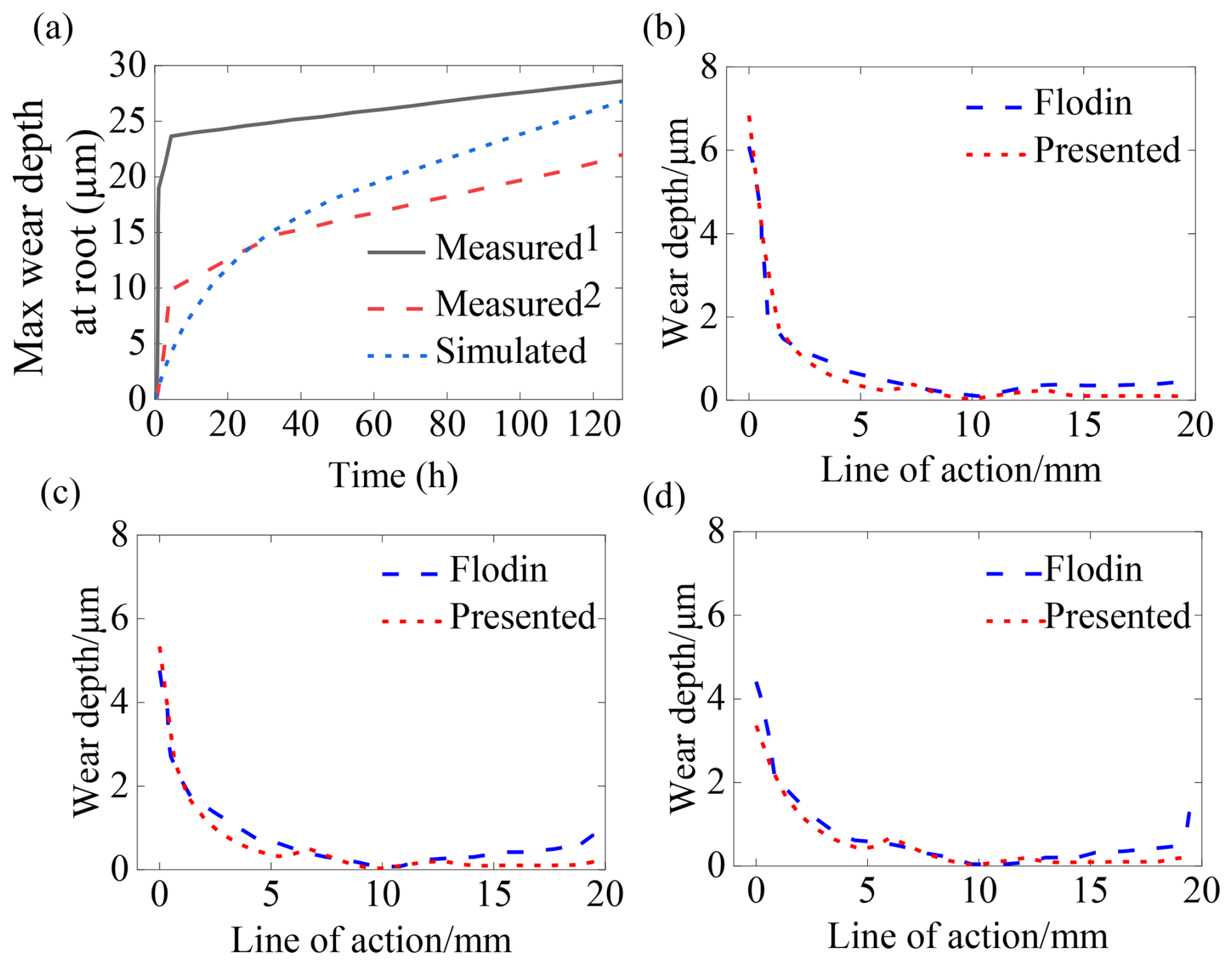
Figure 5Dynamic tooth surface wear comparison: (a) maximum wear depth comparison at the tooth root of spur gears, (b) wear depth comparison in the front section of helical gears, (c) wear depth comparison in the middle section of helical gears, and (d) wear depth comparison in the rear section of helical gears.
5.1 The effect of operating conditions
Taking a helical gear pair as an example, the contact characteristics and dynamic evolution process of tooth surface wear of various unmodified and modified helical gear pairs are investigated. The gear parameters are shown in Table 2. The pressure viscosity coefficient of lubricating oil is Pa−1, and the dynamic viscosity coefficient is Pa s. Figure 6 shows the variations in the root mean squares of the dynamic transmission errors of the helical gear pair before wear with the input speed, at an input torque of 3200 N m. It can be observed that the system exhibits significant primary and secondary harmonic resonances, while higher-order harmonic resonances are very weak. The main resonance of the system occurs around 3800 r min−1, and the second harmonic resonance occurs around 1900 r min−1.
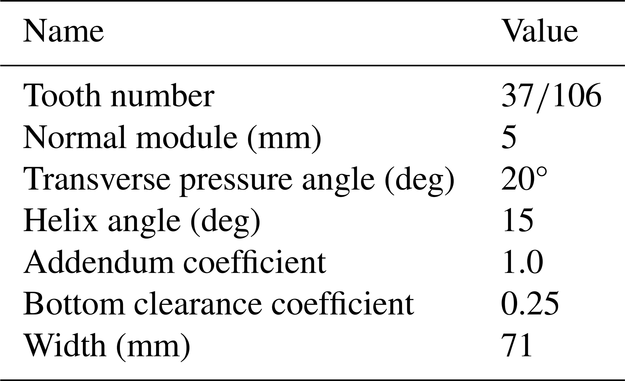
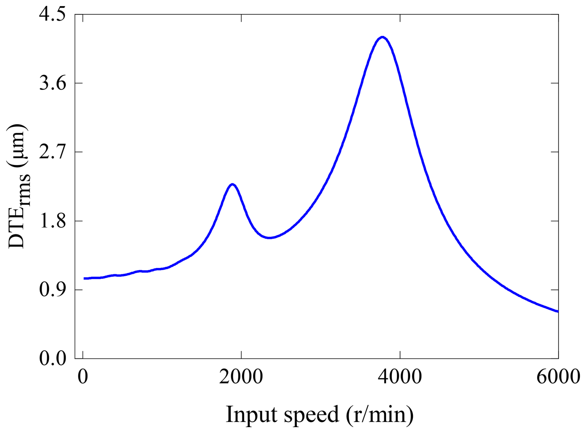
Figure 7a shows the dynamic contact stress of the unmodified gear pair before wear when the input speed is 1000 r min−1 and the input torque is 3200 N m. Due to the consideration of factors such as the uneven load distribution and the curvature radius, the dynamic wear coefficient of different contact areas on the tooth surface varies, as shown in Fig. 7d. The sliding distances of the driving and driven gears are shown in Fig. 7b and c, respectively. Figure 7e and f show the dynamic wear distributions of the helical gear pair when the driving gear rotates 1 million revolutions. Although the sliding distance between the tooth profiles reaches its maximum in the tooth root of the driving and driven gears, the tooth surface wear is affected by the combined effects of contact stress, relative sliding distance, and dynamic wear coefficient. Under this coupling effect, the tooth surface wear of the driving gear in the early wear stage is mainly concentrated near the tooth root, while the tooth surface wear of the driven gear in the early wear stage is mainly concentrated near the tooth tip. Due to the gear ratio of 37106, the tooth surface wear of the driving gear is more severe compared to the driven gear during the same wear cycle. In the subsequent results and discussions, the dynamic wear distribution is focused on the driving gear.
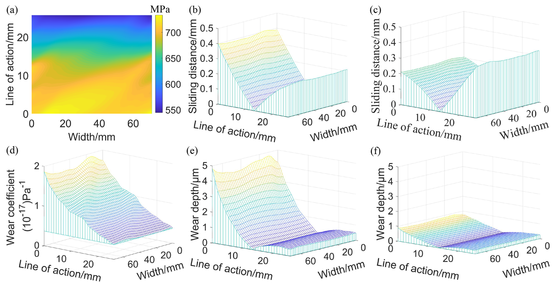
Figure 7Simulated results for helical gear pair: (a) dynamic contact stress before wear; (b, c) sliding distance of driving and driven gear, respectively; (d) dynamic wear coefficient; and (e, f) dynamic wear depth of driving and driven gear, respectively.
5.1.1 The effect of input speed
The vibration state of the gear system varies at different input speeds. The dynamic contact stress on tooth surface under different input speeds is shown in Fig. 8a–c. When the driving gear rotates 1 million revolutions, the wear depth of the tooth surface under different input speeds is given in Fig. 8d–f. It can be observed that there are significant differences in the contact stress distribution under different input speeds. Compared with the results obtained at the input speed of 1000 r min−1, the dynamic contact stress fluctuations of the tooth surface are more pronounced at input speeds of 2000 and 4000 r min−1, and the maximum contact stress gradually increases. This is because the main resonance speed of the system is around 4000 r min−1, while the secondary resonance speed is around 2000 r min−1, as shown in Fig. 6. At this time, the system has significant vibration displacement. The variation pattern of tooth surface wear distribution is similar to that of contact stress distribution, and there is a significant fluctuation in the tooth surface wear distribution when the input speed is 4000 r min−1.
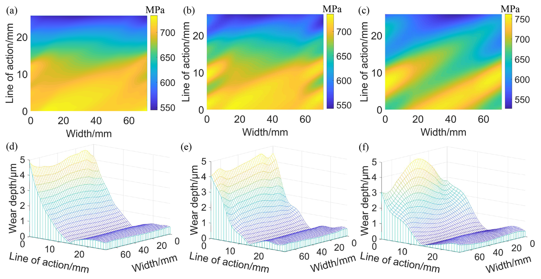
Figure 8Dynamic contact stress and wear depth of helical gear pair: (a–c) contact stress at the input speeds of 1000, 2000, and 4000 r min−1 and (d–f) wear depth at the input speeds of 1000, 2000, and 4000 r min−1.
5.1.2 The effect of input torque
The dynamic contact stress distribution of the helical gear pair under different input torques is shown in Fig. 9a–c. When the driving gear rotates 1 million revolutions, the wear depth of the tooth surface is given in Fig. 9d–f. It can be observed that due to the small changes in dynamic mesh excitations of gear pairs under different input torques, the system vibration displacement changes are also weak. Therefore, there is no significant difference in the distribution of contact stress. However, the maximum contact stress on the tooth surface gradually increases significantly. The variation pattern of tooth surface wear distribution is similar to that of contact stress distribution. The difference in tooth surface wear distribution under different input torques is slight, but the maximum wear increases significantly.
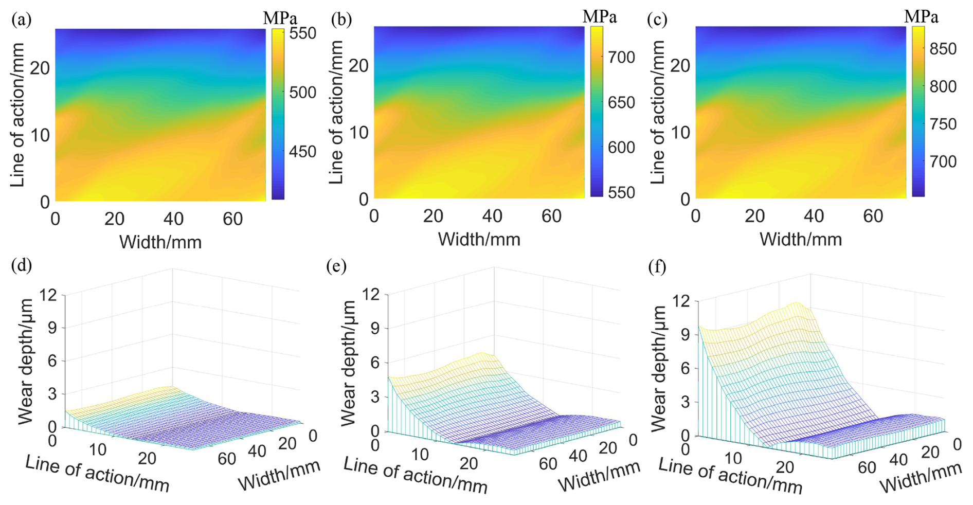
Figure 9Dynamic contact stress and wear depth of helical gear pair: (a–c) contact stress at the input torques of 1800, 3200, and 4600 N m and (d–f) wear depth at the input torques of 1800, 3200, and 4600 N m.
5.2 The effect of tooth surface modifications
5.2.1 Gear contact state and tooth surface wear
Figures 10 and 11 show the dynamic evolution process of contact stress distribution and tooth surface wear of the unmodified helical gear pair when the input torque is 3200 N m and the input speed is 1000 r min−1. The contact stress distribution of the gear pair before wear is shown in Fig. 10a. Due to the higher contact ratio of helical gear pairs, there is no significant abrupt change in the contact stress distribution. The relative sliding between tooth profiles reaches its maximum at the tooth tip and root position, while there is almost no relative sliding near the pitch line. Therefore, gear wear is mainly concentrated in the tooth tip and root, as shown in Fig. 11a. In the early stage of gear wear, the contact stress at the tooth root of the driving gear is relatively high. As the wear cycle increases, the cumulative rate of wear depth at the tooth root of the driving gear is much larger than that at the tooth tip position. There is almost no wear near the pitch line of gears, so the contact stress distribution gradually presents a “U-shaped” distribution along the tooth profile direction. A clear contact stress concentration phenomenon can be observed. Specifically, the contact stress at the tooth tip and root is relatively small, while the contact stress near the pitch line increases significantly, as shown in Fig. 11d. Under the same working condition, the dynamic evolution process of contact stress distribution and tooth surface wear of the helical gear pair with tip relief is shown in Figs. 12 and 13. Both the driving and the driven gears are subjected to tip relief; the length of tip relief is 13 mm, and the maximum amount of tip relief is 20 µm. The tip relief curve is a quadratic parabola, and specific details about tip relief are shown in our previous work (Yuan et al., 2021).
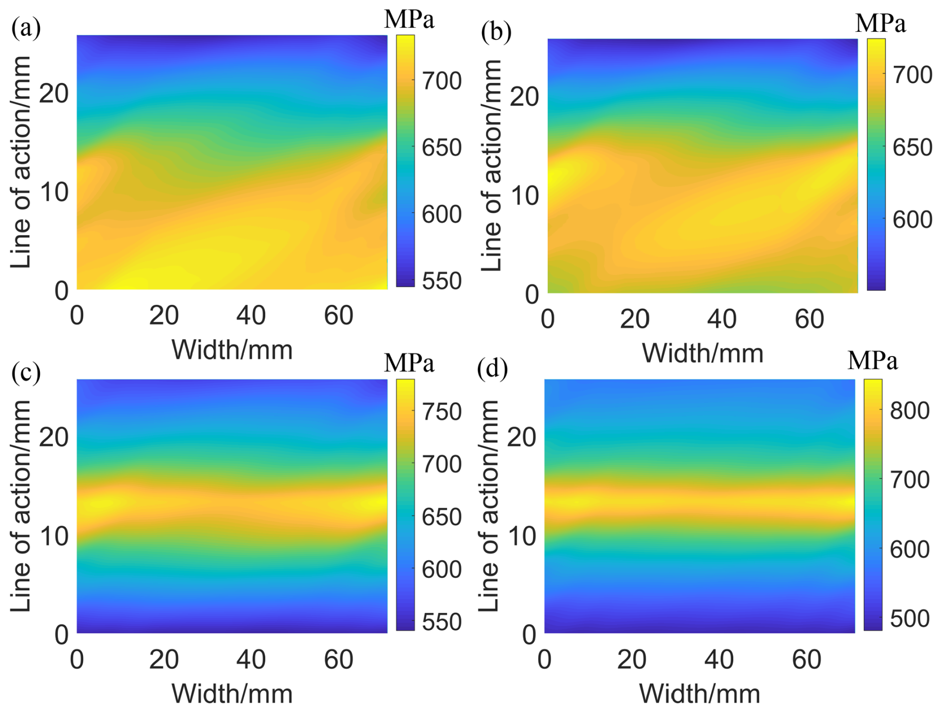
Figure 10Dynamic contact stress evolution process of unmodified helical gear pair: (a) 0 million cycles, (b) 1 million cycles, (c) 7 million cycles, and (d) 15 million cycles.
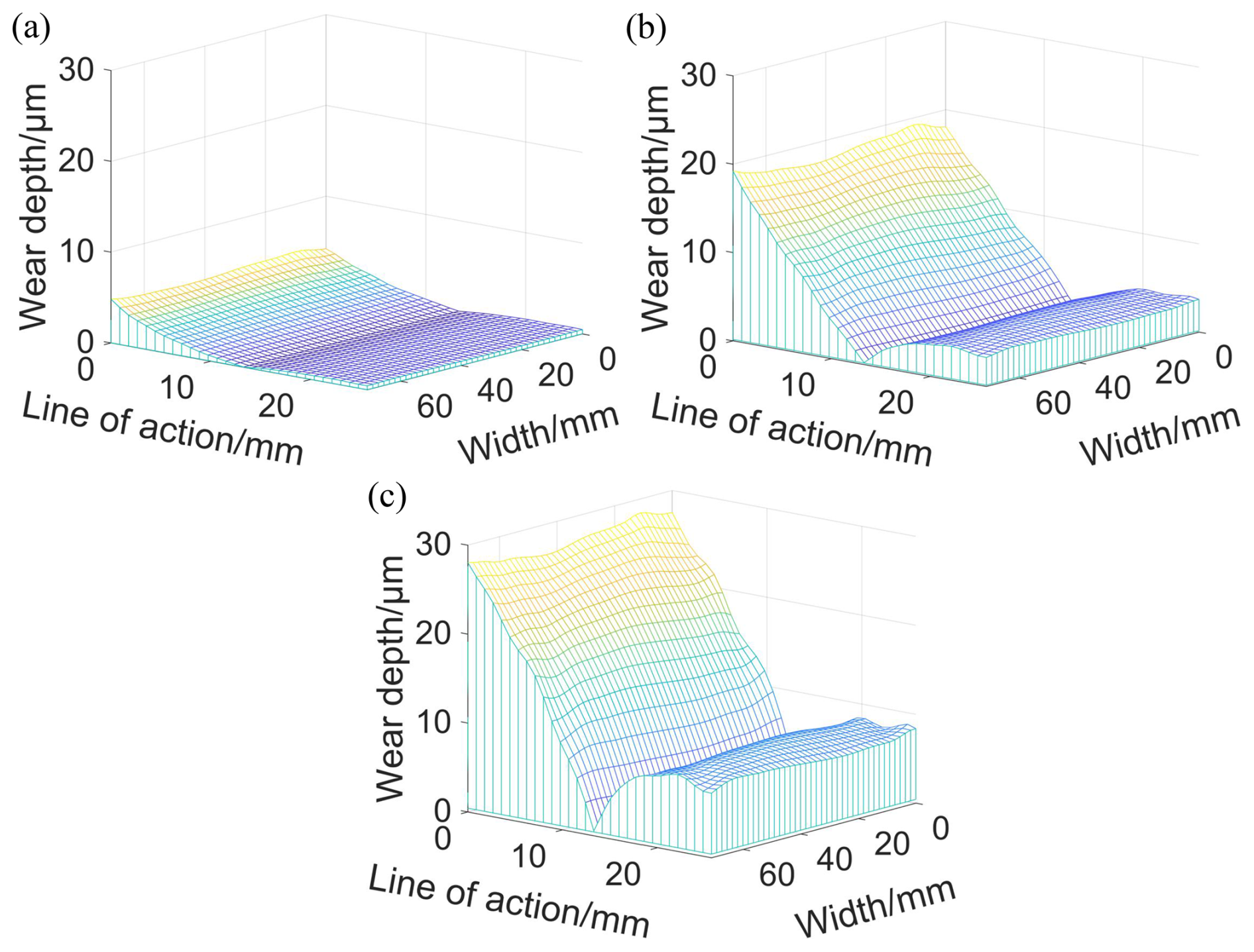
Figure 11Dynamic tooth surface wear evolution process of unmodified helical gear pair: (a) 1 million cycles, (b) 7 million cycles, and (c) 15 million cycles.
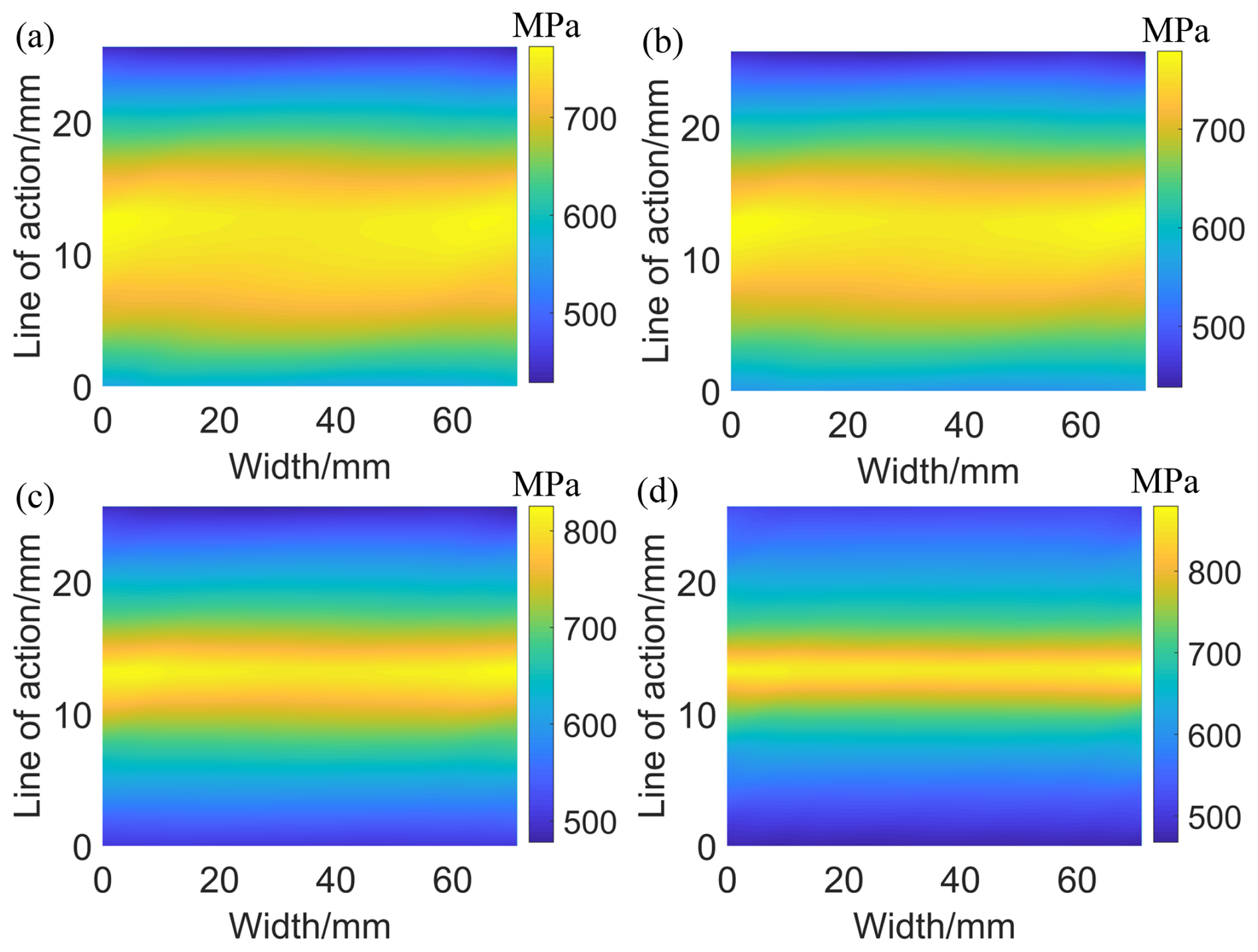
Figure 12Dynamic contact stress evolution process of helical gear pair with tip relief: (a) 0 million cycles, (b) 1 million cycles, (c) 7 million cycles, and (d) 15 million cycles.
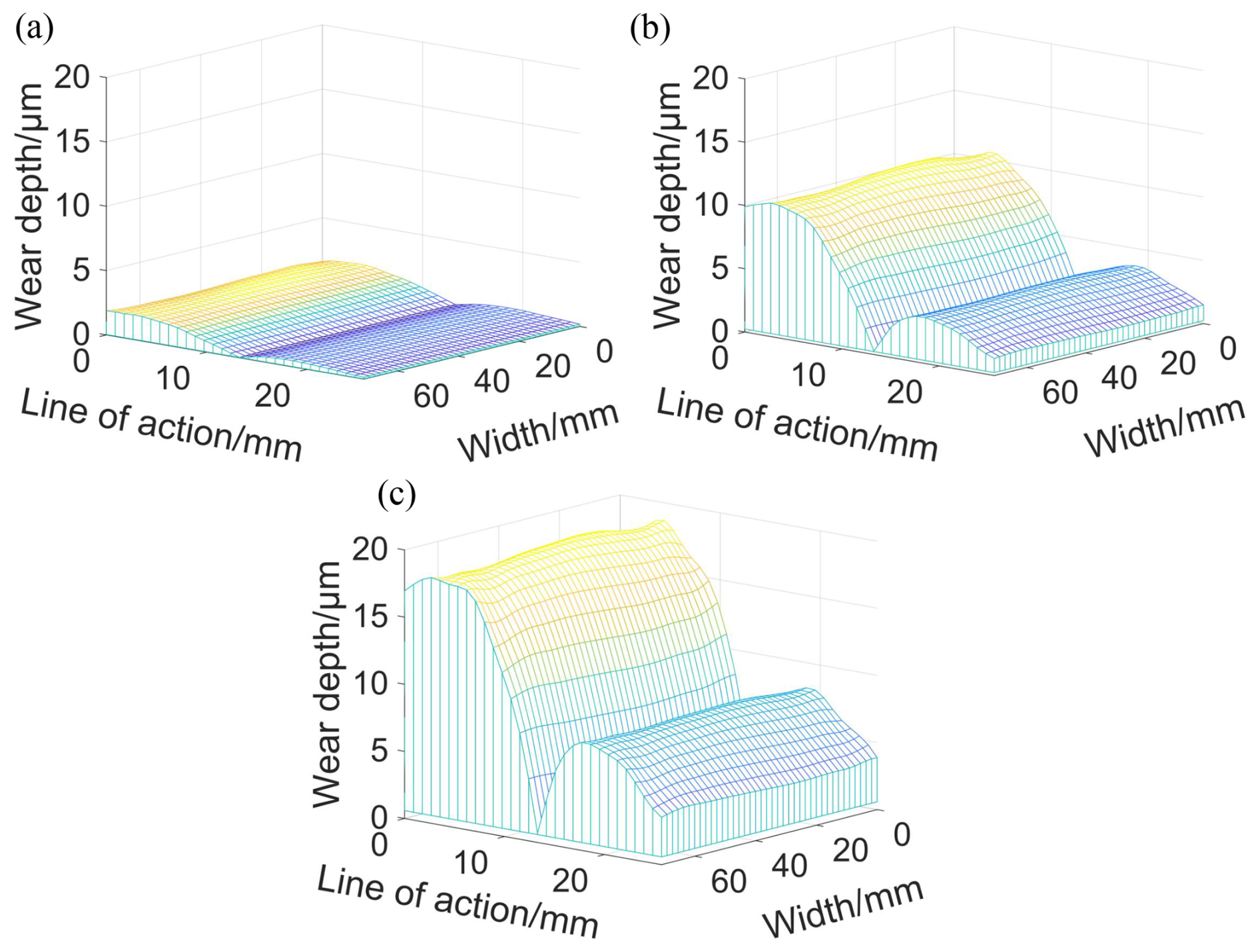
Figure 13Dynamic tooth surface wear evolution process of helical gear pair with tip relief: (a) 1 million cycles, (b) 7 million cycles, and (c) 15 million cycles.
The tip relief introduces mesh errors on the tooth surface at the tooth tip and root positions of the driving and driven gears. Therefore, when the tooth surface is not yet worn, the contact stress between the tooth tip and root positions of the modified gear pair is significantly less than that of the unmodified gear pair. The wear depth of the driving gear from the tooth root to the pitch line first increases slightly and then decreases, and the trend of the wear amount from the tooth tip to the pitch line is also the same. As the wear cycle increases, the contact stress gradually concentrates towards the pitch line position, and the contact stress along the tooth profile direction shows an overall “U-shaped” distribution. Under the same wear cycle, compared with the unmodified gear pair, the maximum wear depth of the gear pair with tip relief is significantly reduced. Under the same working condition, the dynamic evolution process of the contact stress distribution and tooth surface wear of the helical gear pair with a lead crown is shown in Figs. 14 and 15. A lead crown of 20 µm is adopted for modifying the driving gear, and the curve of the lead crown is also a quadratic parabola. A detailed introduction to this modification method can be found in the published work of Wang et al. (2021c).
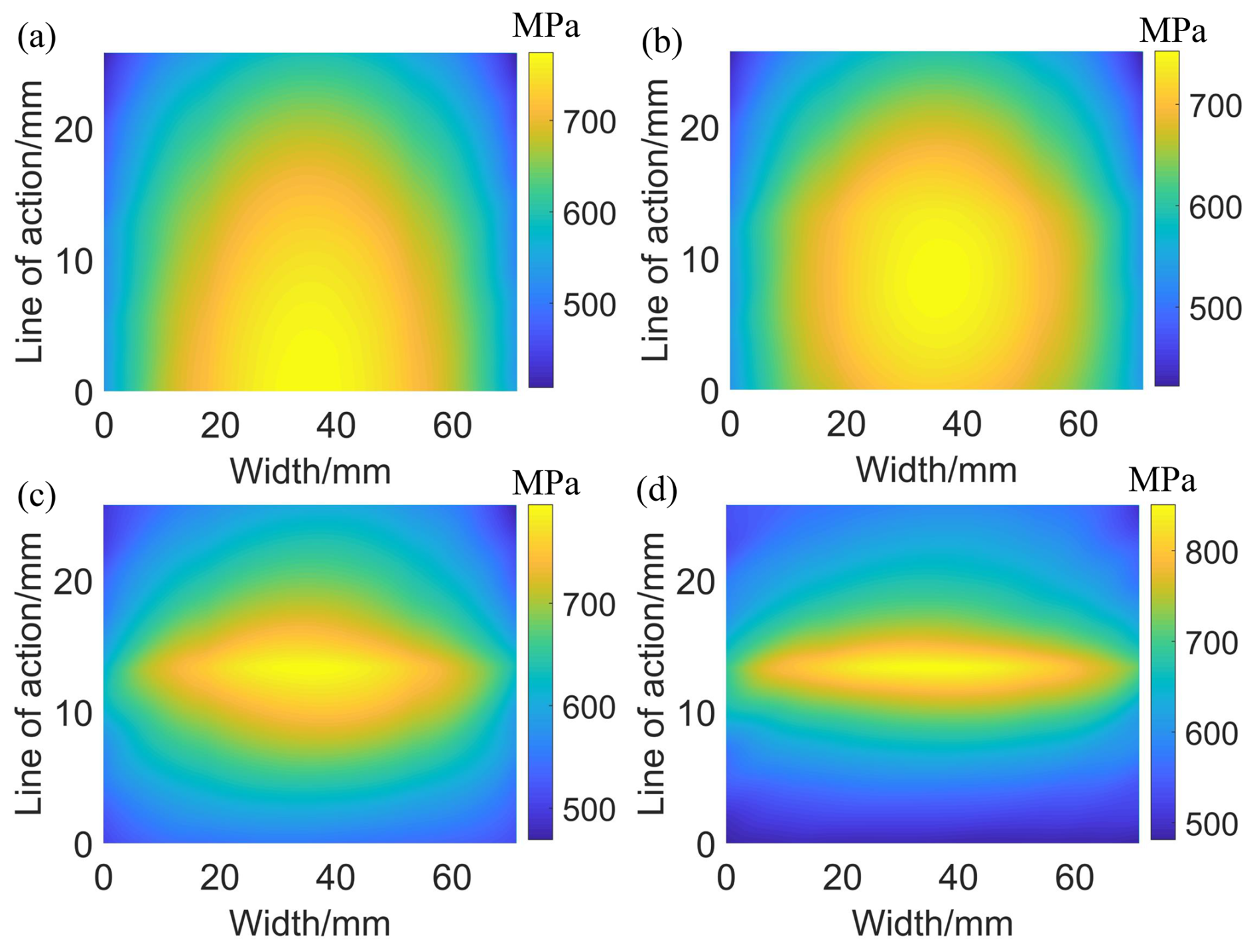
Figure 14Dynamic contact stress evolution process of helical gear pair with lead crown: (a) 0 million cycles, (b) 1 million cycles, (c) 7 million cycles, and (d) 15 million cycles.
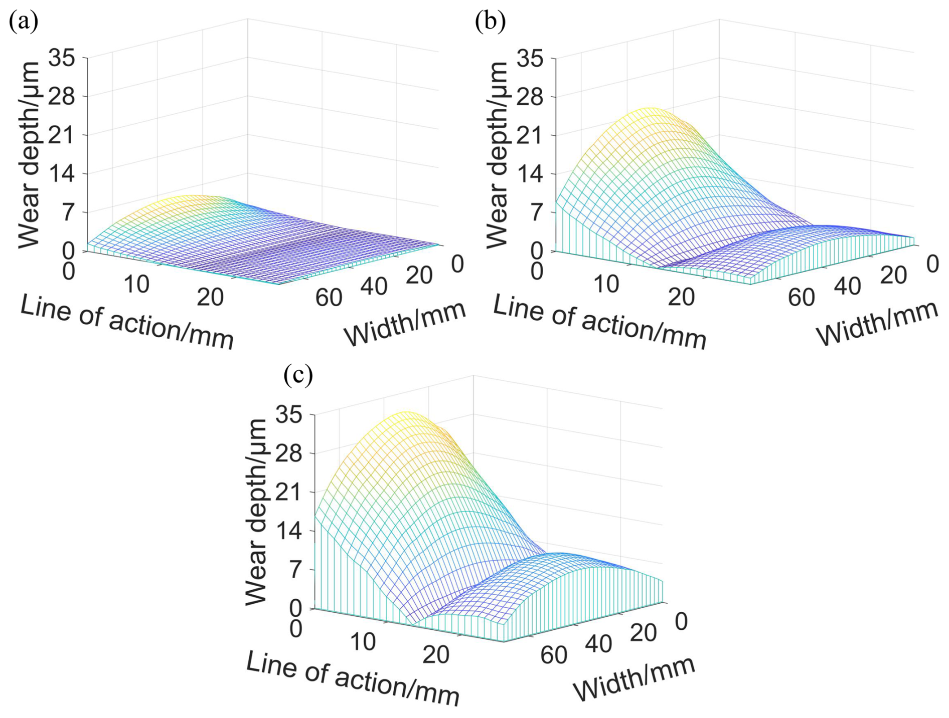
Figure 15Dynamic tooth surface wear evolution process of helical gear pair with lead crown: (a) 1 million cycles, (b) 7 million cycles, and (c) 15 million cycles.
A lead crown introduces intentional errors along the gear width. Thus, the contact stress of the gear pair with lead crown shows a trend of first increasing and then decreasing along the gear width, and the maximum contact stress occurs near the middle of the tooth root of the driving gear. The wear amount along the gear width is also larger in the middle and smaller on both sides. Due to the fact that the load distribution is concentrated towards the middle of the gear width after the lead crown, the maximum wear amount of the gear pair with the lead crown is significantly larger than that of the unmodified gear pair under the same wear cycle. As the wear cycle increases, the wear amount at the tooth tip and root gradually increases, and the contact stress gradually decreases. Thus, the contact stress gradually exhibits an elliptical distribution, and the maximum contact stress is concentrated in the center of the tooth surface.
Under the same working condition, the dynamic evolution process of the contact stress distribution and tooth surface wear of the helical gear pair with bias modification is shown in Figs. 16 and 17. A bias modification of 35 µm is employed to modify the driving gear and is performed in the three-teeth engagement zone, and the modification curve along the normal direction of the contact line is also a quadratic parabola. A detailed introduction to this method can be found in our previous work (Yuan et al., 2021).
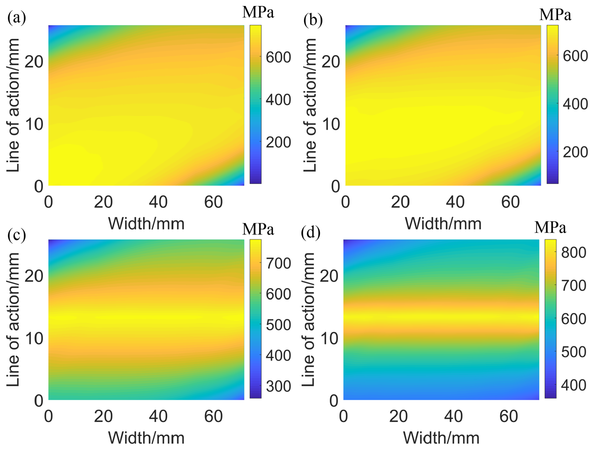
Figure 16Dynamic contact stress evolution process of helical gear pair with bias modification: (a) 0 million cycles, (b) 1 million cycles, (c) 7 million cycles, and (d) 15 million cycles.
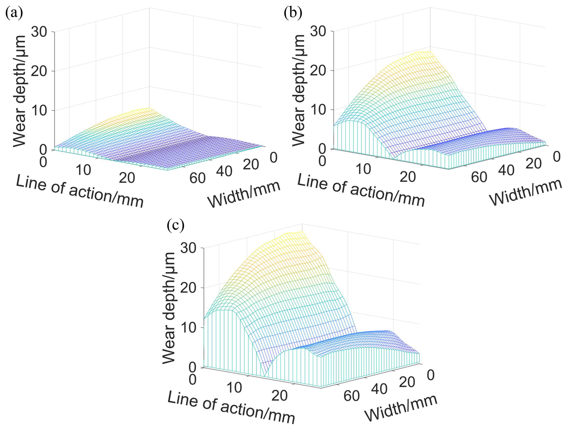
Figure 17Dynamic tooth surface wear evolution process of helical gear pair with bias modification: (a) 1 million cycles, (b) 7 million cycles, and (c) 15 million cycles.
Due to the meshing errors in mesh-in and mesh-out positions introduced by bias modification, the contact stress increases first and then decreases along the normal direction of the contact line after bias modification, indicating that the contact stress at the mesh-in and mesh-out positions is significantly less than in other areas. At the same time, the tooth surface wear at the mesh-in and mesh-out positions is also significantly smaller. The maximum contact stress is located on the left side of the tooth root of the driving gear before wear. At the tooth root of the driving gear, the contact stress gradually decreases along the gear width. The variation law of contact stress at the tooth tip along the gear width is the opposite. As the wear cycle increases, the maximum wear amount gradually increases, and a narrow area with significantly higher contact stress appears near the pitch line, while the wear amount in this area is relatively small.
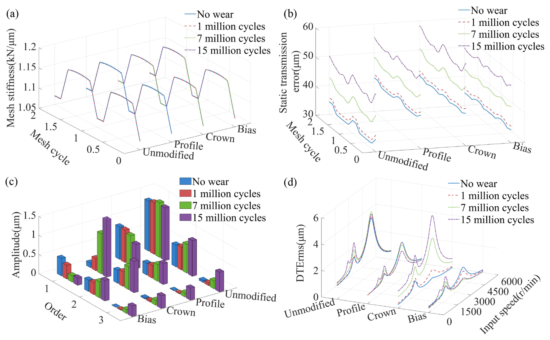
Figure 18Variations in mesh stiffness, static transmission error, and RMS of dynamic transmission error for unmodified and modified helical gear pairs after different wear cycles: (a) mesh stiffness, (b) static transmission error (time domain), (c) static transmission error (frequency domain), and (d) RMS of dynamic transmission error.
5.2.2 Mesh excitations and dynamic responses
The mesh stiffness curves are shown in Fig. 18a, the time-domain and frequency-domain results of the static transmission error of unmodified and modified helical gear pairs under different wear cycles are shown in Fig. 18b and c, and the variation law of the root mean squares of dynamic transmission errors with the input speed is shown in Fig. 18d, all at an input torque of 3200 N m and input speed of 1000 r min−1. It can be observed that the time-varying mesh stiffness curves of the unmodified and modified gear pairs remain basically unchanged before and after wear. This is because the load distributions of gear pairs with various tooth surface modifications under different wear cycles reach the full tooth surface, and the partial contact loss phenomenon that reduces the mesh stiffness value does not occur. For the unmodified helical gear pair, the fluctuation in static transmission error gradually increases as the wear cycle increases. Thus, under lower-input-speed conditions, the root mean square of dynamic transmission errors gradually increases. In addition, as the wear cycle increases, the amplitude of the first harmonic of the static transmission error first increases and then decreases, while the amplitudes of the second and third harmonics gradually increase. Therefore, the main resonance of the system first increases and then decreases, while the second and third harmonic resonances gradually increase.
For the helical gear pair with tip relief, the change in static transmission error fluctuation before and after wear is relatively small. Therefore, when the input speed is low, the root mean squares of the dynamic transmission error under different wear cycles do not change much. However, as the wear period increases, the first harmonic amplitude of the static transmission error of the gear pair gradually decreases, and the second and third harmonic amplitudes gradually increase. Therefore, as the wear period increases, the main resonance amplitude of the system gradually decreases, and the second and third harmonic resonance amplitudes increase significantly.
For the helical gear pair with lead crown, the fluctuation in the static transmission error of the gear pair gradually increases as the wear cycle increases. Therefore, when the input speed is low, the system vibration gradually increases with the increase in wear cycle. However, as the wear period increases, the amplitudes of the first, second, and third harmonics of the static transmission error gradually increase. Therefore, as the wear cycle increases, the amplitudes of the main resonance and second and third harmonic resonances of the system all increase significantly.
For the helical gear pair with bias modification, the fluctuation in static transmission error first decreases and then increases as the wear cycle increases. Therefore, in the lower-input-speed conditions, the root mean square values of the dynamic transmission error first decreases and then increases. However, as the wear cycle increases, the first harmonic amplitude of the static transmission error first decreases and then increases, and the second harmonic amplitude gradually increases. Therefore, the main resonance peak of the system near an input speed of 3800 r min−1 first decreases and then increases, while the second harmonic resonance amplitude near an input speed of 1900 r min−1 gradually increases.
A dynamic wear prediction model for helical gear pairs with various tooth surface modifications is established by integrating the Archard wear model (in which the wear coefficient is dynamically correlated with real-time contact stress), the LTCA model, and gear dynamics and is verified by comparison with published numerical results. The main findings are as follows:
-
Tooth surface wear has a negligible effect on mesh stiffness for both unmodified and modified gears but leads to distinct wear distribution patterns and load redistribution, with maximum contact stress concentrating near the pitch line as wear cycles increase.
-
The evolution of vibration response depends on modification type: for unmodified and lead crown gears, both primary and harmonic resonance peaks rise with wear, more significantly for the lead crown; for tip relief and bias modification, primary resonance is weakened, while harmonic resonance is enhanced.
-
The model is applicable to various involute cylindrical gears with errors/modifications and can be extended to thin-rimmed gears in aviation. It offers a unified framework for wear prediction, lubricant optimization, and vibration control.
The data analyzed during the current study are available from the corresponding author upon reasonable request.
Bing Yuan: writing – review and editing, funding acquisition. Yuzheng Tan: writing – original draft. Songtao Zhao: project administration. Jingyi Gong: validation, conceptualization. Hao Dong: funding acquisition.
The contact author has declared that none of the authors has any competing interests.
Publisher's note: Copernicus Publications remains neutral with regard to jurisdictional claims made in the text, published maps, institutional affiliations, or any other geographical representation in this paper. The authors bear the ultimate responsibility for providing appropriate place names. Views expressed in the text are those of the authors and do not necessarily reflect the views of the publisher.
The authors gratefully acknowledge financial support from the National Natural Science Foundation of China (grant nos. 52375062 and 52005382) and the Natural Science Basic Research Program of Shaanxi (grant nos. 2025JC-YBMS-399 and 2025JC-YBQN-651).
This research has been supported by the National Natural Science Foundation of China (grant nos. 52375062 and 52005382) and the Natural Science Basic Research Program of Shaanxi Province (grant nos. 2025JC-YBMS-399 and 2025JC-YBQN-651).
This paper was edited by Pengyuan Zhao and reviewed by Jianjun Yang and one anonymous referee.
Bajpai, P., Kahraman, A., and Anderson, N.: A surface wear prediction methodology for parallel-axis gear pairs, J. Tribol.-T. ASME, 126, 597–605, https://doi.org/10.1115/1.1691433, 2004. a
Chang, L., Liu, G., and Wu, L.: A robust model for determining the mesh stiffness of cylindrical gears, Mech. Mach. Theory, 87, 93–114, https://doi.org/10.1016/j.mechmachtheory.2014.11.019, 2015. a, b
Ding, H. and Kahraman, A.: Interactions between nonlinear spur gear dynamics and surface wear, J. Sound Vib., 307, 662–679, https://doi.org/10.1016/j.jsv.2007.06.030, 2007. a
Dong, N., Tong, R., Zhang, C., Li, S., Li, Y., and Wan, S.: An improved model of dynamic wear prediction for solid-lubricated planetary gear sets considering thermal effects, Wear, 584–585, 206415, https://doi.org/10.1016/j.wear.2025.206415, 2026. a
Dowson, D.: Modelling of elastohydrodynamic lubrication of real solids by real lubricants, Meccanica, 33, 47–58, https://doi.org/10.1023/A:1004265832496, 1998. a
Flodin, A.: Wear investigation of spur gear teeth, Tribotest, 7, 45–60, https://doi.org/10.1002/tt.3020070106, 2000. a, b
Flodin, A. and Andersson, S.: A simplified model for wear prediction in helical gears, Wear, 249, 285–292, https://doi.org/10.1016/S0043-1648(01)00556-7, 2001. a
Flodin, A. and Andersson, S.: Simulation of mild wear in spur gears, Wear, 207, 16–23, https://doi.org/10.1016/S0043-1648(96)07467-4, 1997. a, b
Flodin, A. and Andersson, S.: Simulation of mild wear in helical gears, Wear, 241, 123–128, https://doi.org/10.1016/S0043-1648(00)00384-7, 2000. a, b, c
Janakiraman, V., Li, S., and Kahraman, A.: An investigation of the impacts of contact parameters on wear coefficient, J. Tribol.-T. ASME, 136, 031602, https://doi.org/10.1115/1.4027440, 2014. a
Li, Z., Chen, Z., Guo, L., and Zhai, W.: Nonlinear dynamics of gear transmission with an improved wear model, Int. J. Mech. Sci., 299, 110399, https://doi.org/10.1016/j.ijmecsci.2025.110399, 2025a. a
Li, Z., Xiao, H., Tang, Y., Liang, G., Wang, L., and Yang, J.: A deterministic model of surface profile degradation for evaluating time-varying mesh stiffness and dynamic responses of spur gear considering tooth surface wear evolution, Mech. Syst. Signal Pr., 225, 112313, https://doi.org/10.1016/j.ymssp.2025.112313, 2025b. a
Priest, M. and Taylor, C. M.: Automobile engine tribology – approaching the surface, Wear, 241, 193–203, https://doi.org/10.1016/S0043-1648(00)00375-6, 2000. a, b
Sainsot, P., Velex, P., and Duverger, O.: Contribution of gear body to tooth deflections – a new bidimensional analytical formula, J. Mech. Design, 126, 748–752, https://doi.org/10.1115/1.1758252, 2004. a
Sánchez, M. B., Pleguezuelos, M., and Pedrero, J. I.: Influence of profile modification on the transmission error of spur gears under surface wear, Mech. Mach. Theory, 191, 105473, https://doi.org/10.1016/j.mechmachtheory.2023.105473, 2024. a
Wang, H., Tang, L., Zhou, C., and Shi, Z.: Wear life prediction method of crowned double helical gear drive in point contact mixed elastohydrodynamic lubrication, Wear, 484, 204041, https://doi.org/10.1016/j.wear.2021.204041, 2021a. a
Wang, H., Zhou, C., Wang, H., Hu, B., and Liu, Z.: A novel contact model for rough surfaces using piecewise linear interpolation and its application in gear wear, Wear, 476, 203685, https://doi.org/10.1016/j.wear.2021.203685, 2021b. a
Wang, Q., Xu, K., Huai, T., Ma, H., and Wang, K.: A mesh stiffness method using slice coupling for spur gear pairs with misalignment and lead crown relief, Appl. Math. Model., 90, 845–861, https://doi.org/10.1016/j.apm.2020.08.046, 2021c. a
Xiong, Q., Liu, X., Liu, Y., Wang, J., and Zhang, J.: Interaction between gear wear and dynamic behavior considering interface characteristics, Tribol. Int., 111013, https://doi.org/10.1016/j.triboint.2025.111013, 2025. a
Yuan, B., Liu, G., Yue, Y., Liu, L., and Shen, Y.: A novel tooth surface modification methodology for wide-faced double-helical gear pairs, Mech. Mach. Theory, 160, 104299, https://doi.org/10.1016/j.mechmachtheory.2021.104299, 2021. a, b
Zeng, L., Deng, X., Li, F., Dong, C., Wang, S., Yang, H., Tang, C., and Li, Y.: Study on dynamic wear evolution of modified gear rack considering the real-time variation of contact characteristics, Wear, 571, 205845, https://doi.org/10.1016/j.wear.2025.205845, 2025. a
Zhang, J., Zhou, J., Wu, A., Cui, Q., and Dong, N.: Lifecycle wear prediction of spur gears with time-dependent Archard model and surface topography evolution, Results in Engineering, 108495, https://doi.org/10.1016/j.rineng.2025.108495, 2025. a
Zhao, J., Sheng, W., Li, Z., Zhang, H., and Zhu, R.: Effect of lubricant selection on the wear characteristics of spur gear under oil-air mixed lubrication, Tribol. Int., 167, 107382, https://doi.org/10.1016/j.triboint.2021.107382, 2022. a
- Abstract
- Introduction
- Dynamic tooth surface wear model for helical gear pairs
- Numerical solution process for dynamic tooth surface wear
- Model comparison and validation
- Results and discussions
- Conclusions
- Data availability
- Author contributions
- Competing interests
- Disclaimer
- Acknowledgements
- Financial support
- Review statement
- References
- Abstract
- Introduction
- Dynamic tooth surface wear model for helical gear pairs
- Numerical solution process for dynamic tooth surface wear
- Model comparison and validation
- Results and discussions
- Conclusions
- Data availability
- Author contributions
- Competing interests
- Disclaimer
- Acknowledgements
- Financial support
- Review statement
- References