the Creative Commons Attribution 4.0 License.
the Creative Commons Attribution 4.0 License.
 | 04 Feb 2026
Torque modeling of a novel magnetic coupler with multi-disk flux regulation via angular displacement: analytical FEM co-design
Shaoqing Zheng
Chaojun Yang
Zhenyao Tang
Baiqing Liu
This paper proposes a novel axially fixed multi-disk magnetic flux-regulatable magnetic coupler with modular topology, which addresses critical limitations such as the structural scalability of conventional magnetic couplers. The innovation integrates three key advancements: (1) a stationary axial architecture that eliminates limitations to torque capacity expansion through concentric modular disk stacking, (2) a flux-regulation mechanism enabled by tunable magnetic reluctance paths by rotational alignment featuring through-hole high-permeability regulator disks and (3) a hybrid analytical finite element method (FEM) framework incorporating three-dimensional edge magnetic effects and eddy-current-induced counter fields. An equivalent magnetic circuit model with variable reluctance components is developed to quantify flux modulation, enhanced by Russell–Norsworthy correction factors for edge field quantification. The derived torque equations explicitly resolve skin depth dynamics and transient eddy current distributions through correction terms, and these equations are further amended based on finite element. Comprehensive three-dimensional finite element analysis validates the model's accuracy while optimizing critical parameters: the relative permeability of the magnetic flux regulator disk (MFRD) (optimal μrs=7000), regulator thickness (0.8 mm) and speed differential threshold (70 rpm peak torque). Simulation results demonstrate 0–418 N m continuous torque regulation within the range of 7–15° angular displacement. The modular design achieves torque capacity improvement over conventional axial displacement couplers through scalable disk-group multiplication. This co-design methodology establishes a foundation for high-torque magnetic transmission systems in space-constrained industrial applications, providing significant reference for detailed design and also prototype manufacturing in next steps.
- Article
(9527 KB) - Full-text XML
- BibTeX
- EndNote


Magnetic couplers represent a class of contactless electromechanical transmission devices that utilize magnetic field interactions for torque/speed transmission (Lubin et al., 2012a). The operational principle relies on modulating air-gap flux density to achieve dynamic torque regulation, offering inherent advantages including overload protection (≥ 120 % rated torque capacity) (Li et al., 2018), energy efficiency (typically 92 %–96 % transmission efficiency) and reduced mechanical wear (Aberoomand et al., 2019). These distinctive characteristics have driven their widespread adoption in petrochemical processing, thermal power generation (Kong et al., 2023) and marine propulsion systems (Jin et al., 2020).
Recent advancements in permanent magnet materials (e.g., NdFeB with Br ≥ 1.4 T) and topology optimization techniques have facilitated the emergence of novel coupler configurations (Ahmadi et al., 2024). However, existing torque characterization methodologies face critical limitations: numerical approaches like finite element analysis (FEA) demonstrate constrained parametric flexibility (Meng et al., 2015), while conventional analytical models (e.g., the layer model method) require oversimplified boundary conditions that compromise accuracy (typical error margin 8 %–15 %) (Lubin et al., 2012b). Meshless methods offer advantages such as avoiding mesh distortion, naturally handling moving boundaries and strong fringing effects, and are suitable for contactless coupling problems. However, these methods also exhibit certain limitations: high computational costs and complexity in addressing material non-linearities (Wang et al., 2014). This dichotomy underscores the need for enhanced modeling frameworks that balance computational efficiency and predictive accuracy during preliminary design phases (Wang and Zhu, 2018).
Current magnetic coupler architectures – including cylindrical, dual-disk and conical variants – predominantly employ axial displacement mechanisms for air-gap adjustment (Du et al., 2020). Such designs necessitate complex control systems and exhibit limited scalability in torque density (Lz et al., 2022). As industrial demands escalate for compact high-torque solutions, developing simplified structural configurations with enhanced torque scalability becomes imperative (Yang et al., 2020).
This study introduces a magnetic flux-regulatable magnetic coupler featuring three key innovations: (1) a stationary axial architecture eliminating limitations to torque capacity expansion through concentric PM/conductor disk stacking, (2) a flux-regulatable mechanism enabled by tunable magnetic reluctance paths via rotational alignment of slotted high-permeability regulator disks and (3) a hybrid analytical finite element method (FEM) framework incorporating three-dimensional edge magnetic effects and eddy current-induced counter fields (namely building the equivalent magnetic circuit method and establishing comprehensive torque regulation equations incorporating three-dimensional edge effects and skin depth phenomena). Subsequently, equations are further amended by FEA simulation results. Subsequent FEA simulations validate the model's predictive accuracy guide parametric optimization of critical dimensions.
The paper is structured as follows: Sect. 2 details the operational principles and mathematical modeling, Sect. 3 derives comprehensive torque regulation equations and Sect. 4 presents comparative FEA results.
2.1 Core mechanism of flux-regulatable coupler
This multi-group flux-regulatable magnetic coupler employs a modular architecture comprising several identical disk groups. Each disk group consists of a permanent magnet disk (PMD) containing permanent magnets, a needle roller bearing, a magnetic flux regulator disk (MFRD) and a conductor disk (CD) containing the copper conductor. Each disk group is equipped with a speed regulation device comprising a small gear and a stepper motor. As shown in Fig. 1b, the outer edge of each magnetic flux regulator disk has gear teeth for rotational transmission. The stepper motors are fixed on the connecting piece, with small gears engaging the gear teeth on the magnetic flux regulator disk.
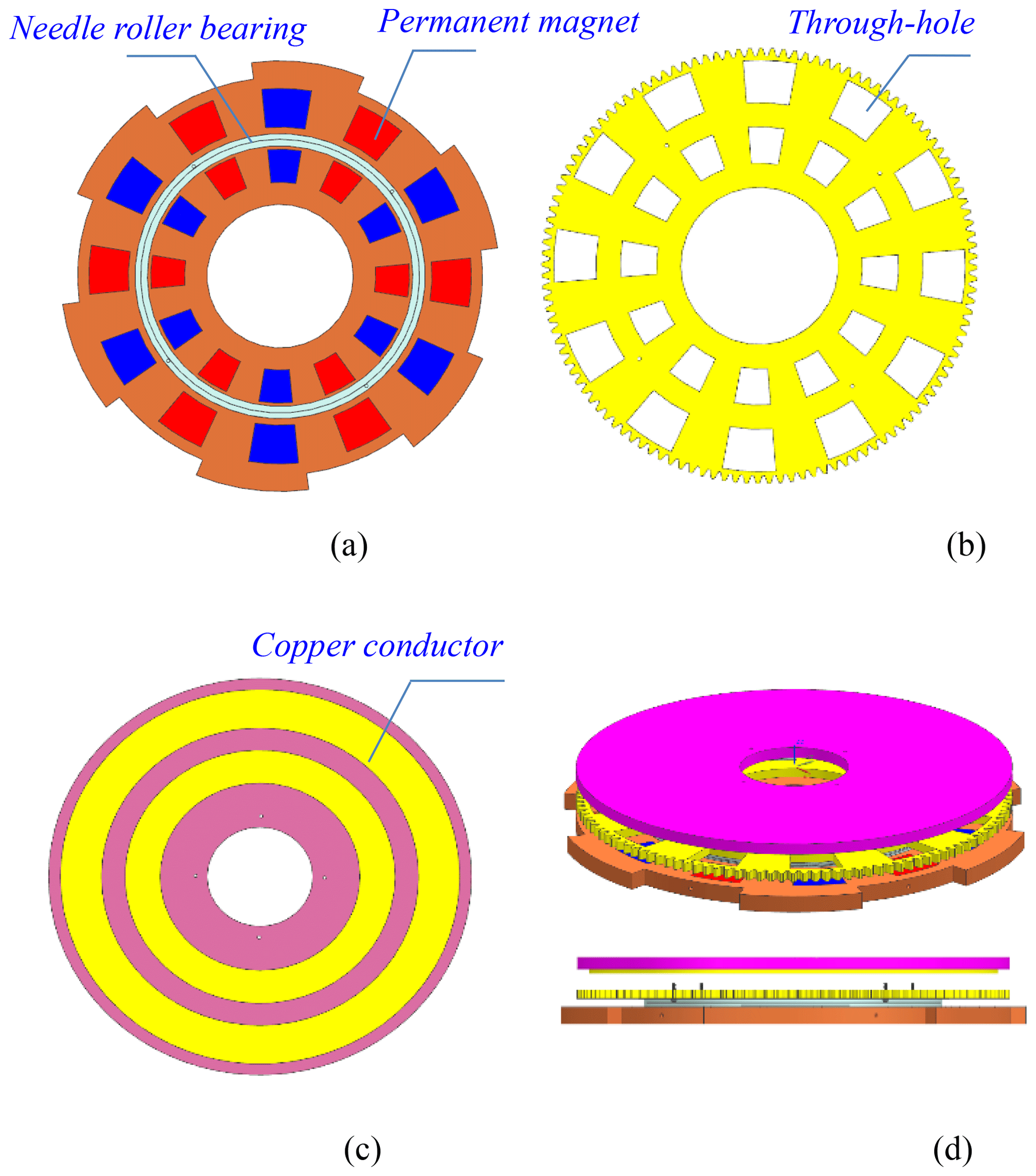
Figure 1Modular configuration of single disk group: (a) permanent magnet disk (PMD) with dual concentric PM arrays, (b) magnetic flux regulator disk (MFRD) with through-hole, (c) conductor disk (CD), (d) assemble configuration of a single disk group.
In Fig. 1a and b, permanent magnets are radially arranged in dual concentric circles on the permanent magnet disk, with alternating N–S poles set equidistantly (illustrates 12 magnets per circle and 15° angular spacing in this paper). The MFRD is made of soft magnetic material with high permeability, which features several through-holes and is identical in quantity and shape to the permanent magnets on the PMD. The PMD and MFRD are connected as a whole unit by a bearing, allowing only radial rotational motion.
In Fig. 1c and d, two copper conductor rings are mounted on the CD body. The PMD, MFRD and CD are concentrically arranged. All PMDs are bolted into a whole unit by the connecting piece, rotating synchronously with the input shaft. All CDs are fixed on the output shaft.
As illustrated in Fig. 2, the input shaft, PMDs and connecting piece are bolted together. Each PMD and MFRD assembly is fixed on the two end faces of the bearing, respectively, allowing relative rotation only. Meanwhile, two CDs are bolted on the two end faces of the shaft sleeve, and all shaft sleeves are bolted to the output shaft. Both the size of center holes of the PMD and MFRD are larger than the output shaft, with the output shaft passing through two bearings successively.
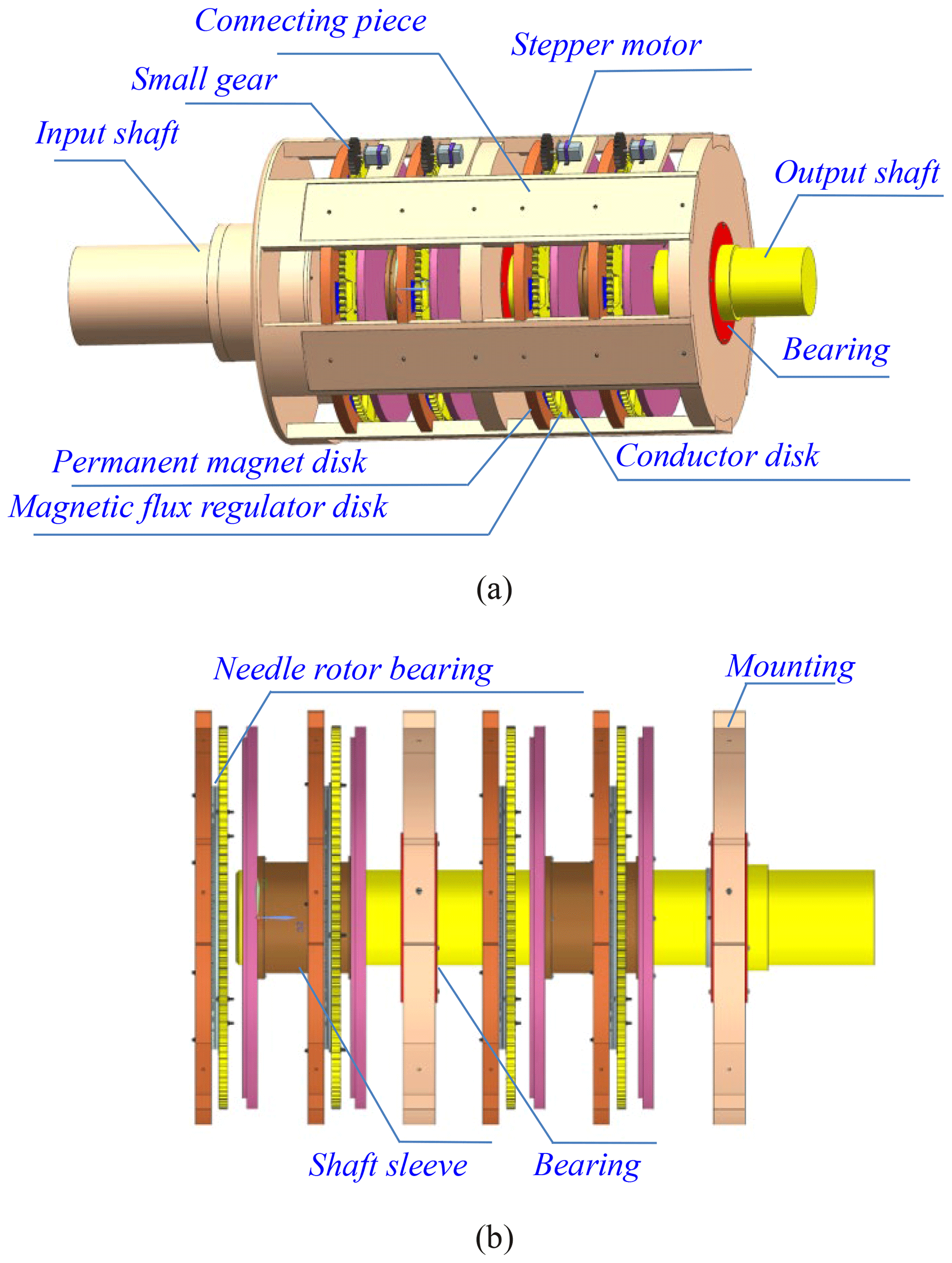
Figure 2Assembly configuration of proposed coupler: (a) full-scale 3D model with component annotation, (b) modular configuration shafting assembly drawing.
Driven by the motor, the connecting piece transmits rotational motion to the PMDs, which are mechanically coupled to the MFRDs by needle roller bearings. This synchronized rotation induces electromagnetic interaction between the PMD–MFRD assembly and the CD, thereby driving its rotation about the output shaft.
It is known that the magnetic line always closes along the path with the least reluctance according to the least reluctance low. The magnetic flux regulator disks (MFRDs) are made of soft magnetic material and have high permeability which establishes low-reluctance pathways between the PMD and CD through controlled permeability modulation.
As schematically illustrated in Fig. 3, the small gear drives the angular displacement taking place between the PMD and MFRD. When the PMD's axial polarized magnets align perpendicularly with the MFRD's through-hole, the unshielded magnet portions generate active flux channels (these portion fluxes pass through the through-hole and air gap successively, reaching CD), while remaining segments are magnetically shunted by the MFRD's permeability body.
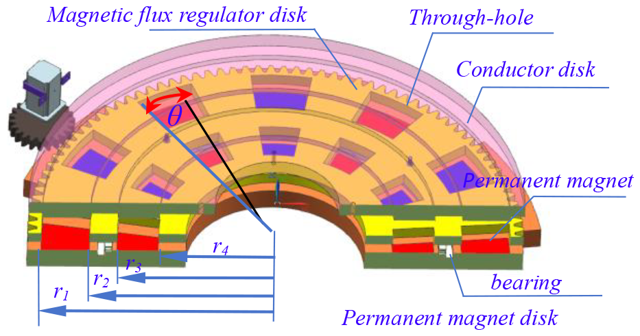
Figure 5 demonstrates the flux bifurcation mechanism: (1) the shunted flux path (black line path): originating from shielded PM segments and confined within the MFRD soft magnetic circuit, thus non-participating in electromechanical energy conversion; and (2) the active flux path (yellow line path): generated by aperture-aligned PM poles, penetrating the CD conductor domain through air-gap la1, lm and la2, thereby inducing eddy current. Consequently, the number of magnetic lines reaching the CD conductor domain can be regulated by the relative rotation angle θ between the PMD and MFRD.
Figure 3 illustrates the configuration of the disk assembly. The fan-shaped permanent magnets are concentrically arranged in two radially distributed circular arrays on the PMD, maintaining equal angular spacing between adjacent magnets. Each fan-shaped permanent magnet subtends a central angle of 15°, while the angular spacing between adjacent magnets measures 15°. This symmetrical arrangement results from the uniform distribution of 12 permanent magnets per circular array, establishing periodical angular equivalence between magnetized and non-magnetized segments.
The through-holes are geometrically congruent with the fan-shaped permanent magnets to ensure two operational states: complete exposure of permanent magnets when aligned with through-holes or full magnetic shielding by the MFRD body during disk rotation. As depicted in Fig. 3, the angular boundaries of permanent magnets (blue lines) and through-holes (black lines) are distinctly marked. When these two lines coincide (θ = 0°), null magnetic flux penetration occurs. Conversely, maximum magnetic flux attains the CD when angular displacement reaches its maximum value (when θ = 15°). This configuration establishes a periodic angular variation range of 0° ≤ θ < 15° during MFRD rotation.
Notably, the torque capacity of the proposed coupler can be enhanced by the modular disk group increasing, and there are four disk groups in the coupler illustrated. Therefore, the working flow diagram of the proposed coupler with four disk groups is shown in Fig. 4.
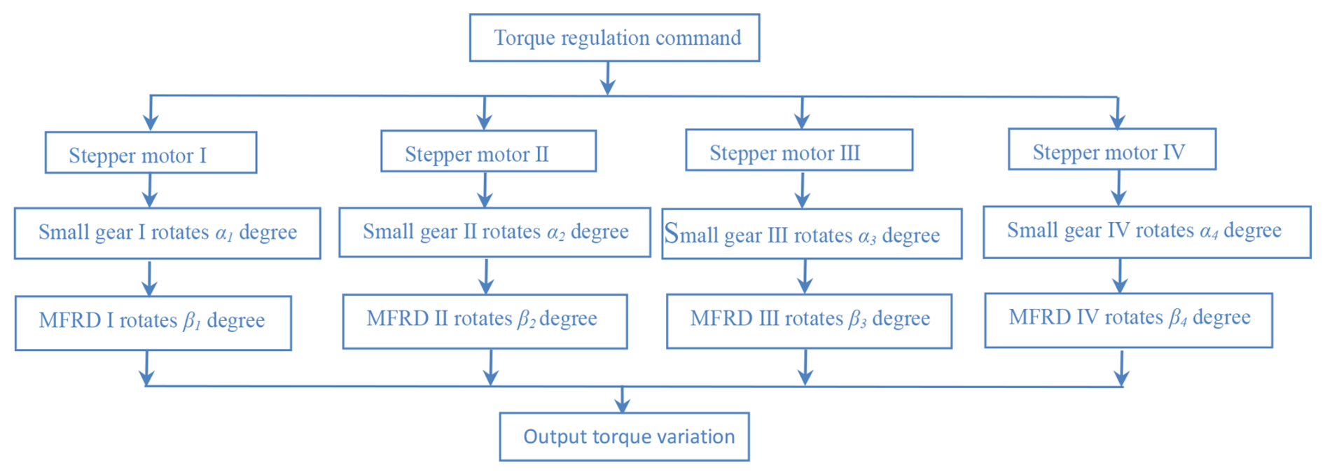
Upon receiving a control signal, the stepper motor(s) actuate the pinion gear to execute a rotational displacement αi, thereby inducing corresponding angular displacement βi in the MFRD. This kinematic transmission facilitates magnetic flux modulation, achieving precise regulation within individual disk assemblies. The resultant magnetic flux density enables the calculation of the unit torque output Ti. The aggregate torque output T demonstrates proportional dependence on both the constituent torque Ti and the multiplicity of disk assemblies, expressed as .
Benefiting from modular stacking architecture, the proposed coupler exhibits three principal advantages over conventional magnetic couplers:
-
Reduced axial size and simplified control structure. There is no axial movement between the PMD and CD, effectively reducing the overall axial size of the structure and simplifying the control mechanism.
-
Radial scalability under axial constraints. For equivalent torque capacity and power transmission, the number of permanent magnet concentric rings can be increased to compensate for reduced disk groups, enabling radial expansion – particularly advantageous for applications with large radial sizes but limited axial sizes without altering the overall structure.
-
Axial scalability under radial constraints. Conversely, augmenting the disk-group number permits radial dimension reduction while maintaining equivalent torque capacity, making this configuration suitable for confined radial spaces but large axial spaces.
As mentioned above, the proposed coupler has merits of high torque capacity that is flexible and simple in structure. It has broad application, especially in submarines, watercraft and ocean platforms.
2.2 Magnetic circuit analysis
In the analysis of magnetic couplers, both numerical and analytical methods are commonly employed. This paper primarily adopts the analytical approach to investigate and predict the performance characteristics of this novel magnetic coupler configuration. Afterward, the numerical method is adopted for further amendment, verification and parameter optimization.
The accurate determination of magnetic flux paths is fundamental for effective magnetic field conversion into equivalent circuit representations. Considering the inherent complexity of magnetic circuits, the following assumptions are implemented to facilitate analytical simplification:
-
The permanent magnet-generated magnetic field exhibits uniform distribution within the air gap.
-
Given the limited thickness of the air gap in the proposed coupler, the main magnetic flux passes perpendicularly through the permanent magnet, air gap, through-hole, disk body (MFRD) and CD (including the copper conductor).
-
The effective area of the copper conductor intersecting the magnetic field lines is used for calculating the conductor's area.
-
The effective magnetic flux-cutting area of copper conductors serves as the basis for conductor area calculations.
-
Magnetic circuit saturation effects are neglected.
-
The influence of temperature is considered negligible, with material reluctances maintained constant throughout the magnetic circuit.
-
All permanent magnets demonstrate identical structural and material properties, arranged uniformly within the PMD to ensure homogeneous eddy current distribution.
-
For computational simplification, only flux paths parallel to the disk thickness direction (CD, MFRD, PMD) are considered in regions overlapping with permanent magnet projections onto these disk components.
To facilitate follow-up analysis and calculations, it is essential to define the structural parameters in conjunction with Figs. 1, 2 and 3. In each PMD, the PMs are arranged radially and evenly in two concentric circles, with 12 PMs in each circle. The outer and inner radius of the PMs are denoted as r1 (or r3) and r2 (or r4), respectively. The arc length spacing between any two PMs, which is equal to the arc length of each PM of the same radius, is uniform in the radial direction.
A portion of the magnetic flux lines generated by the PMs passes through the through-hole and closes the magnetic circuit. These lines are produced by the PMs' projections on the CD. Simultaneously, other flux lines are guided by the magnetic flux return device (MFRD) and close the magnetic circuit. These lines are generated by the part of the PMs shielded by the MFRD body. By adjusting the size of the effective area of the PMs (i.e., the magnetization direction) that the MFRD shields, the number of magnetic flux lines reaching the CD can be regulated. Due to the synchronous variation of two PMs in corresponding radial positions, each pair of PMs in the same radial direction can be considered equivalent to a single PM, with an effective area equal to the sum of the two.
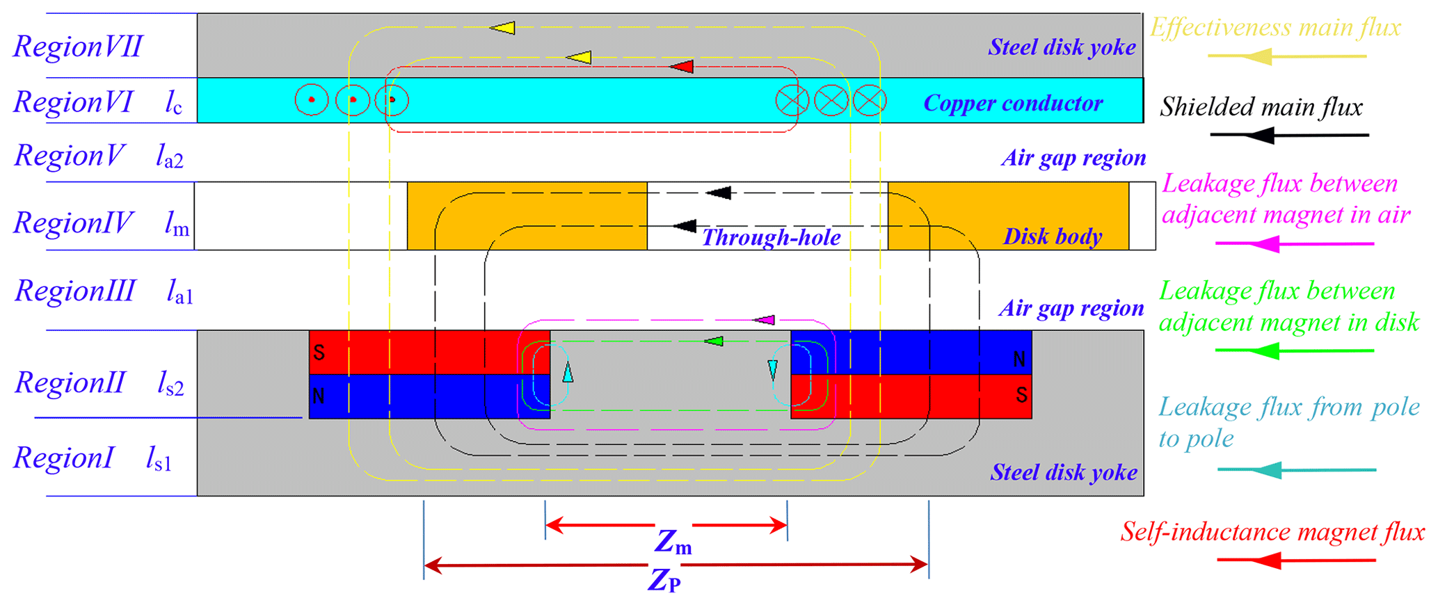
For convenience of calculation and analysis, the three-dimensional configuration is transformed into a two-dimensional equivalent model at the average radius () of the fan-shaped PMs, as illustrated in Fig. 5. The average PM pole arc length Zm and pole pitch Zp are expressed as follows:
3.1 The calculation of eddy current
Under the action of a rotating alternating magnetic field, eddy current distributions are induced on the copper conductor surface. The spatial extent of each induced region geometrically corresponds to the orthogonal projection area of individual permanent magnets onto the conductor plane, under the assumption of negligible fringing flux effects. For computational tractability, these distributed eddy current regions are conventionally simplified as concentric annular elements with equivalent projected areas.
As demonstrated in Fig. 3, the PMD incorporates dual concentric arrays of radially oriented magnets. This configuration induces corresponding dual-ring eddy current patterns on the conductor surface, as visualized in Fig. 6a. Through analysis of the operational mechanism described in Sect. 2, it can be mathematically demonstrated that the paired eddy current rings at matching radial positions exhibit synchronous spatiotemporal variations. To facilitate analytical modeling, this coupled system may be effectively represented by a single equivalent annular current region characterized by an equivalent eddy current ring radius r, as illustrated in Fig. 6b.
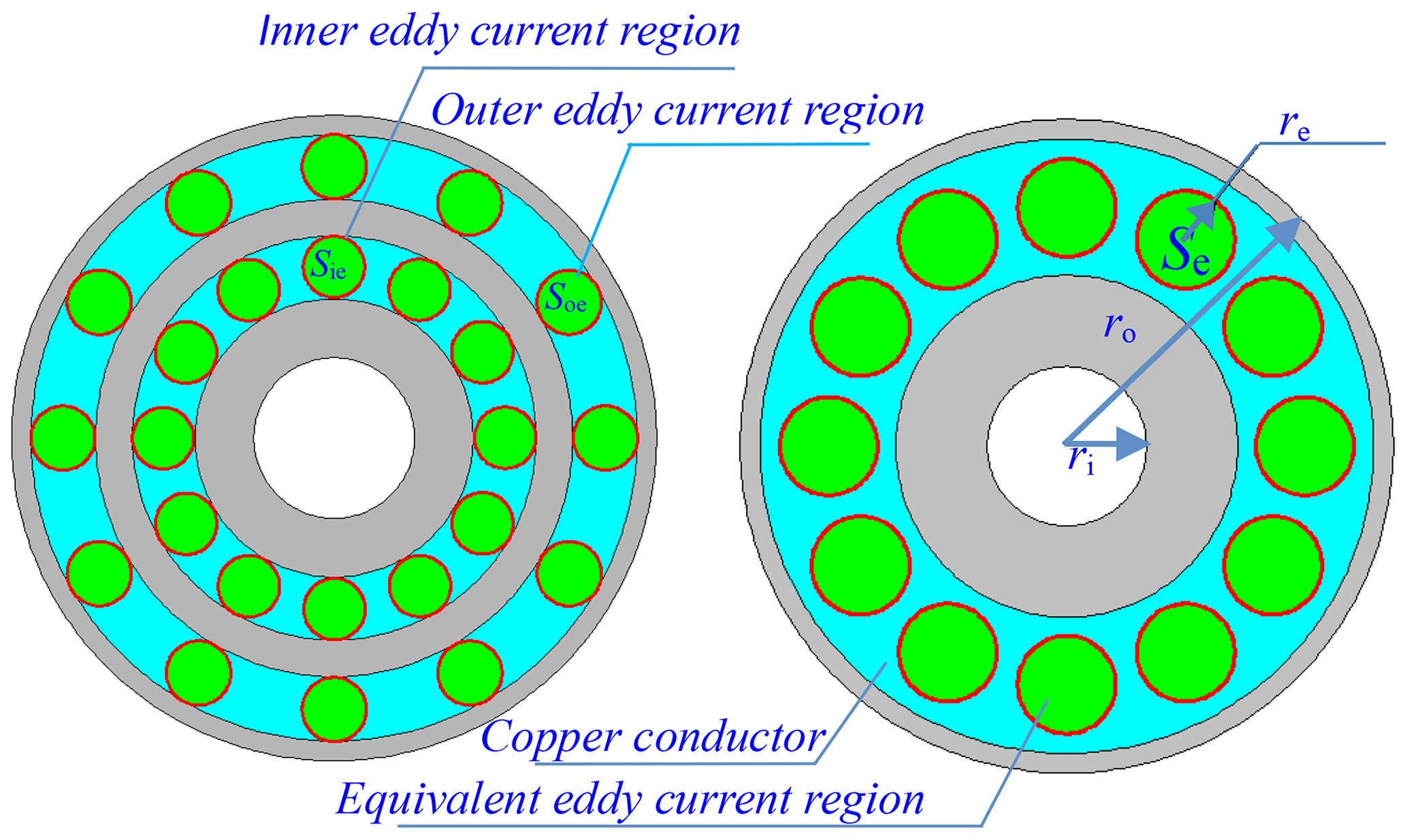
Figure 6The distribution schematic drawing of the initial eddy current rings and the equivalent one.
Consequently, the equivalent eddy current region area Se is defined as the arithmetic sum of the inner Sei and outer Seo eddy current regions:
However, due to the irregular magnetic flux distribution in practical operation, the fringing effect becomes non-negligible when calculating the equivalent eddy current region Se. To address this three-dimensional fringing effect, the Russell–Norsworthy correction factor kc is introduced (Liu et al., 2018). This correction method establishes an equivalence between the actual eddy current region area and the product of kc and the effective PM exposure area Sp, expressed as
The Russell–Norsworthy correction factor kc is given by
where Sp represents the effective exposure area of a single PM.
As derived from the operational principles and structural parameters discussed in previous sections, the magnitude of Sp demonstrates angular dependence within the rotational range of θ=0–15°. This relationship can be mathematically described as
Notably, both the shielded PM area Ss and the effective exposure area Sp exhibit angular dependency during rotational operation. These parameters can be expressed through the following parametric equation:
where SM denotes the maximum effective area of a single PM.
As illustrated in Fig. 3, all permanent magnets are arranged in two concentric circular arrays with alternating N and S poles in a cyclic axial magnetization pattern. When relative rotational motion occurs between the CD and PMD, the copper conductors intercept the magnetic flux lines, resulting in a periodic variation of magnetic flux Φ. The maximum magnetic flux Φ is established in the eddy current region when the PMD and CD maintain relative static alignment. This flux magnitude progressively decreases to zero as relative rotation initiates between the two disks. Following one complete mechanical cycle, the flux density gradually recovers to Φ through magnetic field realignment. This periodic variation can be mathematically expressed as
where (rad s−1), Be is the effective air-gap flux density, p is the number of PM pole pairs, and ω and Δω are the magnetic field variation angular velocity and slip angular velocity difference, respectively.
In light of Faraday's law of electromagnetic induction, the induced electromotive force Ei generated by rotating alternating magnetic field is
According to skin effect's law, the resistance of the eddy current ring generated on the copper conductor is calculated as follows, taking both radius re and correctional skin depth Δh∗ into account (Erasmus and Kamper, 2017):
The distribution of the eddy current is not uniform on the copper conductor; it tends to concentrate more on the surface as the frequency of the eddy current changes increases. The magnitude of skin depth depends on factors such as the thickness of the copper conductor, the slip and the conductor material, so skin factor ks should be taken into account, which is proposed in literature (Cheng et al., 2020). The skin factor is proposed by
where the numerical value of the correctional skin depth Δh∗ is equal to the product of skin factor ks and skin depth Δh (Lubin and Rezzoug, 2015). The skin depth Δh can be further obtained by
so that
3.2 The establishment of the equivalent magnetic circuit model
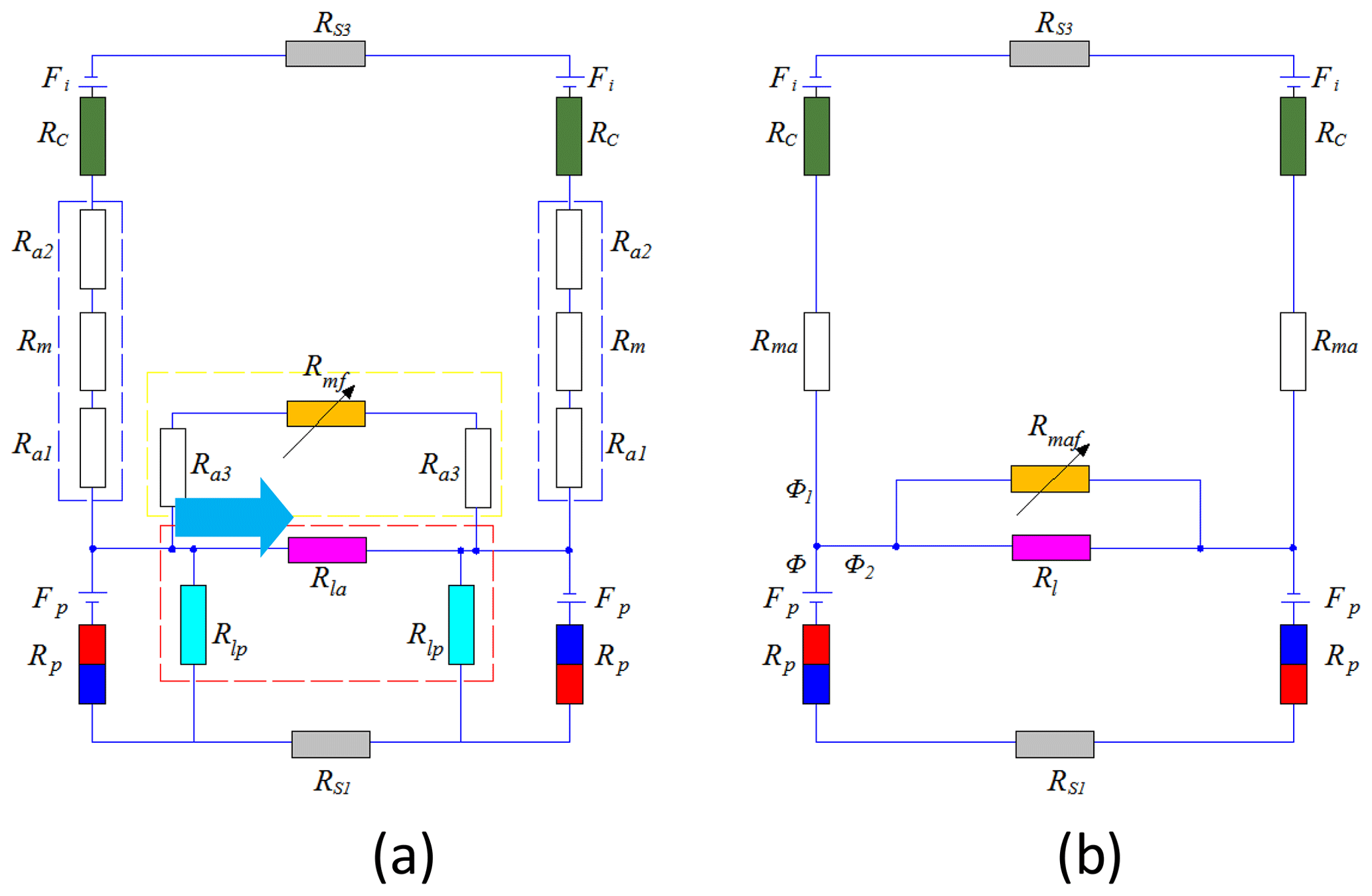
Accurate magnetic flux path analysis constitutes the foundational step for establishing equivalent magnetic circuit models. Based on the operational principles and flux distribution characteristics elucidated in previous sections, we develop an equivalent magnetic circuit model for the proposed coupler, as illustrated in Fig. 6a. Considering the axial symmetry of the magnetic circuit configuration, it is methodologically valid to analyze a single N–S pole pair for computational simplification. In this model, Fp represents the permanent magnet's magnetomotive force, analogous to a voltage source in electrical circuits, while Fi denotes the induced current's magnetomotive force in the branch circuit.
To further streamline the analysis, reluctance consolidation are made: the air-gap reluctance (dashed blue box in Fig. 7a) is integrated into Rma in the simplified model (Fig. 7b), the leakage reluctance components (dashed red box) are aggregated into Rl, and dual reluctances Ra3 and Rmf (dashed yellow box) combine to form Rmaf. The mathematical derivation governing these topological simplifications is systematically detailed in Sect 2.2, ensuring the integrality of the model reduction process.
The induced current generates a counteracting magnetic field that opposes the permanent magnet field, enabling the total equivalent magnetomotive force Fe to be expressed as
where ki represents the eddy current conversion coefficient, an empirical parameter typically ranging from 1.2 to 2.5 (Belguerras et al., 2021). The induced current can be calculated by
and its effective value can be derived from
3.3 The calculation of reluctance
Based on the magnetic flux path analysis presented in Figs. 5 and 7, the reluctance of several part of the equivalent magnetic circuit is formulated (respectively) as the following equations, where Rc represents the reluctance of the copper conductor with path lc, Rp represents the reluctance of the PM with path ls2 and Ra3 represents the reluctance of the air gap with path la1. Similarly, Ra1, Rm and Ra2 represent the reluctance of the air gap with path la1, lm and la2, respectively, which can amount to reluctance Rm of the air gap for convenient calculation:
and
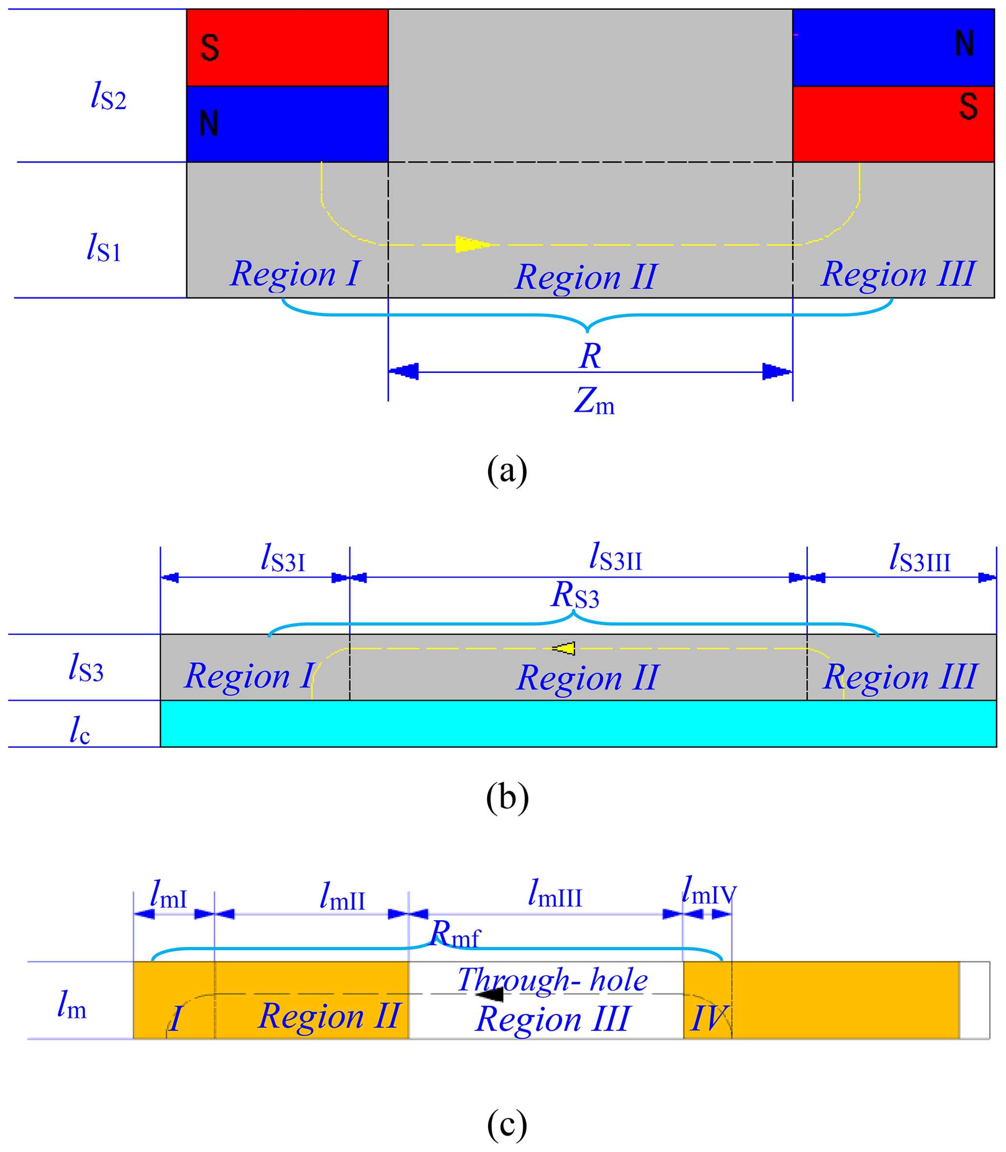
Figure 8The schematic drawing of the magnetic flux path partitioned for magnetic resistance calculation.
As illustrated in Fig. 8a, the magnetic flux path within the PMD sequentially traverses Region I, II and III, hence enabling segmentation of the flux path into three distinct calculation domains. Similarly, Fig. 8b demonstrates an analogous three-segment flux path division. The corresponding reluctance components RS1 and RS3 are derived through the following expressions:
By integrating Eqs. (19) and (20) with the fundamental magnetic circuit equation (Eq. 1), they can be derived as
where
so that
It should be emphasized that the magnetic flux path length lS3 II is not constant, as it varies with the relative rotation angle θ between the MFRD and PMD. Specifically, lS3 II reaches its minimum value Zm when the through-holes completely align with the permanent magnets (at θ=15°), whereas it attains the maximum value Zp when the permanent magnets are fully shielded by the MFRD disk body (at θ=0°).
Therefore,
However, the magnetic flux path within the MFRD requires subdivision into five distinct segments, as illustrated in Fig. 8c. Due to the presence of through-holes in Region III, the magnetic flux lines circumvent these through-holes, resulting in curved trajectories (Fig. 8c shows planar projections of these three-dimensional paths) rather than the idealized straight paths. Consequently, the actual magnetic flux path length in Region III deviates from lm3, necessitating the introduction of an empirical correction coefficient kf. This coefficient, determined through subsequent FEM simulations, modifies the path length as

Figure 9The schematic drawing of the leakage reluctance path for the adjacent magnet in the air.
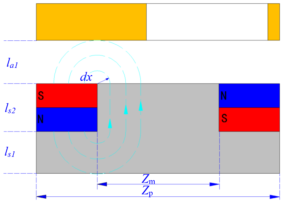
Figure 10The schematic drawing of the leakage reluctance path for a single magnet from pole to pole.
As illustrated in Figs. 9 and 10, the leakage reluctance may be classified into two primary categories: magnet-to-magnet leakage reluctance (Fig. 9) and inter-pole leakage reluctance (Fig. 10). The first category originates from the flux path between adjacent permanent magnets, while the second category arises from the magnetic flux interaction across different poles.
For simplifying the analysis, as demonstrated by the dashed blue box in Fig. 7a, the dual Rlp reluctances are connected in series configuration prior to their parallel combination with reluctance Rla. This topological arrangement enables equivalent simplification to a single reluctance Rl. Likewise, within the dashed red box of Fig. 7a, reluctances Rm, Ra1 and Ra2 form a series connection that can be equivalently reduced to a composite reluctance Rma. The resulting simplified magnetic equivalent circuit is depicted in Fig. 7b. Through systematic derivation following the established methodology, these equivalent reluctances can be mathematically expressed as follows:
Further, as illustrated in Fig. 7b, reluctance Rl forms a parallel connection with reluctance Rmfa. This configuration enables their equivalent reduction to a composite reluctance Rlmfa for subsequent calculations, which is derived as
Furthermore, the magnetic flux relationship can be mathematically expressed as
Based on Kirchhoff's magnetic circuit law, the nodal equations governing the equivalent magnetic circuit in Fig. 7b are established as follows:
The principal magnetic flux Φ1 and effective magnetic flux density B can be mathematically derived as
Notably, the principal magnetic flux Φ1 demonstrates non-constant characteristics due to its dependence on the variable reluctance Rlmaf within the magnetic circuit. This parameter Rlmaf is inherently governed by the angular variation θ, as expressed in the reluctance–air-gap relationship.
3.4 The calculation of eddy current loss
Under alternating magnetic field conditions, an induced current I is generated within the copper conductor, subsequently producing eddy current losses that are dissipated as thermal energy. The instantaneous eddy current loss density in each subregion Se can be expressed as
Hence, the total eddy current loss for the entire copper conductor disk is therefore obtained through spatial integration:
The angular θ dependence of the total eddy current loss can be subsequently derived as
For the proposed coupler comprising n stacked compound-disk assemblies, the cumulative eddy current loss becomes
3.5 The calculation of torque output
The magnetic field energy storage for a single compound-disk group can be expressed as
where v represents the effective region of the magnetic field distribution.
Based on energy conservation principles, the energy transfer equation for the magnetic coupling system with one compound-disk group is established as
According to Newton's third law of motion, the magnitudes of the tension forces T1 and T2 must satisfy the equilibrium condition T1=T2, where the subscripts denote
The magnetic field remains relatively steady when one group of compound disks reaches a steady state, so it can be deduced as
Under steady-state conditions, the mathematical model describing the output torque for a single set of compound disks is formulated as
Through the systematic derivation of the preceding analysis, the complete torque model for the proposed coupler is established as
As demonstrated by the formula above, the total output torque of the proposed coupler is derived from the superposition of individual compound-disk assemblies under varying θi conditions. Consequently, the torque capacity can be enhanced by increasing either the number of compound-disk groups or the radial arrangement density of permanent magnets. This structural flexibility enables the coupler to accommodate size-constrained application scenarios.
The mathematical model governing the output torque of the proposed magnetic coupler has been theoretically derived. However, this derivation fundamentally relies on precise magnetic flux path analysis and validated assumptions. To rigorously verify the analytical framework, finite element method (FEM) simulations were systematically conducted to examine the electromagnetic field distributions under operational conditions. Following the successful validation of the theoretical model, parametric optimization of the coupler's critical dimensions emerges as an essential subsequent phase in the design iteration process. For the verification studies and preliminary design implementation, the following simulation hypotheses were made:
-
Thermal simplification. Temperature-dependent effects were excluded based on preliminary thermal analysis indicating maximum operational temperatures below 80 °C (PM Curie points exceed 320 °C).
-
Material linearity. All soft magnetic materials maintained constant relative permeability with negligible hysteresis losses.
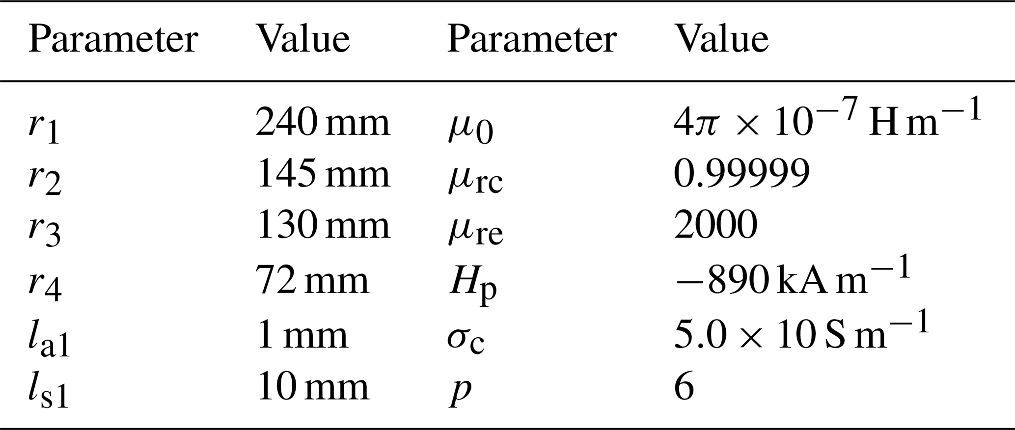
In addition, for computation resource saving, the FEM models are adopted adaptive refinement mesh (maximum element size 50 mm; minimum 0.5 mm) and vector potential boundaries. The stable and convergent simulation results are adopted as valid data and so that the successive iteration error is limited within the set value (ε≤0.003). Other details of the geometric parameter are listed in Table 1.
4.1 2D magnetic flux path analytical model for verification
The working principle of the proposed magnetic flux-regulation coupler is predicated on the hypothesis that a fraction of the primary magnetic flux traverses the through-hole of the MFRD to interact with the copper conductor, while the residual flux is channeled through the MFRD body back to the PMD. The flux partitioning between these two paths exhibits angular dependency governed by the relative rotation between the MFRD and PMD. To validate this hypothesis, a two-dimensional finite element method (2D FEM) is established for further magnetic flux path analysis.
A seven-layer two-dimensional FEM model was constructed in accordance with the cross-sectional configuration illustrated in Fig. 3. Material selection critically influences the coupler's performance: the PMD and CD employ low-carbon steel-1008, while the MFRD utilizes silicon steel (relative permeability is 7000). The conductor utilizes copper (bulk conductivity 5.8×10⁷ siemens m−1), and the permanent magnets are Ndfe35 with axial magnetization. Magnetostatic simulations revealed two distinct flux pathways (Fig. 11): the primary path (dashed blue contour) originates from the N pole, sequentially traverses the through-hole air gap, copper layer and the CD, and returns via the air gap before terminating at the S pole; the secondary path (dashed yellow contour) completes the magnetic circuit through the minimized air gap and MFRD body, effectively forming a magnetic short circuit due to the high-permeability silicon steel.
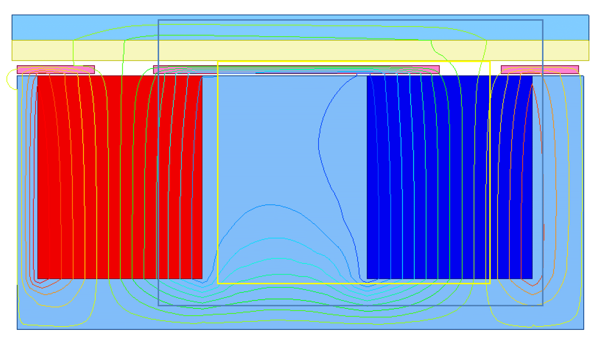
This flux bifurcation mechanism confirms that the through-hole geometry serves as an effective magnetic reluctance regulator. quantitative analysis demonstrates that adjusting the through-hole dimensions enables precise flux density regulation, thereby experimentally validating the operational hypothesis presented in Fig. 5.
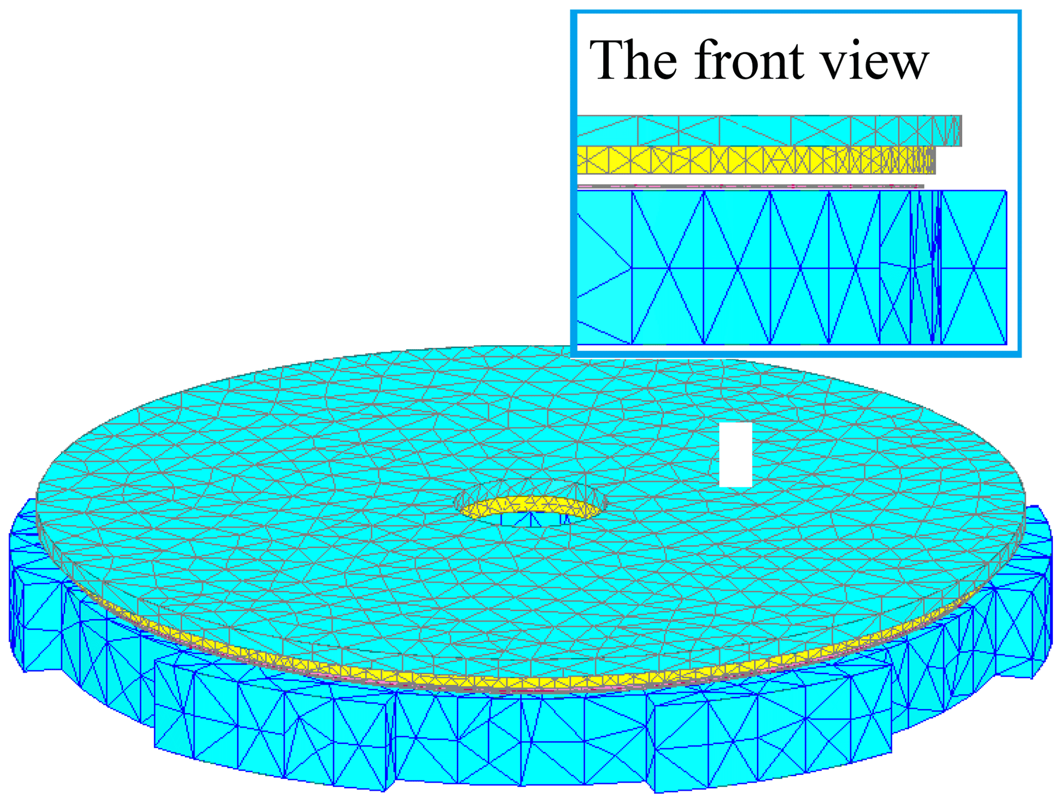
4.2 Description of 3D FEM
To investigate the electromagnetic characteristics of the proposed coupler, a transient three-dimensional finite element method (3D FEM) model was established with the same material mentioned in the 2D model. For angular rotation simulation, the physical bearing that integrates the PMD with the MFRD was substituted by a 1 mm air gap in the FEM model, as illustrated in the front view of Fig. 12. This simplification is justified since the bearing demonstrates negligible influence on magnetic flux distribution. The PMD configuration consists of two concentric circular arrays containing 12 uniformly distributed PMs per array.
The copper conductor thickness was determined by considering the skin effect requirements. Based on the skin depth formula for copper (), the calculated skin depth h* at 30 rpm operation is 1.56 mm. To ensure adequate current penetration, the copper thickness was selected as 5 mm, significantly exceeding the theoretical skin depth.
Air-gap optimization followed two criteria: (1) minimizing magnetic leakage through reduced gap dimensions and (2) preventing PM demagnetization from eddy current heating. Consequently, a 3 mm air gap was implemented between the copper conductor and MFRD, achieving a balance between magnetic efficiency and thermal protection.
Notably, the simulation accounted for eddy current effects exclusively in the copper conductor. Material properties were assumed to remain stable throughout the analysis. Figure 12 presents the meshed 3D FEM model of a single disk module in the proposed coupler system.
4.3 Field analysis of the proposed coupler in transient
The MFRD serves as a critical component in the proposed coupler design, operating on the fundamental principle that magnetic flux preferentially follows the path of least magnetic reluctance. This magnetic circuit behavior has been experimentally validated through comparative analysis of Fig. 13a and b, where 3D FEM simulations demonstrate a 65.8 % reduction in maximum magnetic flux density (from 282 to 96.5 T) when the angular displacement θ increases from 0 to 15°.
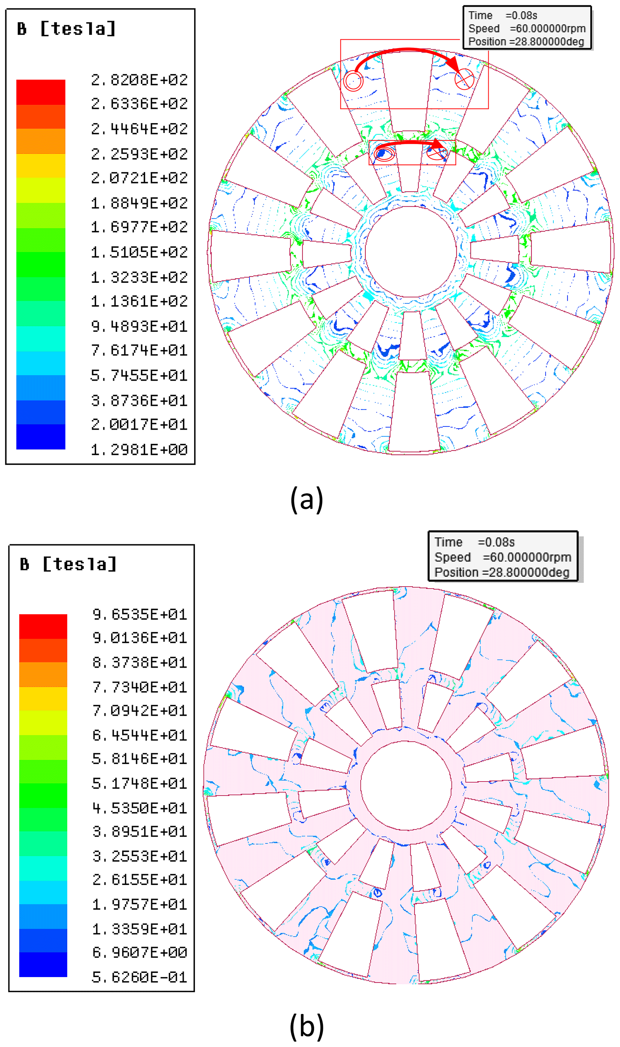
Figure 13The angular dependence of magnetic flux density distribution on the MFRD under different angular displacements: (a) θ=0° with complete PM shielding by the MFRD and (b) θ=15° with full PM exposure to the copper conductor.
In Fig. 13a, PMs are fully shielded by the MFRD when θ=0°. The main magnetic flux acts on the perpendicular direction to the MFRD body; meanwhile, main magnetic lines originate from the N pole, returning back to the S pole along the path of the MFRD body (described in the red line rectangle), so that magnetic flux density is greater in this area than in the other area. This path almost aligned with the outer arc of the through-hole so that it can be replaced by the outer arc larc in calculation for simplification. Hence, the correction coefficient kf in Eq. (30) can be calculated by combining with the parameters shown in Table 1 and Eq. (1): . The magnetic flux density decreases on the MFRD body as θ increases.
By contrast, as presented in Fig. 13b, PMs are directly exposed to the copper conductor when θ=15°. The main magnetic flux acts on the perpendicular direction to the copper conductor; the main magnetic lines originate from the N pole, passing through the air gap, copper conductor and CD successively. It returns to the S pole along the backward path, and the only leakage flux reaches the MFRD body so that the magnetic flux density is low on the MFRD body.
This angular-dependent flux modulation mechanism confirms the MFRD's effectiveness in governing magnetic circuit reluctance through geometric parameterization of the through-hole feature.
According to electromagnetic theory, rotating alternating magnetic fields induces surface eddy currents in the copper conductor, predominantly concentrated perpendicular to the magnetic pole orientation. The spatial extent of each eddy current region corresponds to the product of the Russell–Norsworthy correction factor kc and the perpendicularly projected area of PMs onto the copper surface.
As evidenced by the 3D FEM simulations in Fig. 14b (θ=15°), two concentric eddy current regions emerge with excellent agreement between numerical results and theoretical predictions. The outer eddy current region has 190 % greater intensity than the inner region (2.91×10⁷ A m−2 vs. 9.72×10⁶ A m−2). This phenomenon is attributable to the 2.68-times larger effective projection area of outer-circle PMs compared to its inner-circle counterparts.
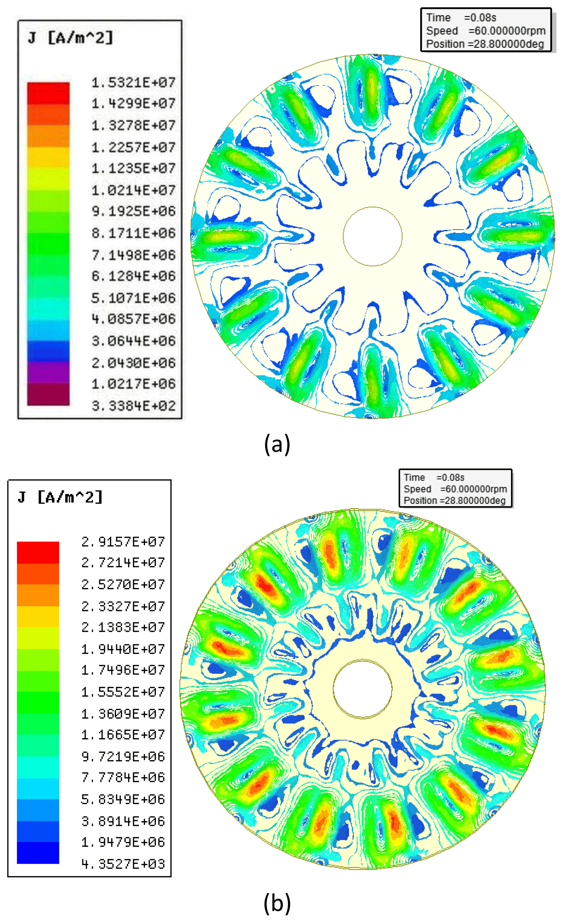
Figure 14Eddy current density distribution on the copper conductor under different angular displacements: (a) complete magnetic shielding configuration (θ=0°) with PMs fully enclosed by MFRD and (b) activated eddy current state (θ=15°) showing PMs–Cu direct exposure.
In contrast, Fig. 14a (θ=0°) reveals negligible eddy current formation (density < 1.53 × 10⁷ A m−2, but it appears on only a very tiny region), resulting from magnetic flux confinement within the MFRD. Only a little flux leaks through to the copper conductor in this aligned configuration, as quantified by flux linkage analysis.
4.4 Torque related to the arrangement of PMS
The proposed coupler exhibits significant structural flexibility, particularly in its capacity for torque enhancement through radial multi-layer PM arrangements. As demonstrated in Fig. 3, two concentric PM arrays with distinct magnetization patterns can be radially integrated: (1) same-polarity alignment (SPA) where identical poles align across concentric arrays and (2) different polarity alignment (DPA) with opposing poles in corresponding radial positions. Figure 15 presents the comparative torque-angle characteristics of these configurations, revealing three critical observations:
-
Both configurations exhibit similar torque-angle trends, with peak torque occurring at θ=15°.
-
SPA generates 1.7 % higher maximum torque (418 N m) compared to DPA (411 N m).
-
The torque differential results from intensified magnetic flux leakage between radially opposed PM poles in the DPA configuration.
In addition, the angular regulation characteristics demonstrate two obvious operational regimes: (1) dead zone (0° ≤ θ < 7°): negligible torque output (<2 % of the maximum vale); and (2) effective regulation zone (7° ≤ θ ≤ 15°): torque increases non-linearly with θ increase.
This angular dependence establishes an effective torque regulation range of θ=7–15°, enabling precise control through angular displacement modulation. The dead zone provides torque cut-off, while the effective regulation zone achieves torque regulation via angular displacement variation, and the SPA of the PMs is a priority choice for the proposed coupler.
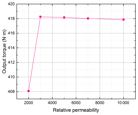
4.5 Torque related to the relative permeability of MFRD
It is critical that the MFRD be fabricated from high-permeability soft magnetic materials in this novel coupling configuration. As illustrated in Fig. 16, the maximum output torque (θ=15°) in steady-state operation demonstrates a bifurcated trend with increasing relative permeability. The torque increases 2.4 % from 408 to 418.6 N m within the lower permeability range (μrs = 2000–3000), followed by a marginal falling tendency (down to 417.3 N m) at higher permeability values (μrs = 3000–10 000). This phenomenon can be attributed to the insufficient flux-guiding capability of the MFRD when employing materials with μrs < 3000, where a significant portion of magnetic flux fails to effectively couple with the conductive copper elements. The subsequent torque enhancement correlates directly with improved flux guidance at intermediate permeability levels. However, when μrs exceeds 3000, the MFRD achieves near-optimal flux channeling, resulting in torque stabilization despite further permeability increases beyond this critical permeability threshold.
Silicon steel, a common soft magnetic material characterized by high permeability (μrs = 7000–10 000, depending on alloy composition and processing parameters), represents an optimal candidate for MFRD implementation. Comparative analysis of commercial grades suggests that material formulations yielding μrs ≈ 7000 provide the optimal balance between magnetic performance and manufacturing feasibility for the MFRD.
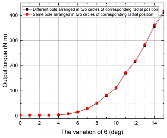
Figure 15Angular θ dependence of output torque characteristics: same and different polarity alignment.
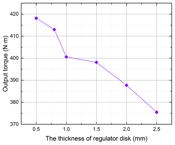
4.6 Torque related to the thickness of MFRD
Under the condition of constant air-gap thickness between the copper conductor and MFRD, the maximum output torque at θ=15° in steady-state operation decreases with increasing MFRD thickness, as illustrated in Fig. 17. This phenomenon can be attributed to two primary factors: (1) thinner MFRD configurations already satisfy the fundamental functional requirements and (2) the overall air gap between the PMs and copper conductor enlarges proportionally with MFRD thickness augmentation, thereby reducing magnetic flux density and consequent torque generation. However, excessively thin configurations (below 0.8 mm) compromise structural integrity due to insufficient global stiffness and pose manufacturing challenges. Through comprehensive parameter analysis considering both electromagnetic performance and mechanical feasibility, the optimal MFRD thickness is determined to be 0.8 mm, achieving balanced torque output and structural reliability.
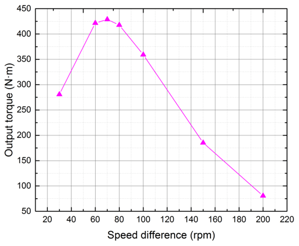
4.7 Torque related to the speed difference
The variation of speed difference between the PMD and MFRD will lead to the variation of the eddy current on the copper conductor, which in turn eventually leads to the variation of output torque of the coupler. Therefore, it is important to find the law of torque related to speed difference for the proposed coupler. From the 3D FEM result of the proposed coupler in Fig. 18, it is obviously that the output torque increase as speed difference increases at first and reaches the peak; then it decreases dramatically as speed difference increases. The maximum output torque of the proposed coupler gets to peak (426.4 N m) at the speed difference of about 70 rpm. The cause leading to this tendency may be explained as follows: with the speed difference increase, the induced magnetic field increases, with the eddy current increasing as well, which enhances the original magnetic field so that the output torque increases at first. Then, after the speed difference increases further, the induced magnetic field increases and affects the original magnetic field. This results in some magnetic lines no longer passing the copper conductor vertically. The greater the speed difference, the greater the effect, so that the output torque decreases.
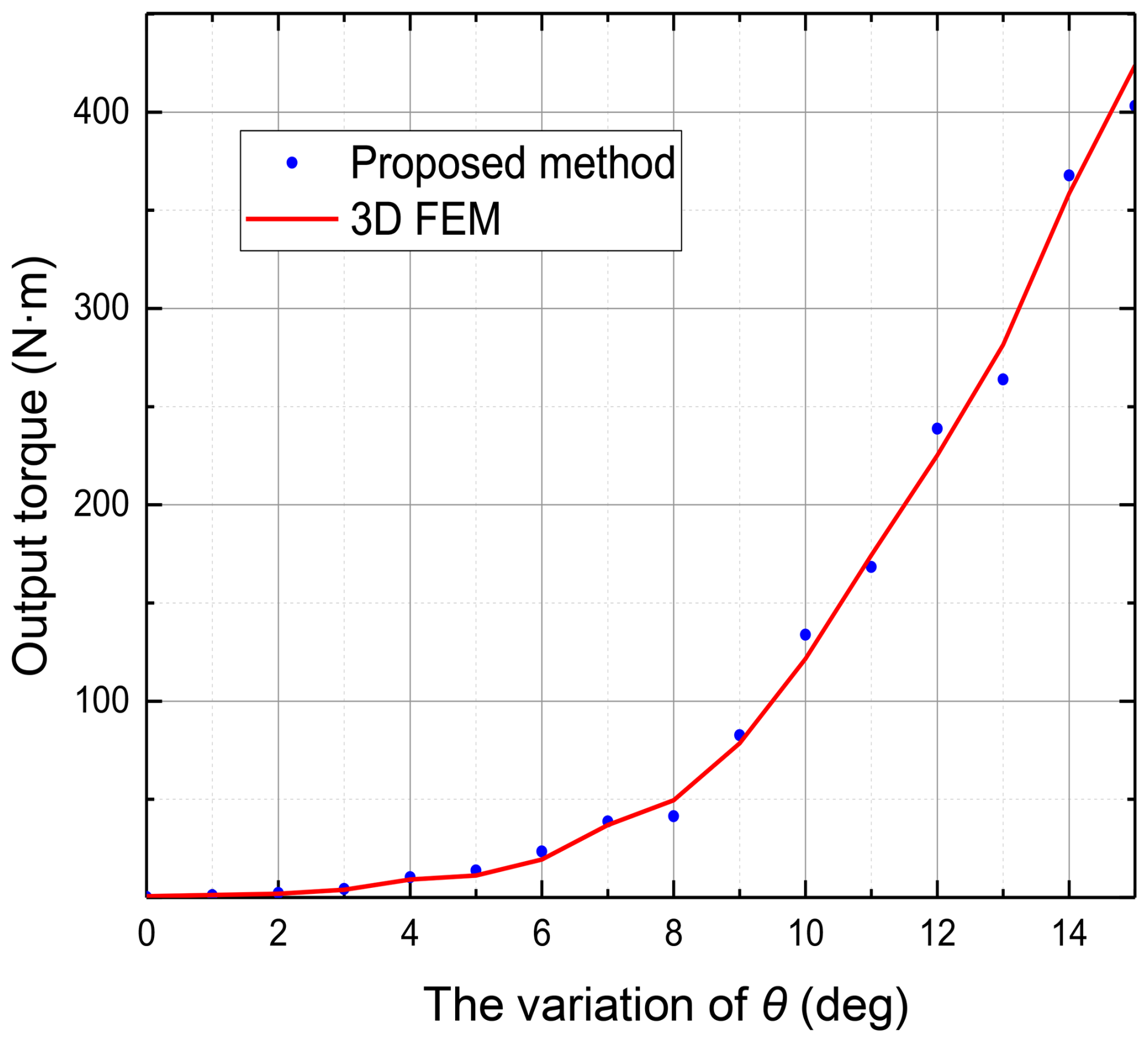
4.8 The torque comparison between the analytical model and 3D FEM
By combining the fundamental parameters listed in Table 1 with the optimized operational parameters described earlier and the output torque analytical model derived from Eq. (6), we present a comparative analysis of the analytical model and 3D FEM simulations in Fig. 19. Both methodologies demonstrate strong agreement in predicating the increasing trend of torque with respect to θ, with the maximum error between the two methodologies being 9.2 %. These findings collectively suggest that the proposed analytical model provides a reliable and computationally efficient method for the preliminary design phase of the novel coupler.
This study proposed a novel multi-disk magnetic flux-regulatable coupler, addressing critical limitations in conventional magnetic transmission systems. The proposed architecture demonstrates three fundamental advancements: (1) a stationary axial configuration enabling torque capacity expansion through concentric disk stacking, effectively eliminating structural scalability constraints; (2) an innovative flux-regulation mechanism employing rotational alignment of high-permeability regulator disks with through-hole features, achieving 0–418 N m continuous torque regulation within a range of 7–15° angular displacement; and (3) a hybrid analytical FEM modeling approach integrating three-dimensional edge effects and dynamic eddy-current counter fields, validated through comprehensive finite element simulations.
Key parametric optimizations reveal critical design insights: optimal MFRD performance occurs at a relative permeability of μrs=7000 with 0.8 mm thickness, while maximum torque output (426.4 N m) is attained at 70 rpm speed differential. The modular architecture demonstrates exceptional scalability and extensive application scenarios. Comparative analysis of permanent magnet arrangements indicates same-polarity alignment (SPA) and generates 1.7 % higher torque than differential alignment (DPA), emphasizing the importance of leakage flux management.
The developed analytical model demonstrates strong correlation with 3D FEM results (the maximum error is 9.2 %). Structural advantages include axial size reduction compared to conventional axial displacement couplers, coupled with simplified control through pure rotational adjustment, and modular architecture demonstrates exceptional scalability and extensive application scenarios.
This research establishes a foundation for high-torque magnetic transmission in space-constrained industrial applications, particularly marine propulsion and heavy machinery. Future work will focus on prototype validation under dynamic loading conditions and thermal structural co-optimization for high-cycle applications. The co-design methodology provides a template for developing next-generation magnetic transmission systems with enhanced torque density and operational flexibility.
| Electromagnetic parameters | |
| P | Number of permanent magnet (PM) pole pairs |
| Φ | Maximum magnetic flux (Wb) |
| σc | Electrical conductivity of copper (S m−1) |
| Be | Effective air-gap flux density (T) |
| μ0 | Vacuum permeability ( H m−1) |
| μrc | Relative permeability of copper (dimensionless) |
| μrp | Relative recoil permeability of PM (dimensionless) |
| μrs | Relative permeability of flux regulator (dimensionless) |
| Hp | Coercive force of the PM (A m−1) |
| Fp | PM magnetomotive force (A per turn) |
| Fe | Total equivalent magnetomotive force (A per turn) |
| Fi | Single eddy current region magnetomotive force (A per turn) |
| Geometric dimensions | |
| r1,r2 | Outer/inner radii of outer PM ring (mm) |
| r3,r4 | Outer/inner radii of inner PM ring (mm) |
| ro,ri | Outer/inner radii of conductor disk (CD) (mm) |
| re | Equivalent eddy current ring radius (mm) |
| Geometric dimensions | |
| ls1 | PM disk (PMD) yoke axial thickness (mm) |
| ls2 | PM magnetization length (mm) |
| la1 | PMD–MFRD air gap (mm) |
| lm | MFRD axial thickness (mm) |
| la2 | MFRD–CD air gap (mm) |
| lc | Conductor layer thickness (mm) |
| ls3 | CD disk yoke axial thickness (mm) |
| larc | Outer arc of the through-hole (mm) |
| Zm | Average PM pole arc length (mm) |
| Zp | Pole pitch (mm) |
| Operational variables | |
| θ | Relative angular displacement between PMD and MFRD (°) |
| α, β | Stepper gear/MFRD rotation angle (°) |
| ω1, ω2 | Input/output shaft angular velocity (rad s−1) |
| Δω | Slip angular velocity difference (rad s−1) |
| ω | Magnetic field variation angular velocity (rad s−1) |
| Loss characterization | |
| Se | Equivalent eddy current area (mm2) |
| Sp | Effective PM exposure area (mm2) |
| Ss | Shielded PM area (mm2) |
| Sie, Soe | Outer/inner eddy current ring region area (mm2) |
| SM | Maximum effective area of single PM (mm2) |
| kc | Russell–Norsworthy correction factor (dimensionless) |
| ks | Skin factor (dimensionless) |
| Δh | Standard skin depth (mm) |
| Δh* | Corrected skin depth (mm) |
| Pse | Single eddy region power loss (W) |
| Pce | Conductor disk total loss (W) |
The software code used in this study is not disclosed for the time being as it contains proprietary algorithms. However, it can be obtained from the author (email: zsq2350594@126.com) upon reasonable request.
The simulation data of this study are temporarily not disclosed due to the involvement of undisclosed patent information. However, they can be obtained from the author (email: zsq2350594@126.com) upon reasonable request.
All models were established and all data analyses were performed by SZ, who also wrote the draft of the paper under the supervision of CY. The paper was reviewed and edited by ZT and BL.
The contact author has declared that none of the authors has any competing interests.
Publisher's note: Copernicus Publications remains neutral with regard to jurisdictional claims made in the text, published maps, institutional affiliations, or any other geographical representation in this paper. The authors bear the ultimate responsibility for providing appropriate place names. Views expressed in the text are those of the authors and do not necessarily reflect the views of the publisher.
We thank the National Key Laboratory for funding and support.
This work is supported by the National Key Laboratory of High-end Equipment Mechanical Transmission Open Fund (SKLMT-MSKFKT-202331).
This paper was edited by Pengyuan Zhao and reviewed by two anonymous referees.
Aberoomand, V., Mirsalim, M., and Fesharakifard, R.: Design optimization of double-sided permanent-magnet axial eddy-current magnetic couplers for use in dynamic applications, IEEE Trans. Energy Convers., 34, 909–920, https://doi.org/10.1109/TEC.2018.2880679, 2019.
Ahmadi, I., Davarponah, M., Sladek, J., Sladek, V., and Moradi, M. N.: A size-dependent meshless model for free vibration analysis of 2D-functionally graded multiple nanobeam system, J. Braz. Soc. Mech. Sci. Eng., 46, 1–23, https://doi.org/10.1007/s40430-023-04580-5, 2024.
Belguerras, L. S., Mezani, S., and Lubin, T.: Analytical modeling of an axial field magnetic coupler with cylindrical magnets, IEEE Trans. Magn., 57, 1–5, https://doi.org/10.1109/TMAG.2020.3005949, 2021.
Cheng, X., Liu, W., Zhang, Y., Liu, S. T., and Luo, W. Q.: A concise transmitted torque calculation method for pre-design of axial permanent magnetic coupler, IEEE Trans. Energy Convers., 35, 938–947, https://doi.org/10.1109/TEC.2019.2963713, 2020.
Du, Y., Liu, H., Li, Y., Chen, J., and Liu, W.: Equivalent magnetic circuit analysis of doubly salient PM machine with II-shaped stator iron core segments, IEEE Trans. Appl. Supercond., 30, 1–5, 2020.
Erasmus, A. S. and Kamper, M. J.: Computationally efficient analysis of double PM-rotor radial-flux eddy current couplers, IEEE Trans. Ind. Appl., 53, 3519–3527, https://doi.org/10.1109/TIA.2017.2690986, 2017.
Jin, P., Tian, Y., Lu, Y., Guo, Y., Lei, G., and Zhu, J.: 3-D analytical magnetic field analysis of the eddy current coupling with halbach magnets, IEEE Trans. Magn., 56, 1–4, https://doi.org/10.1109/TMAG.2019.2950389, 2020.
Kong, D., Wang, D., and Li, W.: Analysis of a novel flux adjustable axial flux permanent magnet eddy current coupler, IET Electric Power Applications, 17, 181–194, https://doi.org/10.1049/elp2.12254, 2023.
Lz, Y., Yi, Z., and Mg, C.: Electromagnetic performance and thermal analysis of a novel permanent magnet fluxed-switching coupler, Int. J. Appl. Electromagn. Mech., 68, 123–140, https://doi.org/10.3233/JAE-210127, 2022.
Lubin, T. and Rezzoug, A.: Steady-state and transient performance of axial-field eddy-current coupling, IEEE Trans. Ind. Electron., 62, 2287–2296, https://doi.org/10.1109/TIE.2014.2351785, 2015.
Lubin, T., Mezani, S., and Rezzoug, A.: Two-dimensional analytical calculation of magnetic field and electromagnetic torque for surface-inset permanent-magnet motors, IEEE Trans. Magn., 48, 2080–2091, https://doi.org/10.1109/TMAG.2011.2180918, 2012a.
Lubin, T., Mezani, S., and Rezzoug, A.: Simple analytical expressions for the force and torque of axial magnetic couplings, IEEE Trans. Energy Convers., 27, 536–546, https://doi.org/10.1109/TEC.2012.2183372, 2012b.
Li, Y., Lin, H., Yang, H., Fang, S., and Wang, H.: Analytical analysis of a novel flux adjustable permanent magnet eddy-current coupling with a movable stator ring, IEEE Trans. Magn., 54, 1–4, https://doi.org/10.1109/TMAG.2017.2764260, 2018.
Liu, G., Ding, L., Zhao, W., Chen, Q., and Jiang, S.: Nonlinear equivalent magnetic network of a linear permanent magnet vernier machine with end effect consideration, IEEE Trans. Magn., 54, 1–9, https://doi.org/10.1109/TMAG.2017.2751551, 2018.
Meng, Z., Zhu, Z., and Sun, Y.: 3-D analysis for the torque of permanent magnet coupler, IEEE Trans. Magn., 51, 1–4, https://doi.org/10.1109/TMAG.2014.2359851, 2015.
Wang, J. and Zhu, J.: A simple method for performance prediction of permanent magnet eddy current couplings using a new magnetic equivalent circuit model, IEEE Trans. Ind. Electron., 65, 2487–2495, https://doi.org/10.1109/TIE.2017.2739704, 2018.
Wang, J., Lin, H., Fang, S., and Huang, Y.: A general analytical model of permanent magnet eddy current couplings, IEEE Trans. Magn., 50, 1–9, https://doi.org/10.1109/TMAG.2013.2279073, 2014.
Yang, C., Peng, Z., Tai, J., Zhu, L., Telezing, B. J. K., and Ombolo, P. D.: Torque characteristics analysis of slotted-type eddy-current couplings using a new magnetic equivalent circuit model, IEEE Trans. Magn., 56, 1–8, https://doi.org/10.1109/TMAG.2020.3009479, 2020.
- Abstract
- Introduction
- Working principle and theoretical analysis
- The establishment and calculation of equivalent magnetic circuit model
- Verification and optimization of the proposed coupler
- Conclusion
- Appendix A: Nomenclature
- Code availability
- Data availability
- Author contributions
- Competing interests
- Disclaimer
- Acknowledgements
- Financial support
- Review statement
- References