the Creative Commons Attribution 4.0 License.
the Creative Commons Attribution 4.0 License.
 | 26 Jun 2026
Research on compliance control strategy of elbow–wrist rehabilitation robot based on information fusion
Hui Bian
Hang Shang
Peixuan Du
Mingzhi Wang
Runyang Liu
Ze Luo
Compliance control is the key to human–robot physical interaction, which can improve the safety and comfort of robot-assisted rehabilitation. Aiming to address the problems of the large time delay and low compliance of the system caused by the slow speed of motion intention recognition based on the force signal, this paper integrates the force signal and the surface electromyography (sEMG) signal as the input of the elbow–wrist rehabilitation robot, which improves the responsiveness of the system. To further enhance the trajectory-tracking performance of the system, a sliding-mode controller based on the double exponential reaching law (DE-SMC) is designed. Then, the force and sEMG signal fusion experiment and the compliance control experiment were carried out. The former showed that the fused force signal would judge the subject's motion intention 102.5 ms in advance, while the latter confirmed that the compliance control strategy based on the DE-SMC controller effectively improved the compliance of elbow and radioulnar joint movement.
- Article
(9584 KB) - Full-text XML
- BibTeX
- EndNote


In recent years, due to the aging of the population, accidental injury, nervous system diseases, etc., cases of impaired upper-limb motor ability have occurred frequently. The use of upper-limb rehabilitation robots to assist stroke or hemiplegic patients in rehabilitation training can improve their athletic ability (Duret et al., 2015). The training mode of the rehabilitation robot is mainly divided into active and passive. Active rehabilitation training can help patients improve the efficiency of rehabilitation training by accurately perceiving the movement intention of the human body (Li et al., 2022).
Accurate recognition of patients' motion intention is the premise of active rehabilitation training. The sensor information commonly used in rehabilitation training includes the multi-dimensional force signal, surface electromyography (sEMG) signals, and electroencephalogram (EEG) signals. The human–robot interaction force signal is used to ensure the accuracy of recognition. Based on the multi-dimensional force sensor system, Huo et al. (2011) proposed a concept called “intentional reaching direction (IRD)” to quantitatively describe the motion intention of the human body and verified the effectiveness of IRD. The sEMG signal directly reflects the movement intention of the human body. After processing by support vector machine (SVM), it can be used as input information to control the rehabilitation robot (Cai et al., 2019; Ruiz-Olaya et al., 2015). However, the study of Cesqui et al. (2013) showed that the pattern recognition algorithm based on SVM was not suitable for decoding the motion intention of patients with nerve injury. In order to solve the above problems, Ao et al. (2023) used a convolutional neural network model to convert the sEMG signal into grayscale images for hand motion intention recognition and achieved a high success rate. Antuvan et al. (2016) realized the online classification of human upper-limb movement through the extreme learning machine (ELM) algorithm, which provides a new method for the real-time control of rehabilitation robots. Due to the high complexity of limb movement and the inherent instability of the sEMG signal, the feasibility of control schemes based on machine learning (ML) and deep learning (DL) in actual scenarios is greatly limited (Bao et al., 2022). At present, the pattern recognition algorithm for EEG signals is a research hotspot. Shi et al. (2021) used convolutional a neural network to extract the deep features of EEG signals and combined this with SVM to classify the deep features. In order to solve the problem of low control efficiency when using EEG signals alone, Tang et al. (2022) used a pattern recognition method based on graph convolutional network (GCN) and gated recurrent unit network (GRU) to obtain the motion intention of the human body. However, the motion intention recognition method based on EEG has difficulty in distinguishing the movement of the left and right limbs of the human body. Song et al. (2022) proposed a hierarchical recognition motion intention (HRMI) method that combines EEG and sEMG signals. This method has been well applied in the actual scene.
In practical applications, it is difficult to accurately and quickly identify human motion intention by using the interactive force signal, sEMG signal, or EEG signal alone (Luo et al., 2024). The control system based on the human–robot interaction force signal has strong robustness but general dynamic response performance. sEMG signals are susceptible to external interference. It is necessary to eliminate factors such as skin humidity and carefully select the acquisition position to accurately determine the movement intention of the human body (Horiuchi et al., 2009; Soma et al., 2011). The response speed of EEG signals is slow, and it is difficult to distinguish the movement of the left and right limbs of the human body (Stefanou et al., 2017). Little et al. (2021) found that the accuracy of pattern recognition based on human physiological signals is low, and, when kinematic signals are included, the prediction accuracy is greatly improved. Kinematic signals provide a reliable source of information for predicting the trajectory of the human body. Therefore, this paper proposes a force and sEMG signal fusion algorithm based on the Kalman filter and uses the calculated fusion force signal as input to achieve the unity of response rapidity and force compliance of the control system.
The compliance control of the rehabilitation robot mainly includes impedance control and admittance control. This strategy allows patients to independently adjust the output behavior of the device, which is the most effective way to achieve smooth and accurate multi-functional human–robot interaction (Tucker et al., 2015). In order to balance the responsiveness and stability of the control system, fuzzy logic or neural networks are often used to update the parameters of admittance control (Ayas and Altas, 2017; Sharkawy and Koustoumpardis, 2022). Zhang et al. (2022) and Wu and Chen (2021), respectively, used the radial basis function neural network and the minimum jerk cost principle to update the sliding-mode controller parameters of the admittance control inner loop, which greatly improved the robustness of the system. Abbas et al. (2023) proposed an event-triggered adaptive backstepping (ETAB) admittance control strategy to reduce the dynamic interference during human–robot interaction obstacles and to improve the compatibility of the system. In order to reduce the cost and complexity of the system, Sun et al. (2021) proposed a sensor reduction technique that does not sacrifice human–robot physical interaction. This technique uses only two sensors to simulate the virtual dynamics of impedance control. Aiming to address the problem of low participation by patients in the process of active rehabilitation training, admittance control can be designed by adding a force attenuation term or adopting the principle of minimum intervention without using external electrical stimulation (Wolbrecht et al., 2008; Wu et al., 2018). In addition, Culmer et al. (2010) also designed a cooperative admittance control strategy for dual-robot systems to ensure the safety of active rehabilitation training to the greatest extent. The above compliance control strategies are all for exoskeleton rehabilitation robots. Xie et al. (2021) and Saglia et al. (2013) developed admittance control strategies based on sEMG signals for cable-driven finger rehabilitation robots and parallel rehabilitation robots, respectively. In this paper, an admittance control strategy with a fusion force signal as the system input is designed for an elbow–wrist rehabilitation robot. Finally, the feasibility of the force and sEMG signal fusion algorithm and the compliance control strategy is proved by experiments.
This paper is mainly divided into five parts. The first part introduces the research status of the human motion intention recognition and compliance control strategy of the rehabilitation robot. The second part proposes a force and sEMG signal fusion algorithm. The third part deduces the admittance control based on the fusion force signal and verifies the stability of the system. The fourth part carries out experiments and designs a rehabilitation satisfaction evaluation system. The fifth part presents the conclusion and future improvement direction.
2.1 Estimation of human–robot interaction force
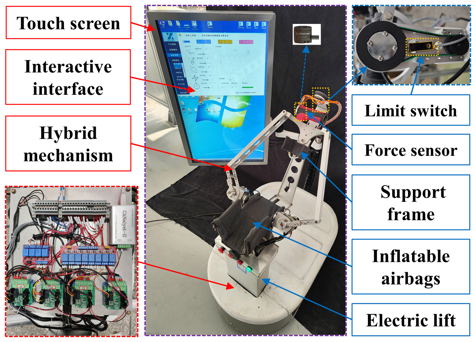
The elbow–wrist rehabilitation robot mainly consists of a series-parallel hybrid mechanism R(2-URR/RRS)Pe, a lifting column, an electric control box, and a touch screen. Among them, Pe is an elastic prismatic pair driven by the human elbow joint, which is used to compensate for the axis error of the elbow joint. The adoption of the elastic prismatic pair and inflatable airbags improves the comfort of patients during active rehabilitation training. The structure of the elbow–wrist rehabilitation robot is shown in Fig. 1.
The human motion branch and the elbow–wrist rehabilitation robot form a human–robot closed-loop system, with the force at the end of the human arm measured by a 3D force sensor as the system input. Since the 3D force sensor cannot directly measure the torque information required for active rehabilitation of the elbow and wrist joints, it is necessary to convert the force information into torque information using the positional relationship between coordinate systems. The coordinate system of the elbow–wrist rehabilitation robot is shown in Fig. 2.
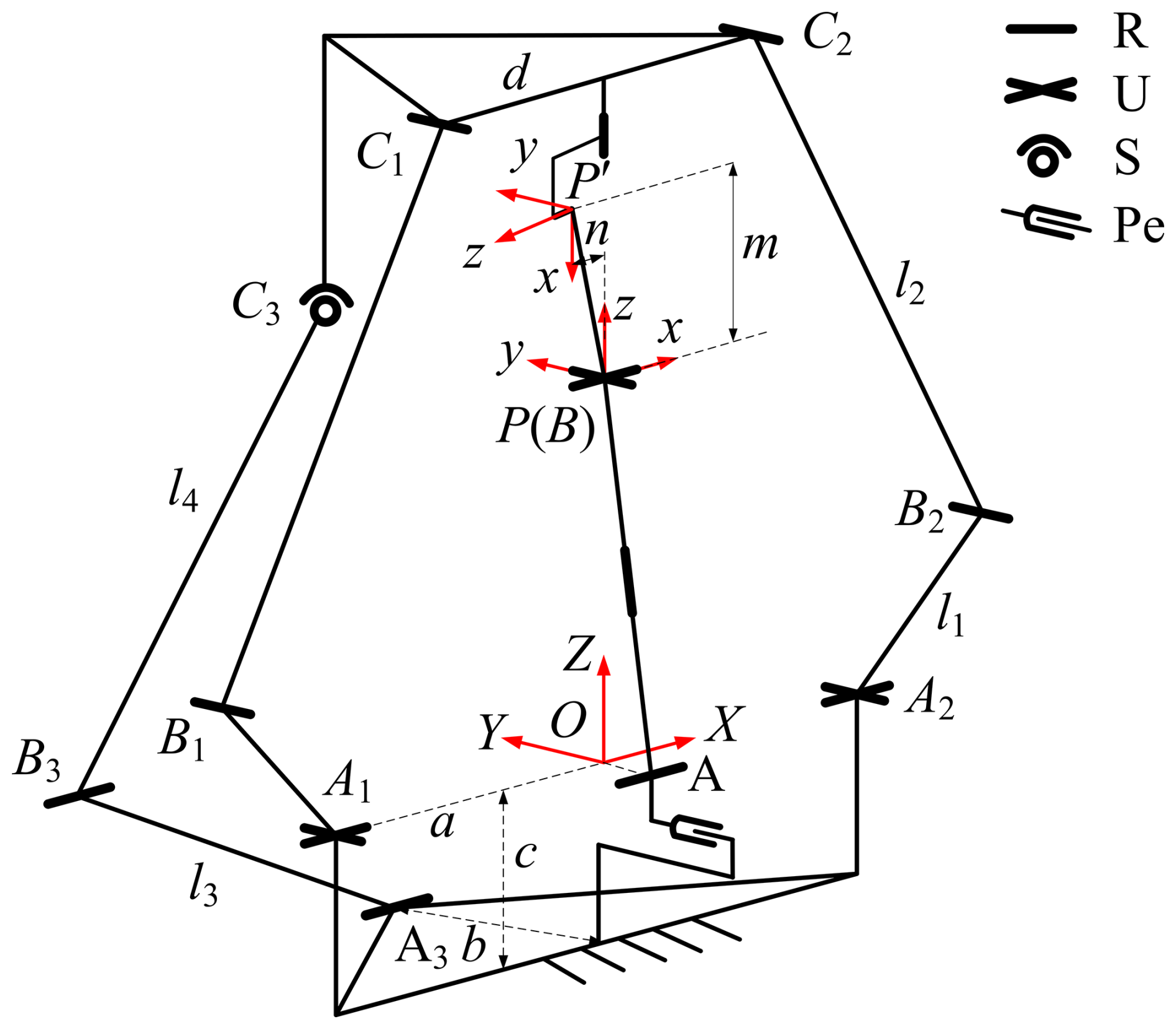
{O} and {P} are the fixed coordinate system and the moving coordinate system of the robot, respectively, and {P′} is the force sensor coordinate system. The moving platform of the mechanism can be described as follows in the fixed coordinate system:
The instantaneous pose of the moving platform can be expressed by the rotation matrix R:
Since P′ is the origin of the force sensor coordinate system, the force signal can be expressed as follows:
In the initial pose, when the force sensor rotates θ around the Z axis of the moving coordinate system, the rotation matrix can be expressed as follows:
At this time, the position of P′ in the moving coordinate system can be described as follows:
Given n=8 and m=75, the homogeneous coordinates of point M in the fixed coordinate system are as follows:
The homogeneous coordinates of point P′ in the fixed coordinate system are as follows:
Vector P′M can be expressed as follows:
In order to meet the safety principle, the speed and acceleration of the rehabilitation robot during the movement are small, and the influence of the mass distribution of the robot at different initial positions on the measured value of the force sensor can be compensated for by software. It is known that , , and so the torque of the space force on the X axis of the fixed coordinate system, that is, the elbow joint torque, is as follows:
The torque of the space force on the Y axis of the moving coordinate system, that is, the wrist joint torque, is as follows:
By solving the above torque, the expressions of Mx and My can be obtained as follows:
where α is the elbow joint angle; β is the wrist joint angle; γ is the radioulnar joint angle; and fx, fy, and fz are the components of the spatial force along the X-axis, Y-axis, and Z-axis directions of the force sensor coordinate system, respectively. Although the torque of the space force to the force sensor coordinate system is zero in theory, in the actual rehabilitation training, due to the offset of the force action point, the torque of the space force to the X axis of the force sensor coordinate system, that is, the radioulnar joint torque, is as follows:
2.2 Acquisition and processing of the sEMG signal
The motion patterns of the elbow and wrist joints are related to the state of the upper-limb muscles and are characterized by sEMG signals. The sEMG has poor robustness and is easily affected by the external environment. The interference factors in the acquisition process mainly include the following:
-
External environmental noise. This mainly refers to the electromagnetic (EMC) interference caused by electronic equipment, power supply, and wires to the sEMG signal acquisition equipment. The EMC interference will lead to a large distortion of the signal, and the system will not be able to operate normally. Therefore, the acquisition of sEMG signals should be carried out in a space without too many electronic devices and should ensure that the acquisition device is at least 1 m away from the electric control box of the elbow–wrist rehabilitation robot.
-
Muscle fatigue. The longer the signal acquisition time is, the deeper the fatigue of human muscles will be, and the amplitude of the sEMG signal will increase significantly. At this time, the sEMG signal cannot feed back the patient's real motion intention. During the actual operation, the signal acquisition time is not more than 5 min. If the time exceeds the specified time, the subject must take a short rest until the arm muscles are completely relaxed.
-
Resistance of the skin. Factors such as dry epidermal tissue, dense stratum corneum, and secretions on the surface of the skin increase the resistance of the skin. High resistance will make the amplifier circuit more sensitive to noise, which will cause the signal-to-noise ratio of the system to decrease and the random error to increase. The common method is to depilate and clean the skin in the signal acquisition area before pasting the electrode. In the process of signal acquisition, excessive sweat secretion will lead to increased skin impedance and even make the electrode fall off. Therefore, it is necessary to ensure that the subject carries out the experiment at a comfortable temperature.
-
Position of the electrode. During the movement of the subject, the electrode may produce a small displacement due to muscle contraction or stretching, resulting in a low-frequency drift of the sEMG signal. Therefore, when pasting the electrode, it is necessary to follow the direction of the muscle fibers and try to stay away from the joints with a large range of motion. In addition, the spacing of each acquisition position should be at least 3 cm in order to reduce the mutual interference between the signals and the friction between the wires. If the electrode loosens or even falls off directly during the signal acquisition process, it is necessary to immediately stop the experiment and replace the new electrode.
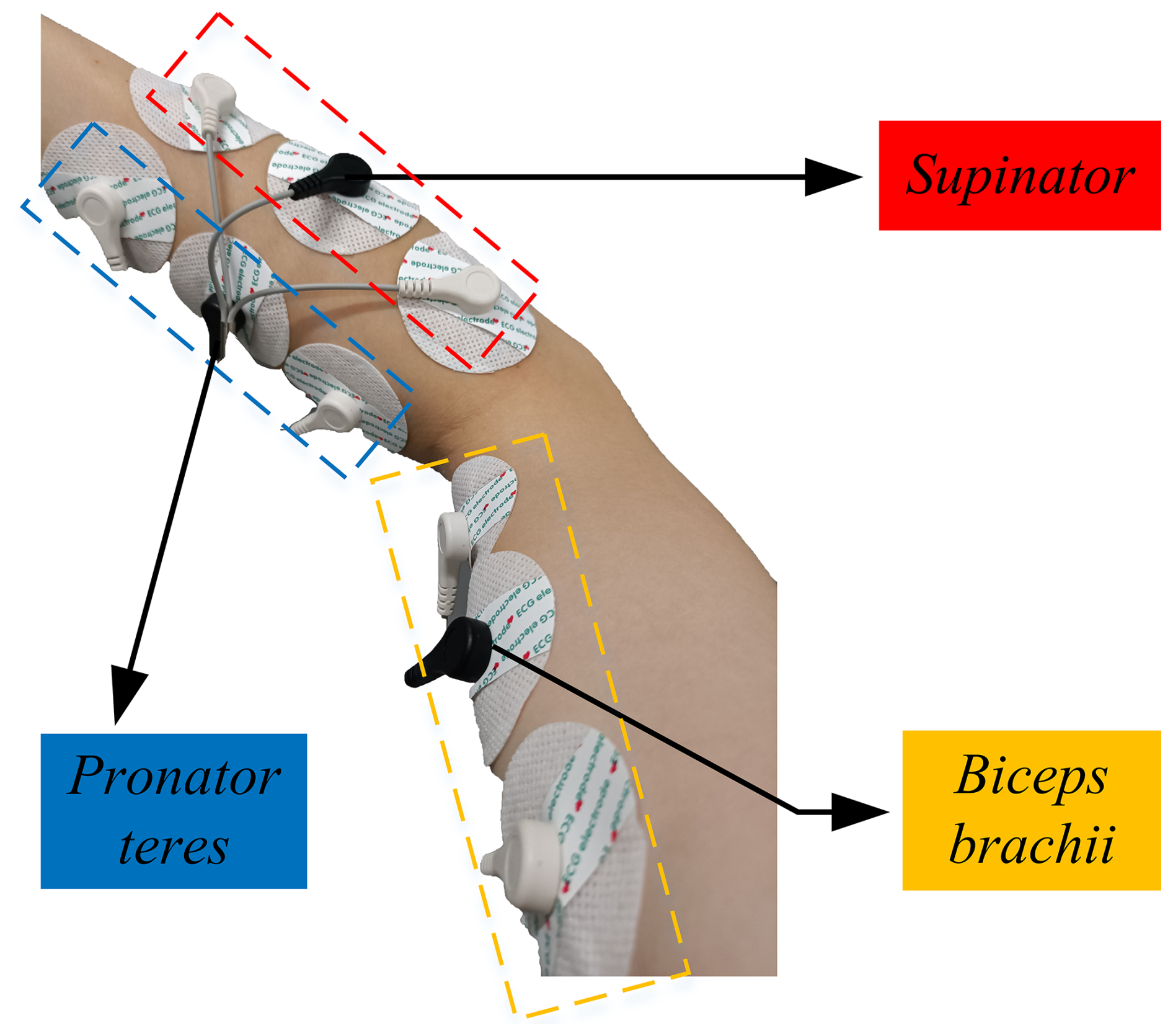
The structure of human upper-limb muscles is complex. Different muscle groups are composed of varying numbers of deep and superficial muscles. Since the number of channels supported by the acquisition system is limited and because an excessive number of signal acquisition positions is not conducive to motion decoupling and feature dimensionality reduction, targeted selection of signal acquisition positions is required. The selected muscles should avoid functional overlap as much as possible to ensure that the contribution of muscles to different movements is differentiated. Among the muscles associated with elbow and wrist movements, the biceps brachii, which can significantly characterize elbow joint motion, as well as the pronator teres and supinator muscles, which can significantly characterize radioulnar joint motion, are selected as the signal acquisition positions. The acquisition positions of the sEMG signals are shown in Fig. 3.
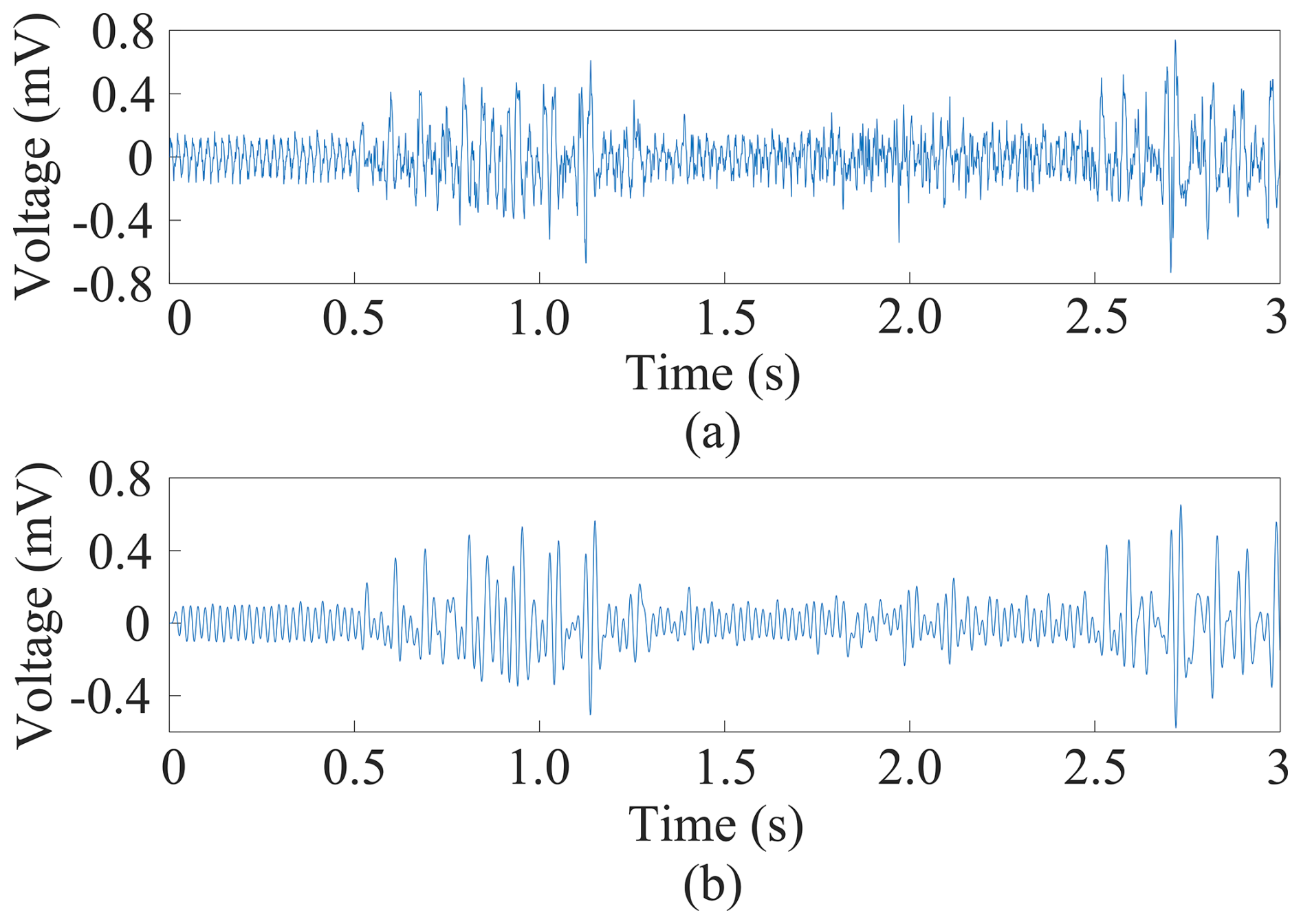
Because the sEMG signal has poor resistance to external interference, the original signal needs to be filtered before data fusion, as shown in Fig. 4. From the time domain characteristics, the filtered signal is more stable, and the amplitude is reduced (Li et al., 2021).
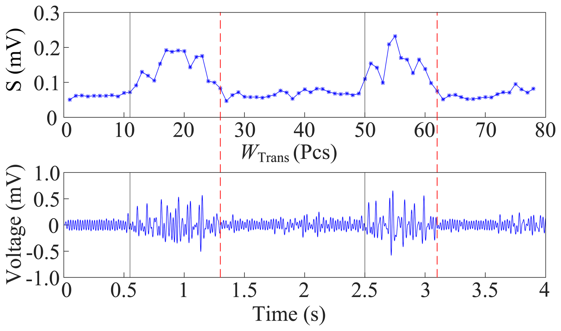
Active segment extraction is performed on the filtered signal. The purpose of active segment extraction is to distinguish whether the fluctuations of the sEMG signal correspond to effective human motion or interference under a resting state. The core of active segment extraction lies in determining the start and end points of movement. Based on the moving-average method, a flexible single-channel multi-threshold extraction algorithm is adopted for active segment extraction. The calculation equation of the moving average method is as follows:
where sEMGraw(i) represents the original signal amplitude of the single channel at time i, N is the number of data points, and H is the number of channels. Under the premise of a sampling frequency of 1000 Hz, the time window WTime of the moving-average method is set to 100 ms, and the moving window WTrans is set to 50 ms. Therefore, each time window will retain part of the information of the previous time window. Finally, the moving-average processing can be obtained:
The single-channel multi-threshold extraction algorithm is a delay decision algorithm that sacrifices some real-time performance to ensure data accuracy. Using this method to extract the active segment of the signal, the mean value of the moving window and the extraction result of the active segment are shown in Fig. 5.
2.3 Design of multi-source information fusion algorithm
A complete sEMG muscle force estimation framework is composed of two parts: feature extraction and muscle force model construction. The one-dimensional time series characterizing muscle activation state is taken as the input of the force estimation model. Muscle force models are generally divided into physiological models and pure mathematical models. The representative physiological model is the Hill model (Chen and Franklin, 2023), which calculates muscle force by combining the active force from muscle fibers and the passive force from tendons and corrects the active force considering individual muscle conditions. Due to the complex structure and difficult parameter determination of the Hill model, mathematical models are commonly adopted in practical applications. The selection criterion of mathematical models is to fit the function between muscle force and sEMG as much as possible to achieve the minimum force estimation error. In view of the high coupling of forearm muscles, this paper only conducts the force estimation of the biceps brachii. Typical models include the neural network model, polynomial model, power exponential model, and linear model (Wahid et al., 2024). The linear model has a simple calculation process but cannot accurately describe the actual relationship between sEMG and muscle force. In comparison, the polynomial model presents higher fitting degree with high efficiency and high precision. Hence, the polynomial model is selected for sEMG-based muscle force estimation (Zhang et al., 2019). The nonlinear relationship between sEMG signals and muscle force is described using a quadratic polynomial model:
where F is the estimated muscle force signals; x(i) refers to the sEMG signal; N is the length of the sEMG signal; RMS represents the root mean square of sEMG signals; and a0, a1, and a2 are regression coefficients identified by the least squares method. The estimated muscle force values are shown in Fig. 6.
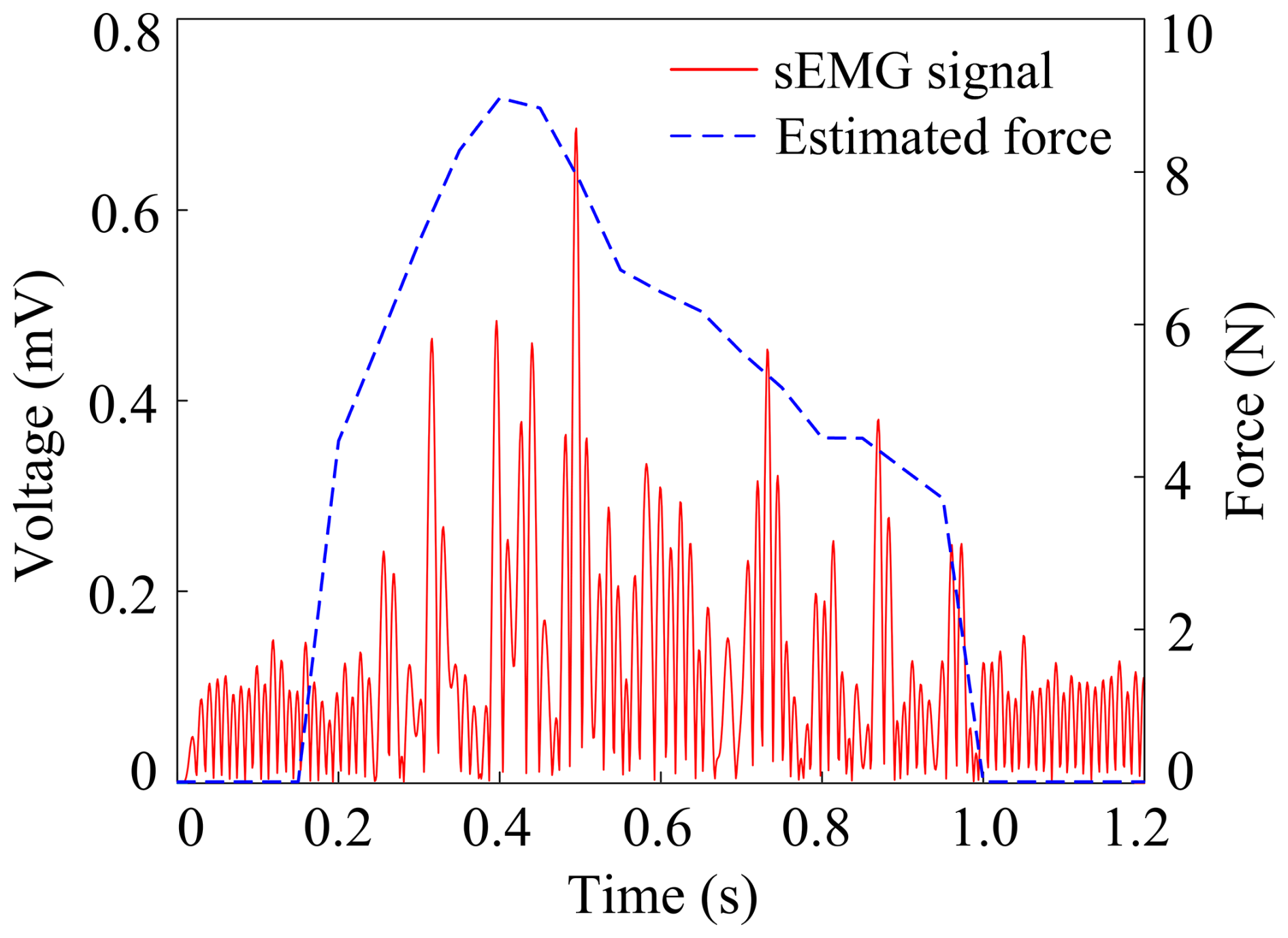
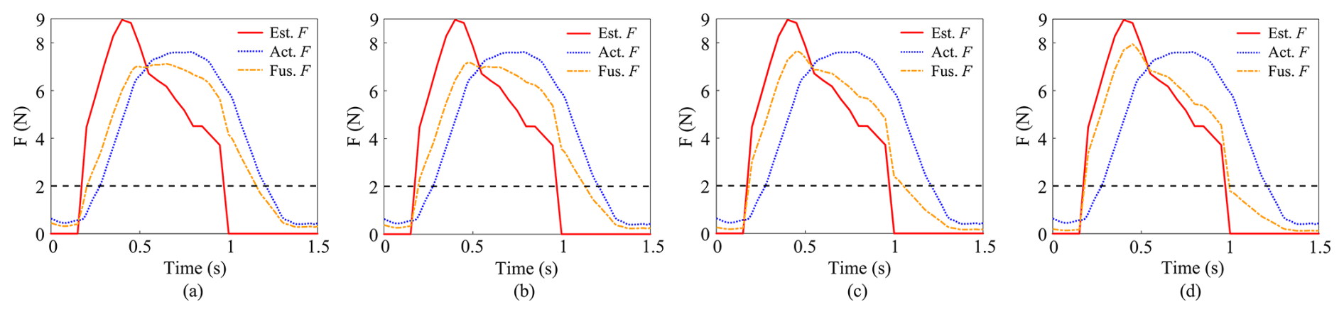
Figure 7Multi-source information fusion based on Kalman filter. (a) Kk=0.3; (b) Kk=0.4; (c) Kk=0.5; (d) Kk=0.6.
The estimated force signal in Fig. 6 exhibits large abrupt changes. If directly used as the input of the control system, it is difficult to achieve compliant control of the elbow–wrist rehabilitation robot. Although the estimated force signal is difficult to apply directly to the control of the elbow–wrist rehabilitation robot, its predictability of the patient's movement complements the accuracy of the actual force signal. This paper specifies that the fusion of the actual force signal and the estimated force signal is a linear process. Therefore, the Kalman filtering method is adopted for denoising and optimal estimation of the fused force signal. At time k, the system equation can be described as follows:
where xk is the current state of the system, yk is the measured value, A is the state transition matrix, B is the control matrix, Qk−1 is the system state noise, Rk is the measured noise, and uk−1 is the control quantity. The goal of the Kalman filter is to minimize the difference between the predicted value and the actual value. The update method of the system equation and the measurement equation is
where is the estimated value of the system state at time k, is the covariance matrix, and I is the unit matrix. The magnitude of Kalman gain Kk depends on Qk−1 and Rk. By adjusting Qk−1 and Rk, Kk converges to 0.3, 0.4, 0.5, and 0.6, respectively. The multi-source information fusion curve is shown in Fig. 7.
When the fused force signal is greater than 2N, the patient is determined to have motion intention, and the elbow–wrist rehabilitation robot starts to move. Conversely, when the fused force signal is less than 2N, the elbow–wrist rehabilitation robot stops moving. The results are analyzed using the values of the actual force signal corresponding to the start and end points of motion from the fused force signal and the motion duration as evaluation indicators, as shown in Table 1. It should be noted that the sEMG muscle force and six-dimensional force data in Fig. 7 are the average values collected from multiple experiments conducted on three healthy subjects. The variances of the estimated force signals and six-dimensional force signals of the three subjects are all within 15 %.
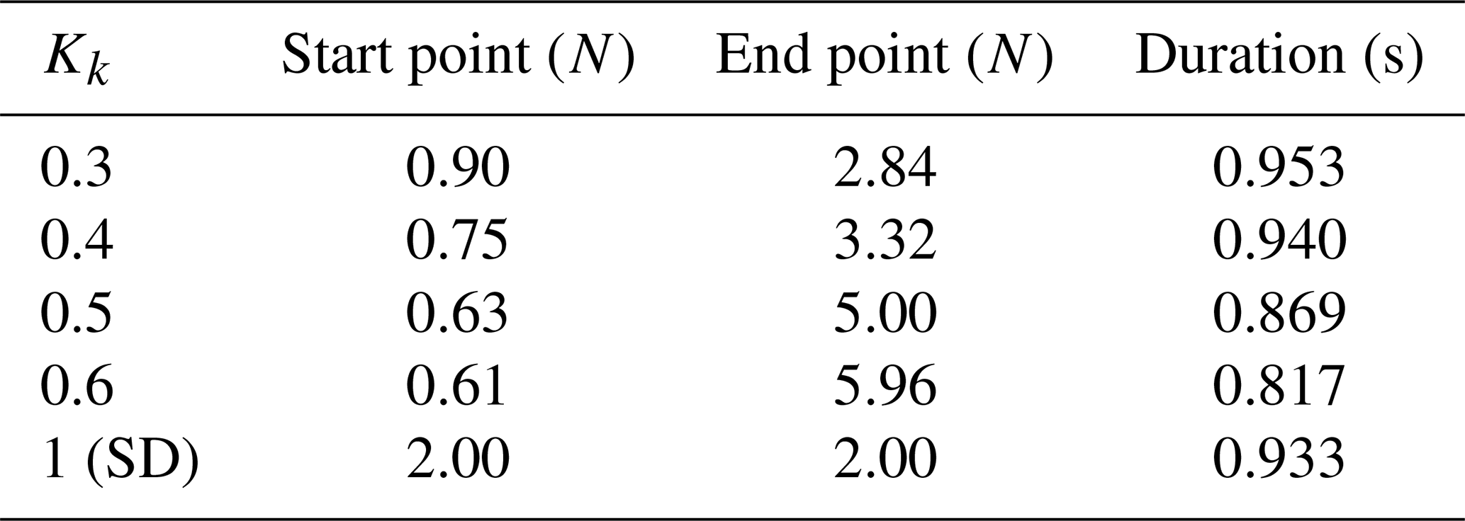
It can be seen from Table 1 that the force at the motion starting point has little difference, and an early response to motion can be achieved in all cases, whereas the force at the motion ending point varies greatly. When Kk is 0.3, the force at the motion starting point is relatively large, resulting in poor dynamic response of the system. When Kk is greater than 0.5, the force at the motion ending point is relatively large, and the patient will feel an impact at the end of the motion, which impairs the motion compliance. From the perspective of the motion duration of the elbow–wrist rehabilitation robot, the motion duration at Kk=0.4 is closer to the standard motion time. In summary, to balance the rapid response of the control system and force compliance, the fused force signal with a Kalman gain of 0.4 is selected as the input of the control system. The multi-source information fusion algorithm based on Kalman filtering uses the characteristics of human–robot interaction force signals and sEMG signals for motion intention recognition so as to predict the upper-limb motion of the patient.
3.1 Admittance control model
The compliance control strategy of the elbow–wrist rehabilitation robot enables patients with upper-limb motor disorders to actively participate in rehabilitation training on the premise of ensuring their safety, thereby improving the efficiency of treatment. However, recognizing the patient's motion intention using the fused force signal is only the first step of rehabilitation training. Next, the recognized motion intention needs to be transformed into motor motion through the control model. Since the elbow–wrist rehabilitation robot takes the fused force signal as the input of the control system, an admittance control model is adopted in this paper, in which the inner loop is a sliding-mode controller, as shown in Fig. 8.
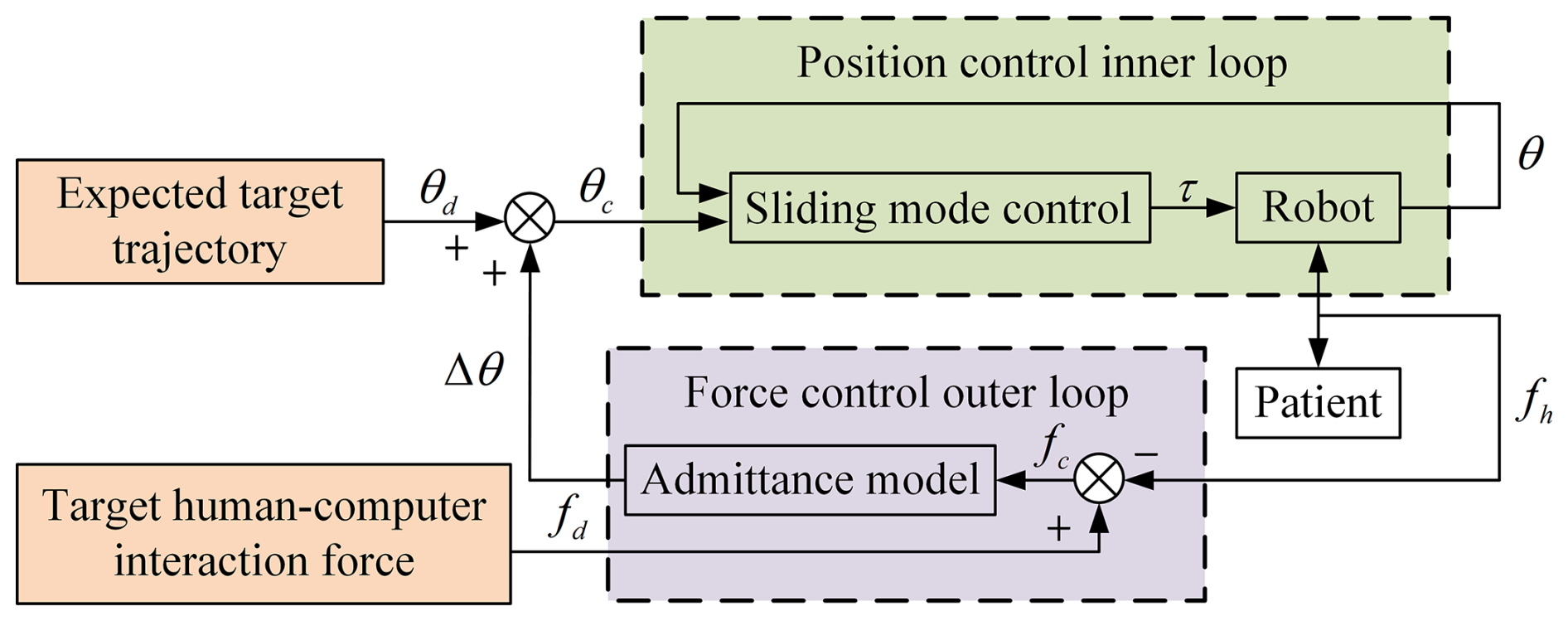
The essence of admittance control is to indirectly realize force control by modifying the angles of each joint of the robot, and its model reflects the mapping relationship between the fused force signal error and the displacement correction. However, the admittance principle cannot achieve target trajectory tracking, and so the sliding-mode controller is also required to track the displacement of the elbow–wrist rehabilitation robot. Compared with the conventional PD controller, the sliding-mode controller exhibits stronger robustness against external disturbance forces and dynamically varying nonlinear systems. Considering the problems of chattering and slow convergence speed in the sliding-mode reaching law, this paper designs a sliding-mode controller based on the double exponential reaching law, which suppresses chattering while ensuring the motion performance of the elbow–wrist rehabilitation robot. The reference variables and are defined as follows:
where is the expected value of the joint angular velocity, is the expected value of the joint angular acceleration, and Λ and Ω are the gain matrices. The parameter error matrix is defined as follows:
The combination of Eqs. (19) and (20) can be obtained:
Next, the sliding-mode switching function is defined as follows:
The control law can be designed as follows:
where τc is the compensation term used to compensate for the unmodeled dynamic changes and the overall disturbance of the system. The expression of the double exponential reaching law is defined as follows:
where K1, K2, and K3 are gain coefficients; α is the first exponential coefficient; and β is the second exponential coefficient. According to Eq. (24), τc can be expressed as follows:
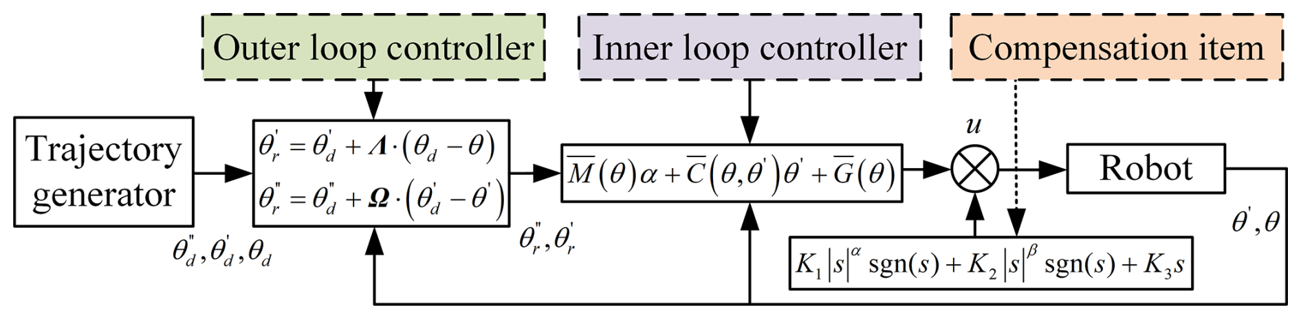
Figure 9 is the block diagram of the sliding-mode controller. The sliding-mode controller based on the double exponential reaching law achieves a good balance between chattering suppression and motion performance guarantee for the elbow–wrist rehabilitation robot.
3.2 Stability analysis of the controller
Based on the Lyapunov stability criterion, the stability of the compliance control system for the elbow–wrist rehabilitation robot is analyzed. First, the Lyapunov function is constructed as follows:
The derivative of Eq. (26) can be obtained:
Substituting Eq. (22) into Eq. (27) allows us to obtain the following:
The combination of Eqs. (23) and (28) can be obtained:
It can be seen from Eq. (29) that the model error and the compensation term τc will affect the stability of the system. Therefore, by combining Eqs. (25) and (29), the following can be obtained:
In Eq. (30), when , the value of s is 0. It can be concluded that s≡0 is the global equilibrium point that makes the system asymptotically stable, that is, the point at which the system will eventually converge to the global equilibrium point.
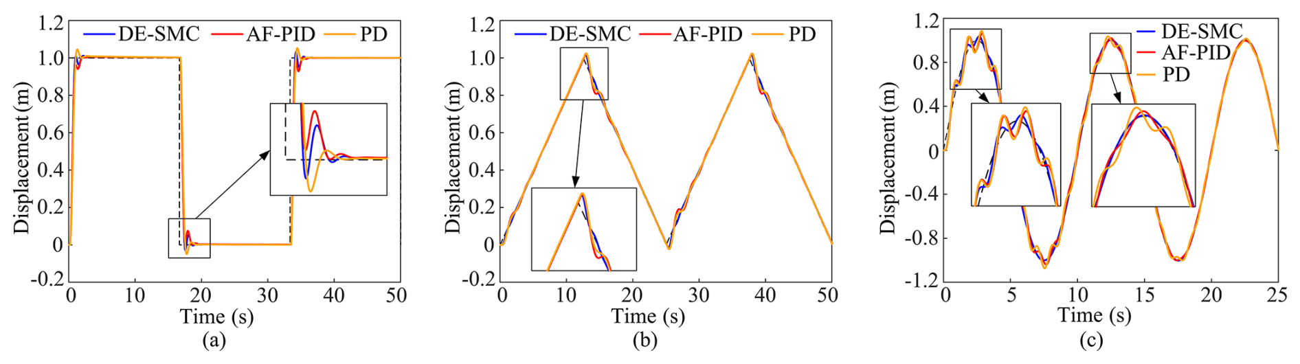
Figure 10Simulation curves. (a) Pulse signal input. (b) Triangular signal input. (c) Sinusoidal signal input.
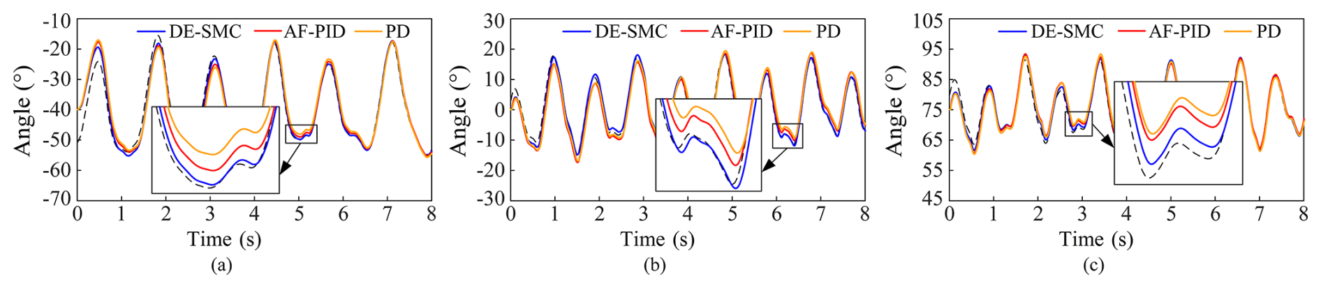
Figure 11Simulation curves of different joints. (a) Elbow joint; (b) wrist joint; (c) radioulnar joint.
3.3 Simulation of the control strategy
Simulink simulations are conducted to verify the trajectory-tracking performance of the sliding-mode controller with a double exponential reaching law (DE-SMC). Comparative analyses are performed with the PD controller and the IPSO-based adaptive fuzzy PID controller (AF-PID). Pulse signals, triangular signals, and standard sinusoidal signals are employed as system inputs for comparative tests. The corresponding simulation results are presented in Fig. 10.
The aforementioned simulations were conducted under ideal conditions with no external disturbances. Subsequently, the actual motion data of human elbow, wrist, and radioulnar joints are taken as the input of the control system. The tracking performance of the three controllers for the desired trajectory is presented in Fig. 11.
By analyzing the curves in Figs. 10 and 11, it can be found that the PD controller can track the desired trajectory but with unsatisfactory performance, which is mainly reflected in the large tracking error during the motion commutation stage. Although the adaptive fuzzy PID controller enables online parameter updating and improves system robustness, it suffers from poor real-time performance in parameter tuning, resulting in a control effect comparable to that of the PD controller. In contrast, the sliding-mode controller achieves superior trajectory-tracking performance with fast convergence speed and low tracking error, which conforms to the inherent characteristic of the high reaching rate of the sliding-mode control strategy. It can be concluded that the PID controller based on swarm optimization algorithms is suitable for large-delay and large-inertia systems with slowly time-varying parameters, while the sliding-mode controller is more applicable to strongly nonlinear systems with severe external disturbances and high real-time requirements.
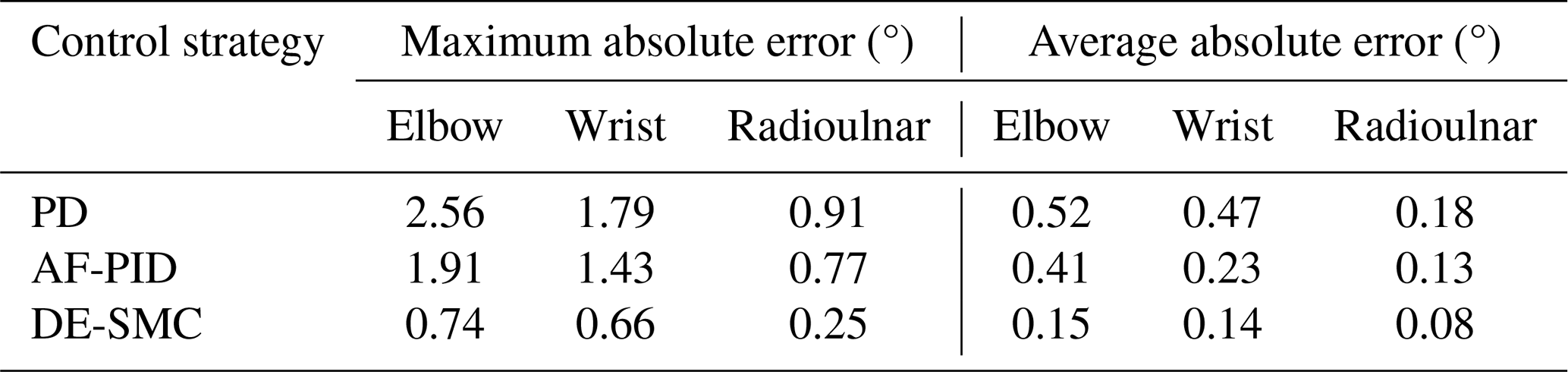
To quantitatively compare the trajectory-tracking performance among the PD controller, adaptive fuzzy PID controller, and sliding-mode controller based on the double exponential reaching law, the maximum absolute error and mean absolute error are selected as evaluation indicators. As shown in Table 2, the sliding-mode control delivers substantially better control performance than conventional PD control and exhibits stronger anti-disturbance capability than the adaptive fuzzy PID controller. In addition, the tracking errors of the elbow joint and wrist joint are higher than those of the radioulnar joint, indicating that external disturbance torques exert a more significant impact on the elbow and wrist joints, while having a limited effect on the radioulnar joint. In conclusion, the proposed sliding-mode controller with a double exponential reaching law possesses favorable tracking accuracy, high robustness, and superior anti-interference ability, which realizes precise tracking of motion trajectories.
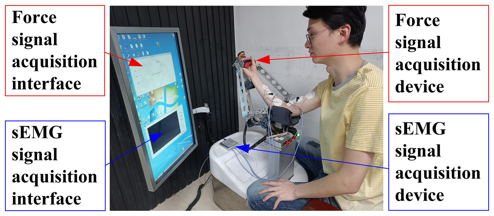
4.1 The force and sEMG signal fusion experiment
To verify the feasibility of the force and sEMG signal fusion algorithm, experiments were conducted. Since both the multi-source information fusion algorithm and the compliance control strategy proposed in this paper are at the stage of feasibility verification and to avoid secondary injury to patients with upper-limb motor disorders, all subjects in the experiments are healthy adults who have not received any rehabilitation training. The upper-arm length of the subjects in the force and sEMG fusion experiment is 34 cm, the forearm length is 27 cm, and the hand length is 19.6 cm. The precautions and experimental procedures are as follows:
-
The experiment was conducted in a space with a flat floor and free from interference from other electronic equipment. An assistant was present near the subject to prevent accidents. To further reduce external environmental interference on sEMG signals and to ensure data accuracy, hair removal and alcohol cleaning were performed on the skin at electrode attachment sites before the experiment. Electrodes could be attached only after the skin was completely dry. If electrodes shifted or fell off during the experiment, data acquisition was restarted with new electrodes (Xu and Xiong, 2021). In addition, the room temperature was maintained within 20 to 25° to avoid sudden changes in electrode impedance caused by temperature and sweating, which may interfere with sEMG signal acquisition.
-
On the premise of meeting the above experimental requirements, the prototype of the elbow–wrist rehabilitation robot was debugged, particularly to ensure that all functions of the ZJE-II signal acquisition system worked normally. The initial posture of the robot was adjusted to make the subject feel comfortable. Then the subject held the handle of the robot moving platform in a sitting position, and, finally, the inflatable airbag was adjusted to fix the forearm. The use of the inflatable airbag improved the comfort of rehabilitation training and also provided a protective effect.
-
The force–sEMG signal fusion program was run. The subject pulled the elbow–wrist rehabilitation robot in a pulse force mode, with a force cycle of approximately 1 s. To reduce the influence of muscle fatigue caused by prolonged movement on sEMG signals, the subject is required to rest for at least 1 min after every 10 cycles. During the experiment, the subject's elbow joint moves from the initial −80 to −45°, as shown in Fig. 12. After the experiment, the collected actual force curve and the calculated fused force curve are plotted, as shown in Fig. 13.
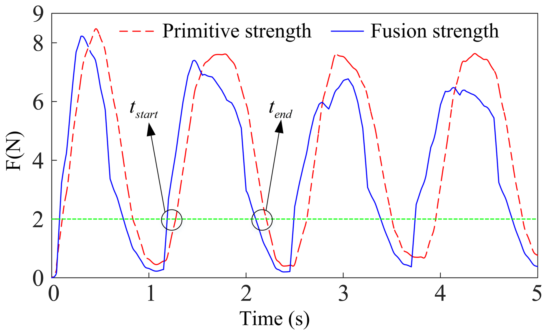
In Fig. 13, the red curve represents the subject's actual force signal, and the blue curve represents the fused force signal processed by the fusion algorithm. It can be seen that the fused force signal achieves a faster response time on the basis of retaining the high stability and linearity of the actual force signal, realizing the advance perception of movement. The equation for calculating the average lead time ta is defined as follows:
where tstart is the lead time at the start of movement, and tend is the lead time at the end of movement. The calculation results show that the fused force signal can predict the subject's motion intention 102.5 ms in advance. Therefore, taking the fused force signal as the input of the admittance control system achieves the unity of rapid response and force compliance of the control system.
4.2 Compliance control experiment
The DOF of human motion involved in the compliance control strategy experiment include flexion and extension of the elbow joint, adduction and abduction of the wrist joint, and internal rotation and external rotation of the radioulnar joint. Before the experiment, the mechanical limit and electrical limit of the elbow–wrist rehabilitation robot should be ensured to work normally to guarantee the safety of the subjects. Then, the initial posture of the elbow–wrist rehabilitation robot and the inflatable airbag were adjusted to make the subjects feel comfortable. Finally, active rehabilitation training of the elbow joint, wrist joint, and radioulnar joint was carried out on three healthy adult males without any previous rehabilitation training, as shown in Fig. 14. After the experiment, the measured human–robot interaction force and the motion angle of the servo motor were plotted as curves, as shown in Fig. 15.
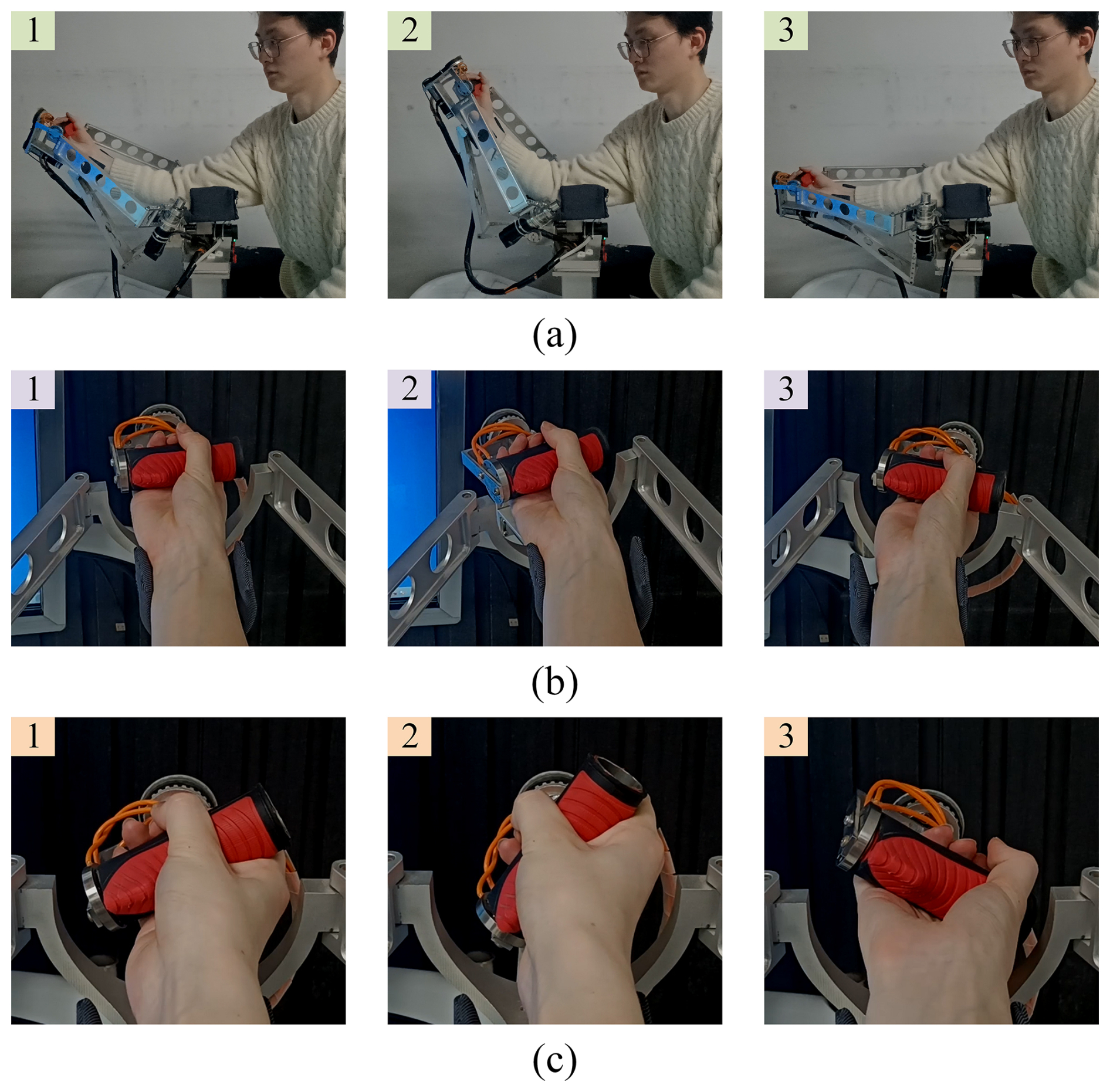
Figure 14Compliance control experiment. (a) Elbow joint; (b) wrist joint; (c) radioulnar joint.
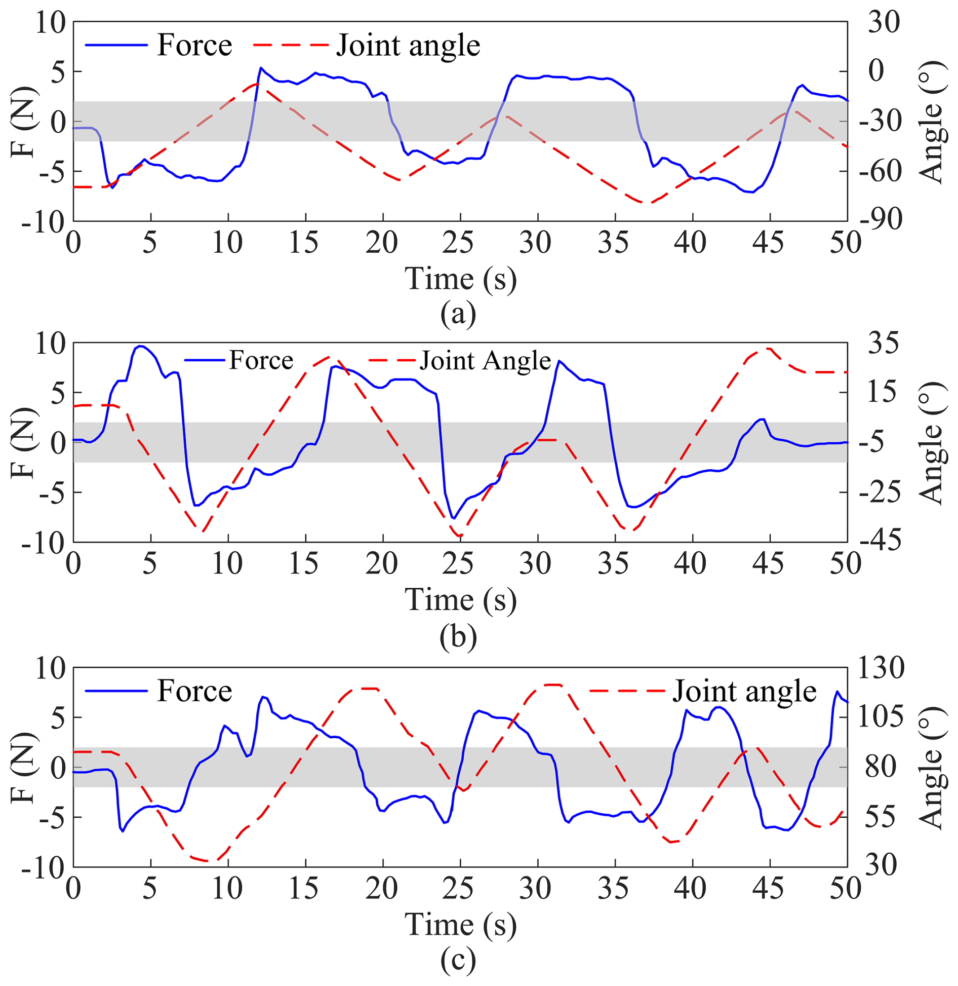
Figure 15Force–position curve of compliance control. (a) Elbow joint; (b) wrist joint; (c) radioulnar joint.
The gray region in Fig. 15 denotes the motion transition zone. When the blue human–robot interaction force curve passes through the gray region, the motion direction of the elbow–wrist rehabilitation robot changes. The force threshold corresponding to the gray region is 2N. When the absolute value of the human–robot interaction force exceeds 2N, the system recognizes that the subject has a motion intention, and the elbow–wrist rehabilitation robot starts to move. Otherwise, it remains stationary.
The compliance coefficient can quantify the robot's ability to accommodate human voluntary movement, which is essential for reducing the risk of sports injury and improving the comfort of rehabilitation training. It is generally defined as the ratio of displacement or joint angle to human–robot interaction force and is primarily adopted in constant compliance control with fixed stiffness and damping parameters during passive rehabilitation training (Liu et al., 2017). Nevertheless, the constant parameter mode fails to adapt to individual differences in motor ability and muscle tone among patients, resulting in poor versatility. Accordingly, current research gradually focuses on adaptive compliance regulation technology, which realizes the real-time dynamic adjustment of the compliance coefficient by fusing interaction force, sEMG signals, and motion data (Tian et al., 2022). Inspired by the above studies, especially the research conducted by Hu et al. (2023), this paper proposes a novel compliance coefficient based on the time delay characteristics of human–robot collaborative motion. The time delays of the elbow–wrist rehabilitation robot in forward and reverse motions are defined as tpos and tneg, respectively, as shown in Fig. 16.
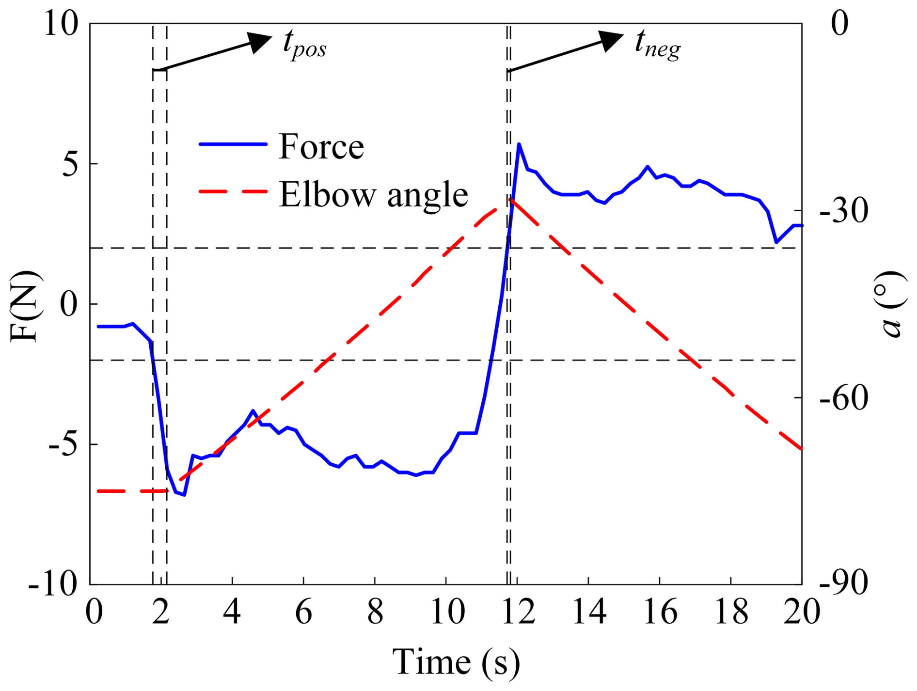
To quantitatively characterize the influence of time delay on the compliance control strategy of the elbow–wrist rehabilitation robot, the compliance coefficient of the control system is defined as follows:
The reference value of the compliance coefficient is determined when the system only takes six-dimensional force signals as input and adopts a non-adaptive PD controller. Under this constraint, repeated experiments show that the robot motion response delay treact is 400 ms. The average of forward delay tpos and reverse delay tneg is equal to treact, and the reference compliance coefficient is calculated as 1. In Eq. (32), λ is inversely proportional to human–robot interaction delay. A smaller λ leads to longer motion response lag and poorer system compliance. Patients will perceive obvious resistance during rehabilitation training, and excessive system damping may cause secondary injuries to upper limbs.
It should be noted that the compliance control experiment in Fig. 14 takes fused force signals as system input and applies the proposed DE-SMC controller. To verify its performance, testers and experimental procedures are kept consistent, and only different controllers are adopted. The compliance coefficients of elbow, wrist, and radioulnar joints under three control strategies are obtained, as shown in Table 3.
Table 3Compliance coefficients under different control strategies.
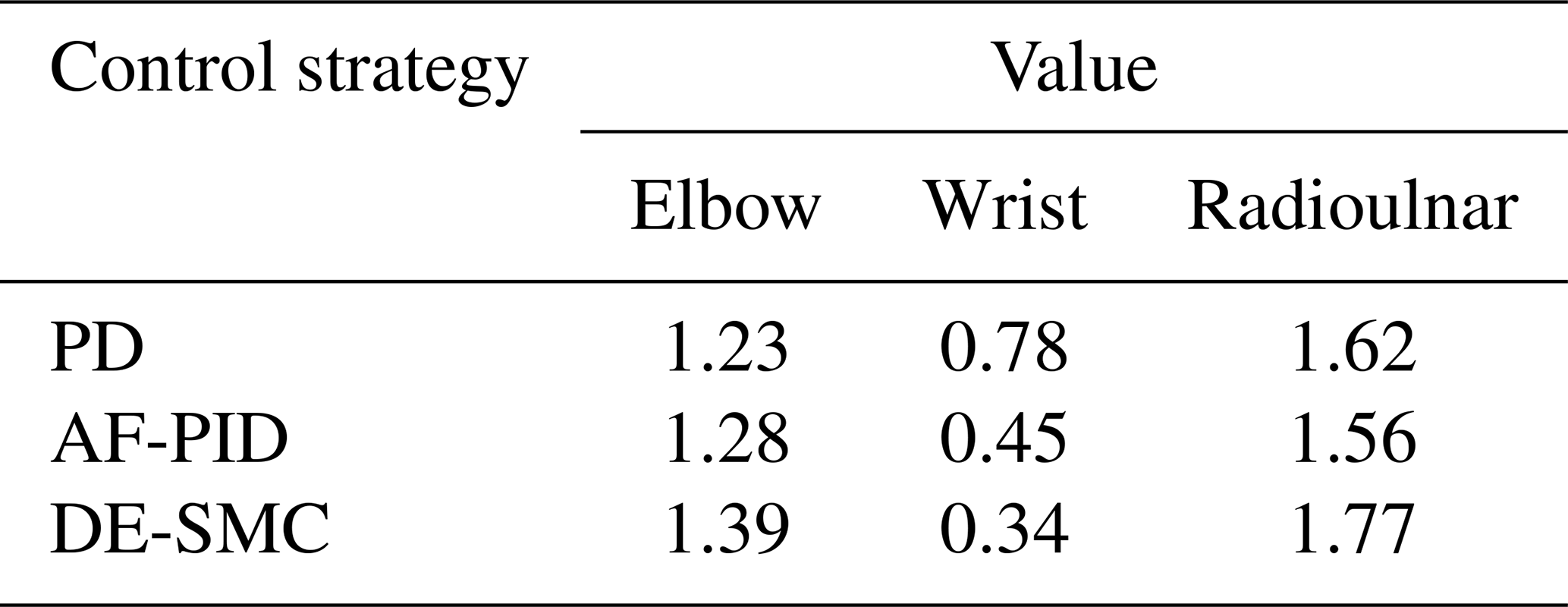
As shown in Table 3, the system compliance of the robot adopting the DE-SMC strategy is slightly higher than that of the AF-PID and PD controllers, while no significant difference is observed between the latter two. By comparing the compliance coefficients of each joint, it can be found that the elbow joint and radioulnar joint present higher compliance, whereas the wrist joint exhibits relatively low compliance. Accordingly, the motion response lag of the wrist joint is relatively longer.
To meet the needs of patients with upper-limb motor disorders to allow them to actively participate in rehabilitation training, this paper proposes a compliance control strategy for an elbow–wrist rehabilitation robot based on multi-source information fusion. Based on filtering and active segment extraction of sEMG signals, the estimated force signal and the actual force signal are fused using Kalman filtering. The fused force signal with a Kalman gain of 0.4 is selected as the input of the control system, achieving the unity of rapid motion response and force compliance. To further improve the trajectory-tracking performance of the control system, a sliding-mode controller based on the double exponential reaching law is designed, and the stability of the system is verified using the Lyapunov criterion. By comparing the tracking performance with the traditional PD controller, it is proved that the sliding-mode controller based on the double exponential reaching law has high tracking accuracy and strong anti-interference ability. Finally, the force and sEMG fusion experiment and the compliance control experiment were carried out. The former showed that the fused force signal can predict the subject's motion intention 102.5 ms in advance, while the latter confirmed that the subject's elbow joint and radioulnar joint had high motion compliance, whereas the wrist joint had relatively low compliance.
According to the experimental results, the overall compliance of the wrist joint is relatively low during the training process with the elbow–wrist rehabilitation robot. Therefore, the internal mechanism behind this phenomenon will be prioritized for analysis in future research. Meanwhile, considering the fact that human–robot interaction force signals exhibit significant random fluctuations in practical clinical environments, the research team will develop a variable damping admittance controller. This scheme can suppress the instantaneous drastic acceleration of the control system caused by sudden force signal changes, thereby effectively avoiding the risk of secondary injury to patients with upper-limb motor disorders during rehabilitation training.
The code and data of this paper are available on request. Please contact the corresponding author.
HB contributed to the conception and funding acquisition. HS and ZL performed the theoretical analysis. YX conducted the experiments and drafted the original paper. PD and MW provided support for the algorithm design. RL and ZL organized the conclusions and were responsible for project coordination.
The contact author has declared that none of the authors has any competing interests.
Publisher's note: Copernicus Publications remains neutral with regard to jurisdictional claims made in the text, published maps, institutional affiliations, or any other geographical representation in this paper. The authors bear the ultimate responsibility for providing appropriate place names. Views expressed in the text are those of the authors and do not necessarily reflect the views of the publisher.
We sincerely appreciate the valuable contributions from the editor, Pengyuan Zhao, and the reviewers.
This research was supported by the National Natural Science Foundation of China Project (grant no. 51305380).
This paper was edited by Pengyuan Zhao and reviewed by two anonymous referees.
Abbas, M., Narayan, J., and Dwivedy, S. K.: Event-triggered adaptive control for upper-extremity therapeutic robot in active-assist mode: A simulation study, P. I. Mech. Eng.-C J. Mec., 238, 4628–4643, https://doi.org/10.1177/09544062231208722, 2023.
Antuvan, C. W., Bisio, F., Marini, F., Yen, S. C., Cambria, E., and Masia, L.: Role of Muscle Synergies in Real-Time Classification of Upper Limb Motions using Extreme Learning Machines, J. NeuroEng. Rehabil., 13, 15, https://doi.org/10.1186/s12984-016-0183-0, 2016.
Ao, X. H., Wang, F., Zhao, J., and She, J. H.: Interpretable analysis of feature importance and implicit correlation based on sEMG grayscale images, IEEE 6th International Conference on Industrial Cyber-Physical Systems (ICPS), Wuhan, PEOPLES R CHINA, 8–11 May, WOS:001031560600017, https://doi.org/10.1109/icps58381.2023.10128002, 2023.
Ayas, M. S. and Altas, I. H.: Fuzzy logic based adaptive admittance control of a redundantly actuated ankle rehabilitation robot, Control Eng. Pract., 59, 44–54, https://doi.org/10.1016/j.conengprac.2016.11.015, 2017.
Bao, T. Z., Xie, S. Q., Yang, P. F., Zhou, P., and Zhang, Z. Q.: Toward Robust, Adaptiveand Reliable Upper-Limb Motion Estimation Using Machine Learning and Deep Learning-A Survey in Myoelectric Control, IEEE J. Biomed. Health Inform., 26, 3822–3835, https://doi.org/10.1109/jbhi.2022.3159792, 2022.
Cai, S. Q., Chen, Y., Huang, S. Y., Wu, Y., Zheng, H. Q., Li, X., and Xie, L. H.: SVM-Based Classification of sEMG Signals for Upper-Limb Self-Rehabilitation Training, Front. Neurorobotics, 13, https://doi.org/10.3389/fnbot.2019.00031, 2019.
Cesqui, B., Tropea, P., Micera, S., and Krebs, H. I.: EMG-based pattern recognition approach in post stroke robot-aided rehabilitation: a feasibility study, J. NeuroEng. Rehabil., 10, https://doi.org/10.1186/1743-0003-10-75, 2013.
Chen, Z. Y. and Franklin, D. W.: Musculotendon Parameters in Lower Limb Models: Simplifications, Uncertainties, and Muscle Force Estimation Sensitivity, Ann. Biomed. Eng., 51, 1147–1164, https://doi.org/10.1007/s10439-023-03166-5, 2023.
Culmer, P. R., Jackson, A. E., Makower, S., Richardson, R., Cozens, J. A., Levesley, M. C., and Bhakta, B. B.: A Control Strategy for Upper Limb Robotic Rehabilitation With a Dual Robot System, IEEE/ASME Transactions on Mechatronics, 15, 575–585, https://doi.org/10.1109/TMECH.2009.2030796, 2010.
Duret, C., Hutin, E., Lehenaff, L., and Gracies, J. M.: Do all sub acute stroke patients benefit from robot-assisted therapy? A retrospective study, Restor. Neurol. Neuros., 33, 57–65, https://doi.org/10.3233/rnn-140418, 2015.
Horiuchi, Y., Kishi, T., Gonzalez, J., and Yu, W. W.: A Study on Classification of Upper Limb Motions from Around-Shoulder Muscle Activities, 11th IEEE International Conference on Rehabilitation Robotics, Kyoto, JAPAN, 23–26 June, WOS:000277086500051, 361–365, https://doi.org/10.1109/ICORR.2009.5209477, 2009.
Hu, B. S., Liu, F. C., Cheng, K., Chen, W. M., Shan, X. Y., and Yu, H. L.: Stiffness Optimal Modulation of a Variable Stiffness Energy Storage Hip Exoskeleton and Experiments on Its Assistance Effect, IEEE T. Neur. Sys. Reh., 31, 1045–1055, https://doi.org/10.1109/tnsre.2023.3236256, 2023.
Huo, W. G., Huang, J., Wang, Y. J., Wu, J., and Cheng, L.: Control of Upper-Limb Power-Assist Exoskeleton Based on Motion Intention Recognition, IEEE International Conference on Robotics and Automation (ICRA), Shanghai, PEOPLES R CHINA, 9–13 May, WOS:000324383401072, 2243–2248, https://doi.org/10.1109/ICRA.2011.5980483, 2011.
Li, J. C., Liang, T., Zeng, Z. N., Xu, P. P., Chen, Y., Guo, Z. Q., Liang, Z. H., and Xie, L. H.: Motion intention prediction of upper limb in stroke survivors using sEMG signal and attention mechanism, Biomed. Signal Proces., 78, https://doi.org/10.1016/j.bspc.2022.103981, 2022.
Li, X. X., Tian, L., Zheng, Y., Samuel, O. W., Fang, P., Wang, L., and Li, G. L.: A new strategy based on feature filtering technique for improving the real-time control performance of myoelectric prostheses, Biomed. Signal Proces., 70, https://doi.org/10.1016/j.bspc.2021.102969, 2021.
Little, K., Pappachan, B. K., Yang, S. B., Noronha, B., Campolo, D., and Accoto, D.: Elbow Motion Trajectory Prediction Using a Multi-Modal Wearable System: A Comparative Analysis of Machine Learning Techniques, Sensors, 21, https://doi.org/10.3390/s21020498, 2021.
Liu, Q., Liu, A. M., Meng, W., Ai, Q. S., and Xie, S. Q.: Hierarchical Compliance Control of a Soft Ankle Rehabilitation Robot Actuated by Pneumatic Muscles, Front. Neurorobotics, 11, https://doi.org/10.3389/fnbot.2017.00064, 2017.
Luo, S., Meng, Q., Li, S., and Yu, H.: Research of intent recognition in rehabilitation robots: a systematic review, Disability and Rehabilitation: Assistive Technology, 19, 1307–1318, https://doi.org/10.1080/17483107.2023.2170477, 2024.
Ruiz-Olaya, A. F., López-Delis, A., and Cerquera, A.: Toward an Upper-Limb Neurorehabilitation Platform Based on FES-Assisted Bilateral Movement: Decoding User's Intentionality, International Work-Conference on the Interplay Between Natural and Artificial Computation (IWINAC), Elche, SPAIN, 1–5 June, WOS:000363263300015, 143–152, https://doi.org/10.1007/978-3-319-18914-7_15, 2015.
Saglia, J. A., Tsagarakis, N. G., Dai, J. S., and Caldwell, D. G.: Control Strategies for Patient-Assisted Training Using the Ankle Rehabilitation Robot (ARBOT), IEEE/ASME Transactions on Mechatronics, 18, 1799–1808, https://doi.org/10.1109/TMECH.2012.2214228, 2013.
Sharkawy, A.-N. and Koustoumpardis, P. N.: Human–Robot Interaction: A Review and Analysis on Variable Admittance Control, Safety, and Perspectives, https://doi.org/10.3390/machines10070591, 2022.
Shi, M., Yang, C. Y., and Zhang, D. L.: A Novel Human-Machine Collaboration Model of an Ankle Joint Rehabilitation Robot Driven by EEG Signals, Math. Probl. Eng., 8, https://doi.org/10.1155/2021/5564235, 2021.
Soma, H., Horiuchi, Y., Gonzalez, J., and Yu, W. W.: Preliminary Results of Online Classification of Upper Limb Motions from Around-Shoulder Muscle Activities, IEEE International Conference on Rehabilitation Robotics (ICORR)/International Neurorehabilitation Symposium (INRS)/International Conference on Virtual Rehabilitation (ICVR), ETH Zurich, Zurich, SWITZERLAND, 27 June–1 Jul, WOS:000299169800033, https://doi.org/10.1109/ICORR.2011.5975368, 2011.
Song, G. K., Huang, R., Guo, Y. Z., Qiu, J., and Cheng, H.: An EEG-EMG-Based Motor Intention Recognition for Walking Assistive Exoskeletons, 15th International Conference on Intelligent Robotics and Applications (ICIRA) – Smart Robotics for Society, Harbin, PEOPLES R CHINA, 1–3 August, WOS:000870504300071, 769–781, https://doi.org/10.1007/978-3-031-13844-7_71, 2022.
Stefanou, T., Turton, A., Lenz, A., and Dogramadzi, S.: Upper Limb Motion Intent Recognition Using Tactile Sensing, IEEE/RSJ International Conference on Intelligent Robots and Systems (IROS)/Workshop on Machine Learning Methods for High-Level Cognitive Capabilities in Robotics, Vancouver, CANADA, 24–28 September, WOS:000426978206024, 6601–6608, https://doi.org/10.1109/IROS.2017.8206573, 2017.
Sun, J., Shen, Y., and Rosen, J.: Sensor Reduction, Estimation, and Control of an Upper-Limb Exoskeleton, IEEE Robot. Autom. Lett., 6, 1012–1019, https://doi.org/10.1109/LRA.2021.3056366, 2021.
Tang, Z. C., Zhang, L. T., Chen, X., Ying, J. C., Wang, X. Y., and Wang, H.: Wearable Supernumerary Robotic Limb System Using a Hybrid Control Approach Based on Motor Imagery and Object Detection, IEEE T. Neur. Sys. Reh., 30, 1298–1309, https://doi.org/10.1109/tnsre.2022.3172974, 2022.
Tian, J. J., Wang, H. B., Zheng, S. Y., Ning, Y. S., Zhang, X. C., Niu, J. Y., and Vladareanu, L.: sEMG-Based Gain-Tuned Compliance Control for the Lower Limb Rehabilitation Robot during Passive Training, Sensors, 22, https://doi.org/10.3390/s22207890, 2022.
Tucker, M. R., Olivier, J., Pagel, A., Bleuler, H., Bouri, M., Lambercy, O., Millán, J. d. R., Riener, R., Vallery, H., and Gassert, R.: Control strategies for active lower extremity prosthetics and orthotics: a review, J. Neuroeng. Rehabil., 12, https://doi.org/10.1186/1743-0003-12-1, 2015.
Wahid, A., Ullah, K., Ullah, S. I., Amin, M., Almutairi, S., and Abohashrh, M.: sEMG-Based Upper Limb Elbow Force Estimation Using CNN, CNN-LSTM, and CNN-GRU Models, IEEE Access, 12, 128979–128991, https://doi.org/10.1109/access.2024.3451209, 2024.
Wolbrecht, E. T., Chan, V., Reinkensmeyer, D. J., and Bobrow, J. E.: Optimizing Compliant, Model-Based Robotic Assistance to Promote Neurorehabilitation, IEEE T. Neur. Sys. Reh., 16, 286–297, https://doi.org/10.1109/TNSRE.2008.918389, 2008.
Wu, Q., Wang, X., Chen, B., and Wu, H.: Development of a Minimal-Intervention-Based Admittance Control Strategy for Upper Extremity Rehabilitation Exoskeleton, IEEE T. Syst. Man Cy. A, 48, 1005–1016, https://doi.org/10.1109/TSMC.2017.2771227, 2018.
Wu, Q. C. and Chen, Y.: Development of an Intention-Based Adaptive Neural Cooperative Control Strategy for Upper-Limb Robotic Rehabilitation, IEEE Robot. Autom. Lett., 6, 335–342, https://doi.org/10.1109/lra.2020.3043197, 2021.
Xie, C., Yang, Q., Huang, Y., Su, S. W., Xu, T., and Song, R.: A Hybrid Arm-Hand Rehabilitation Robot With EMG-Based Admittance Controller, IEEE T. Biomed. Circ. S., 15, 1332–1342, https://doi.org/10.1109/TBCAS.2021.3130090, 2021.
Xu, H. and Xiong, A.: Advances and Disturbances in sEMG-Based Intentions and Movements Recognition: A Review, IEEE Sens. J., 21, 13019–13028, https://doi.org/10.1109/JSEN.2021.3068521, 2021.
Zhang, C., Chen, X., and Zhang, X.: Heterogeneity Counts More than Power for HD-sEMG-Based Joint Force Estimation, 41st Annual International Conference of the IEEE Engineering in Medicine and Biology Society (EMBC), Berlin, GERMANY, 23–27 July, WOS:000557295302080, 1926–1929, https://doi.org/10.1109/embc.2019.8857227, 2019.
Zhang, P. F., Gao, X. S., Miao, M. D., and Zhao, P.: Design and Control of a Lower Limb Rehabilitation Robot Based on Human Motion Intention Recognition with Multi-Source Sensor Information, Machines, 10, https://doi.org/10.3390/machines10121125, 2022.