the Creative Commons Attribution 4.0 License.
the Creative Commons Attribution 4.0 License.
 | 29 May 2026
Design and kinematic analysis of a Miura-oriented origami continuum space manipulator with deployable bending capability
Ruiwei Liu
Manjia Su
Jinhui Zhou
Mengyu Zhong
Kengyi Wang
Hongwei Guo
Chunlong Wang
Haoyu Yang
The capture of irregular, dimension-variable non-cooperative space debris remains a critical challenge for on-orbit servicing. This paper proposes a continuum gripper based on modified right-angle Miura-ori tessellation, integrating deployable folding and controllable large-range bending. Geometric relations of crease parameters are derived to build a parametric model mapping two-dimensional fold patterns to three-dimensional deployed configurations. An improved Denavit–Hartenberg (D–H) method provides closed-form kinematic solutions, with workspace evaluated via Monte Carlo simulation. A tendon-driven three-finger prototype is tested. Kinematic experiments verify position prediction accuracy and workspace positioning capability. Grasping tests on typical debris simulants confirm passive adaptation and stable enclosure. Load experiments achieve a 265.8 g payload and 100 % grasping success rate, validating the mechanism's controllability and adaptability for on-orbit grasping applications.
- Article
(9376 KB) - Full-text XML
- BibTeX
- EndNote


The exponential proliferation of space debris poses severe risks to spacecraft and satellite operations, rendering the capture of non-cooperative orbital targets an urgent challenge (Nishida et al., 2008; Debus and Dougherty, 2009). Contact-type capture mechanisms represent one of the most effective strategies for active debris removal; however, conventional systems primarily target cooperative objects with standardized fixtures, leaving a critical gap for irregular debris (Sharf et al., 2018; Botta et al., 2019; Liu et al., 2018).
Contact capture devices can be broadly classified into rigid and compliant approaches. Rigid capture, realized through robotic manipulators with dedicated end-effectors such as the FREND arm (Debus and Dougherty, 2009), is restricted to cooperative targets with standardized grappling fixtures and fails for irregular debris lacking predefined interfaces. Compliant systems offer higher adaptability and impact attenuation (Sharf et al., 2018), yet existing implementations – including tether nets (Sharf et al., 2018; Botta et al., 2019), inflatable booms (Liu et al., 2018) and underactuated tendon-driven grippers (Tian et al., 2019) – exhibit limited controllability, shape adaptability or load-bearing capacity, motivating the exploration of alternative structural paradigms.
Origami principles have recently been leveraged in compliant capture mechanisms (Fang et al., 2022). Owing to their vast design space, large deformation capability and topological reconfigurability, origami structures offer minimal part counts, low mass and high shape-morphing capacity, making them attractive for space-constrained deployable systems (Fang et al., 2022). Jeong and Lee (2018) proposed a cable-driven three-finger gripper based on the twisted-tower pattern. Li et al. (2019) employed Waterbomb origami as a compliant backbone for a vacuum-driven end-effector. Yasuda et al. (2022) introduced a bistable leaf-like mechanism for energy-efficient closure. Chen et al. (2016, 2020) established parametric kinematic models and programmable compliance for Waterbomb-based mechanisms. Long et al. (2025) demonstrated a high-performance elastic–soft hybrid actuator with origami structure. Jones and Walker (2006) established the piecewise-constant-curvature framework for continuum robots. Advances in modular space robotic architectures (Post et al., 2021) and data-driven control frameworks for soft robots (Yu et al., 2026) have further demonstrated the potential of origami-integrated manipulation for aerospace applications. However, existing designs still face limitations: no existing work has developed closed-form forward and inverse kinematic solutions specifically for Miura-ori-based continuum manipulators that simultaneously achieve deployable bending and rigorous motion control for space capture.
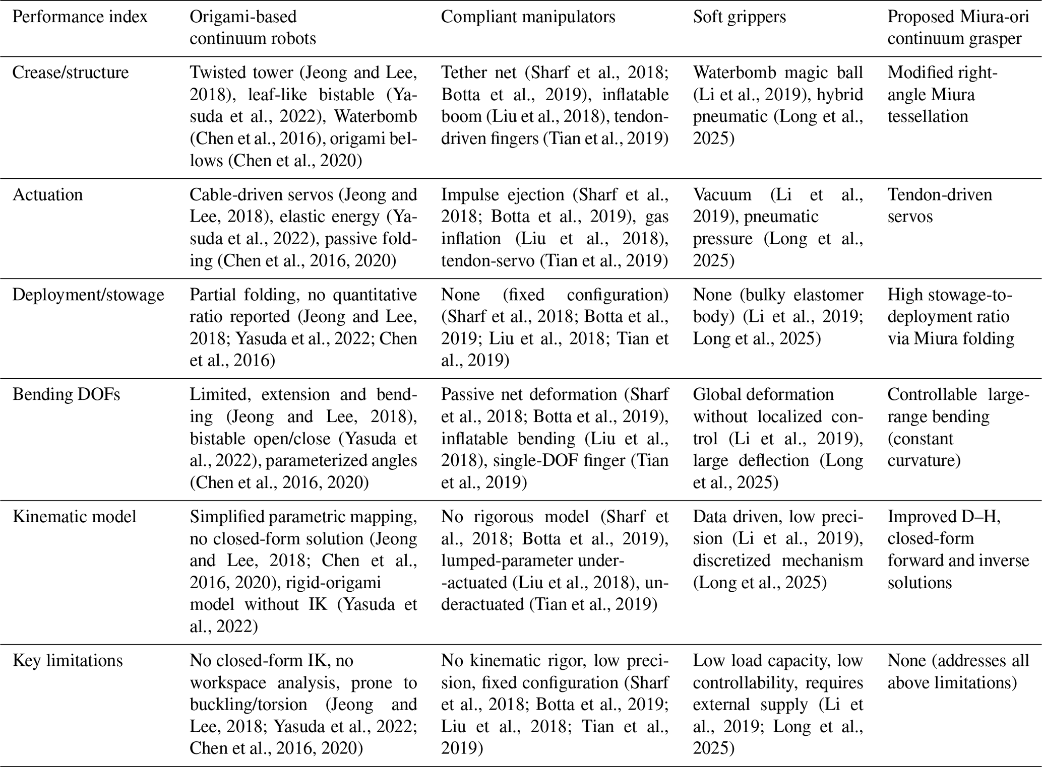
As summarized in Table 1, the proposed Miura-ori continuum manipulator outperforms existing origami-based continuum robots (Jeong and Lee, 2018; Yasuda et al., 2022; Chen et al., 2016, 2020), compliant manipulators (Sharf et al., 2018; Botta et al., 2019; Liu et al., 2018; Tian et al., 2019) and soft grippers (Li et al., 2019; Long et al., 2025) across six key performance indices: (i) structure, modified right-angle Miura tessellation enabling both folding and bending; (ii) deployment, high stowage-to-deployment ratio absent in existing designs; (iii) bending, controllable large-range motion via constant-curvature assumption; (iv) kinematics, closed-form forward and inverse solutions through an improved Denavit–Hartenberg (D–H) formulation (Jones and Walker, 2006); (v) workspace, quantitative validation via Monte Carlo simulation; and (vi) space suitability, integrating modular design principles (Post et al., 2021) and intelligent control frameworks (Yu et al., 2026). This work addresses the limitations identified in all three categories and provides a new technique for flexible on-orbit capture.
(Jeong and Lee, 2018)(Yasuda et al., 2022)(Chen et al., 2016)(Chen et al., 2020)(Sharf et al., 2018; Botta et al., 2019)(Liu et al., 2018)(Tian et al., 2019)(Li et al., 2019)(Long et al., 2025)(Jeong and Lee, 2018)(Yasuda et al., 2022)(Chen et al., 2016, 2020)(Sharf et al., 2018; Botta et al., 2019)(Liu et al., 2018)(Tian et al., 2019)(Li et al., 2019)(Long et al., 2025)(Jeong and Lee, 2018; Yasuda et al., 2022; Chen et al., 2016)(Sharf et al., 2018; Botta et al., 2019; Liu et al., 2018; Tian et al., 2019)(Li et al., 2019; Long et al., 2025)(Jeong and Lee, 2018)(Yasuda et al., 2022)(Chen et al., 2016, 2020)(Sharf et al., 2018; Botta et al., 2019)(Liu et al., 2018)(Tian et al., 2019)(Li et al., 2019)(Long et al., 2025)(Jeong and Lee, 2018; Chen et al., 2016, 2020)(Yasuda et al., 2022)(Sharf et al., 2018; Botta et al., 2019)(Liu et al., 2018)(Tian et al., 2019)(Li et al., 2019)(Long et al., 2025)(Jeong and Lee, 2018; Yasuda et al., 2022; Chen et al., 2016, 2020)(Sharf et al., 2018; Botta et al., 2019; Liu et al., 2018; Tian et al., 2019)(Li et al., 2019; Long et al., 2025)Table 1Comparison with existing origami continuum robots, compliant manipulators and soft grippers.
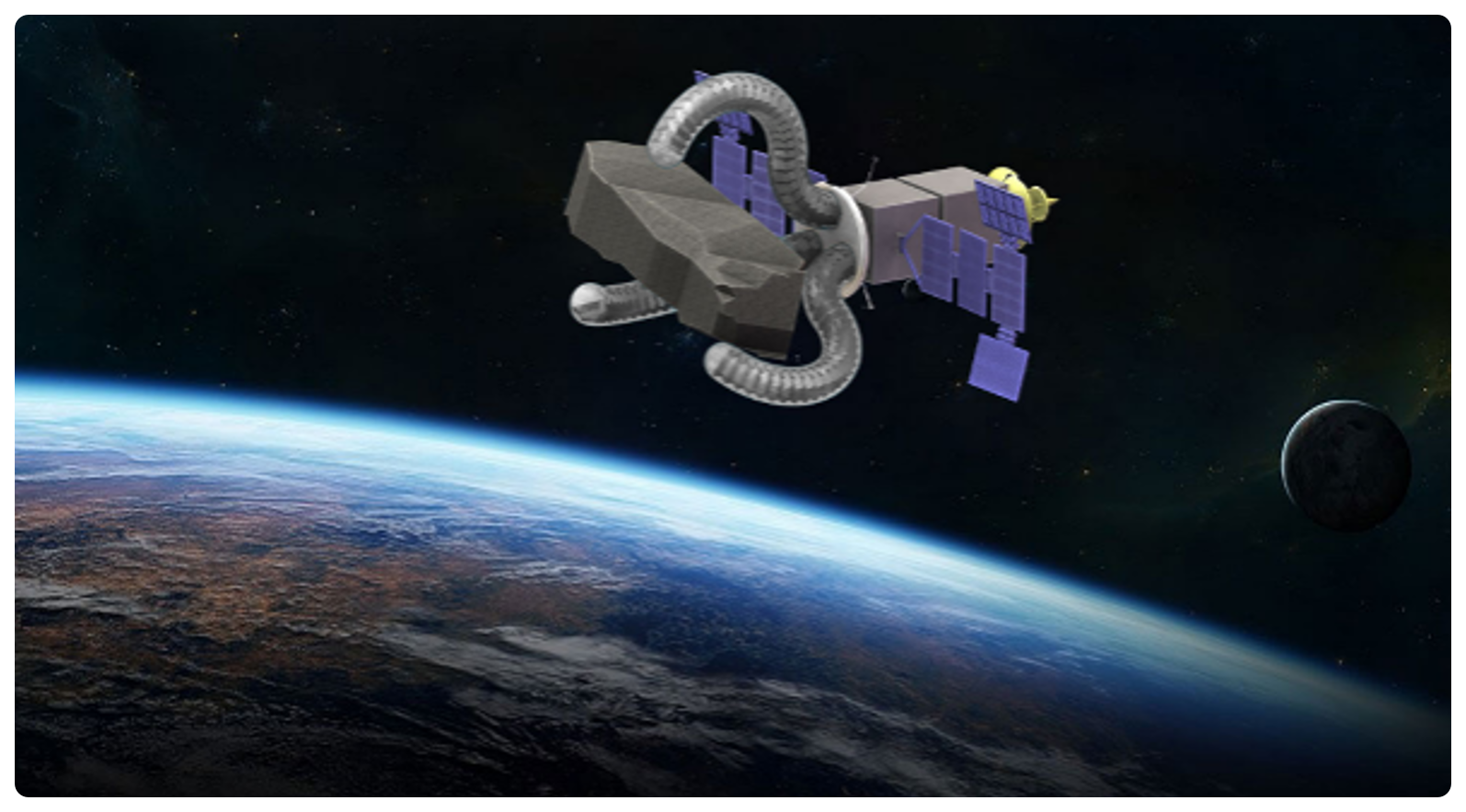
Motivated by the above, this paper presents an end-effector continuum capture device based on the Miura-ori pattern. The folding sequence of Miura-ori naturally mirrors continuum deformation, yielding a lightweight, highly flexible and low-cost system capable of absorbing impact energy during capture. The kinematic redundancy inherent to origami continua enables grasping of space debris with arbitrary geometries. When mounted on a servicing spacecraft, the device can capture non-cooperative targets, including tumbling debris, spinning defunct satellites and evasive objects (Fig. 1). The proposed configuration overcomes the limitations of rigid-capture systems that rely on dedicated grappling interfaces, broadening the spectrum of retrievable debris, enhancing operational flexibility, relaxing precision-control requirements, and by virtue of its low mass and stowable volume, significantly reducing launch costs.
2.1 Parametric design of Miura creases
Starting from the two-dimensional crease pattern of the conventional Miura unit (Fig. 2a), we rearrange the peripheral creases so that the four corners become right angles, thereby transforming the Miura cell into a rectangular unit. As illustrated in Fig. 2b, the new crease pattern is tessellated from these rectangular units in an n×m array; joining the left and right edges of the pattern produces an origami tube. Each new unit is composed of two distinct right-angled trapezoids that together form a rectangle. The rectangle has an overall length of (a0+b0) and a center-line length of (a1+b1), with a width of 2h; within each unit, an inclined crease subtends an angle α with the horizontal axis.
Rolling the Miura-derivative rectangular array illustrated in Fig. 2b yields an origami tube whose cross-section is depicted in Fig. 2c. The tube forms a hollow n-sided frustum; the outer and inner polygons have edge lengths of (a0−b0) and (a1−b1), respectively, subtending a central angle θ. The fully folded tube is characterized by an inner radius r1 and an outer radius rd.
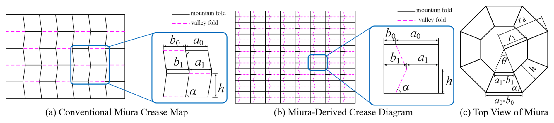
Figure 2Crease patterns and cross-sectional geometry of the proposed Miura-derived origami continuum.
To ensure the rigor of geometric derivation, the following assumptions are adopted for the Miura-derived origami unit. (1) All creases are ideal hinges with no thickness or deformation. (2) All facet panels are rigid and do not undergo in-plane deformation during folding. (3) The origami tube is formed by symmetric tessellation of uniform rectangular units. (4) Folding motion follows a continuous and single-valued geometric mapping without self-intersection. The following geometric relationships are derived: . In the equations, ai and bi denote the horizontal length parameters of the creases, and θ is the central angle of the regular polygon; the same notation is used hereafter. The inclined crease angle is defined as , while the inner radius and outer radius characterize the geometric dimensions of the origami tube in terms of crease structural parameters.
By establishing the geometric parameters of the folding pattern, we derived closed-form expressions that relate the origami tube's inner and outer diameters to these parameters. This relationship quantifies how tube dimensions vary with design variables, providing a theoretical basis for the design of origami-based tubular space structures.
2.2 Structural design of a Miura-origami-inspired continuum for spatial applications
The three-dimensional configuration of the Miura-derived origami continuum satisfies the following. (1) The dihedral folding angle β is uniformly distributed along the axial direction. (2) All units deform synchronously without relative sliding or distortion. (3) The tubular structure maintains axisymmetric deformation during deployment and bending.
To investigate the spatial configuration of the Miura-origami-inspired continuum, we define the dihedral folding angle of a rectangular unit as β and its width as Δz during deployment. These two variables govern the degree of folding of the rectangular unit, as illustrated in Fig. 3a. After n rectangular units are tessellated into a tubular configuration, a direct relationship exists between the geometric parameters of the two-dimensional crease pattern and those of the three-dimensional folded state. As depicted in Fig. 3b, the inner radius r1 increases monotonically as the origami tube is deployed. Specifically, the rotation angle θ of each trapezoidal facet illustrated in Fig. 2c is . In the equation, β denotes the dihedral angle formed along the creases after folding into a spatial tubular structure.
As illustrated in Fig. 3c, the overall length H of the Miura-origami continuum can be expressed as
In the equation, m denotes the number of unit rows in the crease pattern, and h corresponds to the height of the trapezoidal facet that constitutes the polygonal origami tube.
By tailoring the geometric parameters of the crease pattern, the structural deformation required for bending and compression can be precisely engineered and modulated (Fang et al., 2022). Moreover, the structure cannot achieve a fully folded state without simultaneous deformation of the origami facets; consequently, the strain energy under compression is stored not only in the creases but also within the compliant facets, thereby imparting enhanced elasticity that facilitates elastic recovery of the continuum (Yu et al., 2026). Therefore, by judiciously designing the crease parameters, continuum structures with tailored lengths and stiffnesses can be systematically realized.
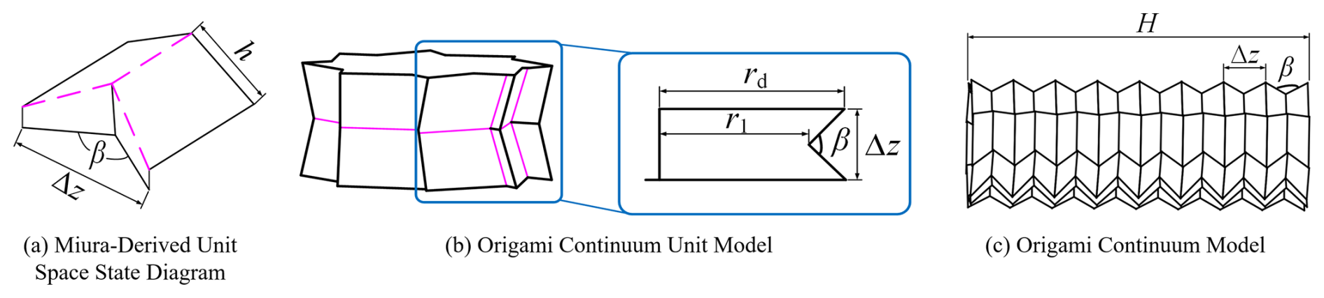
Figure 3Spatial configuration and geometric model of the proposed Miura-origami-inspired continuum.
3.1 Forward kinematics of the Miura-origami continuum robot
To establish a rigorous mapping from crease geometry to continuum kinematics, the following assumptions are introduced. (1) The Miura-derived origami continuum deforms with constant curvature (Jones and Walker, 2006) along its axis. (2) Bending motion is constrained within a single plane for capture tasks (ϕ=0). (3) The relationship between folding angle βi and cable actuation is monotonic and continuous. (4) The modified D–H method is valid under small-deformation and rigid-panel assumptions.
As illustrated in Fig. 4, actuation cables are routed along its lateral edges and anchored to each segment, and the magnitude of bending is characterized by the spatial folding angles βi (). The pose of the continuum axis can be fully described by three independent parameters: the arc length s along the continuum, its curvature κ, and the curvature angle ϕ. A mapping is subsequently derived that relates the spatial folding angle β of the origami tube to the continuum's pose variables.
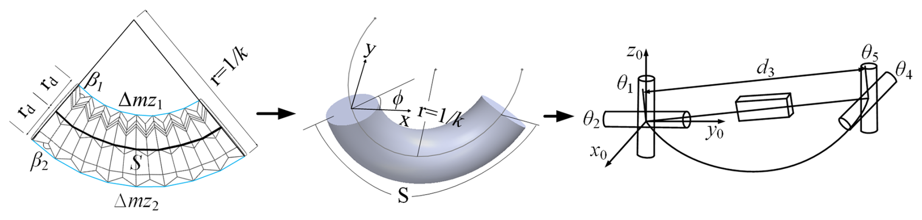
Subsequently, by mapping the continuum variables s, κ, and ϕ to the Denavit–Hartenberg (D–H) parameters, the end-effector coordinates (x, y) of the Miura-origami-derived continuum can be derived. The derivation of the forward kinematics is formulated as follows: , where x and y denote the Cartesian coordinates of the end-effector; θ and d are the parameters obtained via the D–H convention; and the functions f1 and f2 are defined in Eqs. (12) and (8), respectively.
3.2 Pose-equivalent model of the Miura-origami continuum
The equivalent model of the Miura-origami tube continuum aims to establish a mapping between the actuating cable lengths and the pose of the continuum robot. Based on the established relationship between the spatial folding angles βi of the Miura-origami tube and the shape variables s, κ, and ϕ of the continuum robot joints, and in accordance with the operational requirements of the capture robot – wherein the mechanism bends within a single plane – the curvature angle is set to zero (ϕ=0). Consequently, the corresponding functional relationship is obtained as follows:
In the equation, m denotes the number of unit rows in the crease pattern, h is the height of the trapezoidal facet forming the origami-tube polygon, and rd represents the circumscribed radius of the origami-tube polygon.
3.3 Kinematic model of the Miura-origami continuum robot
The Miura-origami-derived continuum comprises one revolute joint and one prismatic joint, which collectively enable its bending degree of freedom. Its kinematic model can therefore be reduced to a virtual rigid-link robot consisting of a revolute joint at the base, a prismatic joint at the mid-span and a second revolute joint at the distal end, as illustrated in Fig. 4.
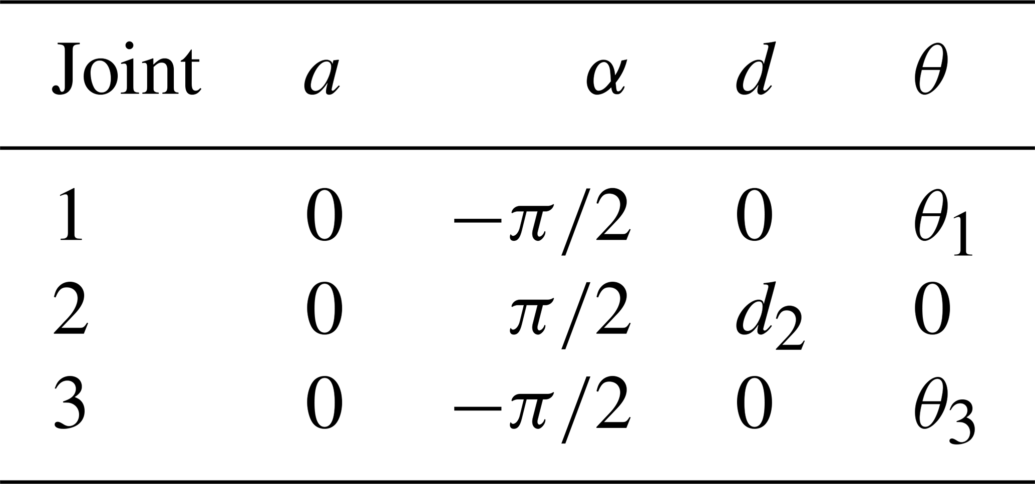
The coordinates of the continuum end point are first determined by the base revolute joint and the mid-span prismatic joint. A subsequent rotation of the distal revolute joint aligns the local coordinate frame with the tangent vector at the continuum tip, thereby defining the full pose of the Miura-origami continuum robot. The robot kinematics are formulated using the modified D–H convention; the corresponding parameters are listed in Table 2. Owing to the kinematic symmetry, the joint variables of the base and top revolute joints are related by θ1=θ3, enabling the derivation of the homogeneous transformation matrix .
The kinematic equivalence between the origami crease geometry and the virtual rigid-link robot is established under the condition that the bending curvature generated by folding angles β1,β2 is uniquely mapped to the D–H joint variables . Due to kinematic symmetry, θ1=θ3 holds throughout the motion. The prismatic variable d2 represents the effective chord length corresponding to the origami continuum bending.
Applying the serial-chain kinematic transformation, the generalized form is obtained as follows:
The end-effector pose of the Miura-origami-derived continuum with respect to the fixed frame is obtained by sequentially right multiplying the homogeneous transformation matrices of each joint . Substituting the D–H parameters yields the following explicit homogeneous transformation matrix:
In the expression, c denotes cos, and s denotes sin.
By exploiting the established relationships between the D–H joint variables θi and di of the Miura-origami-derived continuum robot and its shape variables s and κ, the corresponding functional relations are obtained as follows:
3.4 Workspace determination of the Miura-origami continuum
The workspace is rigorously derived based on the geometric constraints of crease parameters and the allowable range of folding angles. All boundary conditions of the workspace are consistent with the physical folding limits of the Miura-derived origami structure, ensuring no invalid or non-physical configuration is included.
As illustrated in Fig. 4, the position of the Miura-origami-derived continuum end-effector center is fully determined by the arc length S and the curvature κ; consequently, only the joint variables of the first two joints are required to locate this point. Thus, the reachable positional workspace is obtained once the homogeneous transformation matrix () of the end-effector center with respect to the fixed frame has been derived.
This matrix () is obtained by sequentially right multiplying the homogeneous transformation matrices of the first three joints:
In the expression, c denotes cos, and s denotes sin.
Based on the analysis of a single Miura-origami-derived continuum, the admissible ranges of the Denavit–Hartenberg (D–H) joint variables are determined from the prescribed bounds of the shape variables s, κ, and ϕ via their established functional relationships.
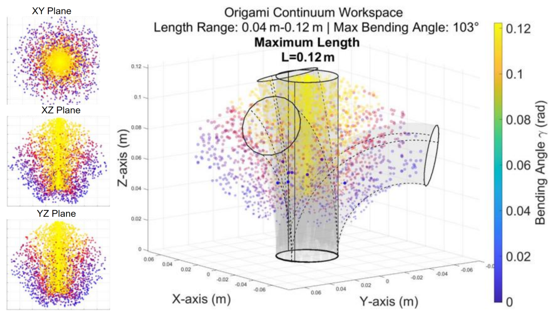
Employing the Monte Carlo method to sample the continuum end-effector center yields the workspace of the Miura-origami-derived continuum, depicted in Fig. 5. A three-dimensional visualization of the origami-continuum workspace, generated via Monte Carlo sampling, further elucidates the reachable domain and deformation characteristics, as shown in Fig. 5.
To further enhance the depth and rigor of the workspace analysis, a deep analysis of grasping workspace is supplemented herein, focusing on the dependence of workspace characteristics on key design parameters and its relevance to the intended on-orbit capture task.
Based on the geometric and kinematic models established in the former section, a systematic sensitivity analysis is conducted to quantify the effects of core design parameters on the workspace of the Miura-derived origami continuum. The key design parameters investigated include the number of finger units “fn”, the height of the finger “fL”, the radius of the finger “fr”, and the outer circumscribed radius “bR”, which are critical to the structural deformation and workspace performance.
The quantitative relationships between each parameter and workspace characteristics are derived as follows. (1) The workspace volume V is positively correlated with “fn” and “fL”, following the trend within the allowable structural constraint, which is attributed to the increased deformable length and cross-sectional expansion of the continuum with larger “fn” and “fL”. (2) The maximum bending angle θmax is primarily determined by the radius of the finger “fr” and the geometric constraints of the modified Miura crease pattern. (3) The outer circumscribed radius “bR” affects the lateral reach of the workspace, with a larger “bR” leading to a wider lateral coverage but a slight reduction in the maximum bending angle due to increased structural rigidity. Comparative simulations are performed by varying each parameter while keeping others constant, and the results are visualized in the revised Fig. 6 to intuitively present the impact of each parameter on the workspace.
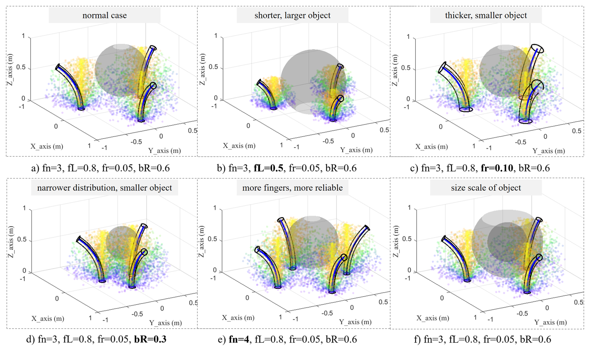
The workspace of the Miura-derived origami continuum is tailored to meet the practical demands of on-orbit non-cooperative target capture, and its relevance to the intended task is elaborated as follows. First, the workspace size is designed to match the typical size range of small- to medium-sized space debris, ensuring effective enveloping of targets with varying dimensions. Second, the flexible bending capability and continuous deformability of the workspace enable the gripper to adapt to irregular target geometries (e.g., spherical, cubic, irregular fragments) by passively conforming to the target surface, which is a key advantage for capturing non-cooperative targets without predefined grappling interfaces. Furthermore, the Monte Carlo sampling-based workspace analysis is supplemented with statistical evaluations of the reachable pose distribution. The adjustable reachable range of the workspace facilitates obstacle avoidance in complex orbital environments, where the gripper can adjust its posture within the workspace to avoid collisions with other orbital objects or spacecraft components.
3.5 Inverse kinematics of the Miura-origami continuum robot
Upon completion of the forward-kinematic analysis of the Miura-origami-derived continuum, the pose of the continuum robot and the position of its end-effector can be determined for any specified set of origami parameters.
To facilitate robot control, the target coordinates must serve as the primary input; hence, given the end-effector position of the continuum, the corresponding actuation magnitudes βi must be determined. Consequently, an inverse-kinematics analysis of the Miura-origami-derived continuum is conducted.
From the forward-kinematic relationships given in former equations, we obtain
In the equation, m denotes the number of unit rows in the crease pattern, h is the height of the trapezoidal facet forming the origami-tube polygon, and rd represents the circumscribed radius of the origami-tube polygon.
Consequently, the spatial folding angle βi can be expressed explicitly in terms of the Cartesian coordinates x and y as follows: .
4.1 Comparative experiments on Miura-origami-based continuum robots
To validate the proposed theory, a Miura-origami-inspired continuum robot prototype actuated by dual servomotors with antagonistic tendons routed along both lateral sides was fabricated. A straight-line trajectory was selected; the corresponding spatial folding angles βi were computed from the prescribed coordinates and subsequently validated on the prototype, as reported in Table 3.
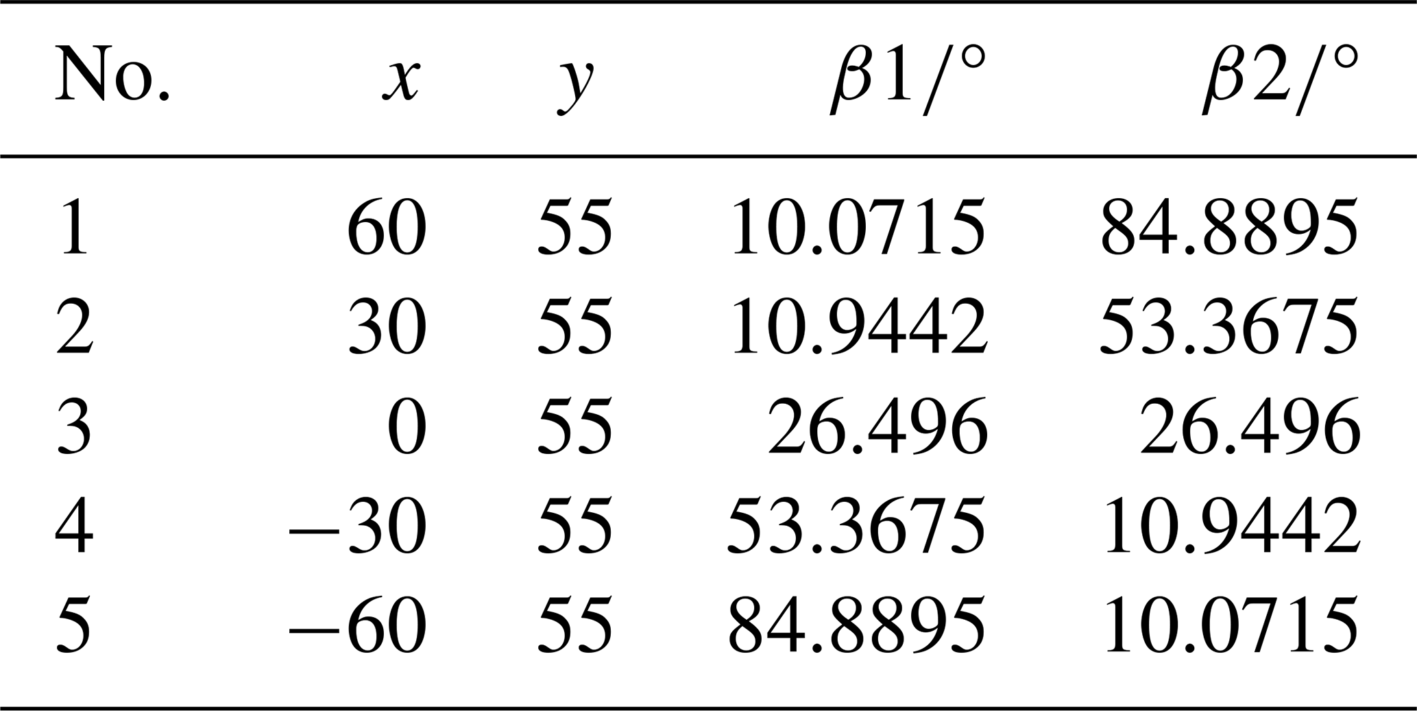
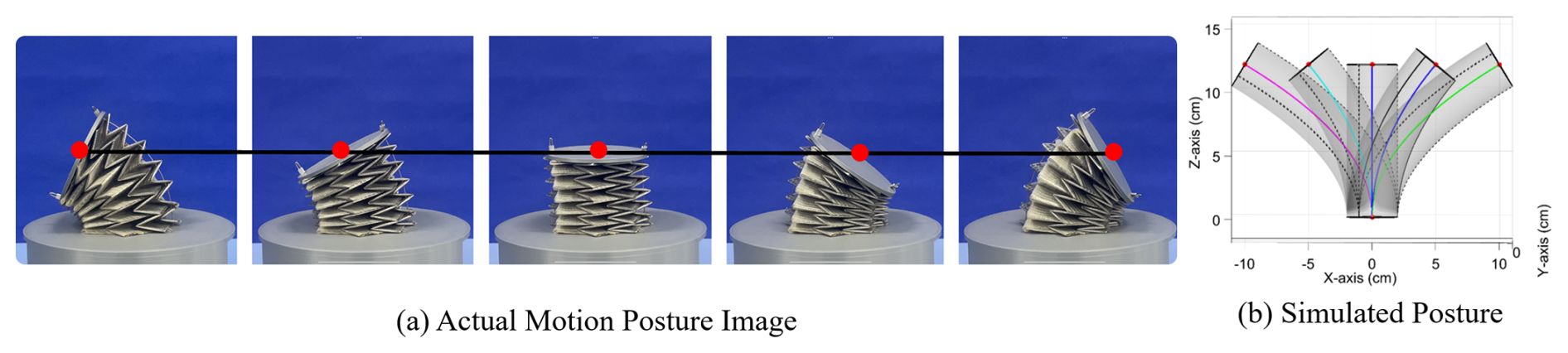
Figure 7Motion posture comparison of a continuum robot based on the Miura-derived origami principle.
The computed spatial folding angles βi were transmitted to the host computer, which actuated the tendons to regulate the configuration of the Miura-origami continuum robot, guiding its end-effector to the desired coordinates, as illustrated in Fig. 7. Grippers with varying bend angles maintain a constant height by adjusting β1 and β2; the MATLAB motion-simulation image in Fig. 7b confirms that, for the bending angles listed in Table 3, the end-effector center of the continuum robot remains at a uniform elevation. Figure 7a demonstrates that the Miura-origami-inspired continuum robot traces a rectilinear trajectory, thereby corroborating the accuracy of its inverse kinematics and validating the viability of the proposed path-planning strategy.
To further validate the reliability of the proposed kinematic model, quantitative evaluations of positioning accuracy and repeatability are conducted via repeated positioning tests. Figure 8 presents the experimental setup and measurement results of the repeated positioning test, where Fig. 8a shows the test device and Fig. 8b illustrates the comparison between measured and theoretical coordinates.

As shown in Fig. 8a, the end-effector position P(xp,yp) is measured under a fixed tendon actuation configuration, and 30 repeated measurements are performed to obtain the trajectory tracking data. Figure 8b presents the measured coordinate values (blue fitted curves) and the theoretical values predicted by the kinematic model (red dashed lines). The theoretical coordinates are x=51.7449 and y=85.8737 mm, while the measured results exhibit small fluctuations around these values.
The maximum absolute deviation in the x direction is less than 3 mm, and the maximum absolute deviation in the y direction is less than 2 mm, corresponding to a relative error of less than about 5.8 % and 2.3 %, respectively. These results demonstrate that the proposed kinematic model achieves high positioning accuracy and excellent repeatability under the same actuation input, confirming its reliability for trajectory prediction and control.
4.2 Prototype of a Miura-origami-based space capture robot
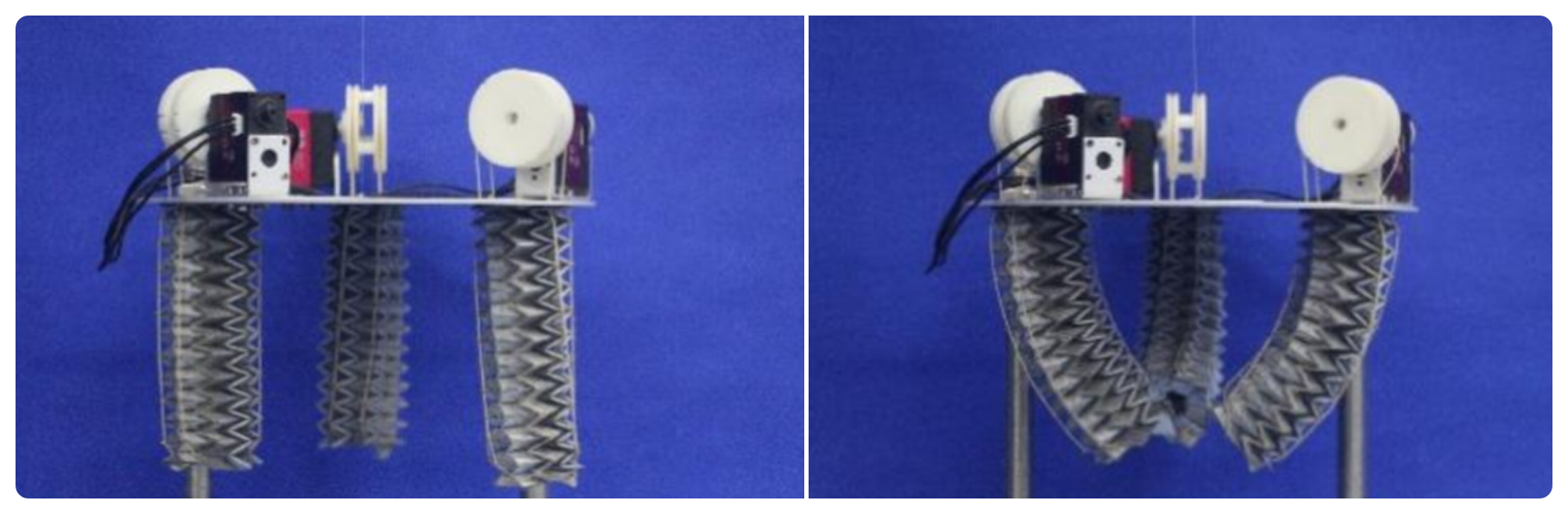
As depicted in Fig. 8, the prototype employs tendon-driven actuation: three origami continuum segments are individually actuated by a single servomotor that tensions or releases the tendons via a pulley mechanism, thereby controlling the motion of each segment. Low-stretch Kevlar tendons were selected for the drive lines, and bus-type ZP20D servomotors were used for actuation.
4.3 Grasping experiments of the Miura-derived origami-based space grasping robot
4.3.1 Adaptability and stability experiments for objects with different geometric shapes
To preliminarily assess the manipulative capability of the prototype, rubber fingertips may be fitted to enhance frictional grasping; however, such fingertip covers are not included in the present prototype (as shown in Fig. 9). The control sequence for the Miura-origami-based grasping device is programmed in four discrete phases: (1) pre-grasp positioning, (2) object acquisition, (3) secure grasp with concurrent finger flexion, and (4) object release. The entire cycle lasts approximately 10 s.
Given the unique characteristics of compliant grasping by continuum mechanisms, a diverse set of test objects with varying shapes is prepared, including regular geometric primitives (spheres, cubes), simulated meteorite fragments and various irregular bodies, to validate the gripper's shape adaptability.
Figure 10 illustrates the grasping process for a standard sphere, a regular prism, and for a simulated meteorite fragment. Observations of the prototype's interaction with these three distinct objects demonstrate that the origami continuum can passively conform to the target's surface profile. Leveraging the continuous bending characteristics of the Miura structure, the gripper generates redundant enclosures around the target, thereby achieving stable grasping. These results preliminarily verify the feasibility of the prototype for capturing non-cooperative targets with irregular geometries.

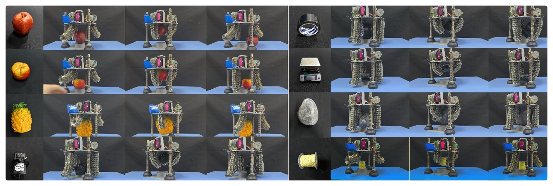
To further quantify the shape adaptability, Fig. 11 presents the grasping experiments for various irregular objects. When interacting with irregular bodies, the continuum not only conforms to the target surface but also actively adjusts the relative curvature of the three fingers. This allows the origami edges to embed into the corners of the object, forming a physical interlock, while the distal segments of the continuum penetrate into concave regions for positional locking. For the simulated meteorite fragments, 20 repeated grasping tests were conducted under identical experimental conditions. Statistical results show a grasping success rate of 93.7 %. The data indicate that the prototype exhibits extremely high adaptability and success rates for geometries with concave features and smooth curved surfaces. Although the success rate slightly decreases for irregular bodies with sharp edges, the overall performance demonstrates excellent geometric generalization capability and grasping stability.
4.3.2 Quantitative validation experiments of load-bearing capacity and grasping success rate
In space applications, grasping mechanisms must withstand the inertial loads of non-cooperative targets, making load-bearing capacity a key performance indicator. To this end, a quantitative load-bearing experiment is designed.
A custom polyhedral container with an internal storage cavity is used as the standard target object. The empty mass of the container is 115.8 g. By sequentially adding calibrated weights inside the container, the prototype's ultimate capability to grasp the target from a desktop and maintain stable suspension for 10 s is evaluated.
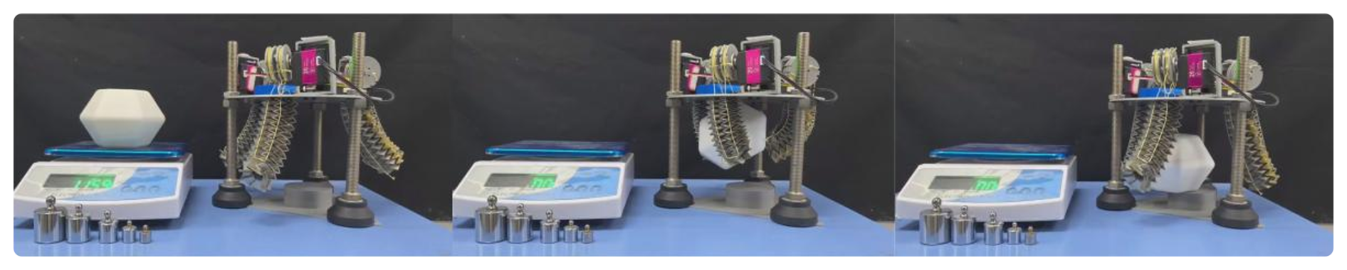
The experimental procedure is illustrated in Fig. 12. Within the test range where the total mass of the container increases from 115.8 to 365.8 g (with 50 g increments as the mass gradient), 10 repeated lifting and grasping trials are performed for each mass level. The results are summarized as follows: when the total load mass is ≤265.8 g, the grasping success rate remains at 100 %, with no observed slippage or fingertip detachment during suspension, indicating excellent load-holding stability. When the load increases to the range of 265.8 to 315.8 g, the normal-force component due to gravity increases significantly. The prototype primarily relies on friction between the three fingers and the target surface to resist slippage, resulting in a reduced grasping success rate of approximately 85 %. When the test mass reaches 365.8 g (exceeding 1.99 times the mass of the prototype's continuum structure), the radial clamping force provided by the tendon-driven actuation system is insufficient to overcome the slip effect caused by gravity, leading to grasping failure.
This set of quantitative experiments defines the maximum effective load range and load failure boundary of the Miura-derived origami-based grasping robot at the current scale. The results confirm that even without high-friction fingertip sleeves, the prototype is capable of stably grasping non-cooperative targets with a certain mass. Future improvements, such as the integration of aerospace-grade materials and high-friction coatings, are expected to significantly enhance its load-bearing capacity.
4.4 Discussion on ground validation and on-orbit deployment challenges
All prototype experiments and performance validations presented in this study are conducted under ground-based atmospheric and 1 g gravitational conditions, which serve as a proof-of-concept demonstration to verify the feasibility of the proposed Miura-derived origami continuum grasping mechanism. It is necessary to clearly distinguish between such ground-based verification and the actual requirements for real on-orbit space deployment.
In practical space applications, the gripper will face a series of critical challenges, including microgravity dynamics, extreme thermal vacuum environment, space radiation and long-term structural stability, as well as the capture of tumbling, non-cooperative and high-speed moving targets. In addition, the current prototype uses conventional engineering materials, which cannot meet the aerospace requirements of low outgassing, high-temperature resistance and radiation resistance. The actuation system, control strategy and reliability design also need to be further upgraded for on-orbit service.
This work focuses on the conceptual design, kinematic modeling and functional verification of the origami continuum space manipulator. Subsequent research will carry out space-adapted optimization, including aerospace-grade material selection, environmental adaptability testing and dynamic control for non-cooperative targets, so as to bridge the gap between the ground prototype and practical on-orbit applications.
This paper presents a Miura-ori end-effector continuum gripper that synergizes deployable folding with controllable large-range bending for capturing non-cooperative space debris of irregular geometry and variable dimensions. Existing rigid robotic systems are limited to cooperative targets with standardized interfaces, whilst conventional compliant mechanisms lack kinematic rigor and controllable deformability. To address these gaps, explicit geometric relationships between crease parameters and unit-cell configurations are derived, furnishing a parametric model that links two-dimensional fold patterns to three-dimensional deployed shapes and that provides a design-oriented theoretical foundation.
-
An improved Denavit–Hartenberg formulation yields closed-form forward and inverse kinematic solutions that map origami structural variables to the end-effector pose. Reachable workspace boundaries are computed via Monte Carlo simulation, offering a priori validation for mechanical design and motion planning.
-
A tendon-driven three-finger prototype is manufactured and experimentally tested. Forward-kinematic measurements demonstrate close agreement between predicted and measured end-effector positions across the full folding range. Inverse-kinematics commands successfully steer the continuum terminus to prescribed spatial coordinates within the derived workspace, confirming analytical correctness.
-
Grasping trials on spheres, prisms and irregular meteorite-fragment simulants demonstrate passive shape adaptation, positional locking and stable enclosure without high-friction fingertip sleeves. Quantitative load-bearing tests establish a maximum effective payload of 265.8 g with a 100 % success rate over 10 repeated trials, defining the load failure boundary at the current scale. These results validate the controllability and adaptability of the proposed mechanism for space-compliant grasping. Future work will extend to microgravity dynamics, aerospace-grade material selection, thermal-vacuum environmental testing and closed-loop dynamic control for on-orbit deployment.
| Symbol | Description | ||
| a0,b0 | Outer edge length parameters of the Miura unit | ||
| a1,b1 | Inner edge length parameters of the Miura unit | ||
| h | Half-width of the rectangular origami unit | ||
| α | Inclined angle of the crease relative to the | ||
| horizontal axis | |||
| θ | Central angle of the regular polygonal | ||
| cross-section | |||
| r1 | Inner radius of the fully folded origami tube | ||
| rd | Outer radius of the fully folded origami tube | ||
| β | Dihedral folding angle of the rectangular | ||
| origami unit | |||
| m | Number of axial unit rows | ||
| H | Total length of the origami continuum | ||
| s | Arc length of the continuum backbone | ||
| k | Curvature of the continuum (, ρ | ||
| is bending radius) | |||
| ϕ | Bending azimuth angle | ||
| β1,β2 | Left/right spatial folding angles of the | ||
| origami tube | |||
| θi,di | Modified D–H joint variables | ||
| Δz | Axial width of a single unit in the deployed state |
The underlying software code is not publicly accessible. Access to the code may be granted upon reasonable request to the corresponding author, subject to approval.
The underlying research data are not publicly accessible. Access to the data may be granted upon reasonable request to the corresponding author, subject to approval.
R.L. and M.S. conceived the idea and designed the research. R.L. performed the theoretical analysis and simulations. R.L., M.S., K. W. and J.Z. conducted the experiments. R.L., M.S., K.W. and M.Z. analyzed the data. H.G., C.W. and H.Y. supervised the project and provided critical feedback. R.L. and M.S. wrote the original draft. All authors reviewed and edited the paper.
The contact author has declared that none of the authors has any competing interests.
Publisher's note: Copernicus Publications remains neutral with regard to jurisdictional claims made in the text, published maps, institutional affiliations, or any other geographical representation in this paper. The authors bear the ultimate responsibility for providing appropriate place names. Views expressed in the text are those of the authors and do not necessarily reflect the views of the publisher.
The authors thank the State Key Laboratory of Robotics and Systems, Harbin Institute of Technology, and the Engineering Center for Space Utilization of the Chinese Academy of Sciences for their technical support.
This work was supported by the National Natural Science Foundation of China (grant nos. 52305014, 52105011), the Young Innovative Talents Project of Guangdong Province (grant no. 2021KQNCX071), the Guangdong Higher Education Society Higher Education research project (grant no. 22GQN25), the Tertiary Education Scientific research project of the Guangzhou Municipal Education Bureau (grant no. 202235334), and the Basic and Applied Basic Research Projects of Guangzhou (grant no. SL2023A04J00685).
This paper was edited by Pengyuan Zhao and reviewed by Qasim Atiyah and one anonymous referee.
Botta, E. M., Sharf, I., and Misra, A. K.: Simulation of tether-nets for capture of space debris and small asteroids, Acta Astronaut., 155, 448–461, https://doi.org/10.1016/j.actaastro.2018.07.046, 2018. a, b, c, d, e, f, g, h, i
Chen, W. H., Misra, S., Gao, Y., Lee, Y. J., Koditschek, D. E., Yang, S., and Sung, C. R.: A Programmably Compliant Origami Mechanism for Dynamically Dexterous Robots, IEEE Robot. Auto. Lett., 5, 2131–2137, https://doi.org/10.1109/LRA.2020.2970637, 2020. a, b, c, d, e, f, g
Chen, Y., Feng, H., Ma, J., Peng, R., and You, Z.: Symmetric waterbomb origami, P. Roy. Soc. A-Math. Phy., 472, 20150846, https://doi.org/10.1098/rspa.2015.0846, 2016. a, b, c, d, e, f, g, h
Debus, T. and Dougherty, S.: Overview and performance of the Front-End Robotics Enabling Near-Term demonstration (FREND) robotic arm, Proceedings of the AIAA Infotech@Aerospace Conference, Seattle, Washington, https://doi.org/10.2514/6.2009-1870, 2009. a, b
Fang, H., Wu, H., Liu, Z., Zhang, Y., and Wang, K.: Advances in the Dynamics of Origami Structures and Origami Metamaterials, Chinese J. Theor. Appl. Mechan., 54, 1–38, https://doi.org/10.6052/0459-1879-21-478, 2022. a, b, c
Jeong, D. and Lee, K.: Design and analysis of an origami-based three-finger manipulator, Robotica, 36, 261–274, https://doi.org/10.1017/S0263574717000340, 2017. a, b, c, d, e, f, g, h
Jones, B. A. and Walker, I. D.: Kinematics for multisection continuum robots, IEEE Trans. Robot., 22, 43–55, https://doi.org/10.1109/TRO.2005.861458, 2006. a, b, c
Li, S., Stampfli, J. J., Xu, H. J., Malkin, E., Villegas Diaz, E., Rus, D., and Wood, R. J.: A Vacuum-driven Origami “Magic-ball” Soft Gripper, Proceedings of the 2019 International Conference on Robotics and Automation (ICRA), IEEE, 7401–7408, https://doi.org/10.1109/ICRA.2019.8794068, 2019. a, b, c, d, e, f, g, h
Liu, H., Wei, C., Tian, J., and Guo, L.: Dynamics Modeling and Analysis of the Inflatable Net System for Space Capture, J. Mechan. Eng., 54, 145–152, https://doi.org/10.3901/JME.2018.22.145, 2018. a, b, c, d, e, f, g, h, i
Long, Y., Zhu, X., Chen, G., Wang, Y., Wang, H., Liu, Q., and Shi, P.: A high-performance elastic-soft hybrid pneumatic actuator with origami structure, Int. J. Mechan. Sci., 287, 109935, https://doi.org/10.1016/j.ijmecsci.2025.109935, 2025. a, b, c, d, e, f, g, h
Nishida, S. I., Kawamoto, S., Okawa, Y., Asakura, A., Mikami, N., and Funase, R.: Space debris removal system using a small satellite, Acta Astronaut., 63, 635–639, https://doi.org/10.1016/j.actaastro.2008.07.001, 2008. a
Post, M. A., Yan, X. T., and Letier, P.: Modularity for the future in space robotics: a review, Acta Astronaut., 189, 530–547, https://doi.org/10.1016/j.actaastro.2021.09.007, 2021. a, b
Sharf, I., Thomsen, B., Botta, E. M., Gellatly, R., and Misra, A. K.: Experiments and simulation of a net closing mechanism for tether-net capture of space debris, Acta Astronaut., 139, 332–343, https://doi.org/10.1016/j.actaastro.2017.07.026, 2017. a, b, c, d, e, f, g, h, i, j
Tian, J., Wei, C., Luo, M., Wu, X., Song, H., and Dong, X.: Parametric Research on underactuated tendon-driven grasping mechanism for space capture operation, Int. J. Precis. Eng. Man., 21, 237–247, https://doi.org/10.1007/s12541-019-00223-9, 2019. a, b, c, d, e, f, g, h
Yasuda, H., Johnson, K., Arroyos, V., Yamaguchi, K., Raney, J. R., and Yang, J.: Leaf-like origami with bistability for self-adaptive grasping motions, Soft Robot., 9, 938–947, https://doi.org/10.1089/soro.2021.0008, 2022. a, b, c, d, e, f, g, h
Yu, H., Lv, M., Hu, B., Zhang, Y., and Zhao, P.: Review article: A review of control technologies for soft robots: from structural design to intelligent control, Mech. Sci., 17, 313–332, https://doi.org/10.5194/ms-17-313-2026, 2026. a, b, c
- Abstract
- Introduction
- Design of the Miura-derivative origami continuum
- Kinematic analysis of the Miura-origami-derived continuum
- Prototype design and experiments
- Conclusions
- Appendix A: Nomenclature of geometric parameters
- Code availability
- Data availability
- Author contributions
- Competing interests
- Disclaimer
- Acknowledgements
- Financial support
- Review statement
- References
- Abstract
- Introduction
- Design of the Miura-derivative origami continuum
- Kinematic analysis of the Miura-origami-derived continuum
- Prototype design and experiments
- Conclusions
- Appendix A: Nomenclature of geometric parameters
- Code availability
- Data availability
- Author contributions
- Competing interests
- Disclaimer
- Acknowledgements
- Financial support
- Review statement
- References