the Creative Commons Attribution 4.0 License.
the Creative Commons Attribution 4.0 License.
 | 22 May 2026
Reliability-aware physics-guided enhancement for sparse-path Lamb-wave defect imaging
Peijiang Li
Ting You
Sparse-path Lamb-wave imaging remains challenging because the available pitch–catch paths contribute unequally to defect localisation, and simple equal-weight fusion often produces diffuse and unstable hotspots. This study proposes a reliability-aware physics-guided framework for sparse-path Lamb-wave defect imaging. The method combines unified preprocessing and scattering-envelope extraction, delay-constrained single-path elliptical imaging, two-stage path-reliability weighting, and lightweight image refinement under a soft physics prior. Experimental validation is performed using paired intact–damaged measurements from an aluminium plate with a controlled through-hole defect, which serves as a representative compact scattering source for evaluating the sparse-path imaging chain. Physically aligned scattering-envelope model (SEM)-assisted auxiliary datasets are used for refinement learning and statistical assessment under the same geometry and delay-mapping convention. The results show that single-path imaging is strongly underdetermined, whereas multi-path fusion reduces localisation error from over 100 mm to the order of tens of millimetres. On the SEM-100 benchmark, the trained refinement stage further reduces the mean localisation error from 19.0 to 4.8 mm while substantially improving image quality. The proposed framework therefore provides a practical balance between physical interpretability, sparse sensing, and data-assisted enhancement for guided-wave inspection with limited reliable paths and scarce labelled data.
- Article
(6633 KB) - Full-text XML
- BibTeX
- EndNote


Guided Lamb waves are among the most widely used sensing modalities in structural health monitoring and non-destructive evaluation of plate-like structures because they offer a long interrogation range, high sensitivity to discontinuities, and straightforward integration with surface-bonded piezoelectric transducers. Recent progress has moved the field well beyond classical delay-and-sum localisation toward full-field imaging, sparse-array reconstruction, physics-aware signal processing, and learning-assisted diagnostics (Yang et al., 2023; Segers et al., 2022; Philibert et al., 2022; Wang et al., 2022; Segers et al., 2021). In parallel, phased-array and multimode compounding studies have shown that imaging quality can be improved substantially when delay modelling, phase consistency, and mode-sensitive information are handled explicitly rather than heuristically (Xu et al., 2023a; Li et al., 2023; Huang et al., 2024; Xu et al., 2024a). For practical structural health monitoring (SHM), however, the key requirement is not merely defect indication but rather stable localisation with interpretable images under limited sensing resources and imperfect operating conditions. Similar system-level thinking has also been emphasised in recent reviews of soft robotic control and solar-sail mission design, where structural design, physics-based modelling, actuation or mission constraints, and intelligent decision-making must be considered jointly rather than in isolation (Yu et al., 2026; Zhao et al., 2023).
This requirement becomes especially difficult in sparse-path settings. In many practical deployments, the number of usable actuator–sensor paths is constrained by wiring, access, geometry, or power, and so the acquired data do not satisfy the assumptions underlying full-wavefield or full-matrix-capture approaches. Existing studies have addressed this problem from several directions, including autoencoder-assisted delay-and-sum imaging, sparse and limited-view signal reconstruction, modular neural-network localisation, multi-path exploitation, probabilistic imaging, and sparse-reconstruction-based inversion (Yu et al., 2023; Wang et al., 2024; Gao et al., 2024; Zeng et al., 2022, 2025; Zhang et al., 2024b; Xue et al., 2025b, a). Nonetheless, the core difficulty remains unresolved: under a genuinely sparse sensing network, defect-sensitive information is distributed very unevenly across paths, and simple equal-weight fusion often produces diffuse hotspots, elevated artefacts, and unstable localisation.
In a sparse pitch–catch network, each individual path provides only a one-dimensional geometric constraint: a defect-scattered arrival maps the candidate defect to an actuator–receiver ellipse rather than to a unique point. Therefore, a single path may produce an elongated high-response manifold with many geometrically admissible locations. Reliable localisation requires the mutual intersection and consistency of several pathwise responses. When only a few paths are available, this intersection becomes sensitive to coupling variation, angular coverage, and path-dependent scattering strength, making sparse-path imaging intrinsically underdetermined rather than merely a reduced-channel version of dense-array imaging.
A closely related issue concerns the front-end representation of defect-sensitive information. Lamb-wave measurements are affected by dispersion, mode conversion, environmental variability, and path-dependent amplitude scaling. Accordingly, recent work has emphasised baseline-free strategies, local-wavenumber imaging, hyperbolic localisation, and robust feature representations that remain informative when pristine baselines are unavailable or unreliable (Segers et al., 2021, 2022; Zhu et al., 2024; Xu et al., 2023b; Barzegar et al., 2025). At the same time, there is increasing interest in reliability-aware or uncertainty-aware localisation, where the objective is not only to predict a damage position but also to assess how trustworthy that prediction is for a specific case (Khurjekar and Harley, 2024). This perspective is particularly important for sparse-path SHM, where a visually plausible image may still be dominated by unreliable path contributions.
A further question is how learning should be used. Deep learning has demonstrated clear potential in guided-wave imaging, corrosion mapping, and damage diagnosis when sufficiently rich datasets are available (Wang et al., 2022; Wu et al., 2021; Gonzalez-Jimenez et al., 2024; Zhang et al., 2024a). Learning has also been combined with coarse physical images through auto-encoder-assisted imaging, hybrid enhancement, and related refinement schemes (Yu et al., 2023; Zhang et al., 2024a; Luo et al., 2025). However, purely data-driven inference remains difficult to justify in many SHM scenarios, especially when labelled experimental data are scarce, when acquisition is costly, or when the output must remain physically interpretable. This limitation is even more evident for weakly scattering or early-stage damage, where recent nonlinear Lamb-wave studies have shown both the promise of damage-sensitive features and the difficulty of converting those features into reliable spatial images (Xu et al., 2024a, b). For constrained SHM problems, learning is therefore most persuasive when it refines a physically meaningful coarse image rather than replacing the underlying propagation model altogether.
Recent studies on anisotropic laminates, tapered plates, lap joints, and multi-damage configurations further indicate that reliable localisation on non-ideal structures requires path-dependent modelling and hybrid inference rather than a generic imaging recipe (Wu et al., 2022; Chen et al., 2024; Zhang et al., 2025; Zeng et al., 2025; Luo et al., 2025). However, a compact framework that jointly addresses three issues – the use of experimentally acquired sparse pitch–catch data, path-to-path reliability variation, and small-sample physics-guided enhancement – remains lacking. Motivated by this gap, the present work proposes a reliability-aware physics-guided framework for sparse-path Lamb-wave defect imaging. The method integrates unified preprocessing, delay-constrained single-path imaging, two-stage path reliability weighting, and lightweight image refinement under a soft physics prior. Rather than competing with full-wavefield imaging or large-array inspection in data-rich settings, the proposed strategy is designed for the more constrained and practically relevant case in which only a small set of paired intact–damaged signals is available, yet robust and interpretable localisation is still required (Wang et al., 2024; Khurjekar and Harley, 2024; Zhang et al., 2024b; Xue et al., 2025a; Barzegar et al., 2025).
The contributions of this study are fourfold. First, a unified physically interpretable front-end is established for paired sparse-path Lamb-wave signals, covering preprocessing, scattering-envelope extraction, and delay-constrained single-path imaging. Second, a two-stage reliability assessment is introduced to quantify path usefulness from temporal consistency, relative amplitude, and envelope compactness, thereby replacing ad hoc equal-weight accumulation. Third, a lightweight enhancement network is coupled to the reliability-weighted coarse image through a soft physics prior so that learning acts as constrained refinement rather than unconstrained inversion. Fourth, the complete framework is validated using experimentally acquired sparse-path measurements stored in comma-separated-value (CSV) files together with physically aligned scattering-envelope model (SEM)-assisted auxiliary datasets, enabling joint assessment of front-end interpretability and back-end enhancement under small-sample conditions.
The remainder of the paper is organised as follows. Section 2 presents the proposed methodology. Section 3 describes the experimental configuration and dataset construction. Section 4 reports signal-level validation, imaging performance, quantitative comparisons, ablation results, and robustness analysis. Finally, Sect. 5 summarises the main conclusions and outlines future work.
The proposed framework targets sparse-path Lamb-wave imaging under experimentally realistic conditions, where only a limited number of actuator–sensor paths are available and where the defect-sensitive information is distributed unevenly across those paths. In such cases, direct equal-weight fusion often yields diffuse hotspots and unstable localisation, whereas unconstrained learning may sharpen the image at the expense of physical plausibility. To address both issues, the present method combines unified signal preprocessing, delay-constrained single-path imaging, reliability-aware multi-path fusion, and lightweight physics-guided refinement within a single interpretable pipeline.
2.1 Overall framework
Let the set of effective paths be
with . For each path , the damaged-state and intact baseline signals are denoted by sij(t) and , respectively. The objective is to estimate the defect location over the inspection domain Ω.
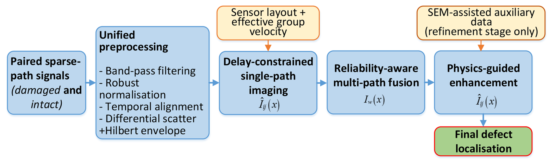
Figure 1Overview of the proposed sparse-path Lamb-wave imaging framework, including signal preprocessing, delay-constrained single-path imaging, reliability-aware fusion, and physics-guided enhancement. SEM-assisted auxiliary data are used only for refinement learning and validation.
As shown in Fig. 1, the framework consists of four stages. First, each damaged–intact signal pair is filtered, normalised, temporally aligned, and converted into a non-negative scattering-envelope feature. Second, each pathwise envelope is mapped into the inspection domain by delay-constrained elliptical backprojection. Third, the path images are fused using reliability weights derived from delay consistency, relative scattering amplitude, and envelope compactness. Fourth, the fused coarse image is refined by a lightweight enhancement network constrained by a soft physics prior. The SEM-assisted auxiliary data are used only for refinement learning and validation, whereas the measured sparse-path signals remain the basis of the physical front-end. Thus, the proposed pipeline is physics-first: learning is introduced only after a physically meaningful coarse image has been formed.
The reliability-weighted coarse image is formed by combining the normalised path images with their reliability weights:
After physics-guided refinement, the final defect estimate is obtained from the global maximum of the enhanced image:
Table 1Concise definitions of key terms used in the proposed framework.
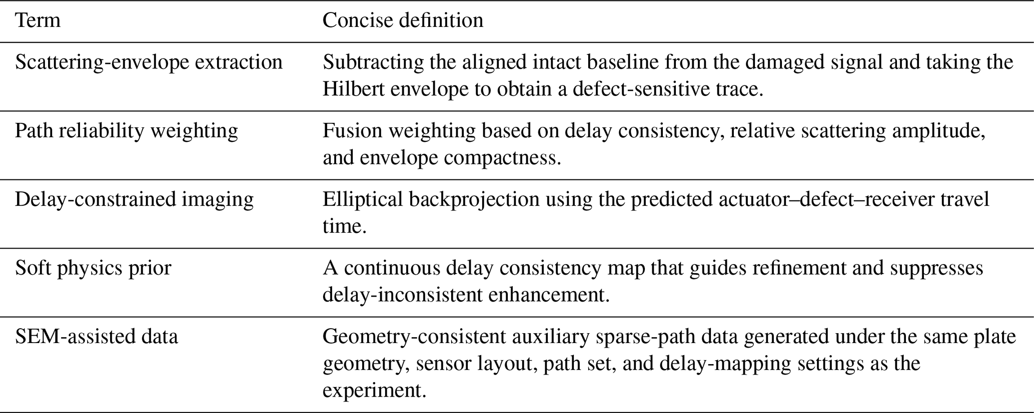
For clarity, Table 1 defines the key terms used throughout the proposed framework.
2.2 Signal preprocessing and scattering-envelope extraction
Because direct subtraction of damaged and intact traces is sensitive to gain variation and small trigger mismatches, all paths are processed using the same front-end before imaging. Each raw signal is first band-pass filtered in the 150–400 kHz range to retain the principal excitation band while suppressing low-frequency drift and high-frequency noise. The filtered traces are then normalised by a derivative-based scale estimate, which is less sensitive to slow baseline bias than direct amplitude normalisation:
Residual timing mismatch between the damaged and intact measurements is corrected by local cross-correlation:
which yields the aligned baseline . The defect-sensitive residual and its analytic envelope are then defined as
where ℋ[⋅] denotes the Hilbert transform. A short moving-average smoothing may be applied after Eq. (6) to suppress isolated spikes without materially shifting the peak position. The envelope eij(t) is used consistently in all subsequent imaging and reliability calculations.
2.3 Delay-constrained single-path elliptical imaging
For each actuator–sensor pair, a defect-scattered arrival constrains the candidate defect to an ellipse with the actuator and sensor as its foci. Let ri and rj denote the coordinates of the actuator and sensor for path (i,j), and let be a candidate point. The corresponding predicted delay is
where is the path-dependent effective group velocity used for delay mapping. Here, “effective” refers to the calibrated speed associated with the dominant imaged arrival; it absorbs practical effects such as finite bandwidth, modal mixture, and arrival-picking bias and should not be interpreted as intrinsic material anisotropy.
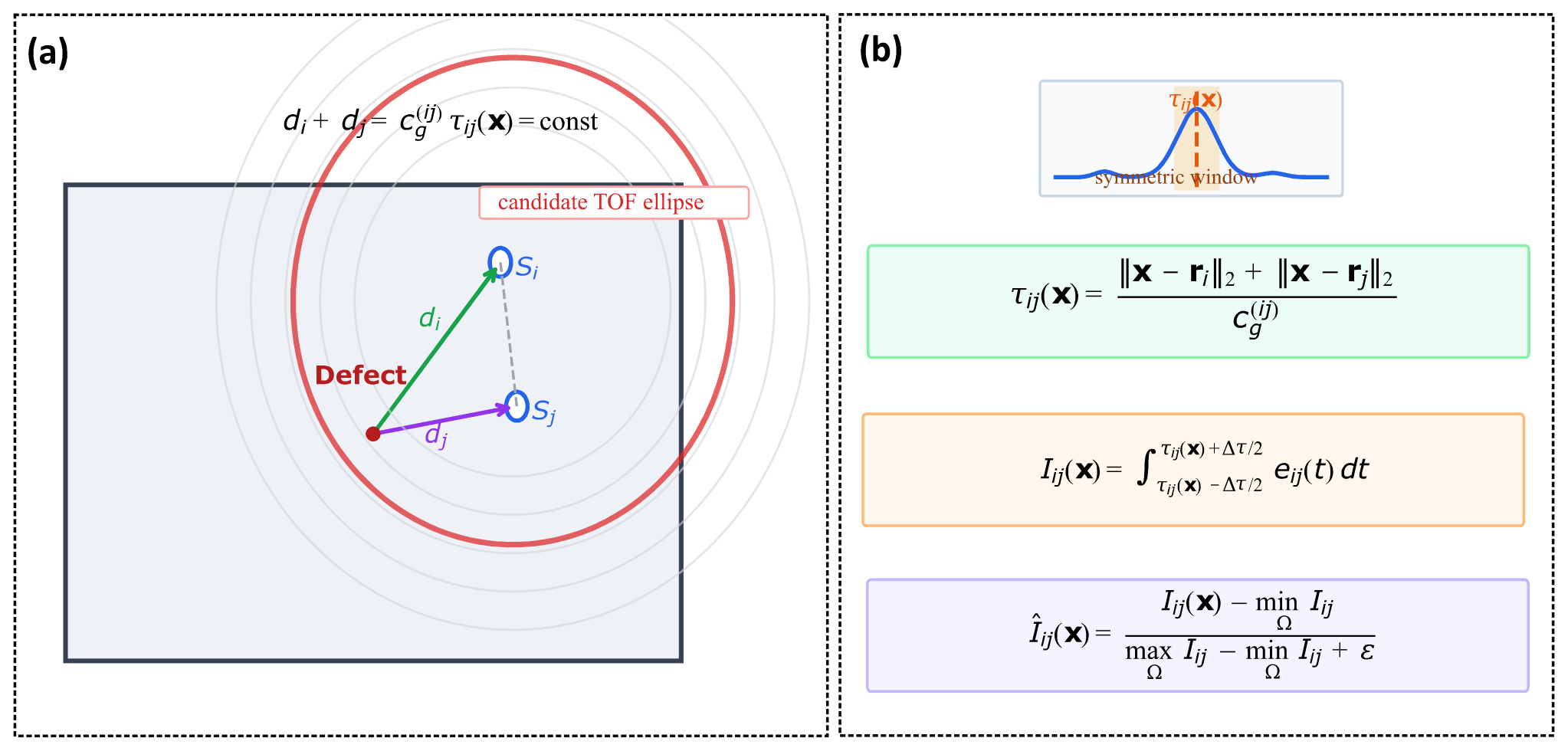
Figure 2Delay-constrained single-path elliptical imaging. A candidate point is evaluated by its predicted actuator–defect–receiver travel time, and the corresponding envelope energy is accumulated within a short temporal window.
Figure 2 illustrates this delay mapping. For one actuator–receiver path, all candidate points with the same total travel distance form an ellipse with the actuator and receiver as foci. Therefore, a single path does not uniquely determine the defect location; it only provides an admissible elliptical manifold.
Instead of assigning the envelope value at a single sample, a short symmetric integration window is used to improve robustness to arrival-picking errors and effective-velocity uncertainty:
where Δτ is the window width. The resulting path image is min–max normalised to suppress purely numerical scale differences between paths:
The single-path images already preserve the correct propagation geometry, but their quality is path dependent because the sparse network does not interrogate the defect region uniformly. This motivates the reliability-aware fusion stage.
2.4 Reliability-aware path weighting and multi-path fusion
A sparse-path image should not be formed by assuming that all paths are equally informative. In practice, some paths exhibit strong and temporally coherent defect-scattered arrivals, whereas others are weakened by poor coupling, unfavourable geometry, or diffuse responses. The proposed fusion strategy therefore uses a first-pass estimate followed by pathwise reliability assessment.
A coarse reference image is first obtained by equal-weight accumulation:
This first-pass location is used only to evaluate path consistency and is not taken as the final result.
For each path, let
denote the measured envelope peak time and the predicted delay at the coarse estimate, respectively. The time-of-flight mismatch is defined as
where is the temporal-consistency score.
To avoid relying on timing alone, two additional indicators are used: the peak envelope magnitude,
and the envelope compactness measured by temporal kurtosis,
where . Both Aij and κij are min–max normalised over the path set, yielding and .
The raw reliability score is then defined multiplicatively as
and the final fusion weights are
The reliability-weighted coarse image is therefore
Compared with uniform accumulation, Eq. (17) suppresses geometrically admissible but weak or inconsistent paths while retaining the complementarity of multi-path information.
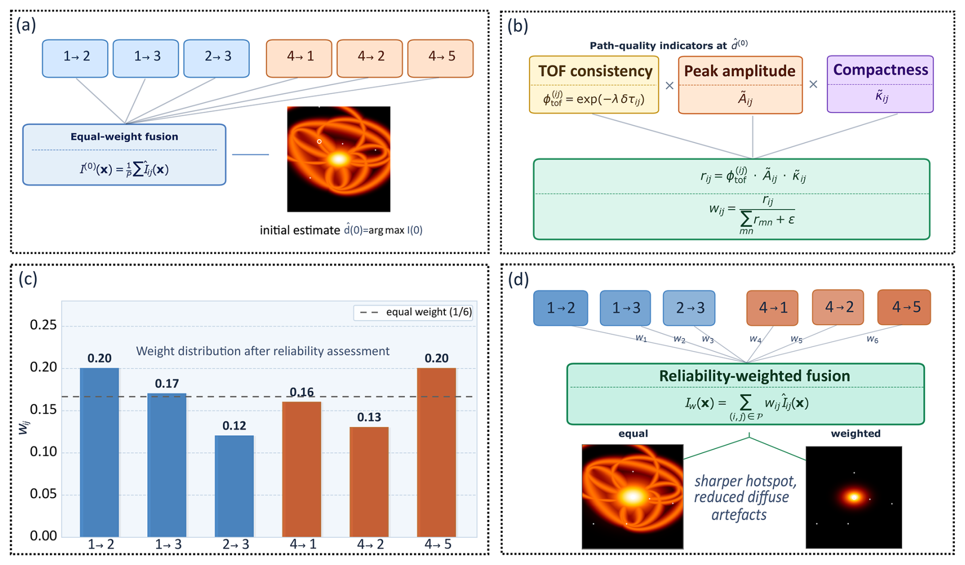
Figure 3Reliability-aware fusion: first-pass localisation, path quality indicators, normalised path weights, and weighted image formation.
2.5 Physics-guided lightweight enhancement network
Although reliability-aware fusion substantially improves the coarse image, residual artefacts may still remain because a sparse set of elliptical manifolds rarely intersects perfectly at a single pixel under realistic experimental uncertainty. A lightweight learning stage is therefore introduced, but its role is limited to refining the physically meaningful coarse image rather than performing end-to-end inversion from raw signals.
Let 𝒩θ(⋅) denote the trainable encoder–decoder. Its output is
where Mp(x) is a reliability-aware soft physics prior:
This prior highlights regions that remain compatible with the measured arrival times of the more reliable paths while softly penalising delay-inconsistent regions. Unlike a hard binary intersection mask, it remains stable when one or two paths are degraded and is therefore better suited to sparse-path measurements.
The network is trained to match the defect-centred target image G(x) defined in Sect. 3. A composite loss is adopted:
with
The reconstruction term preserves global fidelity, the focal term concentrates probability near the defect centre, and the physics-consistency term discourages enhancement in delay-inconsistent regions. This design keeps the learning stage compact, interpretable, and suitable for the present small-sample setting.
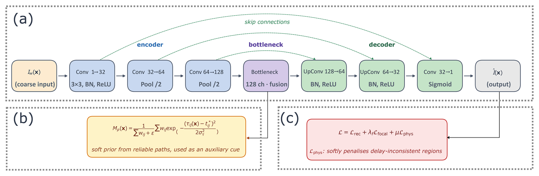
Figure 4Physics-guided refinement network with reliability-aware soft prior and composite loss.
Algorithmically, the proposed method follows a two-pass reliability procedure. An equal-weight image is first used only to obtain a coarse estimate ; this estimate is then used to evaluate pathwise delay consistency, relative envelope amplitude, and envelope compactness, from which the weights wij are calculated. The reliability-weighted image Iw and the soft-delay-consistency prior Mp are finally used as the physical input and auxiliary constraint of the lightweight refinement network so that learning acts as constrained image refinement rather than end-to-end inversion from raw signals.
2.6 Defect localisation and evaluation metrics
The final defect location is given by Eq. (3). Localisation accuracy is primarily measured by the Euclidean error
where d is the ground-truth defect location. We also report the success rate under a practical tolerance threshold eth:
Image fidelity is evaluated by the standard peak signal-to-noise ratio (PSNR) and structural similarity index (SSIM) between and G. To quantify how strongly the image energy is concentrated around the predicted defect region, we additionally use the side-lobe ratio:
where r0 is the radius of the main-lobe neighbourhood. Together, these metrics characterise both localisation accuracy and image quality and are used for the comparative analysis in Sect. 4.
This section summarises the experimental configuration, the construction of the paired sparse-path measurements, the SEM-assisted auxiliary datasets, the target label design, and the implementation settings used throughout the study. To keep the refinement stage physically grounded, the measured data and the auxiliary datasets share the same plate geometry, sensor topology, effective path set, and delay-mapping convention.
3.1 Specimen, defect, and sensor layout
The inspection target is a rectangular aluminium plate with dimensions of 300 mm×500 mm and a thickness of 3 mm. A plate-fixed Cartesian coordinate system is defined on the same 1 mm grid used for image reconstruction. The discrete in-plane coordinates are denoted by (x,y), with and . The reference defect in the measured dataset is a through-hole located at
The through-hole is used here as a controlled and repeatable representative defect and/or scattering source for quantitatively validating the sparse-path imaging chain. Extension from this compact through-hole scatterer to realistic crack morphologies is to be discussed in future work.
Five piezoelectric transducers are bonded to the plate surface and labelled as sensors 1–5. Their coordinates are
The effective sparse paths considered in this work are
corresponding to the shorthand path labels 12, 13, 23, 41, 42, and 45. This path set provides complementary coverage of the inspection region while remaining representative of a practically sparse sensing configuration. The same geometric definition is reused in the SEM-assisted auxiliary datasets so that the measured and auxiliary images remain directly comparable.
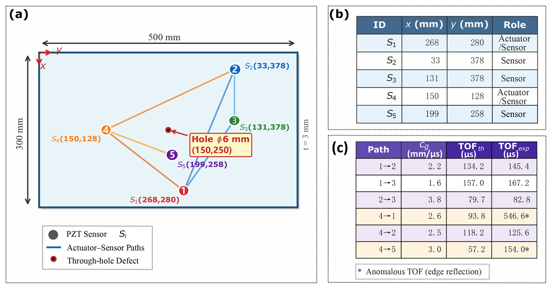
Figure 5Experimental specimen, sparse-path layout, and path parameters. (a) Geometry of the aluminium plate, through-hole defect, and piezoelectric transducer (PZT) arrangement in the plate-fixed coordinate system. (b) Effective actuator–sensor paths used for sparse-path imaging. (c) Path-dependent effective group velocities together with the corresponding theoretical and experimentally selected times of flight.
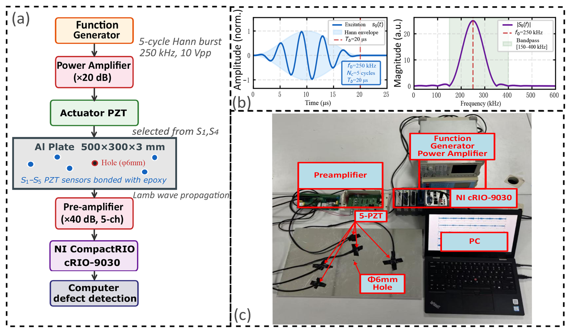
Figure 6Excitation and acquisition chain used to generate the sparse-path Lamb-wave measurements. (a) Experimental signal chain schematic. (b) Five-cycle Hann-windowed excitation signal and corresponding spectrum. (c) Photograph of the actual laboratory setup. Paired intact and damaged measurements are acquired under the same nominal excitation settings to enable differential scattering extraction in the subsequent preprocessing stage.
3.2 Data acquisition and paired-signal construction
The experimental data were acquired using the excitation and reception chain shown in Fig. 6. A five-cycle Hann-windowed tone burst with centre frequency 250 kHz was used throughout the experiments, consistently with the preprocessing assumptions in Sect. 2. For each effective path, paired recordings were obtained from two structural states: the damaged state containing the reference through-hole and the intact baseline state without the defect. This paired acquisition enables differential extraction of defect-sensitive scattering.
The measured signals were stored in nine CSV files: 23.csv, 23o.csv, 41o.csv, 42o.csv, 45.csv, 45o.csv, 123.csv, 132o.csv, and 421.csv. Each record contains 10 000 samples with a sampling interval of approximately Δt≈0.2 µs, corresponding to a record length of about 2 ms. The first column stores the time axis, whereas the signal channels of interest are taken from the third or fourth columns depending on the file structure. Any duplicated trailing columns are ignored during preprocessing.
The six pathwise signal pairs are formed as follows. Paths 12 and 13 are read from the multi-channel files 123.csv and 132o.csv; path 23 is read from 23.csv and 23o.csv; paths 41 and 42 are obtained from 421.csv, 41o.csv, and 42o.csv; and path 45 is constructed from 45.csv and 45o.csv. In the subsequent method description, these historical filenames are not propagated; each path is treated simply as a damaged–intact signal pair.
The raw paired traces also indicate why the unified preprocessing of Sect. 2.2 is required: the path amplitudes vary visibly across channels, and small timing mismatches remain between the damaged and intact recordings. Direct subtraction without normalisation and temporal alignment would therefore produce unstable residuals unrelated to genuine defect scattering.
3.3 SEM-assisted auxiliary dataset construction
Because the measured dataset is intentionally sparse and contains only a small number of experimental configurations, two SEM-assisted auxiliary datasets are introduced to support method development and lightweight enhancement learning. Both datasets use the same plate dimensions, sensor coordinates, effective path set, and path-dependent delay parameters as the experimental configuration. In the stored metadata, the generation method is recorded as SEM_Mie_v2; here it serves only as an identifier, whereas the main point is that the auxiliary data remain fully aligned with the experimental imaging geometry.
The defect locations in the SEM-assisted datasets are sampled within the same 300 mm×500 mm inspection domain and are represented by the stored hole_x and hole_y coordinates. Each defect is treated as a compact scattering source: for each actuator–receiver path, the dominant arrival is determined by the actuator–defect–receiver distance and the path-dependent effective group velocity. The resulting SEM-assisted images are therefore geometry-consistent surrogates for training and statistical assessment of the refinement stage rather than independent experimental evidence or a replacement for the measured Lamb-wave signals.
The first auxiliary dataset, denoted SEM-100, contains 100 cases with detailed descriptors. Its top-level entries include the sample list (dataset), defect-position array (positions), sensor layout (sensors), effective path set (paths), and path-dependent effective group velocities (cg). For each sample, the stored fields include id, hole_x, hole_y, IMAGE, scatter_envs, tofs, err, est_x, and est_y. This descriptor-rich dataset is therefore used primarily for method diagnosis, descriptor-level validation, and ablation-oriented analysis.
The second auxiliary dataset, denoted SEM-500, contains 500 cases and serves as the principal auxiliary training pool for the lightweight enhancement network. Its structure is similar at the dataset level, but each sample retains only id, hole_x, hole_y, IMAGE, and err. In other words, SEM-500 is image-centric and is therefore appropriate for refinement learning since the network operates on coarse images rather than on the original pathwise waveforms.
For both datasets, the stored coarse image IMAGE has size 300×500, matching the grid used in the measured-data imaging code. The stored path set and effective group velocities are
which are identical to those used in the delay mapping of Sect. 2.3. The auxiliary datasets are therefore not generic image corpora but rather are physically aligned surrogates of the same sparse-path imaging problem.
3.4 Ground-truth generation and label design
The refinement network of Sect. 2.5 is trained to regress a defect-centred target image rather than a one-pixel point label. This choice is motivated by the nature of sparse-path imaging: even when the defect coordinates are known exactly, the coarse hotspot is spatially extended and may exhibit localisation errors ranging from several millimetres to several tens of millimetres. A one-pixel target would therefore make the regression unnecessarily ill-conditioned.
The target image is defined as a Gaussian heatmap centred at the ground-truth defect position:
where σg controls the spatial spread. For the measured through-hole case, d is given by Eq. (25); for the SEM samples, the same role is played by the stored coordinates hole_x and hole_y. The label generation rule is therefore identical across the measured and auxiliary data sources.
A moderate Gaussian width is used so that training remains stable in the small-sample regime while preserving the localisation nature of the task. It also makes overlap-based evaluation more meaningful than it would be for a strictly one-pixel target. For metrics requiring binary support, the predicted image and the target image G(x) are thresholded at the same operating level. Because all labels are generated directly from known defect coordinates, the supervision is geometrically exact and does not rely on manual annotation.
3.5 Implementation details
All path images are reconstructed on a 300×500 grid with a spatial resolution of 1 mm per pixel. The experimental sampling interval is fixed at approximately Δt≈0.2 µs, and each path contains 10 000 samples. The same six sparse paths and the path-dependent effective group velocities in Eq. (28) are used consistently in both the experimental imaging code and the SEM-assisted auxiliary datasets.
The physical front-end comprises preprocessing, delay-constrained imaging, and reliability-aware fusion. The refinement stage is implemented as a three-level U-Net with base channel width C=8 and approximately 3×10⁴ trainable parameters. Training is performed on dataset_SEM_500.pkl using IMAGE as input and the Gaussian target map of Eq. (29) as supervision, whereas validation is conducted on dataset_SEM_100.pkl. The final checkpoint is selected at epoch 41 according to the minimum validation loss (0.0012).
The fixed implementation settings include the 150–400 kHz band-pass range, the sampling interval Δt≈0.2 µs, the six-path set in Eq. (27), the effective velocities in Eq. (28), and the U-Net width and checkpoint settings stated above.
All coordinates, labels, and evaluation metrics are expressed in the same plate-fixed coordinate system. The defect estimate from Eq. (3), the target map of Eq. (29), and the localisation error of Eq. (22) are therefore evaluated on the same 300×500 grid, eliminating coordinate conversion bias in the comparisons reported in Sect. 4.
This section evaluates the proposed framework from the signal level to the final localisation output. Following the data hierarchy defined in Sect. 3, the validation is divided into two layers. The physically interpretable front-end, including scattering-envelope extraction, single-path imaging, and reliability-aware fusion, is assessed directly on the measured sparse-path CSV data. The enhancement stage is then evaluated mainly on the descriptor-rich SEM-100 benchmark, with SEM-500 being used as the auxiliary training pool. This separation preserves physical grounding while still providing a statistically meaningful basis for assessing the refinement stage.
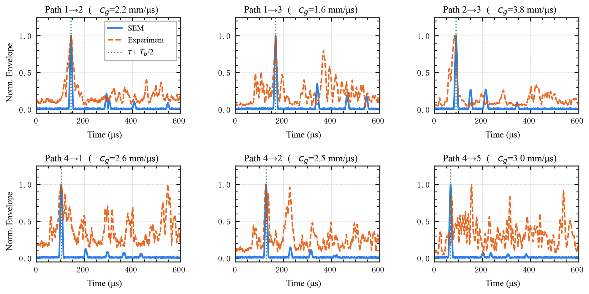
Figure 7Signal-level validation of the sparse-path scattering features. The six panels compare the normalised scatter envelopes obtained from SEM-assisted data and from the experimental measurements for all effective sparse paths. Despite the broader experimental clutter, the dominant early-arrival structure remains concentrated near the defect-sensitive delay region, supporting the use of delay-constrained imaging and reliability-aware path assessment.
4.1 Signal-level validation
We first verify whether the proposed preprocessing chain extracts defect-sensitive envelope features that remain physically meaningful across the six sparse paths. As shown in Fig. 7, the experimental envelopes are broader and more cluttered than their SEM-assisted counterparts, yet the dominant early-arrival structure remains concentrated near the defect-sensitive delay region. This agreement is sufficient for the purpose of the present method because the delay-constrained imaging and reliability assessment rely primarily on early defect-related arrivals rather than on the late-time tail of the record.
The practical implication is twofold. First, the preprocessing front-end is operating on physically interpretable scatter features rather than arbitrary subtraction residuals. Second, the increased late-time clutter in the measured signals explains why peak amplitude alone is not a reliable indicator of path quality, thereby motivating the combined use of temporal consistency and compactness in the weighting stage.
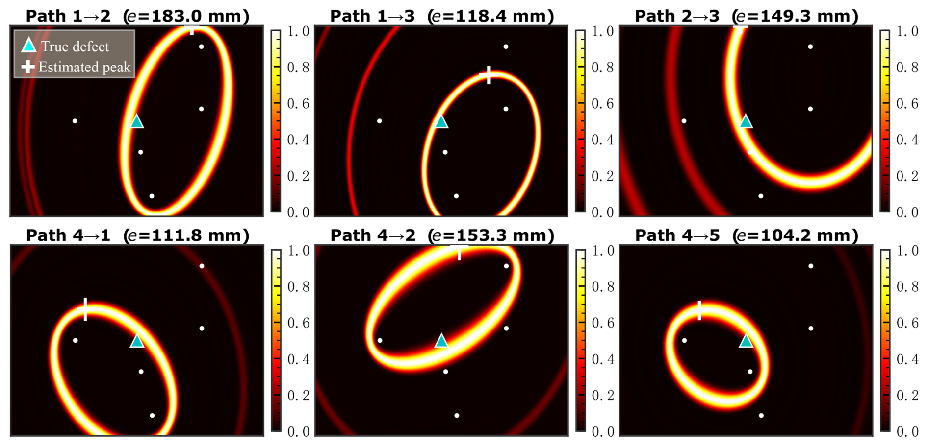
Figure 8Single-path delay-constrained imaging results obtained from the experimental sparse-path measurements. Each path produces an elliptical high-response structure consistent with the propagation geometry, but none of the six paths alone is sufficient for accurate localisation. The localisation error associated with each path is indicated above the corresponding panel.
4.2 Single-path imaging results
We next examine whether any single sparse path can localise the defect on its own. Figure 8 shows that each path produces an elliptical high-response structure consistent with the propagation geometry of Eq. (7), but none of the six paths yields accurate localisation by itself. The annotated localisation errors range from 104.2 to 183.0 mm, with even the best case, path 4→5, remaining far outside a practically acceptable tolerance.
This result confirms that the sparse-path problem is genuinely underdetermined at the single-path level. It also clarifies why simple geometric admissibility is insufficient: some paths generate compact ellipses that pass close to the true defect, whereas others produce broader or more weakly informative manifolds. Accordingly, the purpose of the subsequent fusion stage is not merely to accumulate responses but to combine geometrically complementary paths while limiting the influence of those that are only marginally informative.
Figure 8 therefore provides a concrete case study of sparse-path ambiguity. The true defect can lie close to an admissible elliptical response, but the maximum response along that ellipse may still be displaced far from the true location. The large single-path errors are thus not caused by one exceptionally poor channel; rather, they reflect the non-uniqueness of single-path delay constraints. This is why the proposed framework first combines complementary path geometries and then uses reliability weighting to suppress paths with weak or inconsistent scattering evidence.
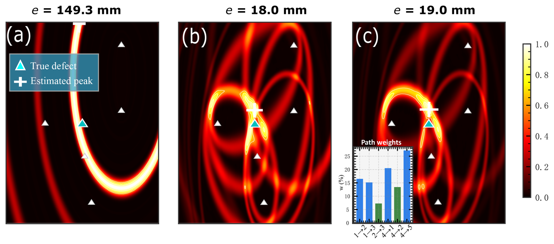
Figure 9Fusion comparison on the experimental reference case. (a) Best single-path image. (b) Uniform fusion of all six sparse paths. (c) Reliability-weighted fusion with the corresponding path weights shown in the inset. The triangle and cross indicate the true defect location and the estimated peak, respectively.
4.3 Reliability-weighted fusion results
Figure 9 compares three representative front-end outputs on the experimental reference case: the best single-path image, the uniform fusion of all six paths, and the proposed reliability-weighted fusion. As expected from the previous subsection, the best single-path image remains grossly inaccurate, whereas both multi-path fusion strategies collapse the dispersed ellipse families into a compact candidate region near the true defect and reduce the localisation error to the order of 20 mm. For this specific case, the equal-weight and reliability-weighted fused images yield similar localisation errors (18.0 and 19.0 mm, respectively). This observation should not be interpreted as evidence against the weighting strategy because peak error alone does not fully describe coarse-image quality. A simple half-maximum area count, defined as the number of pixels with intensity not lower than 50 % of the image maximum, is smaller for the reliability-weighted image than for the equal-weight image ( vs. 7.0×103 pixels). This indicates a more compact hotspot and reduced diffuse background. Thus, the role of reliability-aware fusion is to provide a physically more selective and better-conditioned coarse representation for the subsequent refinement stage rather than to guarantee a lower peak error in every individual coarse-stage instance.
The inset path weights further reinforce the methodological point made in Sect. 2.4: the six sparse paths should not be regarded to be equally trustworthy. Reliability-aware fusion preserves the geometric complementarity of multi-path imaging while suppressing the contribution of paths whose envelopes are temporally inconsistent or morphologically diffuse. The resulting coarse image is therefore more physically credible, even when its peak error is numerically close to that of uniform fusion in a particular case.
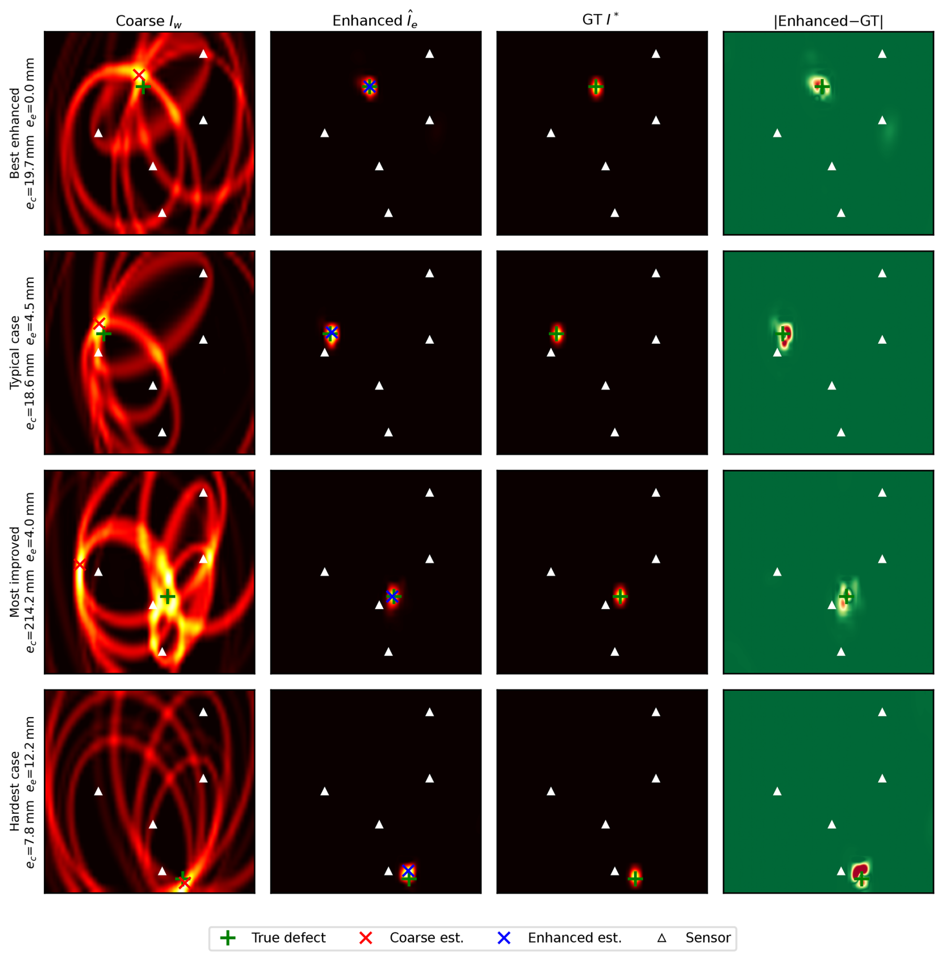
Figure 10Representative refinement examples from the SEM-assisted validation set. For each case, the coarse image is compared with the corresponding enhanced output, the difference map, and the ground-truth defect location. The refinement stage primarily suppresses diffuse ellipse traces and contracts the response into a compact defect-centred hotspot.
4.4 Enhancement performance
Because only one measured defect instance is available experimentally, the enhancement stage is evaluated primarily on the physically aligned SEM-100 benchmark, while the network is trained on SEM-500. This setting allows the refinement stage to be assessed over a sufficiently broad defect set without disconnecting it from the sparse-path imaging geometry defined in Sect. 3.
Representative examples are shown in Fig. 10. In most cases, the coarse image Iw already places the dominant response in the correct neighbourhood, but the hotspot remains broadened by intersecting ellipse branches and diffuse side lobes. After refinement, the response contracts into a more compact defect-centred region, and the surrounding clutter is markedly reduced. The difference maps indicate that the network acts mainly as a structured suppressor of diffuse artefacts rather than as an unconstrained image generator.
At the benchmark level, the enhancement stage reduces the mean localisation error from 19.0 mm for the reliability-weighted coarse image to 4.8 mm after refinement. The gain is therefore not a marginal visual improvement, but a substantial final-stage regularisation effect that sharpens the peak, improves concentration, and increases consistency across cases.
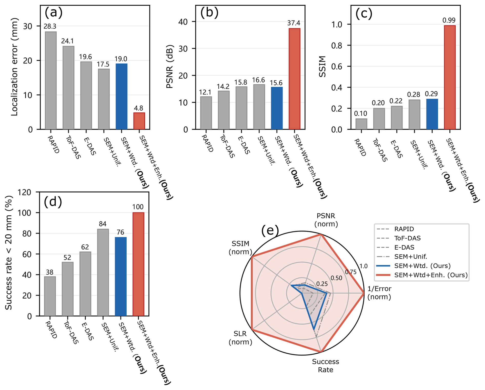
Figure 11Multi-metric comparison with baseline methods. (a) Mean localisation error. (b) Peak signal-to-noise ratio (PSNR). (c) Structural similarity index (SSIM). (d) Success rate within a 20 mm tolerance. (e) Radar-chart summary of the normalised multi-metric performance, including , PSNR, SSIM, side-lobe ratio (SLR), and success rate. The proposed reliability-weighted and enhanced framework achieves the best overall trade-off between localisation accuracy and image quality among the compared methods.
4.5 Quantitative comparison
The overall effectiveness of the proposed framework is summarised in Fig. 11 using multiple criteria, including localisation error, PSNR, SSIM, success rate within 20 mm, and the radar chart summary of normalised performance. This multi-metric view is necessary because sparse-path Lamb-wave imaging should be judged not only by peak position but also by the concentration and structural credibility of the reconstructed image.
Two internal reference variants are especially informative: the coarse uniform-fusion image (SEM+Unif.) and the reliability-weighted coarse image (SEM+Wtd. (ours)). The former represents the physical front-end without reliability screening, whereas the latter provides the coarse representation used by the subsequent refinement stage. Relative to the reliability-weighted coarse image, the full framework reduces the mean localisation error from 19.0 to 4.8 mm and simultaneously improves the image quality metrics, consistently with the qualitative behaviour observed in Fig. 10. The contribution of the enhancement stage is therefore not merely visual sharpening but a substantial final-stage regularisation effect that improves both localisation accuracy and image fidelity.
At the same time, Fig. 11 should be interpreted carefully. Figure 9 reports a single measured reference case, whereas Fig. 11 summarises benchmark-level statistics over the SEM-100 dataset. The two comparisons therefore serve different purposes and should not be interpreted as numerically equivalent views of the same experiment. In particular, the benefit of reliability weighting should be understood primarily in terms of coarse-image conditioning for enhancement rather than as a universally superior standalone fusion rule under every coarse-stage metric.
Figure 11 also includes literature-level reference baselines such as RAPID, ToF-DAS, and E-DAS. These comparisons are intended as contextual benchmarks rather than strict like-for-like re-implementations under identical raw-data conditions. Even under that conservative interpretation, the proposed reliability-weighted and enhanced framework achieves the strongest overall trade-off, combining the lowest mean localisation error with the most favourable overall image-quality profile.
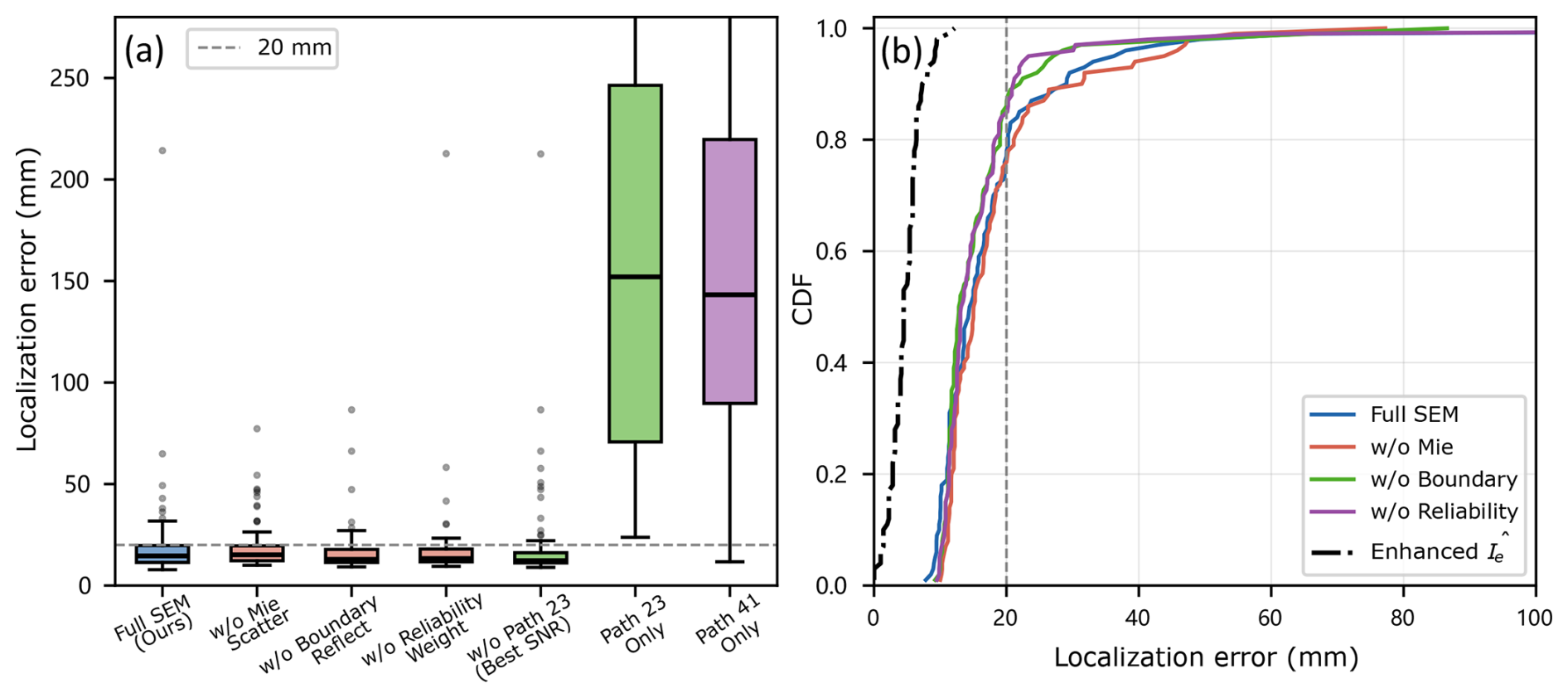
Figure 12Ablation study of the proposed framework. (a) Localisation-error distributions under different model reductions; the dashed line marks the 20 mm tolerance. (b) Corresponding localisation-error cumulative distribution functions (CDFs) for representative ablation settings and the enhanced output . The full framework yields the most compact and stable localisation performance.
4.6 Ablation study
The ablation results in Fig. 12 identify which components are genuinely necessary. The full framework yields the most compact error distribution and the strongest cumulative behaviour, whereas removing any major component broadens the distribution and reduces localisation stability.
The largest degradation occurs when the system is reduced to a single path. The two single-path-only variants show very broad error distributions and large outliers exceeding 200 mm, which is fully consistent with the experimental observation in Fig. 8 and confirms that sparse-path localisation is fundamentally a multi-path problem.
The intermediate ablations are more mechanistically informative. Removing the Mie-scattering component broadens the distribution and lowers the success rate within 20 mm to 75 %, indicating that physically meaningful scatter formation remains important even when the later enhancement stage is present. Removing reliability weighting also degrades performance, though less severely, suggesting that the weighting stage primarily stabilises the coarse image and mitigates occasional path conflicts.
A notable detail is that removing path 2→3 does not degrade the cumulative distribution and even yields a slight improvement in this benchmark. This does not imply that the path is useless; rather, it shows that a geometrically admissible path can still become locally counterproductive when its scatter response is less consistent with the dominant path family. The ablation therefore supports the central premise of the method: path usefulness must be evaluated from the measured response and not from geometry alone.
4.7 Robustness analysis
A practically useful Lamb-wave imaging method must remain stable under moderate noise, imperfect path availability, and uncertainty in the effective group velocity. To keep the robustness analysis compact, representative perturbation tests on the SEM-100 benchmark were summarised by localisation error and the success rate within 20 mm. The mean error changed from 4.8 mm in the nominal setting to approximately 5.1/6.3 mm under 30/20 dB additive noise, to 5.7/9.1 mm when retaining five or four paths, and to 5.5/8.6 mm under −5 % and +5 % group velocity bias; the corresponding success rates remained in the range of 90 %–100 %. The trends remain path dependent: path removal weakens ellipse intersection constraints, and positive velocity bias is more harmful because it compresses the predicted ellipse family inward. These results indicate robust routine performance while identifying path availability and velocity calibration as the main practical sensitivities.
4.8 Discussion
Several conclusions follow from the above results. First, the signal-level agreement between the SEM-assisted and experimental envelopes, although not perfect, is sufficiently strong in the defect-sensitive early-arrival region to support the delay-based mapping and the reliability indicators used in the present framework. Second, the fusion and enhancement stages play distinct roles: the reliability-aware fusion stage converts the gross geometric ambiguity of the sparse paths into a physically meaningful coarse hotspot, whereas the refinement stage sharpens that hotspot and suppresses diffuse clutter. Third, the remaining larger errors are not random but tend to occur near sensors or in regions of weaker angular coverage, where local delay ambiguity and direct-wave contamination remain more difficult to resolve.
The results also clarify how the reliability-aware stage should be interpreted. Its principal value is not to guarantee uniformly lower coarse-stage error than equal-weight fusion in every individual case but to provide a more selective and physically better-conditioned representation for refinement. This distinction is important for understanding the relationship between the single experimental illustration of Fig. 9 and the benchmark-level statistics of Fig. 11. The final performance gain emerges from the interaction between a physically grounded front-end and a constrained refinement stage rather than from any one component acting in isolation.
The present work should therefore be interpreted as a physically grounded sparse-path imaging methodology with experimentally anchored validation. The controlled experimental specimen is a through-hole case, while the statistical evaluation of the enhancement stage is carried out mainly on geometrically aligned SEM-assisted data. Accordingly, the present study demonstrates the validity of the sparse-path imaging and refinement pipeline rather than an exhaustive validation across the full spectrum of crack morphologies encountered in service. Broader experimental verification on richer crack families and more diverse structural conditions remains an important next step.
This study has presented a reliability-aware physics-guided framework for sparse-path Lamb-wave defect imaging under small-sample conditions. The proposed method combines unified preprocessing and scattering-envelope extraction, delay-constrained single-path elliptical imaging, reliability-aware multi-path fusion, and lightweight image refinement under a soft physics prior. Rather than relying on purely geometric equal-weight fusion or unconstrained end-to-end learning, the framework preserves the physical structure of guided-wave propagation while using learning only as a constrained refinement stage.
The results demonstrate that the method is effective at both the front-end and image levels. The measured paired sparse-path signals show that the preprocessing chain extracts defect-sensitive scattering envelopes that remain concentrated near the physically meaningful arrival region. Single-path imaging is strongly underdetermined, with localisation errors exceeding 100 mm for all six sparse paths, whereas multi-path fusion reduces this gross ambiguity to a coarse defect-centred hotspot in the tens-of-millimetres range. Within this front-end, the reliability-aware formulation provides a more selective and physically better-conditioned coarse representation for the subsequent enhancement stage. On the physically aligned SEM-assisted benchmark, the refinement stage further sharpens this coarse image into a compact defect-centred map, reducing the mean localisation error from 19.0 to 4.8 mm while also improving image quality.
At the same time, the scope of the present study should be stated clearly. The experimental validation is based on a controlled through-hole specimen, and the statistical assessment of the refinement stage is conducted mainly using SEM-assisted data rather than through a large multi-defect experimental campaign. The present contribution should therefore be understood as a physically grounded sparse-path imaging methodology with experimentally anchored validation. Future work will extend the measured benchmark from the present representative through-hole defect to richer crack morphologies, multi-defect cases, and more diverse structural conditions and will further systematise robustness-aware refinement under path dropout and parameter uncertainty.
The data supporting the findings of this study are not publicly available due to confidentiality and institutional restrictions related to ongoing research projects. However, the data may be made available from the corresponding author upon reasonable request and with permission from the relevant parties. The code used for data processing and analysis is available from the corresponding author upon reasonable request.
TY: conceptualisation, methodology, software, investigation, formal analysis, visualisation, writing (original draft). PL: methodology, resources, validation, writing (review and editing), supervision. Both authors contributed equally to this work and approved the final paper.
The contact author has declared that neither of the authors has any competing interests.
Publisher's note: Copernicus Publications remains neutral with regard to jurisdictional claims made in the text, published maps, institutional affiliations, or any other geographical representation in this paper. The authors bear the ultimate responsibility for providing appropriate place names. Views expressed in the text are those of the authors and do not necessarily reflect the views of the publisher.
The authors thank the editor and the anonymous reviewers for their constructive comments, which helped improve the clarity of the paper.
This research has been supported by the Natural Science Foundation of Zhejiang Province (grant no. LTGG24F030001). Ting You acknowledges support from the China Scholarship Council (grant no. 202408330447).
This paper was edited by Pengyuan Zhao and reviewed by two anonymous referees.
Barzegar, M., Moradi Cherati, S., Pasadas, D. J., Pernechele, C., Ribeiro, A. L., and Ramos, H. G.: Baseline-free damage imaging of CFRP lap joints using K-means clustering of guided wave signals, Mech. Syst. Signal Pr., 229, 112562, https://doi.org/10.1016/j.ymssp.2025.112562, 2025. a, b
Chen, C.-D., Shen, Y.-J., Chou, P.-Y., and Wang, P.-H.: A Lamb-wave based SHM for multi-damage localizations in large composite plates by using piezoelectric transducer array, Smart Mater. Struct., 33, 045028, https://doi.org/10.1088/1361-665X/ad3160, 2024. a
Gao, Y., Sun, L., Song, R., Peng, C., Wu, X., Wei, J., Jiang, M., Sui, Q., and Zhang, L.: Damage localization in composite structures based on Lamb wave and modular artificial neural network, Sensor. Actuat. A-Phys., 377, 115644, https://doi.org/10.1016/j.sna.2024.115644, 2024. a
Gonzalez-Jimenez, A., Lomazzi, L., Junges, R., Giglio, M., Manes, A., and Cadini, F.: Enhancing Lamb wave-based damage diagnosis in composite materials using a pseudo-damage boosted convolutional neural network approach, Struct. Health Monit., 23, 1514–1529, https://doi.org/10.1177/14759217231189972, 2024. a
Huang, L., Luo, Z., Zeng, L., and Lin, J.: Detection and localization of corrosion using the combination information of multiple Lamb wave modes, Ultrasonics, 138, 107246, https://doi.org/10.1016/j.ultras.2024.107246, 2024. a
Khurjekar, I. D. and Harley, J. B.: Reliability assessment of guided wave damage localization with deep learning uncertainty quantification methods, NDT & E Int., 144, 103099, https://doi.org/10.1016/j.ndteint.2024.103099, 2024. a, b
Li, X., Liu, L., Xu, H., Hu, Z., Xiang, Y., and Xuan, F.-Z.: Lamb wave phased array imaging based on phase-amplitude compounding algorithm, Mech. Syst. Signal Pr., 205, 110882, https://doi.org/10.1016/j.ymssp.2023.110882, 2023. a
Luo, K., Chen, L., Chen, Y., Ye, L., and Yu, S.: An ultrasonic Lamb wave-based non-linear exponential RAPID method for delamination detection in composites, Compos. Struct., 352, 118701, https://doi.org/10.1016/j.compstruct.2024.118701, 2025. a, b
Philibert, M., Yao, K., Gresil, M., and Soutis, C.: Lamb waves-based technologies for structural health monitoring of composite structures for aircraft applications, European Journal of Materials, 2, 436–474, https://doi.org/10.1080/26889277.2022.2094839, 2022. a
Segers, J., Hedayatrasa, S., Poelman, G., Van Paepegem, W., and Kersemans, M.: Robust and baseline-free full-field defect detection in complex composite parts through weighted broadband energy mapping of mode-removed guided waves, Mech. Syst. Signal Pr., 151, 107360, https://doi.org/10.1016/j.ymssp.2020.107360, 2021. a, b
Segers, J., Hedayatrasa, S., Poelman, G., Van Paepegem, W., and Kersemans, M.: Self-reference broadband local wavenumber estimation (SRB-LWE) for defect assessment in composites, Mech. Syst. Signal Pr., 163, 108142, https://doi.org/10.1016/j.ymssp.2021.108142, 2022. a, b
Wang, D., Wang, X., Chen, S., Li, J., Liang, L., and Liu, Y.: Joint learning of sparse and limited-view guided waves signals for feature reconstruction and imaging, Ultrasonics, 137, 107200, https://doi.org/10.1016/j.ultras.2023.107200, 2024. a, b
Wang, X., Lin, M., Li, J., Tong, J., Huang, X., Liang, L., Fan, Z., and Liu, Y.: Ultrasonic guided wave imaging with deep learning: Applications in corrosion mapping, Mech. Syst. Signal Pr., 169, 108761, https://doi.org/10.1016/j.ymssp.2021.108761, 2022. a, b
Wu, J., Xu, X., Liu, C., Deng, C., and Shao, X.: Lamb wave-based damage detection of composite structures using deep convolutional neural network and continuous wavelet transform, Compos. Struct., 276, 114590, https://doi.org/10.1016/j.compstruct.2021.114590, 2021. a
Wu, W., Malik, M. K., Cantero-Chinchilla, S., Lawrie, T. M., Yan, W. J., Tanner, G., Remenyte-Prescott, R., and Chronopoulos, D.: Guided waves-based damage identification in plates through an inverse Bayesian process, Ultrasonics, 125, 106773, https://doi.org/10.1016/j.ultras.2022.106773, 2022. a
Xu, C., Peng, L., and Deng, M.: Phased array imaging for damage localization using multi-narrowband Lamb waves, Mech. Syst. Signal Pr., 190, 110134, https://doi.org/10.1016/j.ymssp.2023.110134, 2023a. a
Xu, H., Liu, L., Li, X., Xiang, Y., and Xuan, F.-Z.: Wavefield imaging of nonlinear ultrasonic Lamb waves for visualizing fatigue micro-cracks, Ultrasonics, 138, 107214, https://doi.org/10.1016/j.ultras.2023.107214, 2024a. a, b
Xu, H., Liu, L., Xu, J., Xiang, Y., and Xuan, F.-Z.: Deep learning enables nonlinear Lamb waves for precise location of fatigue crack, Struct. Health Monit., 23, 77–93, https://doi.org/10.1177/14759217231167076, 2024b. a
Xu, J., Zhu, W., Qiu, X., and Xiang, Y.: A novel baseline-free method for damage localization using guided waves based on hyperbola imaging algorithm, Sensors, 23, 2050, https://doi.org/10.3390/s23042050, 2023b. a
Xue, C., Zhou, T., Li, J., and Li, B.: Graph Laplacian-regularized pseudo-force sparse reconstruction imaging for damage in complex composite structures, Mech. Syst. Signal Pr., 238, 113178, https://doi.org/10.1016/j.ymssp.2025.113178, 2025a. a, b
Xue, C., Zhou, T., Zhang, Z., and Li, B.: Pseudo-force-based sparse reconstruction damage imaging with guided waves, Measurement, 251, 117151, https://doi.org/10.1016/j.measurement.2025.117151, 2025b. a
Yang, Z., Yang, H., Tian, T., Deng, D., Hu, M., Ma, J., Gao, D., Zhang, J., Ma, S., Yang, L., Xu, H., and Wu, Z.: A review on guided-ultrasonic-wave-based structural health monitoring: From fundamental theory to machine learning techniques, Ultrasonics, 133, 107014, https://doi.org/10.1016/j.ultras.2023.107014, 2023. a
Yu, H., Lv, M., Hu, B., Zhang, Y., and Zhao, P.: Review article: A review of control technologies for soft robots: from structural design to intelligent control, Mech. Sci., 17, 313–332, https://doi.org/10.5194/ms-17-313-2026, 2026. a
Yu, Y., Liu, X., Wang, Y., Wang, Y., and Qing, X.: Lamb wave-based damage imaging of CFRP composite structures using autoencoder and delay-and-sum, Compos. Struct., 303, 116263, https://doi.org/10.1016/j.compstruct.2022.116263, 2023. a, b
Zeng, X., Liu, X., Yan, J., Yu, Y., Zhao, B., and Qing, X.: Lamb wave-based damage localization and quantification algorithms for CFRP composite structures, Compos. Struct., 295, 115849, https://doi.org/10.1016/j.compstruct.2022.115849, 2022. a
Zeng, X., Yan, J., Liu, Q., Zhao, B., and Qing, X.: Multi-crack damage identification and quantification using Lamb wave-based structural health monitoring, Thin Wall. Struct., 208, 112782, https://doi.org/10.1016/j.tws.2024.112782, 2025. a, b
Zhang, H., Wang, F., Lin, J., and Hua, J.: Lamb wave-based damage assessment for composite laminates using a deep learning approach, Ultrasonics, 141, 107333, https://doi.org/10.1016/j.ultras.2024.107333, 2024a. a, b
Zhang, Z., Zeng, L., and Zhang, N.: Damage imaging using multipath-scattered Lamb waves under a sparse reconstruction framework, Struct. Health Monit., 23, 2013–2025, https://doi.org/10.1177/14759217231203241, 2024b. a, b
Zhang, Z., Li, B., Xue, C., Wang, Y., and Zhang, Y.: Guided wave multi-frequency damage localization method in variable-thickness structures by one pair of sensors based on frequency-dependent velocity anisotropy, Ultrasonics, 145, 107468, https://doi.org/10.1016/j.ultras.2024.107468, 2025. a
Zhao, P., Wu, C., and Li, Y.: Design and application of solar sailing: A review on key technologies, Chinese J. Aeronaut., 36, 125–144, https://doi.org/10.1016/j.cja.2022.11.002, 2023. a
Zhu, H., Sharif Khodaei, Z., and Aliabadi, F. M. H.: Appraisal of linear baseline-free techniques for guided wave based structural health monitoring, Ultrasonics, 144, 107445, https://doi.org/10.1016/j.ultras.2024.107445, 2024. a