the Creative Commons Attribution 4.0 License.
the Creative Commons Attribution 4.0 License.
 | 16 Apr 2026
A reconfigurable seven-link multi-mode external-fixation system for improving emergency limb fracture stabilization efficiency
Cuizhi Fei
Zongqi Jiao
Qiaoling Meng
Bangke Zhang
Xuhua Lu
The traditional external fixation has problems such as a single fixed dimension, limited application range, long fixation time, and heavy weight. A single-function external fixation is unable to meet the various needs of fracture fixation in scenarios involving a large number of injured patients. This paper proposes a reconfigurable-configuration comprehensive method based on a seven-link mechanism. A new type of reconfigurable external-fixation frame with multi-dimensional, multi-posture, and multi-fracture scenario applicability is formed, able to achieve rapid and stable external fixation for fractures in the femur, tibia, elbow joint, knee joint, and ankle joint. A reconfigurable mechanism configuration design is proposed based on the comprehensive configuration of the seven-link mechanism and the analysis of the working space. Human–fixator coupled biomechanical model is established, and the mechanical and stability performance of fractures under five reconfigurable configurations are analysed based on finite-element analysis. Compared with the corresponding single-function external-fixation frame in terms of performance, mechanics, and fixation time, a comparative experiment was finally conducted based on the cross-knee joint of dogs for verification. The results confirmed that the external fixation has the advantages of light weight, stable structure, multiple dimensions, multiple postures, and applicability to various fracture scenarios in addition to the fact that it shortens the fixation time significantly (< 10 min). Compared with other unilateral external fixation, the new external fixation is lighter in weight (weighing 950 g), with a fracture displacement of 3 mm, and the load is 274.2 N, the stiffness is 95.2 N mm−1, and the stability is higher than that of the unilateral external fixator (237.63 N, 72.4 N mm−1). When the relative rotation angle of the fracture end reaches 30°, the torque is 14.66 N m. This external fixation can be widely used in temporary fracture fixation in emergency medical scenarios.
- Article
(3063 KB) - Full-text XML
- BibTeX
- EndNote


Fractures of the limbs are one of the most common and severe types of injuries in trauma orthopaedics. Their rapid treatment and stable fixation directly affect the pain control of the injured, the prevention of further injuries, and the subsequent treatment process (Medici et al., 2023). In the treatment of multiple injuries, fractures of the limbs caused by high-energy traumas such as traffic accidents and falls from heights have a relatively high incidence (Almigdad et al., 2022; Hoogervorst et al., 2020; Weil and Mosheiff, 2011). In military war injury treatment, limb injuries have accounted for a major proportion for a long time. Modern battlefield statistics show that limb injuries account for up to 76 %–90 % of war injuries, and about 40 % of them are severe limb fractures (Belmont et al., 2013; Stern et al., 2019; Yun et al., 2016). In addition, in disaster rescue scenarios such as earthquakes, building collapses and crush impacts can cause a large number of fracture casualties in a short period of time (Sever et al., 2024; Wolfson et al., 2016). The common characteristics of these scenarios are a complex environment, scarce medical resources, and difficult transportation of the injured. Therefore, there is a higher demand for emergency fixation equipment: it should be portable, with a wide range of applications, fast assembly speed, and reliable fixation, in order to meet the urgent need for treating a large number of injured people within a short period of time (Bliven et al., 2019).
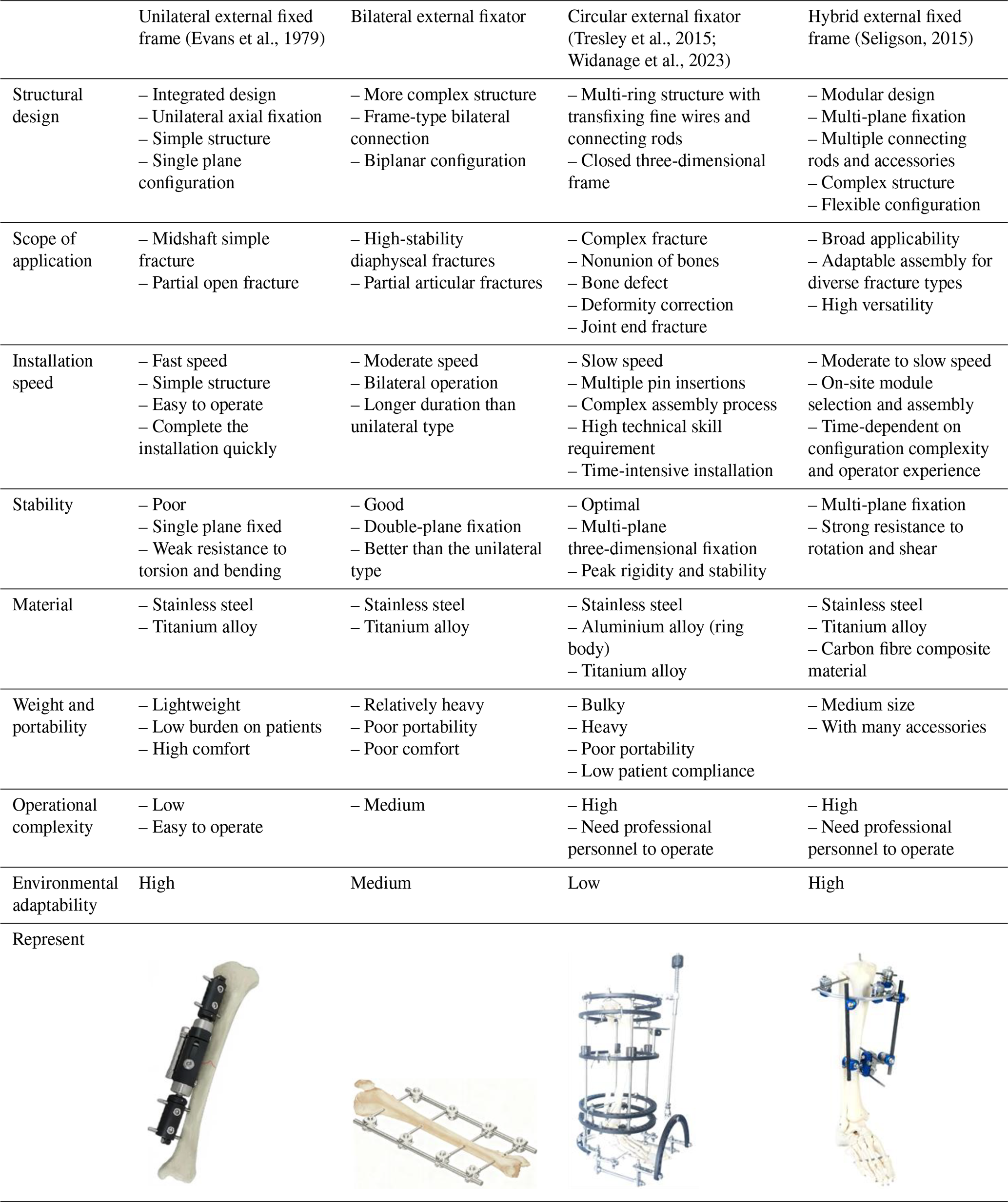
The external-fixation technique, due to its advantages such as its being minimally invasive, its rapidity, and the ability to be implemented on site, plays an irreplaceable role in the aforementioned complex scenarios. It can achieve fracture stabilization in the early stage, limit abnormal movement of the fracture ends, reduce secondary soft tissue injuries, and secure time for subsequent transfer and staged treatment. Additionally, its open structure makes it convenient for observing the wound, changing the dressing, and conducting the subsequent surgical procedures (Bull et al., 2025; Fernando et al., 2021). After years of development, clinical external fixations have formed several mature configurations, mainly including unilateral, bilateral, circular (Ilizarov type), and mixed basic forms. Different configurations have significant differences in load-bearing paths, bending and torsion resistance, applicable areas, and operational complexity (see Table 1). However, the existing external fixations often have a single fixation dimension and limited application scope, and their specialized designs are often unsuitable for multi-site fractures or joint fixation requirements, as well as emergency tasks with significant variations in the patient's body type. In such cases, it is often necessary to replace the equipment or to repeatedly adjust, which can result in restricted applicability, complex procedures, and increased time consumption. Therefore, for tasks with high timeliness such as large-scale casualties and battlefield rescue, how to achieve a new type of reconfigurable external-fixation framework with multiple dimensions and applicability to various fracture scenarios while ensuring mechanical stability becomes a key challenge in the development of the external-fixation system.
Addressing this challenge necessitates the integration of advanced reconfigurable mechanism designs. While current research in reconfigurable mechanisms and multi-modal robots has enabled robotic systems with remarkable adaptability to diverse environments and tasks (Liu et al., 2022; Wang et al., 2026), their application within the specific domain of external-fixation systems remains largely unexplored.
The innovation of this study lies in that it does not simply optimize the dimensions or local structure of a conventional external fixator but also introduces a reconfigurable mechanism concept into the design of an orthopaedic external-fixation system. Based on a seven-link topological framework, the proposed device integrates multiple fixation modes into a unified structural platform so that one system can adapt to different fracture sites and fixation postures. In this way, the proposed design differs from traditional task-specific external fixators and provides a new solution that combines multi-dimensional adaptability, multi-scenario applicability, and mechanical stability for emergency fracture fixation.
Reconfigurable and multi-mode mechanisms have been widely investigated in robotics, deployable structures, and adaptive mechanical systems because of their capability to improve task versatility and environmental adaptability. By changing configuration, topology, or motion mode, a single mechanism can perform different functions or adapt to different working conditions. However, in the field of orthopaedic external fixation, the application of reconfigurable mechanism theory remains relatively underexplored. Most currently available external-fixation devices are still designed for specific anatomical regions or relatively single fixation tasks, and few studies have systematically explored the use of a single reconfigurable mechanism to rapidly adapt to multiple fracture sites, fixation postures, and body size differences. Therefore, introducing reconfigurable mechanism synthesis into external-fixation system design is meaningful not only for improving clinical applicability in emergency rescue but also for extending the application scope of reconfigurable mechanism theory in medical engineering.
To meet the emergency fixation needs for large-scale fracture patients, this paper proposes a reconfigurable external-fixation frame based on a seven-link mechanism, which forms a new type of external-fixation frame with multi-dimensionality, adaptability to postures, and applicability to multiple fracture scenarios. It can achieve rapid and stable external fixation for fractures in the femur, tibia, elbow joint, knee joint, and ankle joint.
2.1 Configuration design
Based on the premise of overall stability, operational convenience, and clinical applicability, this paper systematically designs the topological connection relationship of the seven-link mechanism as the basic configuration unit. The final scheme obtained from the configuration synthesis is further mapped to five typical fixed scenarios, corresponding to the fixation requirements of the femur, tibia, elbow joint, knee joint, and ankle joint. Each representative configuration shares the same basic seven-link topological framework. The differences mainly lie in the connection mode of the links, the expansion direction of the supporting rods, the connection position across joints, and the layout form of the fixed units.
This mechanism is mainly composed of the central linkage module, and it establishes a constraint relationship with the bone tissue through the spherical joint modules at both ends and the Schanz screw connection modules. The connection of the two spherical surfaces can provide spatial orientation compensation for the Schanz screw connection module to enhance the adaptability to different anatomical sites and different implantation directions of the Schanz screw. This structure can be divided into two parts: the central main chain and the connecting branches on both sides. The central main chain is responsible for the main axial support, the transmission of bending loads, and the function of configuration reconstruction; the connecting branches on both sides are responsible for adjusting the fixed position of the Schanz screw and the transition of the end posture and spatial adjustment.
To meet the reconfigurable requirements in multi-dimensional, multi-posture, and multi-fracture scenarios, the central main chain adopts a five-link mechanism form, consisting of three rotational joints and two translational joints. Among them, to achieve the coordinated effect of length adjustment and posture adjustment, the groups of serially arranged rotational joints and translational joints are equivalently combined into a compound motion joint RP. Therefore, the entire external-fixation mechanism is ultimately composed of seven components and seven motion joints, namely three rotational joints, two translational joints, and two spherical joints (3R + 2P + 2S). Based on this, the candidate basic configuration form of this external-fixation frame can be obtained, as shown in Table 2.
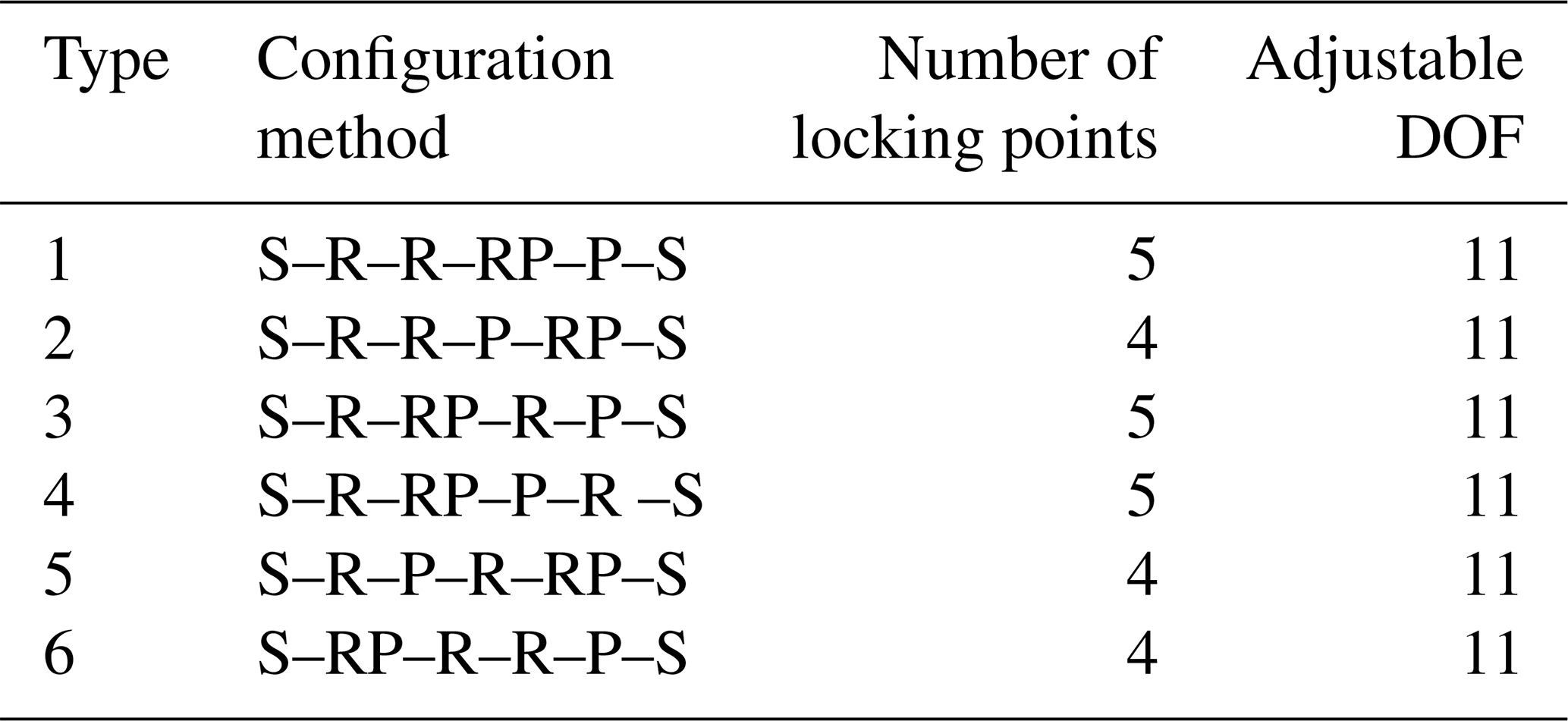
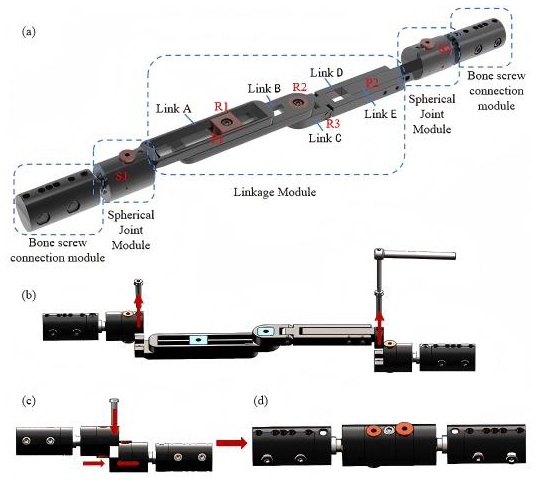
As shown in Table 2, under the condition of using spherical joint boundary constraints at both ends, there are six candidate connection sequences composed of rotational joints, translational joints, and compound motion joints. The compound motion joint RP is placed at the proximal end of the mechanism, possessing the combined adjustment capability of “angle adjustment and length compensation”. The intermediate R–R motion joint enables the main body of the mechanism to achieve posture transformation during the configuration adjustment process. Thus, it meets the configuration reconstruction, angle conversion, and spatial movement requirements for long-bone fixation and cross-joint fixation. At the same time, it ensures the force transmission direction and force stability of the middle part. By placing the independent translational joint P at the other end, the device can still perform secondary compensation for the terminal fixation span after completing the compound adjustment and posture expansion to improve the flexibility of the configuration. Therefore, compared to the other five configuration methods, the configuration S–RP–R–R–P–S is more conducive to establishing the adjustment assembly sequence and stable load path transmission and can meet the rapid fixation requirements for multi-dimensional, multi-attitude, and multi-scenario applications of temporary external fixation. Based on the comprehensive analysis of the configuration, the final external-fixation frame structure design is shown in Fig. 1a.
In the tibia and/or femur fixation mode, the intermediate five-link system is detached only by the screws on both sides, as shown in Fig. 1b. The two spherical-hinge structures on both sides are then joined and quickly secured with a single screw, as shown in Fig. 1c. The final configuration in the tibia and/or femur fixation mode is shown in Fig. 1d.
In the joint-spanning fixation mode, the mechanism is reconfigured into the configurations required for different joint-spanning fixations by pre-locking selected hinges, allowing it to closely conform to both sides of the diaphysis and provide high-strength fixation. By adjusting the length of the external fixator according to the limb length of different patients, the system is set to the appropriate configuration and length; after inserting the bone screws for fixation, the remaining hinges are locked to maintain stability at the fracture site.
This innovative design overcomes the drawback of traditional modular external fixators, which require disassembly and reassembly of numerous components. Only a few key locking units need to be tightened or loosened, and the two fixation modes can be rapidly switched using a single screw for simple attachment and detachment. By manually adjusting the configuration of the external fixator, it can meet the fixation requirements of fractures at different sites. The entire process is simple and convenient, significantly reducing the operational burden on rescue personnel. This design is of great value in rescue scenarios. It perfectly meets the dual requirements of speed and reliability in emergency rescue under special environmental conditions.
2.2 Workspace analysis
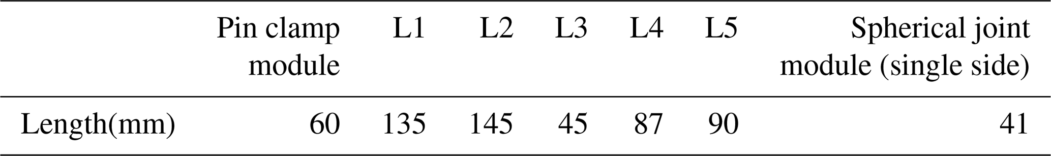
The link length parameters are defined according to clinically common dimensional requirements and human limb length parameters, as listed in Table 3. A kinematic analysis method based on the D–H parameter method is adopted. By establishing the kinematic model of the mechanism and analysing its workspace in each operating mode, theoretical support is provided for the feasibility and effectiveness of its clinical application (Meng et al., 2022).
Table 3Structural parameters of the links of the reconfigurable mechanism.
2.2.1 Femoral and/or tibial fixation mode
In the femur and/or tibia fixation mode, the main structure consists of a three-link assembly connected by two spherical joint modules, and the working space of the fixator is primarily adjusted via the spherical joints on both sides.
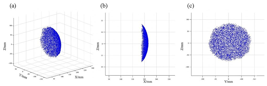
First, to ensure safety and adaptability during clinical use, the link parameters are defined as listed in Table 1. Second, a numerical method is employed to compute the workspace corresponding to all reachable positions of the links and rotations of the spherical joints in this mode, as illustrated in Fig. 2. The blue region in the figure denotes the workspace of the link endpoint. The results indicate that, after locking the spherical joints to reconfigure the mechanism into the femur and/or tibia fixation configuration, its workspace mainly serves to adjust the angle and length. The maximum length of the primary functional region for femur and/or tibia fracture fixation is 210 mm. The workspace of the external fixator is sufficient to meet the spatial requirements for external fixation of femoral and tibial fractures in clinical practice and allows better conformity to the contour of the limb.
2.2.2 Cross-joint fixation mode
In the joint-spanning fracture fixation mode, three types of joint-spanning limb fracture fixation are realized by configuration switching of the spatial reconfigurable seven-link mechanism. As it is necessary to simultaneously ensure stable fixation of the fracture ends and satisfy the spatial requirements of joint-spanning fixation, workspace analysis in this mode is particularly critical. To quantitatively analyse the workspace characteristics in this mode, the D–H parameter method is adopted to establish the kinematic equations of the mechanism (Niu et al., 2025).
By solving the forward kinematics (Antonov et al., 2025; Mishra et al., 2025; Vergara-Hernandez et al., 2025), the pose transformation matrix of the distal bone-pin connection module is determined as follows:
Where is the position vector of the origin of the end-effector frame expressed in the base coordinate system. The three column vectors of are the direction vectors of the three coordinate axes of the end-effector frame in the base frame, representing the end-effector orientation. On this basis, incorporating the range constraints of the joint variables, the workspace boundaries were systematically computed using numerical analysis methods, as shown in Fig. 3.
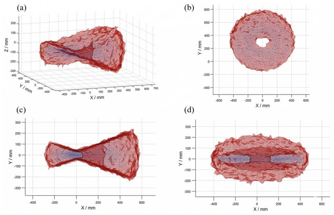
The workspace of the joint-spanning external fixator is calculated as shown in Fig. 3. Figure 3a represents the set of all points that the bone-pin module at the free end can reach via reconfiguration of the intermediate link structure from the fixed-end module. Figure 3b, c, and d show the projections of this workspace on three orthogonal planes. The results indicate that, in the simulated configurations for the knee, ankle, and elbow joints, the attainable workspace of the mechanism fully covers the required ranges for fracture fixation of each joint.
The multiple configuration transitions of the seven-link mechanism are primarily applied in joint-spanning fixation scenarios. Based on the design principles of kinematic chain locking and virtual hinges, the configurations for elbow-spanning, ankle-spanning, and knee-spanning fixation are pre-adjusted. At the corresponding joint-spanning positions, a controllable kinematic chain with a single degree of freedom is formed by releasing specific hinges. Functionally, this kinematic chain is equivalent to a lockable “virtual hinge”; by adjusting its spatial arrangement and axis orientation, it can be aligned with the physiological axis of the human joint, as shown in Fig. 4. This design enables the external fixator, in its locked state, to provide both axial and torsional stability.
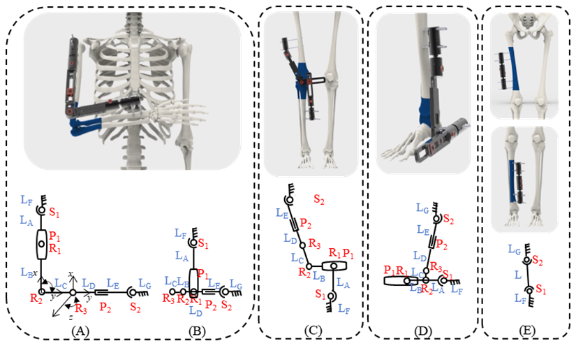
The key to achieving multi-modal reconfiguration lies in the configuration-switching mechanism. According to the operation specifications and screw placement requirements of orthopaedic external fixators (Bible and Mir, 2015; Chao and Hein, 1988; Fragomen and Rozbruch, 2007), four external-fixator configurations of the linkage system are predesigned in this study to correspond to three target joint-spanning fixation modes, as shown in Fig. 4. For each configuration mode, specific combinations of hinges are either pre-locked or kept with designated degrees of freedom. During actual use, reconfiguration of the mechanism does not require disassembly of any core links; the linkage structure is simply adjusted to the target configuration, after which the predefined key hinges are tightened.
In the elbow-spanning fixation mode, the upper limb is flexed to 90° and fixed in front of the chest according to fracture fixation requirements. Depending on the distance of the fracture site from the elbow joint, two postural configurations of the external fixator are constructed, as schematically illustrated in Fig. 4A and B. When the fracture site is relatively far from the elbow joint, the external fixator is rotated 90° about R2, and the remaining hinge angles and link lengths are adjusted to configuration (Fig. 4A). When the fracture site is closer to the elbow joint, the external fixator is rotated 90° about R1, and the remaining hinge angles and link lengths are adjusted, folding the links to a shorter overall length to achieve configuration (Fig. 4B). Both configurations can be used for elbow-spanning fixation.
According to the requirements for knee-spanning external fixation in long-bone fracture management, the screws are to be inserted on the lateral side of the thigh and the medial side of the lower leg. A schematic and structural diagram are shown in Fig. 4C. The entire external fixator must span the knee joint in space, with the screw fixation modules located on opposite sides of the limb. By adjusting the spatial position of the key hinge C, as well as the lengths and angular positions of the various links, an asymmetric spatial configuration is achieved, as illustrated in Fig. 4C, allowing the fixator to span the knee joint coaxially while remaining on different sides of the limb. For fractures located near the ankle joint that require ankle-spanning fixation, the corresponding spanning configuration is shown in Fig. 4D.
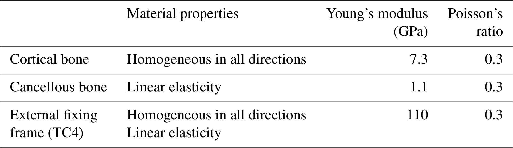
Since both the tibia and the femur are non-hinged long bones fixed in place, their structural topologies, constraint methods, and mechanical action mechanisms are the same. The differences mainly lie in the geometric scale and load parameters rather than the change in the configuration itself. Therefore, the finite-element analyses of these two configurations are classified into the same category. To verify the rationality of the configuration design of the seven-link reconfigurable external fixator, finite-element analysis was performed to conduct biomechanical simulations for the four configurations and to establish a static analysis environment. The cortical bone, the cancellous bone, and all components in the four configurations were simplified as continuous, homogeneous, isotropic, linear elastic materials, and the corresponding material parameters were defined for the simulations (Hadeed et al., 2019; Leonardo-Diaz et al., 2020; Russo et al., 2018).
An oblique fracture of 20° was set in the fracture model, with a 5 mm defect at the fracture end and a 5 mm gap between the two fracture fragments to simulate an unstable fracture (Raja Izaham et al., 2012). The distance between the external fixator and the bone was set to 30 mm. Since the morphology of the bone is approximately cylindrical, particularly in the diaphyseal region, a cylinder was used to approximate its geometric characteristics. The materials involved in the simulation and their properties are listed in Table 4.
The boundary conditions for axial loading were defined as follows: to prevent displacement during the analysis, the distal end of the fractured bone was fixed, and an axial load of 1500 N was applied to the proximal end to represent axial compressive loading (Abdul Wahab et al., 2020).
The boundary conditions for torsional loading were defined as follows: the distal bone end was fixed, and the proximal bone end was subjected to a torque (T = 15 N m).
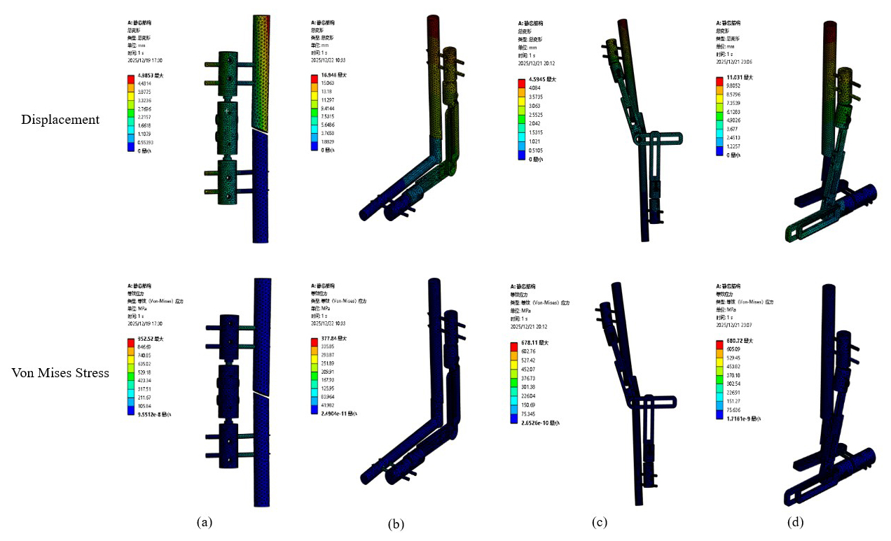
Figure 5Equivalent stress and total deformation of each mode. (a) Femoral/tibial fixation. (b) Elbow joint fixation. (c) Knee joint fixation. (d) Ankle joint fixation.
Using finite-element analysis software in combination with SolidWorks for the 3D model, the total deformation and overall stress distribution of the four configurations under axial load and torque were analysed, as shown in Fig. 5, and the corresponding numerical results are presented in Table 5.
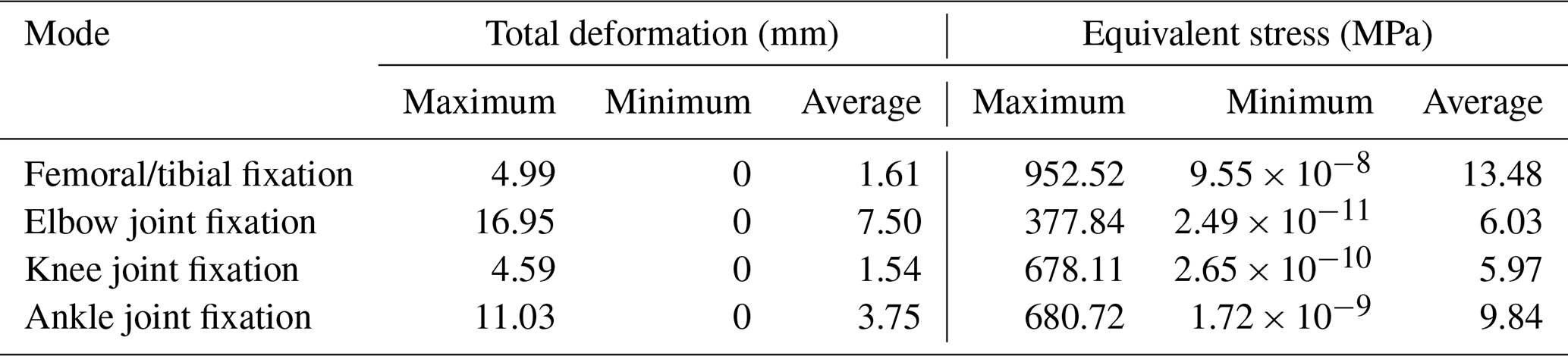
Table 5Equivalent stress and total deformation values of each mode.
It is well known that, for ductile materials, yielding occurs when the stress reaches the stress limit (Abd Aziz et al., 2020). The stress distribution and deformation of each fixation configuration under axial load and torque are shown in Fig. 5.
According to the specific values in Table 5, under an applied axial load of 1500 N and a torsional moment of 15 N m, the total deformation and equivalent stress of the external fixator were evaluated for different fixation configurations. For the femur/tibia configuration, the total deformation ranged from 0 to 4.99 mm, and the equivalent stress ranged from 9.55 × 10⁻⁸ to 952.52 MPa. For the elbow joint configuration, the total deformation ranged from 0 to 16.95 mm, with equivalent stress values ranging from 2.49 × 10⁻¹¹ to 377.84 MPa. For the knee joint configuration, the total deformation ranged from 0 to 4.59 mm, and the equivalent stress ranged from 2.65 × 10⁻¹⁰ to 678.11 MPa. For the ankle joint configuration, the total deformation ranged from 0 to 11.03 mm, with equivalent stress values ranging from 1.72 × 10⁻⁹ to 680.72 MPa. The highest stress in the external fixator in this study is concentrated at the interface between the bone pins and the bone. However, the maximum stress in each mode is lower than the allowable stress of the titanium alloy, indicating that the stability of the designed external fixator is acceptable.
Under the applied ultimate load and torque, the overall deformation remains within a range that allows the external fixator to be used for temporary fixation. In summary, based on finite-element simulations of the four modes under loading, although the biomechanical performance of the proposed external fixator is slightly inferior to that of a circular external fixator, it provides sufficient stability and structural rationality for temporary fixation.
5.1 Prototype processing and testing
Based on the above theoretical analysis, the final configuration dimensions were determined. A prototype of the external fixator was processed and fabricated using titanium alloy material to ensure its biocompatibility and mechanical properties met clinical requirements, as shown in Fig. 6a. The complete external-fixation system consists of one external fixator, four bone screws, and a universal wrench.
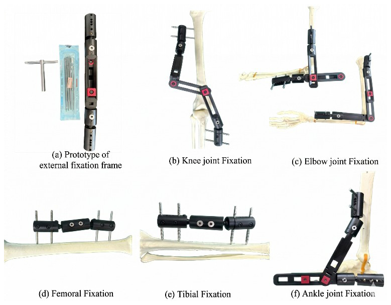
The prototype was applied to a high-fidelity skeletal model to systematically verify its effectiveness in fracture fixation at different anatomical locations. The experiments simulated mid-shaft fractures of the tibia and femur, as well as complex fracture fixation scenarios spanning the knee, ankle, and elbow joints, as shown in Fig. 6a–f.
The installation time required for all fixation configurations of the proposed system was compared with the assembly time of the corresponding single-function external fixator. The fixation procedures of the proposed external fixator were completed within 10 min, whereas the installation time for the Orthofix external fixator was less than 20 min.
The results demonstrated that the seven-link reconfigurable external-fixation system exhibited excellent clinical adaptability across all five fixation modes. For tibial and femoral fixation, the system provided stable, rigid fixation using a simplified single-joint configuration. In cross-joint fixation, by precisely adjusting the spatial configuration, the system maintained stable fixation of the fracture ends while effectively avoiding interference with periarticular soft tissues and bony prominences.
All fixation procedures were completed within the intended design time; configuration transitions were smooth, and the locking mechanisms functioned reliably. These experiments fully confirm that the external-fixation system can meet the fixation requirements of fractures involving the major long bones of the limbs and the surrounding joint regions, thereby achieving the design goal of “one device, multiple applications” and providing practical support for its use in clinical settings, particularly in emergency and rescue scenarios.
5.2 Mechanical testing of external fixators for cross-joint fixation
According to the overall mechanical performance test for external-fixation frames specified in the bone pin connector mechanical test methods of YY/T 1782–2021 “Mechanical testing methods for orthopaedic external-fixation frames”, a simulated fracture model was created, and the external fixator was mounted on a test rod and secured on the test bench to evaluate the global mechanical performance of the construct, as shown in Fig. 7a.
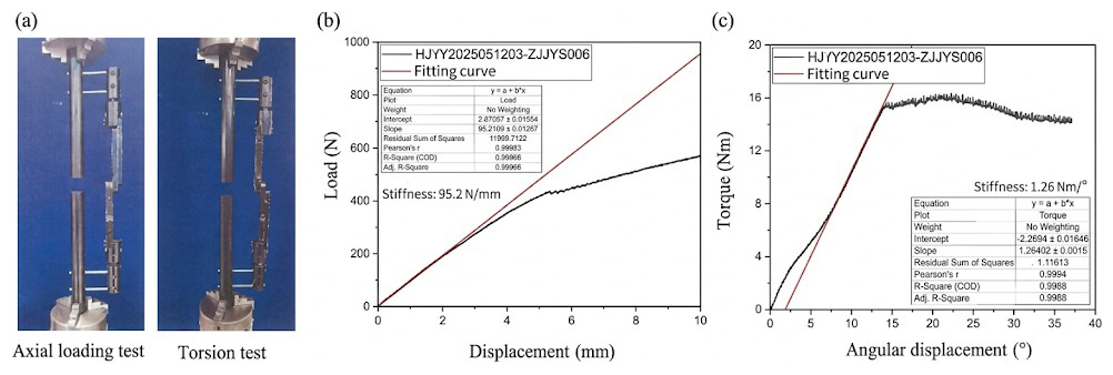
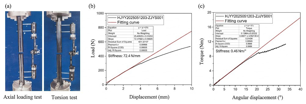
The external fixator was installed on a bone surrogate test rod, and axial and torsional loads were applied, respectively. The results are shown in Fig. 8b and c. Under axial loading, when the relative displacement at the fracture site exceeded 3 mm, the applied load was 274.2 N, corresponding to a stiffness of 95.2 N mm−1. In the torsion test, when the relative rotational angle at the fracture site exceeded 30°, the applied torque was 14.6562 N m.
These mechanical test results indicate that the external fixator provides mechanical performance sufficient to meet clinical fixation requirements.
In addition, the prototype of the newly developed external-fixation system was compared with a currently marketed and clinically used imported single-arm external-fixation system (Orthofix) of the same type. Mechanical tests were performed using the same methods, and the results are shown in Fig. 8. When the relative displacement at the fracture site exceeded 3 mm, the applied load for the Orthofix external fixator was 237.63 N, corresponding to a structural stiffness of 72.4 N mm−1. When the relative rotation angle at the fracture site exceeded 30°, the applied torque for the Orthofix external fixator was 10.4025 N m.
A comparison of the mechanical test results between the prototype and the Orthofix system indicates that, under both axial loading and torsional loading, the mechanical performance of the proposed external-fixation prototype is slightly superior to that of the imported Orthofix single-arm external-fixation system.
5.3 Animal experiment
To evaluate the fracture fixation performance of the proposed external fixator, an animal experiment using a Beagle dog lower-limb fracture model was designed and conducted. Percutaneous pin placement was employed for temporary fixation to assess the stabilization effect of the external fixator on a canine femoral fracture model. In addition, a distal traction-loading test was performed to evaluate and compare the anti-traction load capacity of the external fixator, while the relative displacement of the fracture ends was measured with the assistance of X-ray imaging.
Three adult male Beagle dogs (n = 3), weighing 10.3, 11.3, and 11.5 kg, were used in this study. All animal experiments were conducted in accordance with the National Institutes of Health (NIH) guidelines for the care and use of laboratory animals and were approved by the Ethics Committee for Experimental Animals of Naval Medical University (approval number). A control group was also established using a commercially available and clinically applied external fixator of the same type (Orthofix, n = 3).
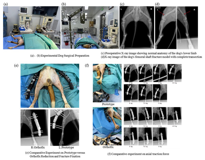
Due to the limited bone size of dogs, both the experimental group and the control group adopted a trans-knee external-fixation configuration. In the control group, the left or right limb was randomly selected for fracture fixation, as shown in Fig. 9. During the experiments, the relative displacement of the fracture ends was measured under X-ray guidance, and the anti-traction performance of the prototype and the control external fixator under axial-traction loading was compared.
After model creation, fracture reduction, and fixation, axial-traction loads of 1.5, 3, 4.5, 6, 7.5, and 9 kg were sequentially applied to the distal end of the fracture. A portable X-ray imaging system was used to capture fracture- end displacement under each loading condition, and the corresponding relative displacement values were measured and recorded. External-fixation failure was defined as a relative fracture end displacement exceeding 3 mm.
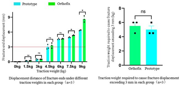
Figure 10Results of the axial-traction resistance experiment (ns – not statistically significant; ∗ – statistically significant (p < 0.05)).
Statistical analysis was performed using SPSS 24.0 (IBM, USA), and comparisons between the two groups were conducted using a paired t test. As shown in Fig. 10, when the axial-traction load was greater than or equal to 4.6 kg, the relative displacement at the fracture ends in both the prototype group and the control group gradually exceeded 3 mm. No statistically significant difference was observed between the two groups in terms of the traction load at which external-fixation failure occurred (p > 0.05), indicating that the prototype and the control external fixators exhibited comparable performance in resisting axial-traction loads and maintaining limited temporary fracture stability.
With further increases in traction load, the fracture end displacement in the prototype group tended to be smaller than that in the control group, suggesting that the prototype may provide enhanced stability under higher loading conditions and may help reduce the risk of pronounced fracture displacement under large axial loads.
This paper aims to solve the problems of the traditional external fixator, such as a single fixed dimension, limited application range, long fixation time, and heavy weight. A single-function external fixator is unable to meet the various needs of fracture fixation in scenarios involving a large number of injured patients. Therefore, this paper proposed a reconfigurable external fixator based on a seven-link mechanism. The configuration of the seven-link mechanism was comprehensively analysed, and a configuration design was proposed. A human–fixator coupled biomechanical model was established, and finite-element analysis was conducted to analyse the mechanical and stability performance of fractures in five typical reconfigurable configurations under an axial load of 1500 N and a torsional load of 15 N m. The finite-element simulation mechanical analysis shows that, under the action of 1500 N axial load and 15 N m torsional load, all configurations can control the relative displacement of the fracture ends within the clinical allowable range, and the overall structure remains stable. Subsequently, the performance, mechanics, and fixation time of this reconfigurable external fixator were compared with those of the single-function external fixator, and, finally, a comparative experiment was conducted based on dogs to verify. When the relative displacement of the fracture end reaches 3 mm, the load required by this reconfigurable external fixator is 274.2 N, and the corresponding structural stiffness is 95.2 N mm−1, both of which are higher than those of the Orthofix external fixator (237.63 N, 72.4 N mm−1); when the relative rotation angle of the fracture end reaches 30°, the required torque is 14.66 N m, which is also superior to the control device. The comparison results of fixation time further indicate that the overall fixation time of this system is less than 10 min, significantly shorter than that of the traditional single-function external fixator. The results of the dog cross-knee joint experiment verified the fixation stability of this external fixator under axial-traction load at the experimental level.
Overall, the seven-link reconfigurable external fixator proposed in this paper achieves rapid adaptation in multiple dimensions, multiple postures, and multiple fracture scenarios while ensuring structural stability and fixation reliability. By integrating multiple fixation modes into a unified topological framework, this design reduces the reliance on instrument replacement and module reconfiguration in emergency scenarios to a certain extent, providing a new structural path for improving the efficiency of temporary fracture fixation under complex conditions. At the same time, beyond its direct clinical application value, this study also demonstrates the feasibility of introducing reconfigurable mechanism concepts into orthopaedic external-fixation system design. Although reconfigurable and multi-mode mechanisms have been widely studied in robotics, deployable structures, and adaptive mechanical systems, their application in external-fixation devices remains relatively underexplored. Therefore, the proposed seven-link reconfigurable external fixator can also be regarded to be a new application case of reconfigurable mechanism theory in medical engineering, which helps extend the application scope of reconfigurable mechanism design in orthopaedic fixation systems.
No data sets were used in this article.
CF designed the seven-link reconfigurable mechanism, conducted theoretical research, and prepared the paper with contributions from all of the co-authors. ZJ developed the prototype machine. QM reviewed and edited the original paper. BZ designed the experiments and carried them out. BZ and XL managed the project and obtained the funding.
The contact author has declared that none of the authors has any competing interests.
Publisher's note: Copernicus Publications remains neutral with regard to jurisdictional claims made in the text, published maps, institutional affiliations, or any other geographical representation in this paper. The authors bear the ultimate responsibility for providing appropriate place names. Views expressed in the text are those of the authors and do not necessarily reflect the views of the publisher.
The authors gratefully acknowledge the financial support from the 2023 Oriental Elite Program Top Project (Comprehensive Platform grant no. SHSDFYCBJ-LXH), Shanghai Pujiang Program (grant no. o. 2023PJD114), and Research Funding of Shanghai Changzheng Hospital (grant no. 2024GCCRC-302).
This research has been supported by the 2023 Oriental Elite Program Top Project (Comprehensive Platform, grant no. SHSDFYCBJ-LXH), Shanghai Pujiang Program (grant no. 2023PJD114), and Research Funding of Shanghai Changzheng Hospital (grant no. 2024GCCRC-302). The APC was funded by 2023 Oriental Elite Program Top Project, Shanghai Pujiang Program and Research Funding of Shanghai Changzheng Hospital.
This paper was edited by Pengyuan Zhao and reviewed by two anonymous referees.
Abd Aziz, A. U., Abdul Wahab, A. H., Abdul Rahim, R. A., Abdul Kadir, M. R., and Ramlee, M. H.: A finite element study: Finding the best configuration between unilateral, hybrid, and ilizarov in terms of biomechanical point of view, Injury, 51, 2474–2478, https://doi.org/10.1016/j.injury.2020.08.001, 2020.
Abdul Wahab, A. H., Wui, N. B., Abdul Kadir, M. R., and Ramlee, M. H.: Biomechanical evaluation of three different configurations of external fixators for treating distal third tibia fracture: Finite element analysis in axial, bending and torsion load, Comput. Biol. Med., 127, 104062, https://doi.org/10.1016/j.compbiomed.2020.104062, 2020.
Almigdad, A., Mustafa, A., Alazaydeh, S., Alshawish, M., Bani Mustafa, M., and Alfukaha, H.: Bone Fracture Patterns and Distributions according to Trauma Energy, Advances in Orthopedics, 2022, 1–12, https://doi.org/10.1155/2022/8695916, 2022.
Antonov, A., Fomin, A., and Kiselev, S.: Inverse and forward kinematic analysis of a 6-DOF foldable mechanism with a circular rail (FoldRail mechanism), Mech. Mach. Theory, 206, 105904, https://doi.org/10.1016/j.mechmachtheory.2024.105904, 2025.
Belmont, P. J., McCriskin, B. J., Hsiao, M. S., Burks, R., Nelson, K. J., and Schoenfeld, A. J.: The Nature and Incidence of Musculoskeletal Combat Wounds in Iraq and Afghanistan (2005–2009), J. Orthop. Trauma, 27, e107–e113, https://doi.org/10.1097/BOT.0b013e3182703188, 2013.
Bible, J. E. and Mir, H. R.: External Fixation: Principles and Applications, J. Am. Acad. Orthop. Sur., 23, 683–690, https://doi.org/10.5435/JAAOS-D-14-00281, 2015.
Bliven, E. K., Greinwald, M., Hackl, S., and Augat, P.: External fixation of the lower extremities: Biomechanical perspective and recent innovations, Injury, 50, S10–S17, https://doi.org/10.1016/j.injury.2019.03.041, 2019.
Bull, D., Sykes, M., Saeidi, M., and Bull, A.: External fixators in austere environments under surge capacity conditions: A systematic review, Clin. Biomech., 124, 106500, https://doi.org/10.1016/j.clinbiomech.2025.106500, 2025.
Chao, E. Y. S. and Hein, T. J.: Mechanical Performance of the Standard Orthofix External Fixator, Orthopedics, 11, 1057–1069, https://doi.org/10.3928/0147-7447-19880701-09, 1988.
Evans, M., Kenwright, J., and Tanner, K. E.: Analysis of Single-Sided External Fracture Fixation, Engineering in Medicine, 8, 133–137, https://doi.org/10.1243/EMED_JOUR_1979_008_036_02, 1979.
Fernando, P. L. N., Abeygunawardane, A., Wijesinghe, P., Dharmaratne, P., and Silva, P.: An engineering review of external fixators, Med. Eng. Phys., 98, 91–103, https://doi.org/10.1016/j.medengphy.2021.11.002, 2021.
Fragomen, A. T. and Rozbruch, S. R.: The Mechanics of External Fixation, HSS Journal®: The Musculoskeletal Journal of Hospital for Special Surgery, 3, 13–29, https://doi.org/10.1007/s11420-006-9025-0, 2007.
Hadeed, M. M., Evans, C. L., Werner, B. C., Novicoff, W. M., and Weiss, D. B.: Does external fixator pin site distance from definitive implant affect infection rate in pilon fractures?, Injury, 50, 503–507, https://doi.org/10.1016/j.injury.2018.10.041, 2019.
Hoogervorst, P., Shearer, D. W., and Miclau, T.: The Burden of High-Energy Musculoskeletal Trauma in High-Income Countries, World J. Surg., 44, 1033–1038, https://doi.org/10.1007/s00268-018-4742-3, 2020.
Leonardo-Diaz, R., Alonso-Rasgado, T., Jimenez-Cruz, D., Bailey, C. G., and Talwalkar, S.: Performance evaluation of surgical techniques for treatment of scapholunate instability in a type II wrist, Numer. Methods Biomed. Eng., 36, e3278, https://doi.org/10.1002/cnm.3278, 2020.
Liu, J., Zhao, P., Chen, K., Zhang, X., and Zhang, X.: 1U-Sized Deployable Space Manipulator for Future On-Orbit Servicing, Assembly, and Manufacturing, Space Sci. Technol., 2022, 9894604, https://doi.org/10.34133/2022/9894604, 2022.
Medici, A., D'Onofrio, E., Mazzoleni, M. G., Tangredi, B., Tramontano, A., and De Simone, A. M.: Major trauma, definitive treatment of the lower limbs, Lo Scalpello, 37, 42–54, https://doi.org/10.36149/0390-5276-275, 2023.
Meng, Q., Fei, C., Jiao, Z., Xie, Q., Dai, Y., Fan, Y., Shen, Z., and Yu, H.: Design and kinematical performance analysis of the 7-DOF upper-limb exoskeleton toward improving human-robot interface in active and passive movement training, Technol. Health Care, 30, 1167–1182, https://doi.org/10.3233/THC-213573, 2022.
Mishra, A., Kumar, P., Ghosh, P., and Tiwari, N.: Forward kinematics and dynamics modeling of a 2PRU-1PRS parallel manipulator, Acta Mech., https://doi.org/10.1007/s00707-025-04581-6, 2025.
Niu, Q., Zhao, J., Liang, L., Xing, J., Li, H., and Wang, Z.: A general framework for the analytical inverse kinematics solution of industrial robots, Proc. Inst. Mech. Eng. Part C-J. Eng. Mech. Eng. Sci., 239, 4499–4511, https://doi.org/10.1177/09544062251318236, 2025.
Raja Izaham, R. M. A., Abdul Kadir, M. R., Abdul Rashid, A. H., Hossain, M. G., and Kamarul, T.: Finite element analysis of Puddu and Tomofix plate fixation for open wedge high tibial osteotomy, Injury, 43, 898–902, https://doi.org/10.1016/j.injury.2011.12.006, 2012.
Russo, A.-P., Caubere, A., Ghabi, A., Grosset, A., Mangin, P., Rigal, S., and Mathieu, L.: Sequential management of tibial fractures using a temporary unicortical external fixator, SICOT-J, 4, 39, https://doi.org/10.1051/sicotj/2018035, 2018.
Seligson, D.: Evolution of the Hoffmann Fixators, Injury-Int. J. Care Inj., 46, S3–S6, https://doi.org/10.1016/S0020-1383(15)30003-6, 2015.
Sever, M. Ş., Katı, Y. A., and Özkaya, U.: Destructive disasters, trauma, crush syndrome, and beyond, AOTT, 57, 306–314, https://doi.org/10.5152/j.aott.2023.23147, 2024.
Stern, C. A., Stockinger, Z. T., Todd, W. E., and Gurney, J. M.: An Analysis of Orthopedic Surgical Procedures Performed During U.S. Combat Operations from 2002 to 2016, Mil. Med., 184, 813–819, https://doi.org/10.1093/milmed/usz093, 2019.
Tresley, J., Schoenleber, S. J., Singer, A. D., and Clifford, P.: “Ilizarov” external fixation: what the radiologist needs to know, Skeletal Radiol., 44, 179–195, https://doi.org/10.1007/s00256-014-2001-8, 2015.
Vergara-Hernandez, R., Gonzalez-Islas, J.-C., Dominguez-Ramirez, O.-A., Rueda-Soriano, E., and Serrano-Chavez, R.: Dual Quaternion-Based Forward and Inverse Kinematics for Two-Dimensional Gait Analysis, J. Funct. Morphol. Kinesiol., 10, 298, https://doi.org/10.3390/jfmk10030298, 2025.
Wang, J., Tian, Y., Xi, F., Chablat, D., Ren, G., and Zhao, Y.: A Pill Bug-Inspired Two-Mode Mobile Robot Covered With Sliding Curvy Shells, IEEE Trans. Robot., 42, 1275–1289, https://doi.org/10.1109/TRO.2026.3661723, 2026.
Weil, Y. A. and Mosheiff, R.: High-Energy Injuries Caused by Penetrating Trauma, in: The Poly-Traumatized Patient with Fractures, edited by: Pape, H.-C., Sanders, R., and Borrelli, J., Springer Berlin Heidelberg, Berlin, Heidelberg, 281–293, https://doi.org/10.1007/978-3-642-17986-0_23, 2011.
Widanage, K. N. D., De Silva, M. J., Dulantha Lalitharatne, T., Bull, A. M. J., and Gopura, R. A. R. C.: Developments in circular external fixators: A review, Injury, 54, 111157, https://doi.org/10.1016/j.injury.2023.111157, 2023.
Wolfson, N., Lerner, A., and Roshal, L.: Orthopedics in Disasters: Orthopedic Injuries in Natural Disasters and Mass Casualty Events, Springer Berlin/Heidelberg, Berlin, Heidelberg, 1 pp., ISBN 978-3-662-48948-2 , 2016.
Yun, H. C., Murray, C. K., Nelson, K. J., and Bosse, M. J.: Infection After Orthopaedic Trauma: Prevention and Treatment, J. Orthop. Trauma, 30, S21–S26, https://doi.org/10.1097/BOT.0000000000000667, 2016.
- Abstract
- Introduction
- Configuration synthesis
- Human–fixator coupling and reconfigurable configuration modelling
- Biomechanical finite-element analysis
- Prototype production and experimental verification
- Conclusions
- Data availability
- Author contributions
- Competing interests
- Disclaimer
- Acknowledgements
- Financial support
- Review statement
- References