the Creative Commons Attribution 4.0 License.
the Creative Commons Attribution 4.0 License.
 | 09 Mar 2026
Design and dual-loop control of a wearable electric force-feedback device for virtual training
Zhexue Ge
Liming Zhang
Haiyang Sun
Suiyu Chen
Xu Luo
Yongmin Yang
Virtual training is increasingly used in equipment maintenance. However, conventional haptic devices often suffer from limited force accuracy and poor wearing comfort in limb-interaction scenarios. This study presents an electro-actuated wearable force-feedback device for forearm interaction based on a compact direct current (DC) servo motor and cam mechanism. A simplified mathematical model is established to relate cam rotation angle to output feedback force, enabling quantitative force control. To handle dynamic load variations, a phase-shift–torque dual closed-loop control strategy is implemented by coordinating position and current regulation. The system is validated through physical experiments and virtual maintenance training, demonstrating rapid collision response and stable performance. Experimental results show a maximum feedback force of 32.37 N and consistently low errors. Overall relative errors were maintained within approximately 4.6 % and there was minimal variance across repeated trials. These results indicate that the proposed device can reliably enhance realism and immersion in virtual training applications.
- Article
(2763 KB) - Full-text XML
- BibTeX
- EndNote


Traditional physical training for various tasks, such as equipment operation and industrial maintenance, faces several challenges, including high costs, significant safety risks, and spatial constraints. However, by the construction of digital prototypes and three-dimensional interactive environments, virtual training techniques can serve as effective substitutes for physical operations, thereby reducing costs and mitigating risks (Xu et al., 2024; Lee et al., 2016). With advancements in virtual reality (VR) and augmented reality (AR), the immersion and realism of human–computer interactions have become critical metrics by which virtual training systems are evaluated (Tao et al., 2022; Cherif et al., 2024). Haptic feedback, which is a crucial component of human–computer interactions, simulates physical sensations (such as hardness, texture, and reaction forces) using mechanical, electrical, or material-based approaches (Han, 2024; Katranitsiotis et al., 2024; Webb et al., 2022). Thus, it enhances the realism of virtual training (Tan et al., 2025).
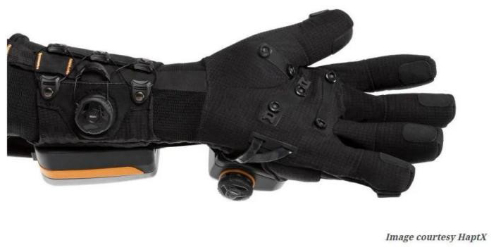
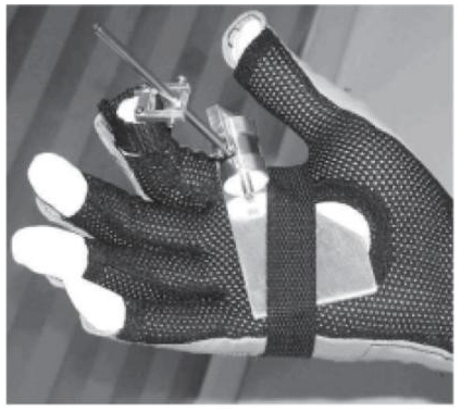
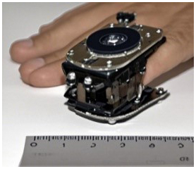
Existing haptic devices include the HaptX Gloves, which were launched by HaptX in 2009, as shown in Fig. 1. These gloves confirmed the efficacy of using electromagnetic actuation for high-precision industrial training (Blake and Gurocak, 2009). In 2010, Song et al. (2023) proposed a magnetorheological-fluid-based haptic actuator to address the safety and limited force-range issues of haptic data gloves, as shown in Fig. 2 (Dai et al., 2010). Recent studies show that MR materials and fluids remain a strong route for compact, tunable-force/variable-impedance haptic interfaces. MR-based tactile/force devices have demonstrated controllable stiffness/force in surgical or teleoperation settings (Song et al., 2023), and reviews of MR brakes/clutches report ongoing miniaturization and improved controllability toward wearable or hand-held systems (Wu et al., 2025). The Haptigami device from École Polytechnique Fédérale de Lausanne, which was inspired by origami, employs a dual piezoelectric cantilever structure to deliver multidimensional force and vibration feedback using only two flat piezoelectric motors, as shown in Fig. 3 (Giraud et al., 2022).
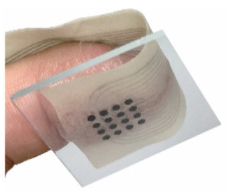
In 2023, Tan et al. (2023) introduced PixeLite, which is a wearable haptic array that generates lateral-force and vibration feedback through voltage, frequency, and phase adjustments, as shown in Fig. 4 (Tan et al., 2023). Also in 2023, Zhang et al. (2023) developed SmartSpring, which is a low-cost wearable haptic display that is integrated with HTC VIVE for continuous force feedback in VR applications, as shown in Fig. 5 (Zhang et al., 2023; Boutin et al., 2024).
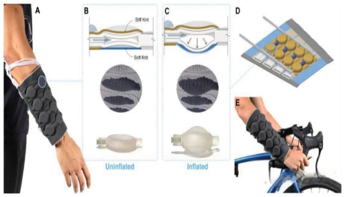
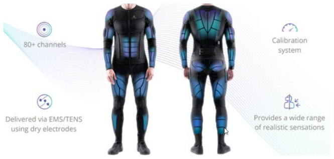
The Haptiknit haptic sleeve developed by Stanford University enhances tactile localization precision using a 40 N pneumatic actuator array, as shown in Fig. 6 (Schneider et al., 2015). In 2019, Pang (2019) designed a magnetorheological damper-based haptic data glove; however, the five dampers on the dorsum of the glove reduce its long-term wearability (Pang, 2019). The Teslasuit Pro from Tesla Interactive, UK, integrates IMU motion tracking with the Unity engine to convert virtual environmental force data into real-time electro-tactile signals, as shown in Fig. 7 (Mubarrat et al., 2024). Figure 7 presents the Teslasuit Pro, which integrates IMU tracking with electro-tactile feedback for real-time force simulation in VR environments.
Despite progress, all the existing haptic devices possess limitations: piezoelectric devices are cumbersome to wear; pneumatic systems have limitations such as dispersed control and poor real-time performance; electromagnetic and magnetorheological systems offer high precision but are costly and uncomfortable; and electro-tactile systems require close contact with the skin, which complicates their operation (Park, 2025). Beyond actuation, rigorous evaluation of feedback force is essential. Prior studies typically (i) directly measure with force sensors/load cells and calibration, (ii) estimate via current/torque–force models with experimental correction, and (iii) report dynamic metrics such as force accuracy, noise, and response behavior (Liu et al., 2022). Yet for wearable systems under dynamic contact/collision, simultaneously achieving (a) compact wearability, (b) an explicit and verifiable control-to-force mapping, and (c) fast, stable closed-loop behavior remains difficult. It would therefore be advantageous to leverage the response rapidity, high control precision, and strong integrability of electro-actuated haptic feedback (Tang et al., 2024; Tao et al., 2023). During this study, an integrated haptic structure was designed, a feedback-force model was derived, and a phase-shift–torque dual-loop control system for precise angle and torque control was developed. Accordingly, we establish a reproducible, measurable force-rendering pipeline – from model to control to validation – while preserving wearability and rapid collision response for virtual training. The accuracy and effectiveness of the device were validated using both physical and virtual training experiments.
2.1 System architecture design
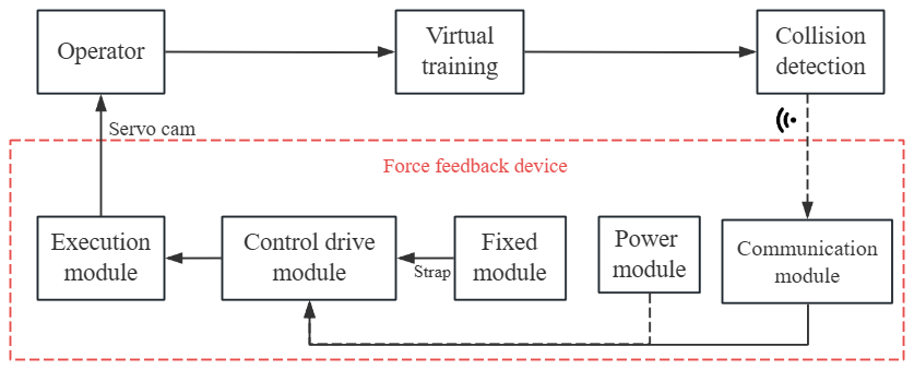
During this study, a wearable haptic feedback control system was developed based on a DC servo-motor model. The overall system architecture, including the functional relationships among modules, is illustrated in Fig. 8. The system addresses key challenges in feedback-force computation and precise servo control, and is designed for an arm-mounted haptic device (Dragone et al., 2023). It consists of fixation, wireless-communication, control-drive, actuation, and power modules, whose interactions follow the signal and control flow shown in Fig. 8. The fixation module ensures stable positioning of the motor and haptic interface, while the power module continuously supplies electrical power to the control-drive module to maintain reliable operation. In the virtual-training scenario for which this system is intended, limb interactions occurring within the virtual environment are first captured and converted into electrical signals by the wireless-communication module. These signals are then forwarded to the control-drive module, which processes them according to the DC servo-motor model and generates the corresponding control commands. The actuation module receives these commands and drives the motor to actuate the cam with precise phase shifts, thereby producing the required haptic force output. This closed-loop haptic feedback design not only reduces injury risk but also enhances the realism and immersion of the training experience.
2.2 Haptic device design and force calculations
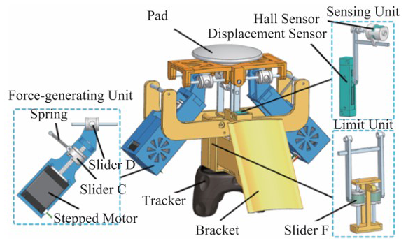
2.2.1 Structural design of the force-feedback device
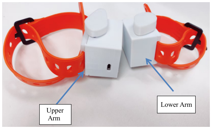
A modular design configuration was adopted to improve the performance, compactness, and mechanical integration of the wearable haptic device. The fixation module, which is responsible for both force transmission and wearer comfort, employs a split wearable structure that converts the physical haptic output while maintaining ergonomic compatibility. In addition to accommodating miniaturization requirements and the dimensional constraints of the DC servo motor, the design introduces several structural optimizations to enhance mounting stability and force-transmission efficiency.
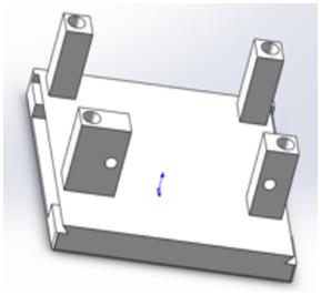
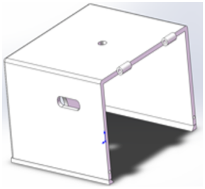
The base structure, shown in Fig. 9, incorporates a transverse rectangular through-slot that enables a screw-free interlocking connection among the strap, outer shell, and base. This configuration not only increases assembly reliability and reduces hardware bulk but also provides improved lateral stability during force transmission. Furthermore, the outer shell and the strap-based fixation mechanism housed within the through-slot – illustrated in Fig. 10 – are designed to distribute the transmitted force more evenly across the user's arm while minimizing unintended reaction forces. The combination of the refined base geometry and the integrated shell-and-strap mechanism enhances structural rigidity, ensures stable fixation, and supports efficient delivery of the haptic output.
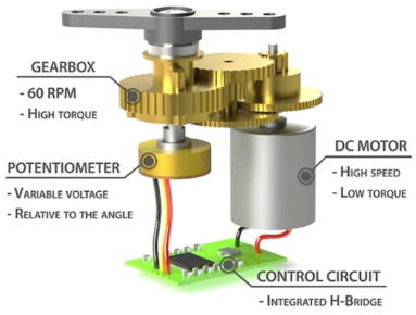
The wireless-communication module uses Wi-Fi to achieve efficient stable data transmission, thereby ensuring real-time delivery of collision data to the control-drive module. Because traditional motors are large, the SG90 micro servo motor, which integrates a DC motor and a gear set, was selected for its compactness and high torque, which makes it ideal for wearable applications (Fig. 11).
The actuation module, which comprises the motor and cam mechanism, was designed as shown in Fig. 12. This design enables haptic feedback control throughout a 120° range below the arm. Details on the force calculations are provided in the following section. The power module uses a lithium battery that is encapsulated within an aluminum–plastic composite film to achieve safety and a lightweight design. In addition, the edges and corners of the shell are rounded to enhance comfort and safety.
2.2.2 Feedback-force calculations
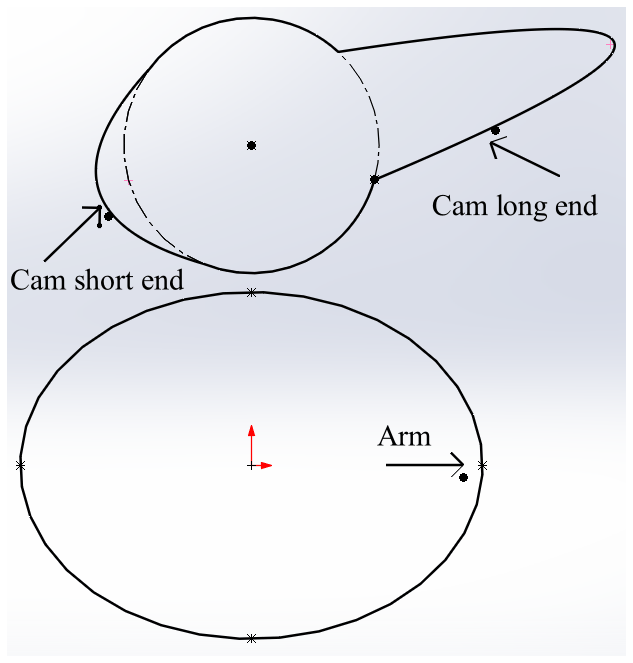
During the feedback-force calculation process, the geometric shape of the arm was simplified from its anatomical form to a dimensionless elliptical model described by the equation , in which the semi-major axis, a, was set to 20; and the semi-minor axis, b, was set to 15. These parameters represent normalized geometric dimensions used solely for computational modeling rather than physical measurements. The cam structure was formed by the intersection of a central circle and two parabolas, and the central circle used the standard circle equation. Due to their different modes of action, the two ends of the cam were divided into long-end and short-end structures. This study focused solely on a force-feedback analysis of the short end. This analysis employed the parabolic equation in the Cartesian coordinate system, as shown in Eq. (1), in which p was set to 3.3 and q was set to 13.8, respectively, and similarly represent dimensionless geometric quantities used for modeling rather than physical dimensions.
The cam model, which possesses both short and long ends, is depicted in Fig. 13. The short end, which acts below the wearable position of the arm, generates a feedback force by means of compression and friction. The long end, which acts on the lateral side of the arm, applies a force directly.
-
Force-feedback analysis at the short end of the cam
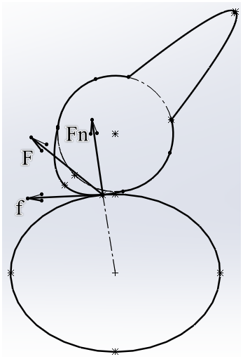
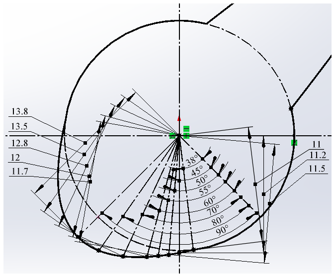
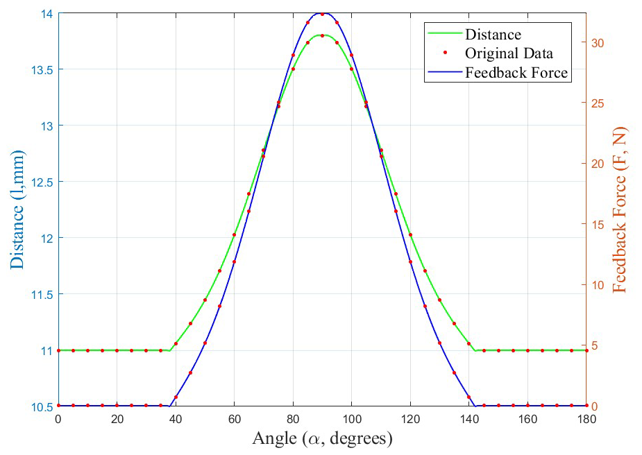
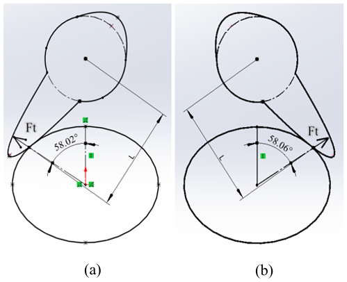
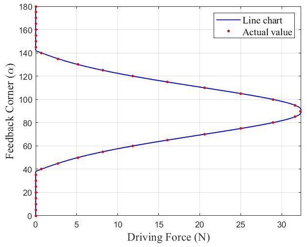
During short-end actuation, the cam initially remains out of contact with the arm. As the cam rotates, the short end approaches the arm through the parabolic segment and circular arc, making first contact at a rotation angle of 38°. The incremental rotation beyond this point is approximated as the compression of the short end into the arm, as illustrated in Fig. 14. Due to the geometric centers of the parabola and circle not being coincident, the direct polar-coordinate calculation of the relationship between the rotation angle, α, and the cam profile position leads to denominator singularities. Therefore, a numerical geometric method was adopted to derive a reliable mapping between α and the corresponding cam profile radius. In this method, lθ denotes the distance from the cam center to the contacting profile at any rotation angle α, while l0 represents the same distance at the initial contact angle of 38°, where l0 is measured as 11 mm. By comparing lθ to l0 over the rotation range, the evolution of cam–arm interaction can be determined. These measured and computed values were used to fit the functional relationship between lθ and α, as shown in Figs. 15 and 16.The cam acts on the arm, and the interaction at the short end is modeled by the normal contact force and the associated friction. Specifically, the normal contact force is expressed as
where l0 represents the radius of the cam base circle (here, l0=11 mm), lθ is the cam–arm distance at rotation angle θ, and k denotes the effective stiffness of the forearm soft tissue. To make clear why the material parameters are introduced, k is defined by a linearized tissue stiffness model as
where E is the Young's modulus of the forearm tissue, A is the effective force-bearing area, and L is the effective thickness of the deforming tissue layer. During the biomechanical modeling, we set E=0.12 MPa. According to optical coherence tomography measurements, L was determined to be 1.1 mm and A was determined to be 100 mm2. Substituting these values into Eq. (3) yields k=11.2 N mm−1. The feedback force is then modeled as
where μ denotes the friction coefficient between the cam and the skin surface (here μ=0.25). Substituting k, l0, and μ into Eq. (4) yields the relationship between the cam rotation angle and the feedback force under the action of the short end, as shown in Fig. 16.
-
Force-feedback analysis at the long end of the cam
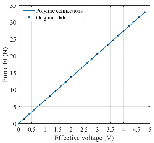
During long-end actuation, the force-feedback device maintains a fixed connection with the arm. Using the expressions for the motor torque and the torque, along with that of the servo-motor current, the feedback force of the cam on the arm was derived as follows:where U represents the effective voltage input to the servo motor, R=20 Ω is the operating internal resistance of the servo motor, kt=0.39 N m A−1 denotes the torque constant of the servo motor, N=20 is the gear ratio of the SG90 servo motor, η=0.8 represents the transmission efficiency, and L=0.028 m is the distance between the cam profile and the cam center. A schematic diagram that shows the long end acting on both sides of the arm is shown in Fig. 17. Figure 17 shows that adjustments to the cam angle enable haptic feedback control within a 120° range below the device. Pulse-width modulation (PWM) is used to adjust the effective voltage of the motor, thereby altering the feedback force. Substituting the parameter values into Eq. (5) yielded a relationship between the voltage and the feedback force, as shown in Fig. 18.
2.3 Closed-loop control-system design
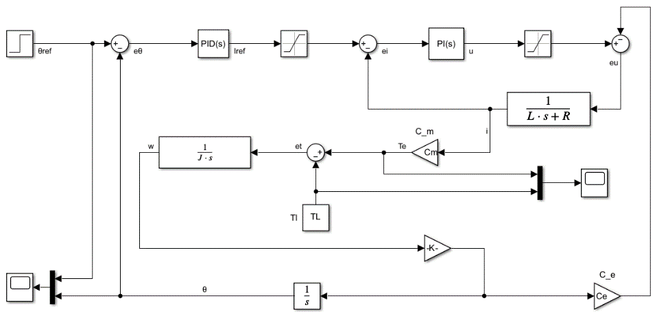
The adoption of the dual closed-loop architecture was primarily driven by the unique operating constraints of the wearable haptic system. First, the SG90 micro servo motor exhibits limited torque capacity and pronounced sensitivity to load variations when operating near its rated conditions. In force-feedback applications, the cam–arm interaction generates rapidly changing resistive torques, which cannot be reliably compensated by a position-only control loop. Second, the compact mechanical layout and the physical compliance of the arm introduce additional disturbances that require active current regulation to maintain stable actuation. Therefore, incorporating a current-regulated outer loop ensures that the motor can provide consistent output torque despite these disturbances, while the position inner loop preserves fast tracking performance. This tailored configuration enables the actuator to meet the force-feedback accuracy and stability requirements of the wearable system within the constraints imposed by size, power, and dynamic loading (Liu, 2016; Xie, 2023). The dual closed-loop control architecture shown in Fig. 19 provides the theoretical basis for controller parameter tuning. In this study, the electromechanical dynamics of the DC servo drive system were derived and linearized around a representative operating point. The architecture consists of a high-bandwidth current inner loop and a position outer loop: the inner loop rapidly regulates the electromagnetic torque, while the outer loop shapes the overall motion response of the system. This division of functionality enables the system to achieve both effective torque-disturbance rejection and high-precision position control performance.
-
Motor armature (electrical) dynamics:
where the parameters are , R=10 Ω, and Ce=1.2 V (rad s−1)−1. Here, i(t) is armature current, v(t) the applied voltage, and w(t) the motor angular velocity.
-
Output rotational dynamics (reflected to output side):
where Cm=0.2 N cm A−1, K=0.05 is the transmission ratio, and denotes the equivalent inertia at the output (including motor inertia reflected through the gearbox and any load inertia). The nominal load torque used in simulations is N cm.
-
Voltage-to-angle transfer function (linearized form): Linearization about a representative operating point yields the following transfer function from applied voltage v to output angle θ (Laplace domain):
After substituting the motor inertia, the motor-side inertia reflected to the output is given by kg m2. Owing to and R=10 Ω, the electrical pole is approximately s−1, indicating that the current dynamics are much faster than the mechanical dynamics. This supports the rationale for designing a high-bandwidth current inner loop, and the complete nonlinear Simulink model was used for time-domain simulation and validation.
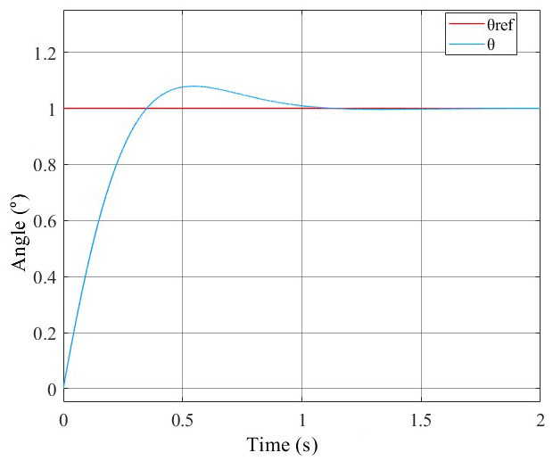
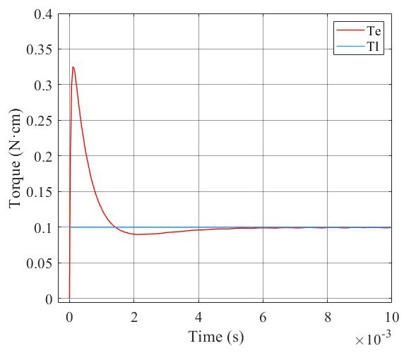
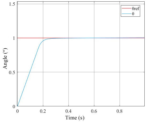
A step signal with an amplitude of 1 was input to the system. The PID controller parameters were determined following a structured engineering workflow. First, a low-order plant model of the actuator–load subsystem was obtained from measured step responses and used as an empirical basis for initial tuning. Conventional tuning heuristics were then applied to produce baseline gains, which were refined by time-domain simulation under representative loading scenarios to meet the specified transient objectives. Final parameter selection was performed through targeted experimental fine-tuning on the physical platform to ensure that the position response satisfied both transient and steady-state requirements. The final PID gains were selected as KP=9.7, Ki=38.7, and Kd=0.05. The system response results are presented in Figs. 20 and 21. The position response met expectations (settling within 2 s, overshoot < 6.3 %, steady-state error ≈ 0.012), but the torque response exhibited insufficient suppression, primarily because motor current peaks were not adequately limited.
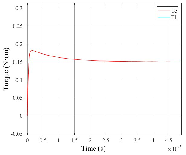
To address this issue, a current-loop PI controller was introduced. Its parameters were determined via a two-stage tuning procedure: an initial coarse tuning using a model-based self-tuning/auto-tuning algorithm to obtain conservative starting gains, followed by experimental fine-tuning to reduce current overshoot and optimize torque tracking. The resulting current-loop proportional and integral gains were chosen as KP=2.6 and Ki=0.8. The control results are presented in Figs. 22 and 23. With this parameter set, the motor position response stabilized within 0.5 s with negligible overshoot and a steady-state error of 0.01; the torque response settled in an extremely short time, demonstrating markedly improved dynamic performance.
3.1 Experimental validation of the force-feedback device
This section presents an experimental analysis of the relationships between the driving force of the feedback device, the servo-motor feedback angle, and actual feedback force (Qi and Chen, 2019). The experimental apparatus is shown in Fig. 24. It primarily consists of a spring force gauge and a feedback device. The top end of the spring force gauge is fixed, while the bottom end is connected to the cam of the feedback device.
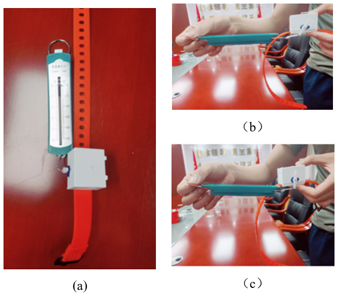
Figure 24Servo-motor feedback-force test. (a) Experimental setup. (b) Rotation angle, θ, of 60°. (c) Rotation angle, θ, of 90°.
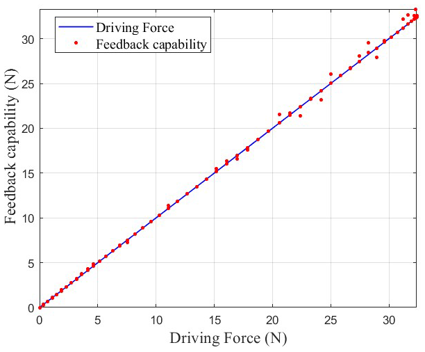
In the experiment, the effective voltage of the servo motor was adjusted by means of PWM signal control so that the cam generated various driving forces. The feedback angle and the actual feedback force that were measured by the spring force gauge under various driving forces are shown in Figs. 25 and 26, respectively. The experimental results indicate that the maximum driving force of the feedback device was approximately 32.37 N and that this maximum value corresponded to a maximum blade rotation angle of 90.7°. At this point, the maximum stroke of the penetration depth was achieved. The maximum relative errors of the theoretical feedback angle and driving force with respect to the measured values were 3.6 % and 4.8 %, respectively. The experiment also revealed that the magnitude of the driving force was closely related to the length of the lever arm of the servo motor. This result indicates that optimizing the lever-arm length can cause the system to adapt to different application scenarios and can improve the system performance.
3.2 Experimental verification of the virtual training application
In this study, the Jack and Unity software was used to build a virtual environment in which the operators wore VD Suit full inertial motion-capture devices while they performed virtual engine maintenance. When the maintenance actions of the operator caused the operator to collide with the engine in the virtual environment, the collision area was highlighted and the system quickly calculated the feedback force and feedback angle shift at the collision point. Wireless communication was then used to send the control signal to the force-feedback device that was worn on the forearm, causing it to produce a corresponding physical response.

Figure 27Force feedback in virtual training scenarios. (a) Inner-side effect. (b) Outer-side effect. (c) Front-side effect.
In experiments, operators performed engine maintenance tasks in the virtual environment. When arm-component collisions were detected, the system calculated a virtual feedback force according to the collision intensity and adjusted the feedback angle for precise device control. The testing process and visualizations of the collision positions (the front, inner, and outer sides) are shown in Fig. 27. The device responded rapidly to virtual collisions. Feedback forces of 11.57 and 11.86 N were obtained for inner and outer collisions, respectively, which corresponded to angles of 59.4 and 60.1°, respectively. A feedback force of 32.37 N was obtained for a front collision at 90.7°. The results of the virtual experiments aligned closely with those of the physical experiments. Repeated tests (five times per collision condition) yielded a mean error (± standard deviation) of 4.6 % ± 1.2 %, with low variance and all individual measurements below a 5.8 % error threshold. These quantitative findings provide a foundation for broader interpretation in the following Discussion section. These results confirmed the control accuracy and effectiveness of the device, which provides robust physical-interaction support for virtual maintenance training.
4.1 Synthesis of findings
The proposed wearable haptic device successfully demonstrates precise and reproducible force feedback in virtual maintenance scenarios through a compact DC servo motor and cam mechanism. Repeated measurements (five times per condition) yielded consistently low errors: mean relative errors (± standard deviation) of 3.6 % ± 0.8 % (feedback angle) and 4.8 % ± 1.1 % (driving force) in physical validation, and 4.6 % ± 1.2 % in virtual collision tests, with all trials remaining below an approximately 6 % error threshold and minimal variance. These results validate the derived simplified mathematical model and phase-shift–torque dual-loop control strategy, enabling rapid reliable collision response while preserving wearability and user comfort.
4.2 Comparison with existing systems and practical implications
Compared to existing piezoelectric, pneumatic, electromagnetic, or electro-tactile haptic devices, the proposed modular electro-actuated design offers superior real-time performance, reduced bulkiness, and lower reaction forces at a comparable or lower cost. The maximum feedback force of 32.37 N, combined with a 120° operational range below the arm, effectively addresses key limitations in prior wearable systems for limb-specific interactions. In practical terms, the device's low maximum force and rapid response significantly enhance safety in virtual maintenance training by minimizing injury risk during simulated collisions. The cost-effective design achieves high precision (errors consistently < 6 %) without expensive actuators, providing an attractive precision-to-cost tradeoff suitable for scalable industrial training applications where both immersion and operator safety are critical.
4.3 Limitations
Several important limitations should be acknowledged. The current implementation is restricted to forearm interactions, limiting applicability to other limbs or full-body scenarios. The feedback-force model assumes constant skin and tissue elasticity, which may not fully capture real-world biomechanical variations. Validation was conducted in a controlled proof-of-concept setting with limited trial repetitions (n = 5 per condition) and without multi-participant testing, precluding formal inferential statistical analysis (e.g., t tests or ANOVA). Although descriptive statistics confirm consistency, the absence of large-scale user studies also means that subjective presence evaluation and contemporary multimodal/physiological immersion metrics (e.g., updated presence questionnaires, physiological measures, or multisensory integration assessments common in recent 2025 studies) were not included. Finally, inter-subject variability in anthropometric parameters and skin properties remains unquantified. Preliminary parameter sensitivity analysis indicates moderate dependence on lever-arm length and assumed tissue stiffness (±20 % variation may increase errors to ∼ 8 %), highlighting the need for more robust modeling of individual differences.
4.4 Future work
All experiments in this study followed institutional ethical guidelines and the low-force design ensured minimal risk. Future extensions should continue to prioritize participant safety and formal ethical review, particularly as trial scale increases. Promising directions include the integration of thermal feedback for multisensory immersion; machine learning algorithms for real-time adaptation to individual biomechanics; and large-scale multi-participant trials to enable formal statistical analysis, baseline comparisons against commercial devices, and systematic evaluation of user variability. The incorporation of contemporary subjective and physiological presence metrics would further quantify immersion benefits and strengthen the validation of training efficacy.
In this study, a wearable haptic feedback device and its corresponding control strategy were developed for virtual maintenance training. The proposed device addresses several limitations commonly found in existing haptic systems, including insufficient force-feedback accuracy, inadequate wearing comfort, and poor adaptability to complex operational environments. To overcome these shortcomings, the device architecture was organized into clearly defined functional components, enabling the integration of a high-precision servo-motor-driven force-transmission mechanism while maintaining structural clarity and system extensibility. The main contributions of this study are summarized as follows:
-
Device design. A compact wearable force-feedback device based on a DC servo motor and cam mechanism was designed. A simplified mathematical model was derived to predict feedback force from cam rotation angle and control voltage. Experimental validation confirmed a maximum output force of 32.37 N at a rotation angle of 90.7°, with reproducible performance across repeated trials.
-
Control system. A Simulink-based control model was constructed, implementing a phase-shift–torque dual closed-loop scheme with hierarchical PID control. This approach enabled the precise regulation of angular phase shift and feedback force, achieving mean relative errors (± standard deviation) of 3.6 % ± 0.8 % (feedback angle) and 4.8 % ± 1.1 % (driving force) across five repeated measurements under identical conditions.
-
Virtual training integration. The device was deeply integrated with an inertial motion-capture system (VD Suit) and virtual environment (Jack and Unity) to form a complete interactive training platform. Virtual collision experiments across multiple maintenance tasks and forearm positions yielded feedback forces ranging from 11.57 to 32.37 N, with overall mean errors (± standard deviation) of 4.6 % ± 1.2 % (all individual trials below a 5.8 % threshold), confirming rapid, accurate, and reliable force rendering that significantly enhances realism, immersion, and safety in virtual maintenance training.
These quantitative results, combined with the device's cost-effective design and low reaction forces, demonstrate its practical potential for scalable industrial applications. Future extensions toward multisensory integration and large-scale validation will further strengthen its impact.
All data are given in the paper. No further datasets were used.
All authors contributed to the conception and design of the study. The device development, control design, experimental investigation, and data analysis were carried out by ZG, LZ, HS, and XL. The virtual training implementation and results interpretation were performed by SC and YY. The paper was written and revised with contributions from all authors. All authors read and approved the final article.
The contact author has declared that none of the authors has any competing interests.
Publisher's note: Copernicus Publications remains neutral with regard to jurisdictional claims made in the text, published maps, institutional affiliations, or any other geographical representation in this paper. The authors bear the ultimate responsibility for providing appropriate place names. Views expressed in the text are those of the authors and do not necessarily reflect the views of the publisher.
This work was supported by the National Natural Science Foundation of China (NSFC, grant no. 52371340) and the National Key Laboratory Fund (grant no. 6142003202406). We thank LetPub (http://www.letpub.com.cn, last access: 22 September 2025) for linguistic assistance during the preparation of this article.
This research has been supported by the Foundation for Innovative Research Groups of the National Natural Science Foundation of China (grant no. 52371340) and the National Key Laboratory Foundation of China (grant no. 6142003202406).
This paper was edited by Jeong Hoon Ko and reviewed by Nicolò Gori and one anonymous referee.
Blake, J. and Gurocak, H. B.: Haptic Glove with MR Brakes for Virtual Reality, IEEE/ASME Transactions on Mechatronics, 14, 606–615, https://doi.org/10.1109/TMECH.2008.2010934, 2009.
Boutin, J., Kamoonpuri, J., Faieghi, R., Chung, J., de Ribaupierre, S., and Eagleson, R.: The Use of Vibrotactile Haptic Feedback for a Neurosurgical Virtual Reality Training System, Proceedings of the 11th International Conference on Control, Dynamic Systems, and Robotics (CDSR 2024), https://doi.org/10.11159/cdsr24.128, 2024.
Cherif, I., Chellali, A., Babahenini, M. C., Simon, C., and Otmane, S.: The Role of Haptic Feedback in Enhancing Basic Technical Skills Acquisition and Transfer in an Immersive Simulator: A User Study, 2024 IEEE Conference on Virtual Reality and 3D User Interfaces Abstracts and Workshops (VRW), 691–692, https://doi.org/10.1109/VRW62533.2024.00142, 2024.
Dai, J., Wang, A., Song, A., and Zhang, H.: Passive force feedback actuator for force feedback data gloves, Journal of Southeast University (Natural Science Edition), 40, 123–127, https://doi.org/10.3969/j.issn.1001-0505.2010.01.023, 2010.
Dragone, D., Randazzini, L., Stano, G., Napoletano, A., Ciardo, F., Dell'Agnello, F., Fiore, M., Pastotto, A., Zollo, L., and Guglielmelli, E.: Design, testing and control of a smart haptic interface driven by 3D-printed soft pneumatic actuators for virtual reality-based hand rehabilitation, Smart Materials and Structures, 32, 045009, https://doi.org/10.1088/1361-665X/acbd76, 2023.
Giraud, H. F., Joshi, S., and Paik, J.: Haptigami: a fingertip haptic interface with vibrotactile and 3-DoF cutaneous force feedback, IEEE Transactions on Haptics, https://doi.org/10.1109/TOH.2021.3104216, 2022.
Han, Z.: A Study on Key Issues of Hand Tracking Systems Based on Non-Contact Force Haptic Feedback Devices, Nanchang University, https://doi.org/10.27232/d.cnki.gnchu.2024.001429, 2024.
Katranitsiotis, P., Zaparas, P., Stavridis, K., and Daras, P.: Leveraging VR and Force-Haptic Feedback for an Effective Training with Robots, 13th International Conference on Pattern Recognition Applications and Methods, ICPRAM 2024, 651–660, https://doi.org/10.5220/0012319200003654, 2024.
Lee, C.-G., Oakley, I., Kim, E.-S., and Ryu, J.: Impact of Visual-Haptic Spatial Discrepancy on Targeting Performance, IEEE Transactions on Systems, Man, and Cybernetics: Systems, 46, 1098–1108, https://doi.org/10.1109/TSMC.2015.2468675, 2016.
Liu, G.-Y., Wang, Y., Huang, C., Zhang, Z.-Y., and Huang, H.-B.: Experimental Evaluation on Haptic Feedback Accuracy by Using Two Self-Made Haptic Devices and One Additional Interface in Robotic Teleoperation, Actuators, 11, 24, https://doi.org/10.3390/act11010024, 2022.
Liu, J.: Advanced PID Control MATLAB Simulation, Electronics Industry Press, Beijing, 102–135, ISBN 978-7-121-28846-3, 2016.
Mubarrat, S. T., Fernandes, A., and Chowdhury, S. K.: A Physics-Based Virtual Reality Haptic System Design and Evaluation by Simulating Human-Robot Collaboration, IEEE Transactions on Human-Machine Systems, 54, 375–385, https://doi.org/10.1109/THMS.2024.3407109, 2024.
Pang, J.: Design and Feedback Force Control Research of Magnetorheological Force Feedback Data Gloves, Hefei University of Technology, https://doi.org/10.27101/d.cnki.ghfgu.2019.000278, 2019.
Park, M.: Recent Advances in Wearable Thermal Devices for Virtual and Augmented Reality, Micromachines, 16, 383, https://doi.org/10.3390/mi16040383, 2025.
Qi, Z. and Chen, C.: Force Feedback Virtual Maintenance Evaluation Technology, Journal of System Simulation, 31, 1289–1296, https://doi.org/10.27052/d.cnki.gzjgu.2019.000608, 2019.
Schneider, O. S., Israr, A., and MacLean, K. E.: Tactile Animation by Direct Manipulation of Grid Displays, Proceedings of the 28th Annual ACM Symposium on User Interface Software & Technology, 21–30, https://doi.org/10.1145/2807442.2807470, 2015.
Song, Y., Li, L., Tian, Y., Li, Z., and Yin, X.: A Novel Master-Slave Interventional Surgery Robot with Force Feedback and Collaborative Operation, Sensors, 23, 3584, https://doi.org/10.3390/s23073584, 2023.
Tan, J., Karim, M. R., Tamanna, R., Kim, S., and Patel, B.: Comparing Learning Outcomes of Virtual Reality (VR) Simulators Using Haptic Feedback Versus Box Trainer (BT) in Laparoscopic Training: A Systematic Review and Meta-Analysis, Cureus, 17, e78910, https://doi.org/10.7759/cureus.78910, 2025.
Tan, S., Klatzky, R. L., Peshkin, M. A., and Colgate, J. E.: PixeLite: A Thin and Wearable High Bandwidth Electroadhesive Haptic Array, IEEE Transactions on Haptics, https://doi.org/10.1109/TOH.2023.3272635, 2023.
Tang, Z., Yu, W., Zhu, J., Yang, B., Song, A., Liu, K., and Sun, D.: Overview of the Development of Force-Feedback Devices, Measurement and Control Technology, 43, 1–11, https://doi.org/10.19708/j.ckjs.2024.02.212, 2024.
Tao, J., Wu, Y., Yu, C., Weng, D., Li, G., Han, T., Wang, Y., and Liu, B.: A Review of Multimodal Human-Computer Interaction, Chinese Journal of Image and Graphics, 27, 1956–1987, https://doi.org/10.11834/jig.220151, 2022.
Tao, J., Gong, J., Gao, N., Yu, C., Wu, Y., and Liu, B.: Human-Computer Interaction for Virtual-Physical Integration, Chinese Journal of Image and Graphics, 28, 1513–1542, https://doi.org/10.11834/jig.230020, 2023.
Webb, M., Tracey, M., Harwin, W., Tokatli, O., Hwang, F., Johnson, R., Barrett, N., and Jones, C.: Haptic-enabled collaborative learning in virtual reality for schools, Education and Information Technologies, 27, 937–960, https://doi.org/10.1007/s10639-021-10639-4, 2022.
Wu, J., Kong, W., and Liu, Y.: Structural development of magnetorheological fluid brakes/clutches as typical transmission devices: A review, Journal of Magnetism and Magnetic Materials, 614, 172697, https://doi.org/10.1016/j.jmmm.2024.172697, 2025.
Xie, Z.: Research on a Virtual Intervertebral Foramen Endoscopy Surgery Training System Based on Force Feedback, South China University of Technology, https://doi.org/10.27151/d.cnki.ghnlu.2023.004826, 2023.
Xu, Y., Wang, S., and Hasegawa, S.: Optimizing Haptic Feedback in Virtual Reality: The Role of Vibration and Tangential Forces in Enhancing Grasp Response and Weight Perception, Haptics: Understanding Touch; Technology and Systems; Applications and Interaction, 29–42, https://doi.org/10.1007/978-3-031-70058-3_3, 2024.
Zhang, H., Zhou, K., Sun, K., Wang, Y., Wang, A., and Zhang, L.: SmartSpring: a Low-Cost Wearable Haptic VR Display with Controllable Passive Feedback, IEEE Transactions on Visualization and Computer Graphics, https://doi.org/10.1109/TVCG.2023.3320249, 2023.