the Creative Commons Attribution 4.0 License.
the Creative Commons Attribution 4.0 License.
 | 02 Mar 2026
Simulation of an electro-hydraulic servo valve driven by an ultrasonic motor
Ruikun Niu
Boguo Zhou
Zhengyang Pan
The conventional electro-hydraulic servo valve is driven by an electromagnet, which is easily disturbed and has poor dynamic performance, seriously restricting the flow control accuracy. In view of this situation and based on the high-precision, fast-response, and self-locking characteristics of ultrasonic motors, a structural scheme involving a hollow ultrasonic motor driving a servo valve through a ball screw is designed in this work. The structure and the principle of the whole system are analyzed, and a mathematical model is established; moreover the dynamic characteristics of the system under adaptive fuzzy proportional–integral–derivative (PID) control are analyzed using MATLAB/Simulink and Simcenter Amesim simulation software. The results show that, compared with electromagnetic drive and conventional PID control, under adaptive fuzzy PID control, the overshoot of the servo valve driven by an ultrasonic motor is eliminated and the adjustment time is reduced by 33 %. Furthermore, after being disturbed, the recovery time is reduced by 25 %. After the system is stable, the influence of a hydraulic pressure change can be eliminated. Therefore, the system has a better robustness and anti-interference ability, can realize the accurate control of spool displacement, and is more suitable for the high-precision control of flow.
- Article
(3886 KB) - Full-text XML
- BibTeX
- EndNote


Electro-hydraulic servo valves are widely used in industrial production, defense manufacturing, and other fields, serving as key control components in hydraulic systems. Conventional electro-hydraulic servo valves employ proportional solenoids as electro-mechanical converters, where the electromagnetic force is nonlinear relative to the displacement of the iron core. The susceptibility of solenoids to heating can lead to a decrease in electromagnetic force, and fluctuations in current can also have a significant impact on electromagnetic force. These factors make it difficult to further improve the flow control accuracy of conventional electro-hydraulic servo valves (Mi and Huang, 2023; Milecki et al., 2023; Fan et al., 2023). With the development of technology, frontier fields such as biomedicine and aerospace have set higher standards for flow control accuracy, placing greater demands on the precision of electro-hydraulic servo valves. Therefore, research on the drivers of electro-hydraulic servo valves is one of the current directions for improving flow control accuracy.
In 2022, RWTH Aachen University in Germany proposed a ring-shaped traveling-wave ultrasonic-motor direct-drive valve core structure based on piezoelectric ceramics, achieving a step response time of 0.1 ms, which is more than 5 times faster than traditional electromagnetic drives. In 2021, the Tokyo Institute of Technology in Japan developed a miniature ultrasonic motor combined with a two-stage hydraulic amplification mechanism, generating an output force of 20 N within a volume of 10 mm3. In 2023, Purdue University in the United States focused on studying the driving stability of ultrasonic motors in extreme temperature environments (−50 to 150 °C), achieving performance fluctuations controlled within ±5 % through material optimization. In domestic research, Zhejiang University (China) innovatively combined ultrasonic motors with digital valves in 2020, achieving 16-bit resolution position control. These studies collectively demonstrate that ultrasonic-motor drives offer significant advantages in terms of response speed, power density, and environmental adaptability. Piezoelectric actuators are characterized by a fast response speed, high control accuracy, and high power density. Scholars from various countries have conducted in-depth research on their application in electro-hydraulic servo valves (Zhang et al., 2023; Liu et al., 2024a; Guo et al., 2022; Wang et al., 2024; Liu et al., 2024b). Ultrasonic motors, as one of the mature piezoelectric actuator products, are rarely used for driving control in electro-hydraulic servo valves. Ultrasonic motors possess superior characteristics, such as high torque, high displacement resolution, self-locking upon power loss, and no electromagnetic interference (Xiang et al., 2024; Gao et al., 2023). Compared to proportional solenoids, they offer higher control accuracy; compared to ordinary piezoelectric actuators, they overcome the limitation of short displacement.
Yao Yifan from Kunming University of Science and Technology used the RTWUAM60-type standing-wave ultrasonic stepping motor to drive an incremental digital flow valve and then analyzed its static-torque characteristics and dynamic amplitude–frequency characteristics through simulation (Yao, 2017; Qiao et al., 2023; Ling and Wang, 2023; Niu et al., 2025). Huang Yao from Harbin Institute of Technology used the Model 8303 fine-tuning linear ultrasonic motor produced by New Focus Company in the United States to drive a pilot-operated nozzle–flapperelectro-pneumatic proportional pressure valve and then studied the relationship between the valve's dynamic response characteristics and the driver (Huang, 2010; Niu et al., 2023; Wang et al., 2023; Zhao et al., 2024). Guo Xiangdong from Harbin Institute of Technology designed a patch-type ultrasonic motor with a second-order bending vibration mode to drive a nozzle–flapper pilot-operated electro-pneumatic proportional pressure valve. Compared with similar electro-pneumatic proportional valves, the steady-state accuracy was improved by about 75 %, while the resolution was improved by about 28 % (Guo, 2012; Li et al., 2024; Chen et al., 2023; Gao et al., 2024). Currently, the application of ultrasonic motors to driving valves is based on pilot-operated control, and the application to directly driving servo valves is still untested. Therefore, work on ultrasonic-motor-driven electro-hydraulic servo valves to improve both accuracy and resolution is of great research value.
This paper employs a 70-type hollow ultrasonic motor as the driver, utilizes a ball screw to convert torque into axial force, and drives the valve spool to move. The dynamic characteristics of the servo valve under adaptive fuzzy proportional–integral–derivative (PID) control are analyzed using MATLAB/Simulink and Simcenter Amesim simulation software. This study directly connects the ultrasonic motor to the hydraulic valve spool, eliminating the need for traditional reduction mechanisms. Compared with similar studies in China and abroad, it is the first to systematically address the engineering application bottlenecks of ultrasonic-motor-driven valves, particularly in terms of compact structure and environmental adaptability, providing a new drive solution for high-end equipment such as aerospace instrumentation.
Ultrasonic motors exhibit high torque density, which can reach 5–10 times that of electromagnetic motors of the same size. The amplitude of the stator of an ultrasonic motor is generally in the micrometer range, enabling high-precision position and speed control. The 70-type hollow ultrasonic motor is a traveling-wave ultrasonic motor that utilizes the inverse piezoelectric effect of piezoelectric ceramics. Under external high-frequency (generally greater than 20 kHz) excitation, the ceramic ring and its attached metal elastomer deform, generating micro-amplitude vibrations that rotate in a traveling-wave manner. The vibrations are then transmitted to the rotor through frictional contact, driving it to rotate (Liu et al., 2023).
The torque of an ultrasonic motor can be expressed as follows:
Here, n is the order number of the motor working mode; ud is the sliding friction coefficient; rα is the outer radius of the contact excircle; Kf is the equivalent stiffness of the friction layer, where ; ξ is the stator traveling-wave amplitude, where ; k is the wavenumber of the stator traveling-wave vibration; x0 is the critical contact point between the traveling wave on the stator surface and the friction layer; and x1 is the point at which the rotor speed equals the transverse speed of the traveling wave.
The rotor speed of an ultrasonic motor can be expressed as follows:
Here, h is the distance from the upper end face of the stator to the neutral plane, f is the voltage excitation frequency, T is the motor output torque, Tload is the load torque, and J is the rotational inertia of the rotor.
The critical contact point x0 between the traveling wave on the stator surface and the friction layer can be determined using the following formula:
Here, wr is the distance from the bottom of the rotor to the neutral layer of the stator, m is the rotor mass, Fz is the axial pressure applied by the stator to the rotor, Fn is the pre-pressure, and d is the axial damping coefficient.
Through a dynamic model, a mechanical model of the two-dimensional sliding contact interface between the stator and rotor can be constructed, and a simulation model can be built in MATLAB/Simulink to simulate the output characteristics of the motor (Yuan et al., 2023; Zhu et al., 2023; Yang et al., 2024).
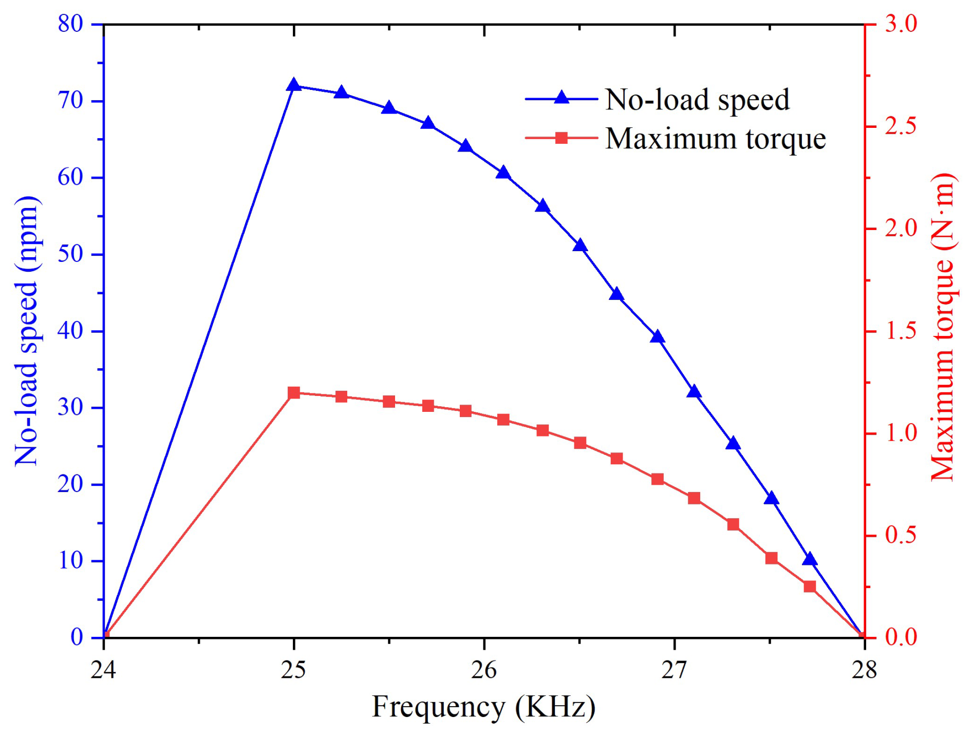
The simulation results of the output characteristics of the ultrasonic motor in MATLAB/Simulink are shown in Figs. 1 and 2. In Fig. 1, at an excitation frequency of 25 kHz, as the pre-pressure of the motor increases from 300 to 900 N, the no-load speed and torque first increase and then decrease, with the optimal output characteristics occurring at a pre-pressure of around 600 N. In Fig. 2, under a pre-pressure of 600 N, as the excitation frequency gradually increases from 24 to 28 kHz, the no-load speed and maximum torque of the motor first rapidly increase and then slowly decrease, reaching a peak at around 25 kHz.

3.1 Operating principle
The structure of an electro-hydraulic servo valve driven by an ultrasonic motor, as proposed in this paper, is shown in Fig. 3. It primarily consists of an ultrasonic motor, ball screw, slide valve, displacement sensor, and constraint components. The core of its structure lies in efficiently converting the high-frequency vibration energy of the ultrasonic motor into mechanical displacement control for the hydraulic servo valve, thereby achieving electromagnetic interference-free, high-precision flow and pressure regulation. This drive method offers significant advantages. Due to its non-electromagnetic drive characteristics, it effectively avoids the magnetic interference issues faced by traditional electromagnetic servo valves, providing a pure power source for the system. As the drive core, the ultrasonic motor utilizes the inverse piezoelectric effect of piezoelectric ceramics to convert high-frequency electrical signals into microscopic vibrations of the stator. These vibrations are then transmitted through friction coupling to drive the rotor's rotation or linear motion. Its non-electromagnetic drive characteristics eliminate the magnetic interference issues associated with traditional electromagnetic servo valves.

Figure 3Overall structure of an electro-hydraulic servo valve driven by an ultrasonic motor.
In the energy transmission path design, a three-stage energy conversion mechanism is employed: first, the inverse piezoelectric effect converts electrical signals into microscopic vibrations of the stator; second, the vibration energy is converted into mechanical energy through friction coupling between the stator and rotor; finally, a specially designed flexible guiding mechanism achieves motion transmission and error compensation. The transmission mechanism adopts a flexible hinge structure with preload adjustment functionality, ensuring gap-free transmission while also automatically compensating for dimensional tolerances caused by temperature changes.
In terms of overall design, the high-frequency characteristics of ultrasonic motors require minimizing the inertia of the transmission chain, while the high-pressure environment of hydraulic systems demands valve body materials with wear-resistant and corrosion-resistant properties. The design of the hydraulic valve body must be compatible with the drive characteristics. When the ultrasonic motor drives the valve core displacement, the hydraulic oil flow is regulated by adjusting the valve opening, thereby controlling the action of the actuator. This mechanism is controlled by an upper-level computer setting the excitation frequency, which is applied to the ultrasonic motor to generate output torque, driving the nut of the ball screw to rotate. The ball screw shaft is constrained circumferentially by a constraint component, allowing only axial displacement, thereby converting motor torque into axial force. This pushes the valve core to move axially, altering the overlap area between the valve core's U-shaped groove and the valve orifice, ultimately achieving high-precision control of fluid flow. A displacement sensor is located at the left end of the slide valve to collect the valve core displacement signal. Based on an adaptive fuzzy PID algorithm, closed-loop control is achieved, further enhancing the system's responsiveness and stability.
3.2 Construction of an Simcenter Amesim simulation model for a ball screw–slide valve
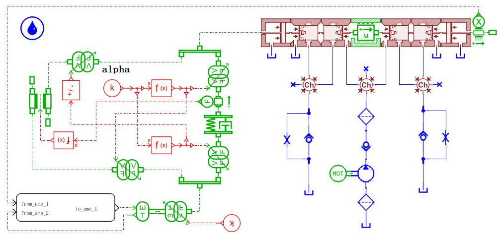
Based on Simcenter Amesim simulation software, during the process of establishing a simulation model for a ball screw, a two-port spring-damper model with linear motion capability is established on the basis of the contact stiffness and contact damping ratio, while neglecting the rolling friction between the ball and the screw. A simulation model of a three-position four-way spool valve is constructed using the minimum model unit from the basic hydraulic component design library. Figure 4 depicts the ball screw–spool valve simulation system built in Simcenter Amesim simulation software (Yuan et al., 2022).
When constructing the Simcenter Amesim simulation model of the ball screw valve core in this paper, a modular modeling approach was adopted. First, based on the mechanical structure and operating principle of the ball screw valve core, it was decomposed into multiple subsystems, such as the mechanical transmission module, fluid control module, and load characteristic module. Second, standard components from the hydraulic and mechanical libraries provided by Simcenter Amesim (such as mass blocks, spring dampers, and hydraulic valves) were used to build the basic model, which was then matched with actual parameters.
The simulation principle of the model primarily relies on multi-domain physical-system modeling methods, combined with mechanical dynamics and fluid mechanics theories. In Simcenter Amesim, the mechanical motion of the ball screw is simulated using a mass-spring-damper system, while the hydraulic characteristics of the valve core are realized through fluid models such as the throttling equation and flow–pressure relationships. This paper focuses on the coupled effect of valve spool displacement and hydraulic feedback and uses state equations to describe its dynamic response. Additionally, the simulation model may incorporate a PID control strategy to simulate the closed-loop regulation process in the actual system, ensuring that the simulation results closely align with real-world conditions.
The primary objectives of this simulation model include the following: (1) analyzing the dynamic characteristics of the ball screw valve spool under different operating conditions, such as step response and frequency characteristics; (2) optimizing valve spool structural parameters (such as lead and damping coefficients) and control strategies to enhance system stability and response speed; and (3) verifying the validity of the theoretical model and providing a reference basis for subsequent experimental research or engineering applications.
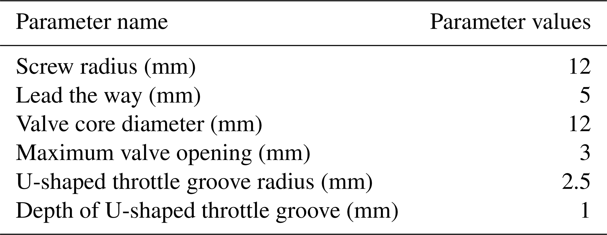
The main parameters required for the Simcenter Amesim simulation system of the ball screw–slide valve are shown in Table 1.
Table 1Characteristic parameters of the ball screw–spool valve system.
4.1 Overall structure of the controller
Adaptive fuzzy PID control, compared to conventional PID control, can perform fuzzy logic reasoning on changes in influencing factors and automatically adjust PID parameters to their optimal values, thereby enhancing the system's adaptability. The adaptive fuzzy PID control structure introduces a dual-loop feedback mechanism based on traditional PID control: the inner loop is a fuzzy reasoning system based on error e and error change rate ec, while the outer loop retains the traditional PID calculation framework. The core improvement lies in paralleling the fuzzy controller with the PID parameter adjustment module, forming a composite architecture of “fuzzy rule library + parameter dynamic corrector”. Specifically, this is manifested as follows: (1) a fuzzy interface design with two inputs (e and ec) and three outputs is adopted, where actual signals are mapped to the fuzzy domain through a quantization factor; (2) a parameter increment decoupling module is added to avoid overshoot issues caused by parameter coupling in traditional PID systems. This structure significantly enhances the system's adaptability to nonlinear time-varying operating conditions.
The core working principle of the adaptive fuzzy PID controller is to perform fuzzy logic reasoning on the input deviation signal e(t) and its derivative , and to adjust the three PID parameters in real time, thereby further reducing the overshoot and adjustment time of the entire system. Figure 5 shows the structure of the adaptive fuzzy PID controller designed for the ultrasonic-motor-driven electro-hydraulic servo valve (Liao et al., 2024).

The innovation of this scheme lies in its dynamic parameter tuning mechanism: by establishing a fuzzy rule matrix with e and ec as inputs (e.g., the Kp rule table uses a 7 × 7 Mamdani-type inference), it achieves online self-calibration of PID parameters. Key technical breakthroughs include the following:
-
A dynamic allocation algorithm for error gradient membership functions is proposed that automatically switches parameter adjustment strategies based on the magnitude of ; when the error is large, it reinforces the proportional action to suppress steady-state error, and when the error is small, it enhances the integral action to improve accuracy.
-
An anti-integral saturation logic is introduced that freezes the integral term when ec exceeds the threshold, addressing the windup issue of traditional PID.
Compared to traditional PID, the advantages of this method's control logic are concentrated in the three following aspects:
-
Enhanced robustness. By encoding expert experience into fuzzy rules, the method possesses adaptive compensation capabilities for unmodeled dynamics (such as the nonlinear friction of ball screw drives).
-
Optimized dynamic performance. Based on an ec-driven differential lead control strategy, damping torque is pre-generated in the phase lag loop.
-
Improved disturbance rejection capability. The parameter tuning process has memory characteristics, automatically adjusting fuzzy rule weights based on historical error distributions.
These advantages make it particularly suitable for servo control applications in high-precision mechatronic systems.
4.2 Design of the adaptive fuzzy PID controller
The entire ultrasonic-motor-driven electro-hydraulic servo valve system design encompasses (1) the adaptive fuzzy PID controller component in MATLAB/Simulink and the modeling of ultrasonic motors and (2) the modeling of ball screws and hydraulic spool valves in the Simcenter Amesim environment. The adaptive fuzzy PID controller is designed using the Fuzzy Logic Toolbox in MATLAB (Liang et al., 2023).
The general approach for a conventional PID controller is as follows:
The host computer samples the analog signal from the displacement sensor periodically through analog-to-digital converter, thus necessitating the use of a discrete control algorithm by the controller. Discretizing the above formula yields the following:
Here, KP represents the proportional coefficient; represents the integral coefficient; KD=KPTD represents the differential coefficient; T represents the sampling period; k represents the sampling sequence number; and e(k) and e(k−1) represent the error values at the kth and (k−1)th moments, respectively.
The adaptive fuzzy PID controller takes two inputs: input deviation E and deviation change rate EC. The basic domains of these two inputs are normalized to a discrete domain of [−6, 6], with seven variable value levels selected: . The three outputs of PID parameter variations ΔKP, ΔKI, and ΔKD are also divided into seven fuzzy intervals, , with corresponding domains of [−6, 6]. Both input and output employ triangular membership functions, which are beneficial for improving resolution and control sensitivity.
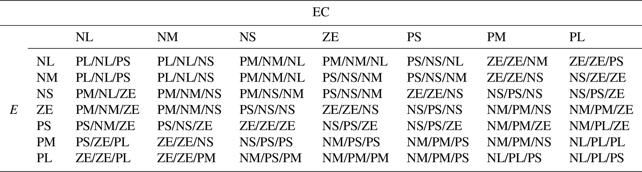
After fuzzifying the inputs and outputs, they need to be linked together using fuzzy rules. Based on actual control experience, the fuzzy rules for the parameter adjustment quantities ΔKP, ΔKI, and ΔKD are summarized in Table 2.
Due to the fuzzy quantity results obtained from the fuzzy decision-making process and the need for precise quantities in controlling the controlled object, it is necessary to map the results of fuzzy inference from fuzzy sets to ordinary sets. Common defuzzification methods include the coefficient weighted-average method and the centroid method. The centroid method comprehensively considers relevant information about fuzzy quantities, is intuitive and reasonable, and is easier to implement (Yang et al., 2022). Therefore, the centroid method is adopted in this system for defuzzification. The obtained changes in ΔKP, ΔKI, and ΔKD are applied to the PID controller through formula (6):
Here, qP, qI, and qD are the adjustment factors for parameters KP, KI, and KD, respectively.
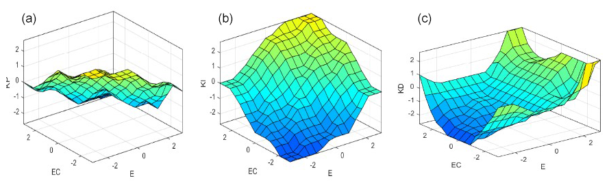
Figure 6 shows the spatial observation surfaces of the output variables ΔKP, ΔKI, and ΔKD, respectively. It can be observed that the smoothness of the spatial surfaces is good, indicating that the output is nearly continuous. Therefore, the performance of the fuzzy control system is good.
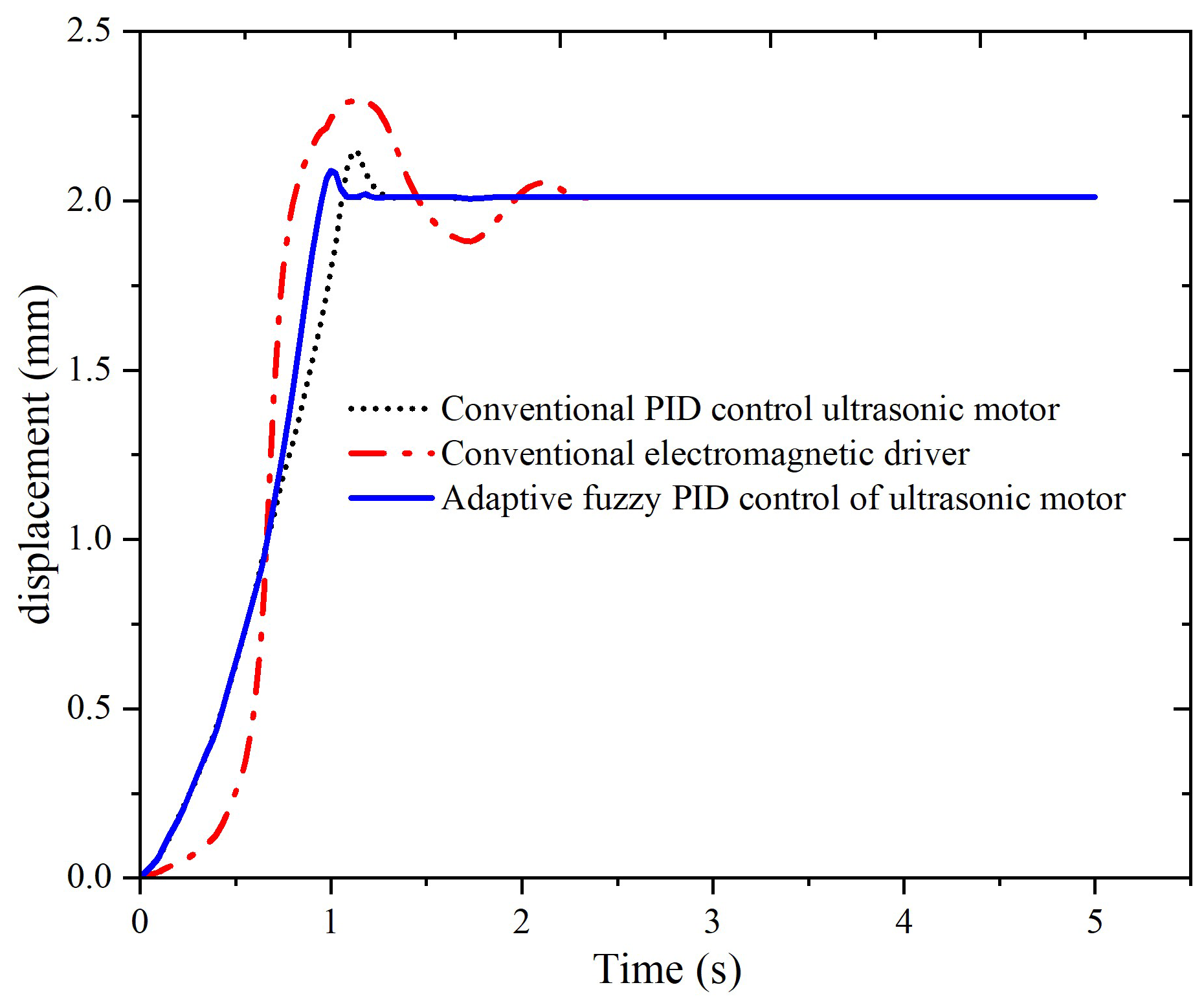
Simulation analysis was conducted on three scenarios: conventional electromagnetic drive, conventional PID-controlled ultrasonic-motor drive, and ultrasonic-motor drive with adaptive fuzzy PID control. The trial-and-error method was used to determine the parameters as KP0=4.3, KI0=0.15, and KD0=0.1. A step signal with an amplitude of 2 was applied to simulate a valve core displacement of 2 mm. The simulation duration was set to 5 s with a step size of 0.01 s.
As can be seen from Fig. 7, under the influence of a step signal, the conventional electromagnetic drive exhibits an overshoot of 15 % in the displacement of the spool valve core and a regulation time of 2.3 s. The main reason for this is that the electromagnetic drive lacks self-locking characteristics and can only slow down through reverse electromagnetic force, resulting in significant inertia and poor control accuracy. For the spool valve driven by an ultrasonic motor under conventional PID control, the overshoot in the displacement of the spool valve core is reduced to 8 % and the regulation time is shortened to 1.3 s. After the overshoot, the self-locking and fast-response characteristics of the ultrasonic motor enable the system to quickly respond and compensate, resulting in a more ideal control effect compared to the electromagnetic valve. When fuzzy adaptive PID control is applied, the overshoot is reduced to 4 % and the regulation time is shortened to 1.1 s.
To further compare the control performance of conventional electromagnetic drive, conventional PID-controlled ultrasonic-motor drive, and ultrasonic-motor drive with adaptive fuzzy PID control, a simulated step signal interference was applied to the control signal after the spool valve core stopped moving (at 3 s), resulting in the simulation response curve shown in Fig. 8.
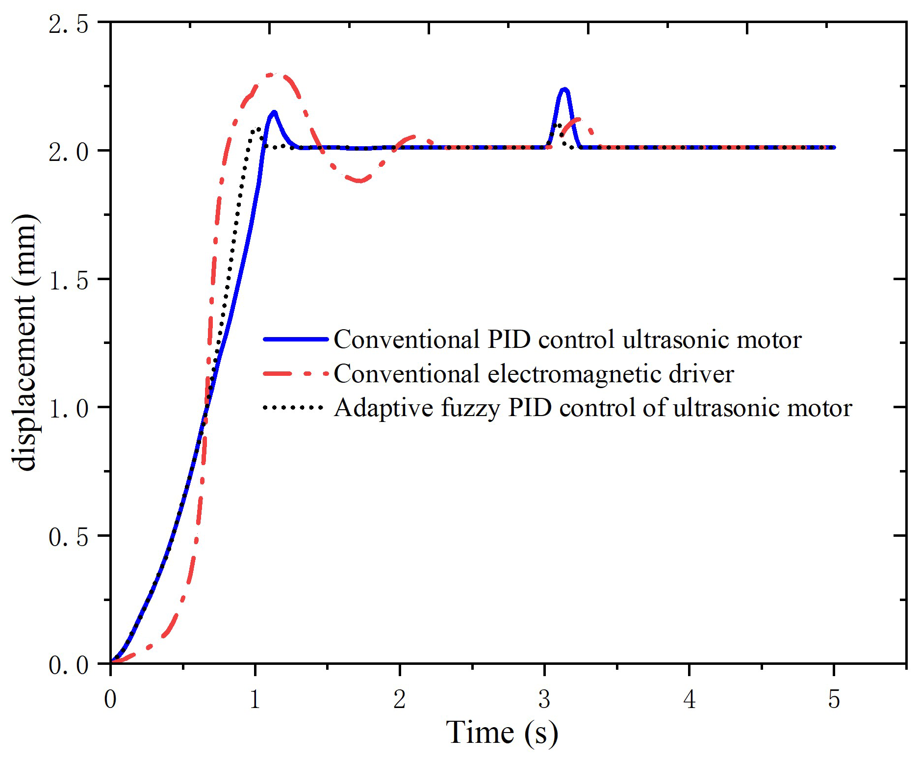
As can be seen from Fig. 8, after being subjected to a step signal with interference, the conventional electromagnetic drive produced an overshoot of 6 % with a recovery time of 0.4 s. When subjected to the interference signal, the conventional PID-controlled ultrasonic-motor drive exhibited an increased overshoot of 10 % compared to the electromagnetic drive, yet it recovered to stability in as little as 0.2 s. Conversely, the adaptive fuzzy PID-controlled ultrasonic-motor drive produced an overshoot of 6 % after being subjected to the interference signal and recovered to stability in 0.1 s. In terms of flow control accuracy for the spool valve, the adaptive fuzzy PID-controlled ultrasonic-motor drive demonstrates superior performance.
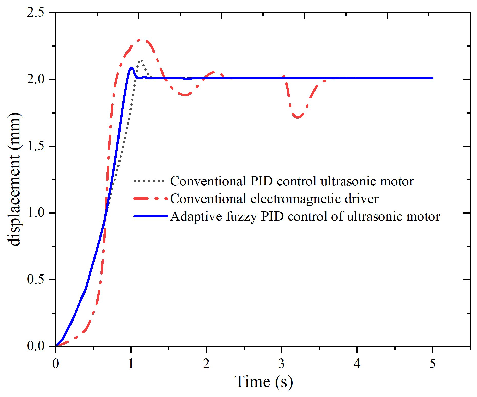
In addition, by altering the load after the system stabilizes, we further analyzed the stability of the three drive control methods. After the spool valve core stopped moving (at 3 s), we doubled the load and conducted a simulation, obtaining the simulation curve graph shown below.
As can be seen from Fig. 9, when the hydraulic load suddenly doubles to 600 N at the third second after stabilization, the spool displacement of the conventional electromagnetic-driven spool valve fluctuates to 1.7 mm and recovers stability after 0.5 s. However, for the spool valves driven by conventional PID control ultrasonic motors and adaptive fuzzy PID control ultrasonic motors, the spool displacement remains unchanged after the load doubles. The stable spool displacement formed by electromagnetic driving is dynamically stabilized by the electromagnetic force, hydraulic pressure, and spring force. Changes in load lead to changes in hydraulic pressure, breaking the dynamic stability. The system restores stability by adjusting the electromagnetic force. After the spool stabilizes, due to its self-locking characteristics, the increase in load is much smaller than the self-locking force of the ultrasonic motor, which cannot break the stability of the spool.
The conventional electro-hydraulic servo valve, driven by an electromagnet, exhibits poor dynamic characteristics and low flow control accuracy. In response to this situation, research has been conducted on ultrasonic-motor-driven electro-hydraulic servo valves, and adaptive fuzzy PID algorithms have been adopted to optimize control. The research results on the dynamic characteristics of the system indicate the following:
-
Under adaptive fuzzy PID control, the ultrasonic-motor-driven electro-hydraulic servo valve system exhibits an 11 % reduction in overshoot and a 52 % reduction in adjustment time compared to conventional electromagnetic drives.
-
Under adaptive fuzzy PID control, after the spool valve core stops moving (at 3 s), when subjected to a disturbed step signal, the system's overshoot is 6 % and the recovery time is shortened by 25 %.
-
Under adaptive fuzzy PID control, after the spool valve core stops moving (at 3 s), even when the load suddenly doubles, the servo valve system driven by the ultrasonic motor remains unaffected.
-
Under adaptive fuzzy PID control, the ultrasonic-motor-driven electro-hydraulic servo valve system exhibits superior robustness and anti-interference capabilities, enabling precise control of valve spool displacement and, thus, being more suitable for high-precision flow control.
In future research, the following areas can be further explored: first, more complex types of disturbances can be introduced to comprehensively evaluate the robustness of the system; second, intelligent optimization algorithms can be combined to dynamically adjust fuzzy rules and PID parameters to improve adaptive accuracy; in addition, the engineering applicability of the algorithm should be verified through hardware-in-the-loop (HIL) simulation and actual system experiments, and the anti-interference performance indicators should be quantified. To enhance the system's interference resistance, future research can focus on the following optimizations: in terms of control structure, a disturbance observer (DOB) can be integrated to achieve feed-forward compensation for disturbances, reducing reliance on feedback regulation; in terms of parameter adaptation, reinforcement learning can be employed for online optimization of the fuzzy PID adjustment strategy.
Data are available from the authors upon request.
RN discussed and decided on the methodology of the study and prepared the manuscript. BZ contributed to the prototype and test. ZP contributed to the model building.
The contact author has declared that none of the authors has any competing interests.
Publisher's note: Copernicus Publications remains neutral with regard to jurisdictional claims made in the text, published maps, institutional affiliations, or any other geographical representation in this paper. While Copernicus Publications makes every effort to include appropriate place names, the final responsibility lies with the authors. Views expressed in the text are those of the authors and do not necessarily reflect the views of the publisher.
This research was partly supported by the Zhejiang Province Postdoctoral Research Fund Project (project no. ZJ2023130) and the China High-Level Talent Research Start-up Fund (project no. jit-6-202117).
This research has been supported by the National Natural Science Foundation of China (grant no. 52075232).
This paper was edited by Haitong Liang and reviewed by two anonymous referees.
Chen, L., Zhang, C., Jin, B., and Yuan, T.: Simulation and experimental research on steady flow force compensation for a servo proportional valve, Flow Measurement and Instrumentation, 94, 854–866, https://doi.org/10.1016/j.flowmeasinst.2023.102457, 2023.
Fan, Z., Fan, J., and Yu, X.: An indirect flow measurement based high-precision slide valve grinding mechanism for hydraulic servo valve, Measurement Sience and Technology, 34, 77–84, https://doi.org/10.1088/1361-6501/ac94ee, 2023.
Gao, B., Zhang, W., and Zheng, L.: Research on High-Precision Position Control of Valve-Controlled Cylinders Based on Variable Structure Control, Machines, 11, 645–654, https://doi.org/10.3390/machines11060623, 2023.
Gao, Q., Li, L., and Zhu, Y.: Performance analysis of a high-frequency two-stage proportional valve piloted by two high-speed on/off valve arrays, Transactions of the Canadian Society for Mechanical Engineering, 13, 399–408, https://doi.org/10.1139/tcsme-2024-0079, 2024.
Guo, K., Li, M., and Shi, W.: Adaptive Tracking Control of Hydraulic Systems With Improved Parameter Convergence, IEEE Transactions on Industrial Electronics, 69, 7140–7150, https://doi.org/10.1109/TIE.2021.3101006, 2022.
Guo, X.: Research on electric proportional valve driven by ultrasonic motor based on patch bending vibration mode, Master's thesis, Harbin Institute of Technology, https://doi.org/10.7666/d.D240489, 2012.
Huang, Y.: Research on pneumatic control valve driven by ultrasonic motor. Master's thesis, Harbin Institute of Technology, https://doi.org/10.7666/d.D266808, 2010.
Li, N., Dong, C., Wei, L., and Ji, H.: Oscillation Suppression Method of Digital Proportional Valve Based on Fuzzy Intelligent PID Control, Applied Sciences-Basel, 14, 254–263, https://doi.org/10.3390/app142311177, 2024.
Liang, Y., Pan, S., and Chen, L.: Design of Optoelectronic Tracking Platform Driven by Ultrasonic Motor with a Novel Limiter, Micromachines, 14, 468–480, https://doi.org/10.3390/mi14112067, 2023.
Liao, Y., Zhao, W., Feng, J., and Lian, Z.: Optimization of the Control Performance of a Novel 3/2 Water Proportional Directional Valve With a Special Position Following Servo Mechanism, IEEE-Asme Transactions on Mechatronics, 29, 3391–3400, https://doi.org/10.1109/TMECH.2023.3343398, 2024.
Ling, M. and Wang, J.: Nonlinear coupled dynamic effects in flexure-amplified piezoelectric valve with an analytical transfer function, Proceedings of the Institution of Mechanical Engineers Patr C-Journal of Mechanical Engineering Science, 237, 359–373, https://doi.org/10.1177/09544062221121989, 2023.
Liu, C., Wang, A., Li, X., and Li, X.: Thermal Load Model of a Proportional Solenoid Valve Based on Random Load Conditions, Sensors, 23, 408–419, https://doi.org/10.3390/s23239474, 2023.
Liu, L., Shen, G., and Wang, W.: Neural adaptive dynamic surface control for position tracking of electrohydraulic servo systems based on extended state observer, Proceedings of the Institution of Mechanical Engineers Part I-Journal of Systems and Control Engineering, 238, 1535–1555, https://doi.org/10.1177/09596518241246825, 2024a.
Liu, Y., Wang, S., Qi, J., and Wang, X.: Study on the Influence of Dynamic Characteristics of Servo Valve on Coupling Vibration of Cold Rolling Mill, International Journal of Precision Engineering and Manufacturing, 25, 1577–1570, https://doi.org/10.1007/s12541-024-01017-4, 2024b.
Mi, J. and Huang, G.: Dynamic Prediction of Performance Degradation Characteristics of Direct-Drive Electro-Hydraulic Servo Valves, Applied Sciences-Basel, 13, 7231–7238, https://doi.org/10.3390/app13127231, 2023.
Milecki, A., Jakubowski A., and Kubacki, A.: Design and Control of a Linear Rotary Electro-Hydraulic Servo Drive Unit, Applied Sciences-Basel, 13, 135–416, https://doi.org/10.3390/app13158598, 2023.
Niu, R., Guo, Y., and Liu, J.: Design and experimental study of electromagnetic clutch-type variable pre-pressure ultrasonic motor, AIP Advances, 13, 589–602, https://doi.org/10.1063/5.0172497, 2023.
Niu, R., Guo, Y., Wu, G., and Liu, J.: Research on mechanical analysis and optimal design of electromagnetic variable pre-pressure ultrasonic motor, AIP Advances, 15, 246–259, https://doi.org/10.1063/5.0245519, 2025.
Qiao, S., Quan, L., Hao, Y., and Ge, L.: Design and characteristic research of a novel electromechanical-hydraulic hybrid actuator with two transmission mechanisms, Frontiers of Mechanical Engineering, 18, 289–296, https://doi.org/10.1007/s11465-022-0735-x, 2023.
Wang, S., He, L., and Albini, A.: A Magnetorheological Elastomer-Based Proportional Valve for Soft Pneumatic Actuators, Advance Intelligent Systems, 5, 480–488, https://doi.org/10.1002/aisy.202200238, 2023.
Wang, W., Liu, S., and Zhao, D.: Low-Complexity Error-Surface Prescribed Performance Control for Nonlinear Uncertain Single-Rod Electro-Hydraulic System, IEEE Transactions on Control Systems Technology, 32, 2402–2409, https://doi.org/10.1109/TCST.2024.3390165, 2024.
Xiang, P., Meng, B., and Huang, Y.: Research on a large torque surface-mounted magnetic screw mechanism and its application on 2D flow valve, Flow Measurement and Instrumentation, 16, 577–588, https://doi.org/10.1016/j.flowmeasinst.2024.102807, 2024.
Yang, L., Huan, Y., Ren, W., and Ma, C.: Position control method for ultrasonic motors based on beat traveling wave theory, Ultrasonics, 125, 981–989, https://doi.org/10.1016/j.ultras.2022.106793, 2022.
Yang, M., Lian, K., Luo, S., and Yu, C.: Simulation analysis and optimization of pilot type electro-hydraulic proportional directional valve based on multi field coupling, Flow Measurement and Instrumentation, 100, 546–553, https://doi.org/10.1016/j.flowmeasinst.2024.102726, 2024.
Yao, Y.: Research on incremental digital flow valve based on ultrasonic motor. Master's thesis, Kunming University of Science and Technology, https://xueshu.baidu.com/usercenter/paper/show?paperid=9d7342b0da5d9f7299300d873650a724&site=xueshu_se (last access: 17 November 2024), 2017 (in Chinese).
Yuan, X., Ling, H., Chen, J., and Feng, Y.: A dynamic modelling method for an electro-hydraulic proportional valve combining multi-systems and moving meshes, Journal of the Brazilian Society of Mechanical Sciences and Engineering, 44, 447–454, https://doi.org/10.1007/s40430-022-03603-x, 2022.
Yuan, X., Shi, S., Wang, C., and Wei, L.: Dynamic modeling method for an electro-hydraulic proportional valve coupled mechanical-electrical-electromagnetic-fluid subsystems, Journal of Magnetism and Magnetic Materials, 12, 842–853, https://doi.org/10.1016/j.jmmm.2023.171312, 2023.
Zhao, R., Chai, W., and Zhang, Y.: Dynamics and experimental study of a novel proportional directional valve with displacement feedback groove controlled by high-speed switching valves, Flow Measurement and Instrumentation, 100, 897–906, https://doi.org/10.1016/j.flowmeasinst.2024.102711, 2024.
Zhang, J., Pan, X., and Guo, J.: Analysis of the static and dynamic characteristics of the electro-hydraulic pressure servo valve of robot, Scientific Reports, 13, 879–886, https://doi.org/10.1038/s41598-023-42860-1, 2023.
Zhu, C., Meng, B., Wang, L., and Xu, H.: Full circumferential reluctance maglev coupling for 2D proportional flow rate valve: Design, modelling and experimental validation, Flow Measurement and Instrumentation, 95, 964–970, https://doi.org/10.1016/j.flowmeasinst.2023.102510, 2023.
- Abstract
- Introduction
- Analysis of the dynamic characteristics of ultrasonic motors
- Structural design of an electro-hydraulic servo valve driven by an ultrasonic motor
- Adaptive fuzzy PID control
- Overall simulation analysis based on adaptive fuzzy PID control
- Conclusions
- Data availability
- Author contributions
- Competing interests
- Disclaimer
- Acknowledgements
- Financial support
- Review statement
- References