the Creative Commons Attribution 4.0 License.
the Creative Commons Attribution 4.0 License.
 | 10 Nov 2026
Residual-stress distribution in gear journal shafts induced by mechanical roll hardening
Xinbo Zhang
Xiuyang Xia

Residual tensile stresses in the surface layer of machined 30CrMoA gear journal shafts readily promote fatigue crack initiation and degrade in-service reliability. To mitigate these stresses, this study investigates a localized mechanical rolling-hardening process for the journal diameter. The residual-stress distribution in the rolled journal is characterized by combining finite-element simulation with X-ray diffraction residual-stress measurements, and the effects of key process parameters, namely rolling depth, workpiece rotational speed, and feed rate, on the magnitude of residual compressive stress and the depth of the strengthened layer are systematically examined. A response surface methodology based on central composite design is then employed to develop predictive models for the residual stress and layer depth, thereby enabling multi-objective optimization of the rolling process. The results demonstrate that mechanical rolling generates a stable, graded residual compressive-stress field within the localized surface layer, with the peak compressive stress occurring at approximately 0.20 mm beneath the surface, while the underlying matrix exhibits only weak equilibrating tensile stresses. Among the process parameters, rolling depth exerts the most significant influence, while pronounced coupling and saturation effects between parameters are also observed. An optimal parameter combination is determined and experimentally validated: under the optimized conditions, both the magnitude of the residual compressive stress and the depth of the strengthened layer are markedly increased, while the deviation between the simulated and experimental results remains below 8.0 %. The established parametric model accurately predicts the localized residual-stress state of rolled 30CrMoA journals, thereby providing theoretical guidance and technical support for the surface rolling strengthening of gear journals.
- Article
(2885 KB) - Full-text XML
- BibTeX
- EndNote


As the core component for power transmission in prime movers, gears are subject to extremely stringent requirements for both manufacturing precision and service performance. Due to the periodic nature of meshing loads, the shaft journal is subjected to large-amplitude alternating impact forces over extended periods, readily inducing bending and torsional deformations. Under sustained cyclic bending stresses, the material progressively accumulates fatigue damage, eventually leading to crack initiation, which severely compromises the reliability and service life of the gear transmission system (Luo et al., 2023; Aliakbari et al., 2022a, b; Singh and Sengar, 2021). Driven by rapid advances in computational power, finite-element simulation has matured into an indispensable tool for the structural design of gear shaft systems under fatigue loading. Nevertheless, relying solely on structural optimization to enhance fatigue performance presents distinct limitations: on the one hand, the local optimization space available at the gear shaft journal is inherently constrained; on the other hand, adjustments to structural parameters will trigger dimensional chain variations in associated mating components, resulting in broad-ranging impacts that are difficult to reconcile with practical manufacturing constraints. Consequently, under current technological conditions, achieving fatigue strengthening through the refinement of manufacturing processes and optimization of machining parameters remains a more viable technical pathway (Aliakbari et al., 2022; Xu et al., 2025; Fu et al., 2026).
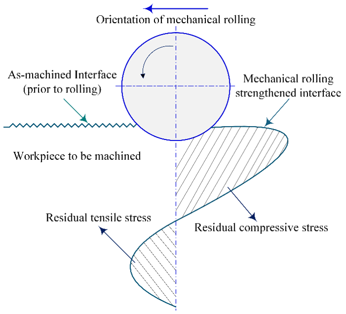
Currently, numerous surface strengthening methods have been developed for engineering practice, each possessing specific applicable operating conditions and inherent limitations (Ma et al., 2024). Surface rolling strengthening, as an effective chipless surface treatment technology, applies reciprocating rolling pressure to the component surface via specially designed rolling tools (commonly fabricated from quenched steel, cemented carbide, or ruby, with geometries encompassing rollers, balls, and wheels) (the strengthening process is illustrated in Fig. 1) (Li et al., 2023; Zhou et al., 2023a, b; Španiel et al., 2021). This process significantly reduces surface roughness while introducing a favorable residual compressive-stress field into the surface layer, thereby concurrently improving the corrosion, wear, and fatigue performance of the component, demonstrating excellent engineering applicability (Kluz et al., 2021; Nguyen et al., 2022; Noronha et al., 2024).
As a surface modification technique, surface rolling strengthening has attracted considerable attention and has been widely employed to enhance the fatigue performance of mechanical components. The Internal Combustion Engine Research Institute of Tianjin University employed rolling processes to strengthen the gear shaft journals of 370Q and 376Q diesel engines. The results demonstrate that the fatigue limit of the rolling-strengthened journals increased by 92.3 % relative to the untreated journals, while the safety factor was nearly doubled (Heikebrügge et al., 2022a, b). Liuzhou Nanfang Automotive Cylinder Liner Factory and Henan Yingwei Dongfeng Machinery Manufacturing Co., Ltd. conducted rolling strengthening experiments on automotive cylinder liners and hub axle tubes, respectively, confirming that this technology significantly improves product yield rates and enhances fatigue performance (Morrev and Gordon 2018; Pertoll et al., 2024). It was reported that the stress corrosion cracking strength of 300M steel after strengthening treatment could be elevated to the alloy's yield strength level, with increased fracture threshold values, thereby effectively enhancing resistance to stress corrosion cracking (Fonseca and Faria 2019). The Academy of Armored Force Engineering investigated rolling strengthening of machined surfaces on heavy-duty components following surfacing repair. Their findings revealed that rolling the surfacing layer with specific process parameters could generate nanoscale grain structures within the surface layer, improving surface hardness, wear resistance, and residual-stress states (Kinner-Becker et al., 2020; Bialowas et al., 2023).
Regarding the control of surface microstructure and stress state, the surface rolling treatment of LZ50 steel was investigated, and it was found that this process increases the hardness of the surface layer and introduces high-level residual compressive stresses (Kinner-Becker and Sölter, 2023). The synergistic effect of enhanced surface hardness and residual compressive stress effectively suppresses microcrack initiation and propagation and mitigates the accelerating effect of short-crack colonies on crack growth, thereby improving the local fatigue resistance of the material (Kinner-Becker et al., 2021). The very-high-cycle fatigue behavior of high-carbon chromium-bearing steel was studied, demonstrating that, in the high-stress, low-life regime, cracks in both treated and untreated specimens were initiated from the surface (Fonseca and Faria, 2018). However, the presence of surface residual compressive stress after rolling led to increased fatigue strength.
In the low-stress, high-life regime, crack origins in untreated specimens were located in the subsurface, whereas, in treated specimens, they shifted to interior regions devoid of residual compressive stresses and hardened layers, resulting in significant fatigue strength improvement (Kumar et al., 2021). X-ray diffraction was used to characterize the surface residual-stress distribution in the rolled AA6110-T6 aluminum alloy and its influence on fatigue performance. The residual-stress relaxation behavior under varying thermal conditions and its underlying mechanisms were analyzed (Dänekas et al., 2022; Schubnell et al., 2022). The research demonstrates that rolling strengthening establishes a residual compressive-stress zone of appreciable depth within the specimen surface layer, effectively reducing the operational stress level during actual service, thereby suppressing fatigue crack nucleation and propagation in the surface layer and enhancing material fatigue life (Reggiani and Olmi, 2019; Heikebrügge et al., 2022a, b). Additionally, rolling treatment improves specimen surface quality, reduces surface roughness, renders machined surface profiles smooth and continuous, effectively mitigates stress concentration, and diminishes the detrimental influence of geometric notches on fatigue strength (Dos et al., 2021; Martins et al., 2023). A stochastic rack vehicle–track dynamic model incorporating nonlinear wheel–rail and gear–rack contacts was established to reveal the terrain–wind–vehicle coupling mechanisms under pulsating crosswinds. The results demonstrate that pulsating crosswinds degrade operational stability and gear–rack engagement, with the adverse effects intensifying as the gradient increases; the safe wind speed thresholds decrease from 29 to 22.5 m s−1 as the gradient rises from 100 ‰ to 200 ‰ (Chen et al., 2025).
In summary, rolling strengthening exhibits significant efficacy in improving surface microstructure, optimizing stress distribution states, and enhancing surface integrity, constituting an effective fatigue-strengthening methodology.
2.1 Experimental materials
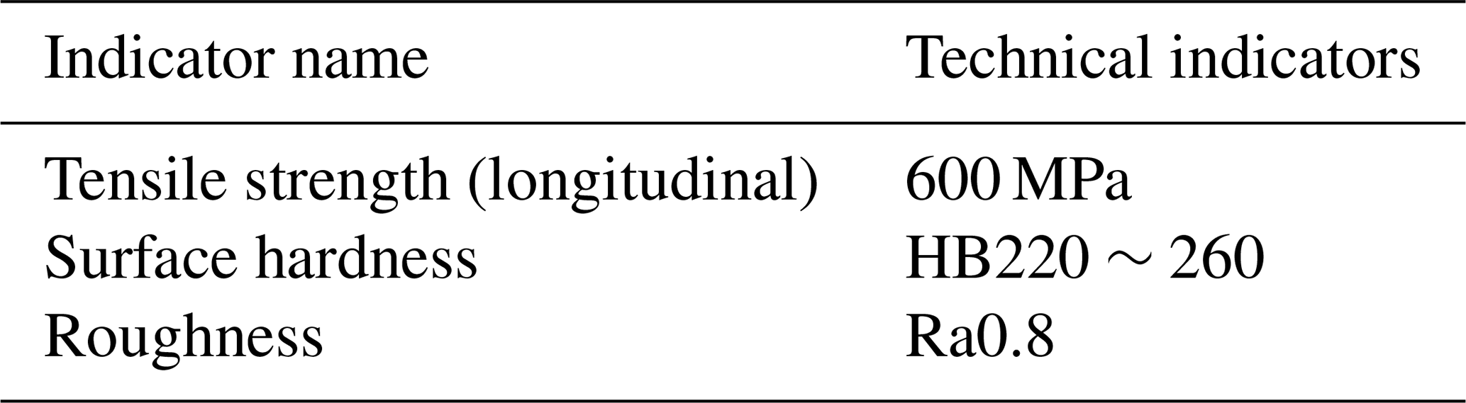
A 30CrMoA steel shaft (Φ50×200 mm) is used in this study, with its chemical composition and mechanical properties listed in Tables 1 and 2, respectively. In these tables, E is the elastic modulus of the material, σ0.2 represents the yield strength, σb designates the tensile strength, v represents Poisson's ratio, ρ denotes the density, u depicts the coefficient of friction, and C describes the specific heat capacity.
Table 1Chemical composition of 30CrMoA steel used in testing (mass fraction, %).


Taking a large, high-precision gear drive shaft as the prototype and considering the costs and duration of the tests under the principle of material similarity, process experiments and measurements are conducted on scaled-down specimens fabricated from the same material with the same initial heat-treated condition. The tempering specifications for the mechanically rolled specimens are listed in Table 3.
2.2 Mechanism of mechanical roll-forming strengthening
Rolling is essentially an elastoplastic contact problem. Once the maximum contact pressure between the roller and the workpiece exceeds the material's yield strength, irreversible plastic deformation occurs, producing a work-hardened surface layer and a residual compressive-stress field. According to Hertz's line contact theory (Łach et al., 2024), the contact half-width b is given by the following:
where P is the normal rolling force, R denotes the roller radius, L is the effective contact length of the roller, and E* is the equivalent elastic modulus. Among these,
where E1 and E2 are the moduli of elasticity of the roller and the workpiece, respectively, while v1 and v2 represent Poisson's ratios of the roller and the workpiece, respectively.
The maximum contact pressure is as follows:
The pressure distribution is semi-elliptical and perpendicular to the roller's axis.
In the above, x represents the lateral distance from the center of contact.
According to the Tresca (maximum shear stress) criterion, initial yielding occurs when the rolling pressure reaches the critical value PY:
where σY represents the uniaxial yield strength of the material.
When P<PY, the contact zone is in a fully elastic state, and Hertz's theory can be applied; when P>PY, the material yields.
The entire rolling process is divided into elastic, elastoplastic, and fully plastic stages. Rolling induces a certain amount of stress in the journal. To introduce residual stresses into the journal's surface layer that can counteract the thermal stresses and centrifugal forces generated during operation, the applied stress reaches the yield limit, that is, P>PY, and plastic deformation occurs. Elastoplastic problems fall under the category of material nonlinearity (Caddemi, 1994).
The strain formula for plastic deformation is as follows:
where dεe and dεp are the elastic strain increment and the plastic strain increment, respectively. dεe obeys Hooke's law, which states
where [De] represents the elastic matrix of the material, and {dσ} represents the stress increment. {dεe} follows the flow law, which is
where F represents the loading surface. The von Mises yield criterion is adopted. The incremental stress–strain relationship for the perfectly elastoplastic model is then expressed as follows:
Since rolling involves only localized microplastic deformation, it is assumed that the process does not alter the overall elastic properties of the workpiece. For both single-roller and roller column rolling, the mechanical response can be idealized as a plane strain problem. As the roller–workpiece contact can be approximated as line contact, the rolling force is modeled as a concentrated line load. Based on the solution to the Boussinesq–Flamant problem, the internal stress field in the workpiece can then be expressed as follows (Xu et al., 2025):
where ps is the concentrated pressure at the centerline in the Boussinesq–Flamant problem, which is related to the rolling pressure p as
where a is the equivalent contact length of the rolling action of a roller or roll.
We substitute Eqs. (10) through (13) into the von Mises yield criterion:
We obtain
where σs is the von Mises yield stress of the workpiece, and v is Poisson's ratio of the workpiece; therefore, during the rolling process, microplastic deformation occurs within a cylinder subjected to a linear load. Setting θ=0 yields the relationship between the depth of microplastic deformation and the rolling force in roller or roll-forming processes:
For ball rolling, the contact between the ball and the workpiece can be approximated as point contact, and the rolling force is likewise modeled as a concentrated force. Based on the Boussinesq solution, the stress components in the workpiece are given as follows:
Substituting Eqs. (17) through (22) into the von Mises yield criterion and setting y=0 and z=0 yields the following relationship between the microplastic-deformation depth at the axis and the rolling force:
According to fracture mechanics, a surface crack or crack-like defect propagates under cyclic loading only when the stress intensity factor at its tip reaches the critical value of the material. In the presence of a mean stress, the critical stress intensity factor range can be expressed as follows (Luo et al., 2023; Ma et al., 2024):
where R represents the average stress under alternating loads.
Since residual compressive stress counteracts the mean stress induced by external cyclic loading, it reduces the effective stress intensity factor range ΔK experienced by the component. The reduction in R, in turn, raises the critical stress intensity factor ΔKth at which crack propagation initiates. Consequently, under a given cyclic loading condition, a crack that would otherwise propagate requires a higher applied stress to grow in the presence of residual compressive stress owing to the elevated ΔKth. This mechanism accounts for the beneficial effect of residual compressive stress on the fatigue strength of cracked components.
2.3 Mechanical-roll-forming test
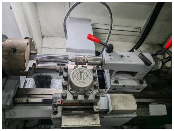
The rolling experiments were conducted on a CAK3665 CNC lathe equipped with a variable-frequency stepless speed-regulated spindle, offering a rotational speed range of 20–3000 r min−1. The maximum traveling speeds of the X and Z axes are 220 and 650 mm, respectively, with corresponding rapid traverse rates of 3.8 and 7.8 m min−1. The positioning repeatability is 0.012 mm for the X axis and 0.016 mm for the Z axis, meeting the stringent accuracy requirements for controlling the rolling depth, workpiece rotational speed, and feed rate examined in this study.
During the rolling process, the rolling tool is mounted on the X-axis slide of the CNC lathe through a tool holder, and the roller is pressed against the gear journal surface with a predetermined penetration depth. The workpiece rotates with the spindle at a constant rotational speed, while the rolling tool traverses axially along the journal at a preset feed rate, generating a continuous helical rolling track on the journal surface. Under the applied static load, the rolling elements exert a normal contact pressure on the journal surface; once this pressure exceeds the yield strength of the material, directional plastic flow is induced in the surface layer. The penetration depth is precisely controlled by the CNC system and directly governs the stress level and the extent of plastic deformation within the contact zone.
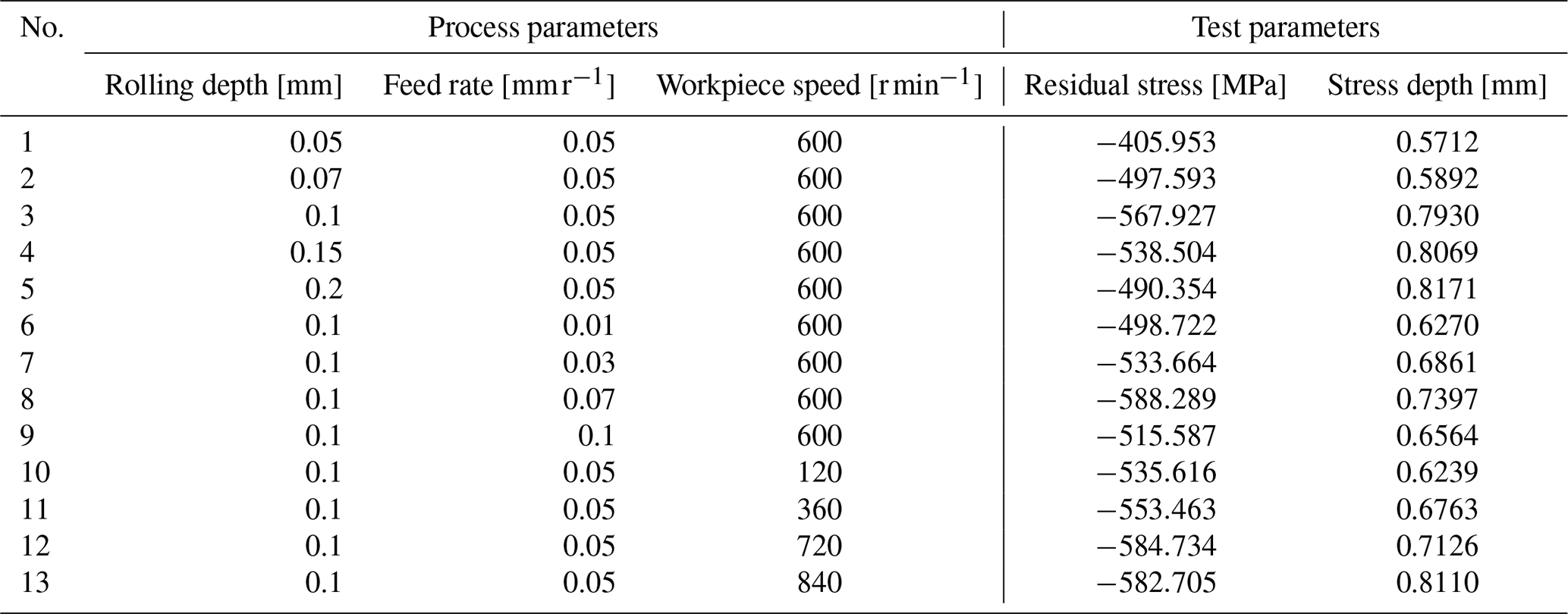
X-ray diffraction (XRD) measurements are performed using a PROTO LXRD residual-stress analyzer to determine the residual stresses in the surface layer of the specimens. A PROTO 8818-V3 electropolishing device is employed for successive layer-by-layer material removal; in combination with the XRD measurements, the residual stress at successive depths is thereby determined, allowing the through-depth residual-stress distribution to be characterized. A deep-focus microscope is used to examine the surface microstructure of the specimens before and after rolling, from which the deformed layer thickness and grain morphology under different process parameters are obtained; the features of rolling-induced surface plastic deformation and grain refinement are then analyzed based on these images. To investigate the effects of rolling depth, feed rate, and workpiece rotational speed on the surface residual stress and the depth of the stress-affected layer after mechanical rolling, the experimental design and corresponding results are summarized in Table 4.
Residual stresses were measured using an X-ray stress analyzer (Cr-Kα radiation, λ=2.2910 Å, operated at 30 kV and 25 mA) by the sin 2ψ method. The α-Fe (211) diffraction peak (2θ≈156°) was recorded at 11ψ-tilt angles ranging from −45° to +45°, with the irradiated area defined by a 1.0 mm diameter circular collimator centered at the mid-width of the rolled zone; the axial and hoop stress components were measured separately. Peak positions were determined by the cross-correlation method after background subtraction and Lorentz–polarization–absorption (LPA) correction using the X-ray elastic constants of ferritic steel (, ); the instrument was calibrated against a stress-free annealed iron powder before each session. Depth-resolved profiles were obtained by successive electropolishing (saturated NaCl solution, room temperature, 20 V) to avoid introducing mechanically induced stresses. An area of approximately 3×3 mm2 centered on the measurement point was masked for polishing, and each removal increment (20–50 µm) was verified with a micrometer (±2 µm). Measurements were taken at depths of 0, 0.02, 0.05, 0.10, 0.20, 0.30, 0.50, 0.80, and 1.00 mm, and no correction for stress redistribution was required owing to the small removal area. For each specimen, three circumferentially equidistant positions were measured and averaged, with a scatter of less than ±25 MPa; the systematic uncertainty, estimated from repeated measurements on the stress-free standard, was ±20 MPa. The as-rolled surface () was not ground prior to measurement in order to preserve the original stress state; the specimens were only degreased with acetone.
Roll forming is a highly nonlinear process involving triple nonlinearities – material, geometric, and contact – coupled with frictional effects and heat conduction. Reasonable simplifications of the actual operating conditions are therefore necessary to ensure computational accuracy, improve convergence, and reduce computational cost. A block-type model is adopted without compromising accuracy, and the roller, whose stiffness is far greater than that of the workpiece, is idealized as a rigid body (Wang et al., 2020; Song et al., 2024; Rashad et al., 2024; Jalili and Ashtiani, 2026). The roll remains within the elastic-deformation regime throughout the forming process, whereas the workpiece undergoes large plastic deformation. At the maximum contact pressure considered in this study, the local elastic (Hertzian) flattening of the roll surface is on the order of only a few micrometers, which is negligible (well below 0.1 %) relative to the millimeter-scale plastic deformation and thickness reduction of the workpiece. Consequently, the roll surface geometry, the shape and extent of the contact zone, and the associated distributions of contact pressure and friction are essentially unaffected by the elastic deformation of the roll. Idealizing the roll as a rigid body (analytical or discrete) is standard practice in the finite-element modeling of the processes of rolling, roll bending, ring rolling, and cold roll forming governed by coupled material, geometric, and contact nonlinearities, together with friction and heat transfer. Treating the roll as rigid eliminates its redundant elastic degrees of freedom, reduces the computational cost of contact searching and equation solving, and improves the convergence of explicit and implicit nonlinear solvers; meanwhile, the contact constraints, frictional tractions, and heat transfer at the roll–workpiece interface remain fully enforced through the rigid reference surface. In the strengthening process investigated in this work, both the contact length and the contact load are moderate, and the quantities of interest are the deformation, temperature, and interfacial behavior of the workpiece. The rigid-roll idealization is therefore both reasonable and appropriate for the present study.
The three-dimensional model is illustrated in Figs. 3 and 4. In the finite-element model of the 30CrMoA workpiece developed in this study, its dimensions are set to 40 mm (length) × 16 mm (width) × 20 mm (height). To ensure consistency between the experimental and simulation conditions, the roller is assigned a diameter of 65 mm, a fillet radius of 2.0 mm, and a center height of 30 mm. An equivalent modeling strategy is employed: the bottom surface of the workpiece is fully constrained to suppress rigid-body motion, while the roller, treated as a rigid body, performs the rolling action through coupled rotational and reciprocating translational motion along the workpiece surface. Upon completion of each reciprocating stroke, the roller is indexed laterally in a stepwise manner, thereby covering the entire target processing area. The workpiece is meshed using eight-node linear brick elements with reduced integration (C3D8R), together with enhanced hourglass control, so as to avoid shear and volumetric locking, ensure robust contact behavior, and improve computational efficiency.
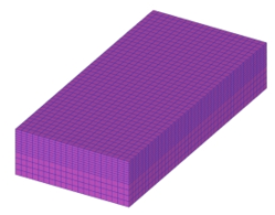
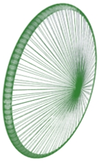
A mesh convergence study is performed to verify the mesh independence of the finite-element results. Three mesh densities are considered: a coarse mesh with an element size of approximately 2.0 mm in the contact zone (5348 elements), a medium mesh with an element size of approximately 1.0 mm (24 975 elements), and a fine mesh with an element size of approximately 0.5 mm (67 126 elements). A local mesh refinement strategy is adopted, in which the finest elements are concentrated in the rolling contact zone swept by the roller, whereas progressively coarser elements are used in regions away from the deformation zone, thereby balancing computational accuracy and efficiency. Eight-node coupled temperature–displacement brick elements with reduced integration and hourglass control (C3D8RT) are employed throughout the calculations; these elements are well suited to the material, geometric, and contact nonlinearities involved in the rolling process. The results of the mesh convergence analysis are summarized in Table 5. The relative deviations of the evaluated metrics between the medium and fine meshes are both below 1 %, whereas those of the coarse mesh relative to the medium mesh reach 16.33 % and 9.89 %, respectively. The medium mesh is therefore adopted for all rolling simulations reported in this paper. In addition, the arbitrary Lagrangian–Eulerian (ALE) adaptive meshing technique is applied to prevent excessive element distortion during large-deformation rolling, further ensuring the reliability of the numerical results.

For the residual-stress simulations, the mesh was, likewise, locally refined according to the severity of deformation. In the machined surface region, where severe plastic deformation and steep residual-stress gradients occur, the element size was refined to 0.50 mm; in the unmachined substrate region, which lies far from the strengthening-affected zone and exhibits only mild stress gradients, a coarser element size of 2.0 mm was used, with a smooth size transition between the two regions to preserve mesh quality. The convergence of the mesh is examined using five element sizes (1.00, 0.75, 0.50, 0.25, and 0.10 mm), with the maximum residual compressive stress and the depth of the strengthened layer serving as the convergence indicators. Refining the mesh from 0.50 to 0.10 mm changed both indicators by less than 2 %, indicating that a mesh-independent solution had essentially been achieved at 0.50 mm, whereas further refinement would substantially increase the computation time owing to the rapid growth in the element count. Conversely, element sizes larger than 0.50 mm produced noticeable changes in the predicted residual stress, failing to satisfy the convergence criterion. Accordingly, 0.50 mm was ultimately selected as the element size for the machined surface region in all subsequent simulations.
As the rollers are modeled as rigid bodies, they require neither meshing nor the assignment of material properties. The workpiece is discretized with hexahedral elements. To balance simulation accuracy against computational cost, local mesh refinement combined with absolute mesh control is applied: the machined region on the upper surface of the workpiece is locally refined, whereas the unmachined region at the bottom is meshed relatively coarsely. The downward motion and feed of the roller are imposed through prescribed translational paths, while all other degrees of freedom are constrained. Time-dependent functions are defined to specify the motion parameters, thereby establishing the boundary conditions of the roller.
The selection of an appropriate time increment is critical: an excessively large increment may cause severe mesh distortion and convergence difficulties, whereas an excessively small one substantially increases the computation time. For regions requiring high local accuracy, the time increment should be sufficiently small that the distance traveled by the roller in a single increment is less than of the characteristic element size. In the present simulation, the time increment is set to 0.0001 s, and the total number of increments is determined according to the simulation duration. To limit the storage requirements of the output files without compromising subsequent post-processing, results are saved every 50 increments. The fidelity of the dynamic simulation of the machining process is governed by the constitutive model of the material, which must therefore be selected with care. Constitutive models for a wide range of workpiece materials have been established through experimental, analytical, and numerical studies. Heat-assisted surface rolling shares the same fundamental strengthening mechanism as conventional cold plastic rolling. Moreover, the Johnson–Cook model accommodates a broad range of strain rates while accounting for strain hardening; strain rate hardening; and thermal softening, including the material softening induced by adiabatic heating generated during plastic deformation. This model is therefore adopted to define the plasticity parameters of the workpiece material (Wuertemberger and Palazotto, 2016; Zhang et al., 2020; Wang et al., 2021). The flow stress of the material is expressed by the following constitutive equation:
where A is the yield stress coefficient, B is the strain-hardening coefficient, n is the strain-hardening exponent, C is the strain rate coefficient, m is the thermal-softening exponent, ε is the equivalent plastic strain, ε* is the normalized effective plastic strain rate, and T* is the corresponding temperature. Among these,
where T is the current temperature, Troom is the room temperature, and Tmelt is the melting temperature.
Roll forming is a cold-plastic-deformation process, and the effect of temperature during the process can be neglected. The simplified form of this model is shown below (Zhong et al., 2022). The constitutive parameters used in the simulations are summarized in Table 6.
Table 6Johnson–Cook constitutive parameters of 30CrMoA medium-carbon low-alloy structural steel.
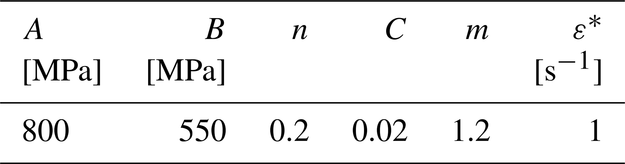
The specimens were prepared from 30CrMoA steel subjected to the same heat treatment as the components analyzed in the simulation. This treatment produces a tempered-sorbite microstructure, and the measured hardness and tensile strength of the steel meet the requirements for quenched and tempered 30CrMoA. The flow stress is described by a simplified Johnson–Cook model, with the thermal-softening term omitted because the process is essentially isothermal: the estimated temperature rise is small, corresponding to a very low homologous temperature, and therefore has a negligible effect on the flow stress (Hong et al., 2020). We select a sparse matrix solver and use the Newton–Larsen method for the iterative procedure.
3.1 Typical characteristics of residual-stress distribution
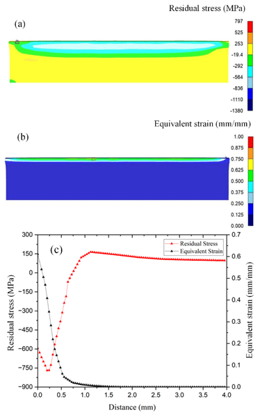
The stress field exhibits a typical layered distribution, characterized by moderate compressive stress in the surface layer, a peak compressive stress in the subsurface layer, a gradually decaying stress gradient in the transition zone, and near-zero stress in the base material (Zhou et al., 2023). This pattern is consistent with the formation mechanism of residual stresses induced by elastoplastic contact deformation. As shown in Fig. 5, the strengthening effect of mechanical rolling is confined to the near-surface region of the workpiece. Under concentrated contact loading, the von Mises stress peaks beneath the surface, as in a typical Hertzian field; yielding is therefore initiated in the subsurface, and the maximum plastic strain likewise lies below the surface. On unloading, the plastically deformed zone, constrained by the surrounding elastic material, cannot fully recover and therefore develops a self-equilibrating residual-stress field (the eigenstrain mechanism): the larger the magnitude and gradient of the plastic strain, the stronger the surrounding constraint and the higher the compressive residual stress. The surface compressive stress falls slightly below the subsurface peak because (i) the traction-free condition of the free surface partially relaxes the near-surface plastic strain, weakening the constraint, and (ii) work hardening raises the flow strength of the near-surface material. Outside the plastic zone, the material deforms purely elastically and recovers fully on unloading, and so the compressive residual stress decays rapidly to the base material level near the plastic zone boundary. The inflection point of the measured residual-stress profile coincides closely with the finite-element (FE)-predicted plastic zone boundary, further corroborating the reliability of the FE simulation.
The compressive stress in the near-surface region is slightly lower than the peak value in the subsurface layer. The surface acts as a free boundary with no material constraint on the outer side; moreover, during rolling, the near-surface material undergoes intense plastic flow, and part of the internal stress is relaxed through dislocation slip and grain rotation. Consequently, the compressive stress at the surface does not reach its maximum. At a certain depth below the surface, a continuous band of high-amplitude compressive stress forms. At this depth, the material undergoes the greatest plastic deformation while being strongly constrained by the surrounding elastic material; during unloading, the surrounding elastic material tends to recover its deformation but is impeded by the plastically deformed subsurface layer so that a peak in residual compressive stress forms. This region constitutes the core strengthening layer, which suppresses the steady-state propagation of fatigue cracks and effectively reduces the stress intensity factor at the crack tip. With further increases in depth, the residual compressive stress decreases approximately monotonically; beyond a certain depth it vanishes completely, and the stress deep in the interior approaches zero, remaining essentially unaffected by rolling. This distribution conforms to the principle of mechanical self-equilibrium: the residual compressive stress introduced in the surface layer is balanced by weak tensile stress in the interior. Since the thickness of the strengthened layer is much smaller than the overall dimensions of the workpiece, the magnitude of this balancing tensile stress is extremely low and does not adversely affect the overall mechanical properties of the material.
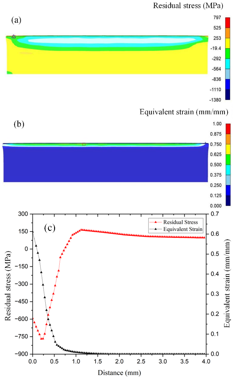
Figure 5Contour plot of residual-stress distribution across a cross-section under standard process parameters. (a) Residual stress. (b) Equivalent strain. (c) Variation curve.
The typical distribution characteristics described above confirm that mechanical rolling can introduce a residual compressive-stress field of high magnitude and substantial depth into the surface layer of the journal, with the peak compressive stress located in the subsurface layer. This region precisely coincides with the primary zone of steady-state crack propagation following fatigue crack initiation. The induced residual compressive-stress field is therefore expected to be beneficial for the fatigue performance of the workpiece; however, no direct fatigue testing was conducted in the present study. At the same time, the uniform distribution of axial stress ensures consistency in the strengthening effect across the entire length of the journal, providing a stress foundation for the long-term operational reliability of the gear. This typical distribution also serves as a reference for subsequent analyses of the influence of process parameters and for parametric modeling.
3.2 Effect of individual process parameters on residual stress
To isolate the individual effect of each process parameter, single-factor experiments are conducted using the controlled-variable method, in which the remaining parameters are held constant at their intermediate reference values. Three key parameters, rolling depth, feed rate, and workpiece rotational speed, are examined in terms of two evaluation metrics, namely the surface residual compressive stress and the compressive-stress layer depth, thereby identifying the effective range of each parameter and the associated plastic saturation effect.
3.2.1 Analysis of the effects of rolling depth
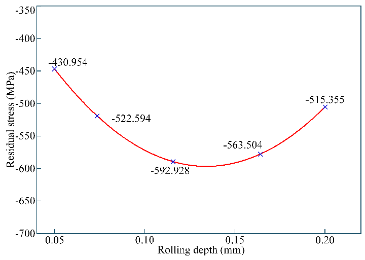
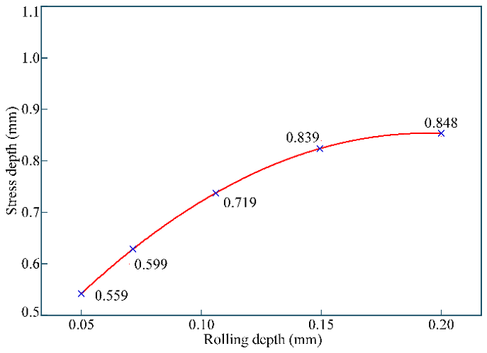
With the workpiece rotational speed held at 600 r min−1 and the feed rate at 0.05 mm r−1, five rolling depths (0.05, 0.07, 0.10, 0.15, and 0.20 mm) are selected to examine the influence of rolling depth on the residual-stress field. The through-depth distributions of residual stress for the five rolling depths, together with the relationships of rolling depth to the surface residual stress and the compressive-stress layer depth, are presented in Figs. 6–8, respectively.
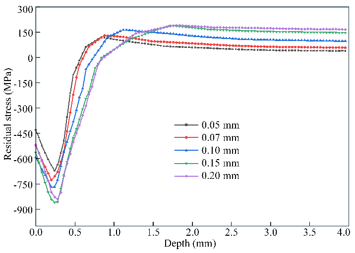
As shown in Fig. 6, the residual-stress distributions exhibit a consistent pattern across all rolling depths: the residual compressive stress at the outermost surface is moderate; as the depth increases, its magnitude rises continuously, reaching a peak in the subsurface layer at a depth of 0.2–0.4 mm; beyond the peak, the compressive stress decays gradually, approaching zero at approximately 0.8 mm; and at depths greater than about 1.5 mm, the stress becomes tensile, stabilizing at 100–180 MPa so as to equilibrate the compressive-stress field induced by plastic deformation in the surface layer. With increasing rolling depth, the entire stress profile shifts towards more negative values, the peak subsurface compressive stress increases in magnitude, and the compressive-stress layer deepens continuously, indicating that a greater rolling depth effectively increases the extent of plastic deformation in the surface layer.
As shown in Fig. 7, at a rolling depth of 0.05 mm, the surface residual compressive stress is only −430.96 MPa. In this case, the shallow radial penetration of the roller results in insufficient plastic flow of the surface metal, limited dislocation multiplication and grain refinement, and a weak constraint effect upon unloading and springback, yielding only a low-magnitude residual compressive stress. As the rolling depth increases from 0.05 to 0.10 mm, the surface residual compressive stress rises continuously, reaching a maximum of −592.93 MPa at 0.10 mm. At this stage, the increased rolling depth directly enlarges the contact pressure and contact area between the roller and the workpiece; extensive irreversible plastic slip occurs in the surface metal; the degree of lattice distortion increases markedly; and the constraining effect of the subsurface elastic material on the deformed layer is progressively strengthened, macroscopically manifested as a continuous increase in the magnitude of the surface residual compressive stress. When the rolling depth exceeds 0.10 mm, the magnitude of the surface residual compressive stress declines slightly, measuring −563.60 MPa at 0.15 mm and −515.36 MPa at 0.20 mm. When the rolling depth is excessive, severe plastic flow occurs in the surface metal, leading to localized tearing and metal bulging in the surface microstructure. The stress relaxation induced by such excessive surface plastic deformation partially offsets the gain in residual compressive stress. Moreover, the increased through-thickness gradient of plastic strain within the strengthened layer induces a slight redistribution of the self-equilibrating stress field between the work-hardened layer and the underlying base material, which further reduces the magnitude of the retained compressive stress.
As shown by the compressive-stress-layer depth curve in Fig. 8, the strengthened layer depth increases rapidly at first and then grows more slowly and eventually approaches saturation as the rolling depth increases. At a rolling depth of 0.05 mm, the compressive-stress layer depth is only 0.5594 mm; within the range of 0.05–0.15 mm, it increases approximately linearly, reaching 0.8591 mm at 0.15 mm; when the rolling depth is further increased to 0.20 mm, the layer depth rises only marginally to 0.8764 mm, an increment of less than 0.02 mm, indicating that the plastic deformation has reached saturation. Owing to the strong constraint of the deep base material, the rolling load cannot be effectively transmitted further into the bulk; consequently, further increasing the radial indentation depth cannot continuously extend the influence zone of the residual compressive stress.
3.2.2 Analysis of the effect of workpiece rotational speed
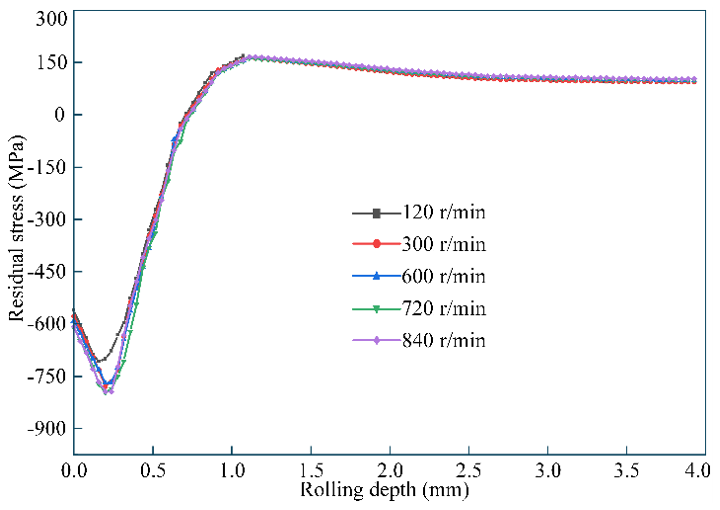
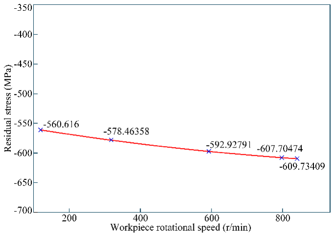
With the rolling depth fixed at 0.10 mm and the feed rate at 0.05 mm r−1, single-factor experiments are performed at five workpiece rotational speeds (120, 360, 600, 720, and 840 mm r−1) to investigate the influence of rotational speed on the residual stress distribution, the surface stress magnitude, and the compressive-stress layer depth. The corresponding results are presented in Figs. 9–11. As shown by the through-depth residual stress distributions in Fig. 9, the overall distribution profile remains essentially consistent across the different rotational speeds, with a distinct compressive-stress peak in the subsurface layer. With increasing rotational speed, however, the entire stress profile shifts progressively towards more negative values, and the magnitude of the peak compressive stress increases accordingly.
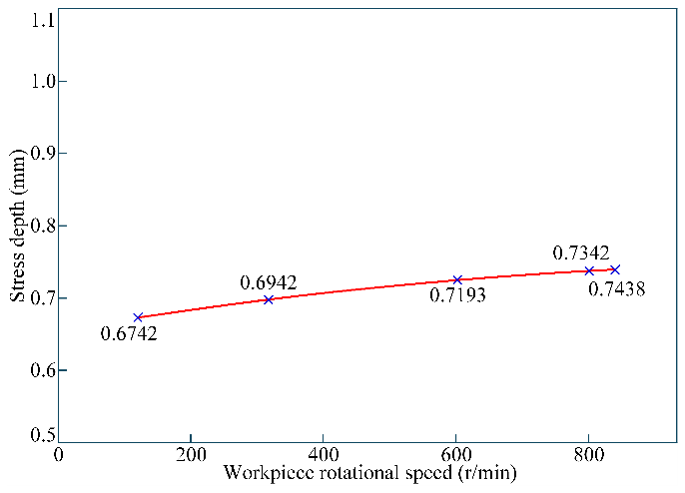
At lower rotational speeds, the roller dwells longer at each circumferential position, producing a steeper localized spatial gradient of plastic strain. This steep gradient in turn promotes cyclic plasticity and elastic shakedown of the surface layer under repeated rolling passes, thereby relaxing part of the induced residual compressive stress. As the rotational speed increases, the contact duration is shortened, and the spatial gradient of plastic strain is markedly reduced so that the residual compressive stress induced by plastic deformation is more fully retained (Zhao and Zhao, 2026). In the low-speed range, the rotational speed exerts a relatively minor influence on the surface stress, with a variation of less than 20 MPa; in the medium-to-high-speed range, the magnitude of the surface compressive stress increases markedly as the elevated rotational speed increasingly suppresses cyclic plasticity under repeated rolling passes. When the rotational speed exceeds 720 r min−1, however, the relative sliding speed between the workpiece and the roller becomes excessive, intensifying localized micro-slip and causing slight frictional damage to the surface layer, which leads to a marginal decay of the residual compressive stress. As shown in Fig. 10, at a workpiece rotational speed of 120 r min−1, the surface residual compressive stress is only −560.62 MPa; it rises slightly to −578.46 MPa at 360 r min−1 and reaches its maximum of −609.73 MPa at 720 r min−1; a further increase to 840 r min−1 results in a slight decrease to −607.70 MPa. At low rotational speeds, the residual compressive stress generated by plastic deformation in the subsurface layer undergoes relaxation, reducing the thickness of the effective strengthened layer. A moderate increase in rotational speed alleviates the local temperature rise, allows the rolling load to be transmitted more fully into the subsurface layer, and broadens the plastic-deformation zone. At excessively high rotational speeds, however, the roller–workpiece contact time becomes insufficient for the plastic deformation to fully develop within a single pass so that the strengthened layer thickness decreases slightly.
As shown in Fig. 11, the compressive-stress layer depth is only 0.67417 mm at 120 r min−1; it then increases monotonically with rotational speed, reaching a maximum of 0.74384 mm at 720 r min−1 before decreasing slightly to 0.73417 mm at 840 r min−1. Comparing the changes induced by rolling depth and by workpiece rotational speed reveals that the latter has a weaker influence on the residual stress than the former because rotational speed regulates plastic deformation only indirectly, through the contact duration and the process-induced temperature rise. Considering both the strengthening effectiveness and the processing stability, the optimal workpiece rotational speed range is 600–720 r min−1, within which a high surface residual compressive stress and a deep strengthened layer can be achieved.
3.2.3 Analysis of the effects of feed rate
With the rolling depth fixed at 0.10 mm and the workpiece rotational speed at 360 r min−1, single-factor experiments are performed at five feed rates (0.01, 0.03, 0.05, 0.07, and 0.10 mm r−1) to investigate the influence of the axial feed rate on the residual-stress field. The resulting through-depth residual-stress distributions, together with the variations in the surface residual stress and the compressive-stress layer depth, are presented in Figs. 12–14, respectively.
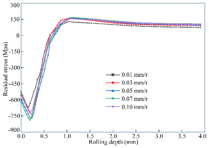
As shown in Fig. 12, the feed rate directly determines the overlap ratio of adjacent axial rolling tracks, thereby governing the extent of plastic deformation accumulated in the surface layer. At lower feed rates, the overlap between adjacent tracks increases so that each surface location is rolled repeatedly, which promotes sufficient accumulation of plastic deformation and shifts the stress profile further towards negative values. As the feed rate increases, the degree of track overlap diminishes; the number of rolling passes over a given local region becomes insufficient, the extent of plastic deformation is reduced, and both the peak compressive stress and the surface compressive stress decrease accordingly. At low feed rates, however, the roller repeatedly passes over the same region, causing continuous accumulation of process heat in the surface layer; the resulting cyclic plasticity under repeated rolling passes then partially relaxes the residual compressive stress, leading to a lower compressive-stress magnitude. At feed rates of 0.05–0.07 mm r−1, the track overlap is moderate, the process temperature rise remains controllable, and the accumulation of plastic deformation is optimal so that the surface residual compressive stress reaches its maximum.
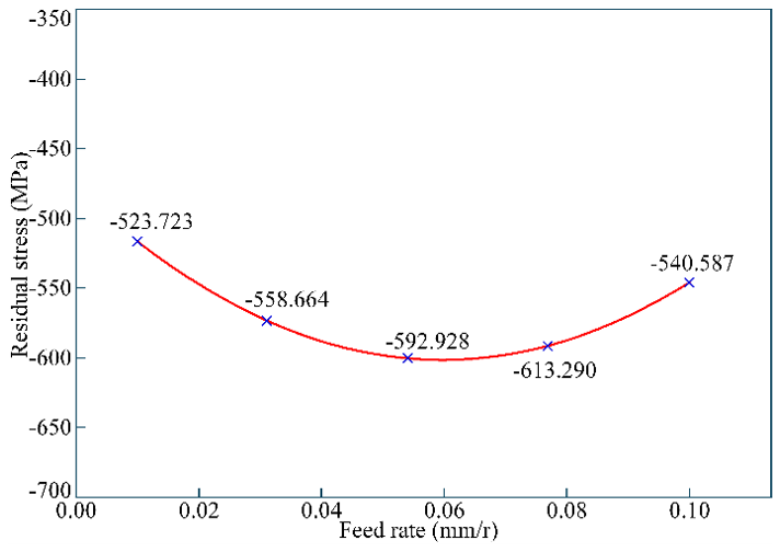
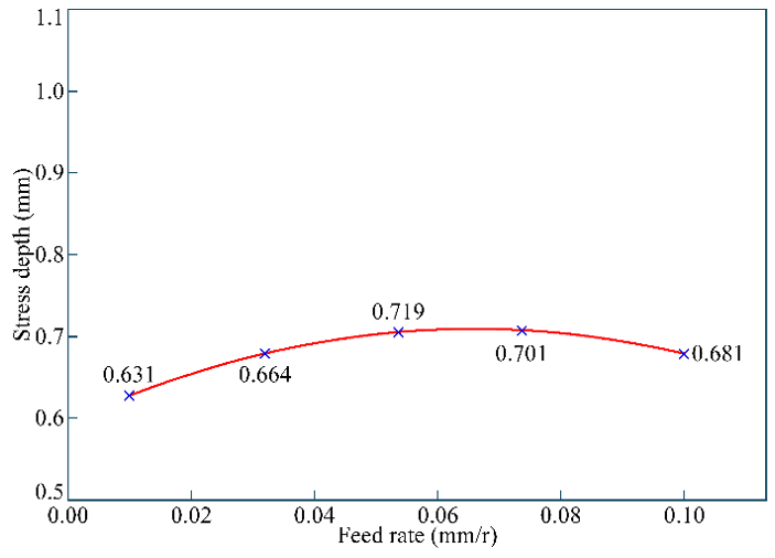
When the feed rate exceeds 0.07 mm r−1, pronounced gaps emerge between adjacent axial rolling tracks; some regions experience only a single rolling pass or are not fully compressed, resulting in insufficient plastic deformation and a marked decay of the surface residual compressive stress. A quantitative analysis of the surface residual stress variation is presented in Fig. 13. At a feed rate of 0.01 mm r−1, the surface residual compressive stress is only −523.72 MPa; as the feed rate increases from 0.01 to 0.07 mm r−1, its magnitude rises continuously, reaching a maximum of −613.29 MPa at 0.07 mm r−1; beyond 0.07 mm r−1, the surface compressive stress decreases rapidly in magnitude, falling to −540.59 MPa at 0.10 mm r−1. At extremely low feed rates, the temperature rise induced by repeated rolling weakens the subsurface compressive stress, limiting the thickness of the strengthened layer. At moderate feed rates, plastic deformation accumulates uniformly, and the rolling load is transmitted fully into the bulk material, yielding the maximum compressive-stress layer depth. At high feed rates, the axial rolling coverage becomes non-uniform, and plastic deformation is confined to an extremely thin surface layer, significantly reducing the compressive-stress layer depth. As shown in Fig. 14, the compressive-stress layer depth is only 0.63091 mm at a feed rate of 0.01 mm r−1; it increases to a peak of 0.71923 mm at 0.05 mm r−1 and then decreases gradually to 0.68035 mm as the feed rate rises to 0.10 mm r−1. Considering both the surface residual-stress magnitude and the compressive-stress layer depth, the optimal feed rate range is 0.05–0.07 mm r−1: an excessively low feed rate prolongs the processing time and intensifies the cyclic plasticity induced by repeated rolling passes, whereas an excessively high feed rate causes non-uniform axial hardening and substantially reduces the overall residual compressive-stress level.
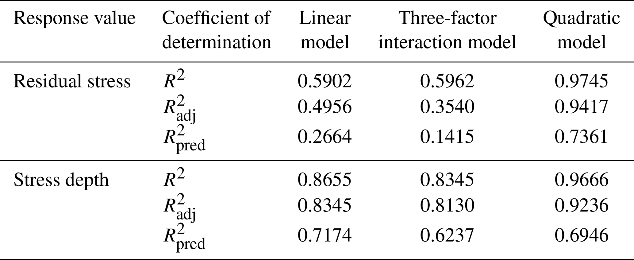
Table 10Analysis of variance for response surface regression models.
3.2.4 Comprehensive comparison of individual process parameters and summary of patterns
A comparison of the maximum variations in the surface residual stress and the compressive-stress layer depth across the three single-factor experiments indicates that the influence of the three process parameters on the residual-stress field decreases in the following order: rolling depth > feed rate > workpiece rotational speed. The single-factor experiments quantify the individual influence of each parameter and identify the corresponding processing thresholds, thereby avoiding two types of undesirable processing scenarios: first, insufficient parameter levels, which lead to inadequate plastic deformation and a low level of residual compressive stress, and, second, excessive parameter levels, which induce surface over-extrusion, excessive cyclic plasticity under repeated rolling passes, and non-uniform rolling, all of which weaken the strengthening effect on the gear journal. Moreover, the parameter ranges identified here provide a rational basis for the subsequent response surface methodology based on the central composite design (CCD), which is used to develop multi-factor coupling and predictive models for residual stress, effectively narrowing the sample space of the multi-factor experiments and improving the fitting accuracy of the resulting parametric models.
3.3 Effect of individual process parameters on residual stress
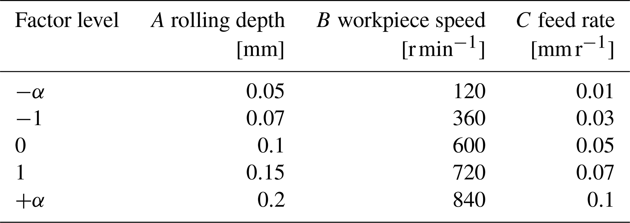
The rolling depth, feed rate, and workpiece rotational speed are taken as the input factors, each at five levels. Based on the single-factor experimental results, the effective ranges of the three parameters are determined as 0.05–0.20 mm for the rolling depth, 0.01–0.10 mm r−1 for the feed rate, and 120–840 r min−1 for the workpiece rotational speed. The corresponding coded levels are listed in Table 7. The surface residual compressive stress and the compressive-stress layer depth are taken as the response variables.
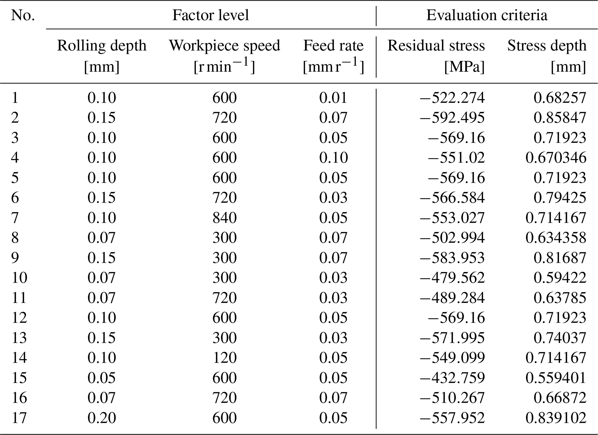
A CCD is employed in this study, comprising 14 factorial runs and 3 center-point replicates. A finite-element model is established for each parameter combination to perform the corresponding numerical simulations. The factor settings and corresponding response values for each experimental run are listed in Table 8.
Based on the data in Table 8, regression models are developed to relate the two responses, the surface residual compressive stress and the compressive-stress layer depth, to the rolling depth, feed rate, and workpiece rotational speed. Three candidate models are considered: a linear model, a two-factor-interaction (2FI) model, and a quadratic model. The fitting accuracy of the three models is evaluated, and the results are summarized in Table 9.
A comparison of the model statistics in Table 9 indicates that the quadratic model provides the best fit; it is therefore adopted for the regression analysis of the experimental data, yielding a mathematical model relating each response variable to the coded values of the process parameters. The general form of the model is expressed as follows:
where Y represents the response, β0 is the constant term, βi is the coefficient of the linear term, βii is the coefficient of the quadratic term, βij is the coefficient of the interaction term, and ε is the random error. The coefficients of each term were estimated using the least-squares method, and insignificant terms were eliminated through stepwise regression, ultimately yielding the simplified regression equations for each response.
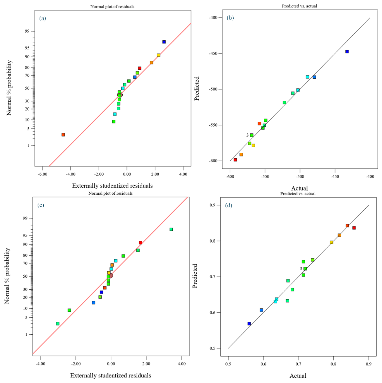
Figure 15Residual analysis and actual-versus-predicted comparisons: (a) residual analysis (residual stress), (b) actual versus predicted values (residual stress), (c) residual analysis (depth of the strengthened layer), and (d) actual versus predicted values (depth of the strengthened layer).
From the regression coefficients, the absolute value of the linear coefficient A is the largest, indicating that the rolling depth exerts the dominant influence on the response values. The interaction terms AB and AC are significant, demonstrating pronounced coupling effects between the rolling depth and the feed rate (AB), as well as between the rolling depth and the workpiece rotational speed (AC). The significance of the quadratic terms indicates that the responses exhibit nonlinear behavior with varying process parameters, which is consistent with the plastic saturation pattern observed in the single-factor experiments.
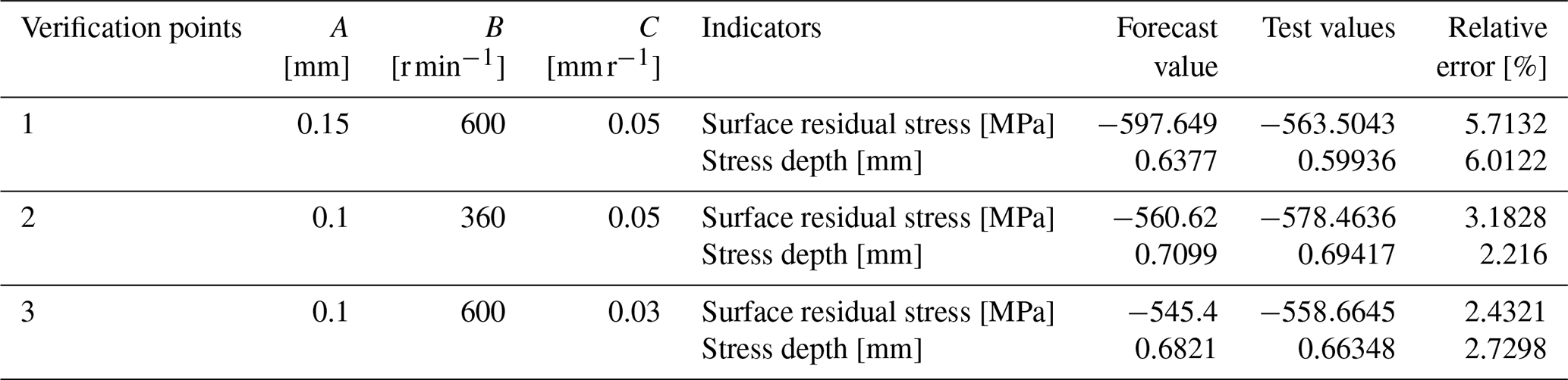
Table 12Candidate solutions and overall expected value in multi-objective optimization.
A complete set of statistical metrics – R2, adjusted R2, and predicted R2 – has now been provided for the two response variables (residual stress and depth of the strengthened layer). In addition, residual diagnostic plots, including a normal probability plot of the residuals and a plot of residuals versus fitted values, are provided in the Supplement, as shown in Fig. 15. The goodness of fit of a regression model is commonly assessed using three metrics: the coefficient of determination (R2), adjusted R2, and predicted R2. R2 and adjusted R2 generally range from 0 to 1; the closer these values are to 1 and the smaller the discrepancy between the adjusted R2 and the predicted R2, the better the regression model fits the experimental data.
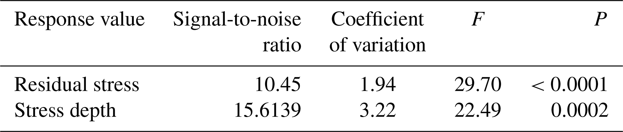
Analysis of variance (ANOVA) is performed on the two regression models, and the results are summarized in Table 10. As shown in the table, the F values of the models are 29.70 and 22.49, respectively, with corresponding p values all below 0.01, indicating that the regression models are highly significant and that the differences among the process parameters are statistically significant. The coefficients of variation are all below 5 %, well within the 10 % acceptance criterion, indicating good data stability. Moreover, the signal-to-noise ratios are all well above 4, confirming that the models possess adequate precision. These results demonstrate that the models are statistically reliable.
To comprehensively evaluate the predictive reliability of the parametric model under practical operating conditions, three sets of process parameter combinations are randomly selected within the CCD design space, distinct from those used in the regression modeling, and are employed in supplementary validation experiments. The relative errors between the predicted and measured values are calculated, and the validation results are presented in Table 11.
The results show that the maximum relative error between the predicted and experimentally measured surface residual compressive stresses is 5.71 %, while that of the compressive-stress layer depth is 6.01 %. Both errors are well below 10 %, satisfying the prediction accuracy requirement and confirming that the established parametric models can reliably predict the residual stress characteristics of 30CrMoA gear journals under various rolling-process conditions.
3.4 Multi-objective process optimization and experimental validation
To improve the surface integrity of journal surfaces by rolling, a multi-objective optimization is performed on the basis of the response surface models developed above, following the methodology of He et al. (2025), to determine the optimal combination of process parameters; the reliability of the optimization results is subsequently verified through confirmation experiments. Taking the maximization of the surface residual compressive stress and the compressive-stress layer depth as the objectives, the desirability function approach (DFA) is employed to obtain the optimal process parameter combination.
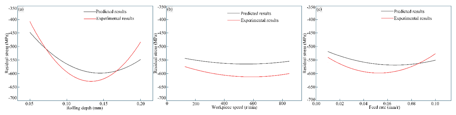
Figure 16Comparison chart of surface residual stress prediction experiments. (a) Rolling depth. (b) Workpiece speed. (c) Feed rate.
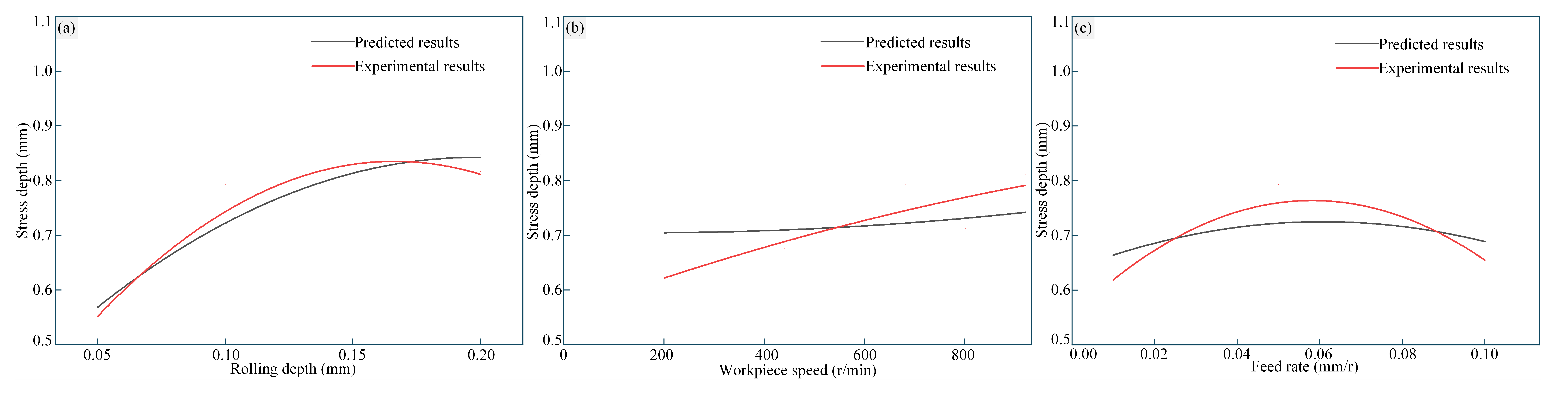
Figure 17Comparison chart of stress layer depth prediction experiments. (a) Rolling depth. (b) Workpiece speed. (c) Feed rate.
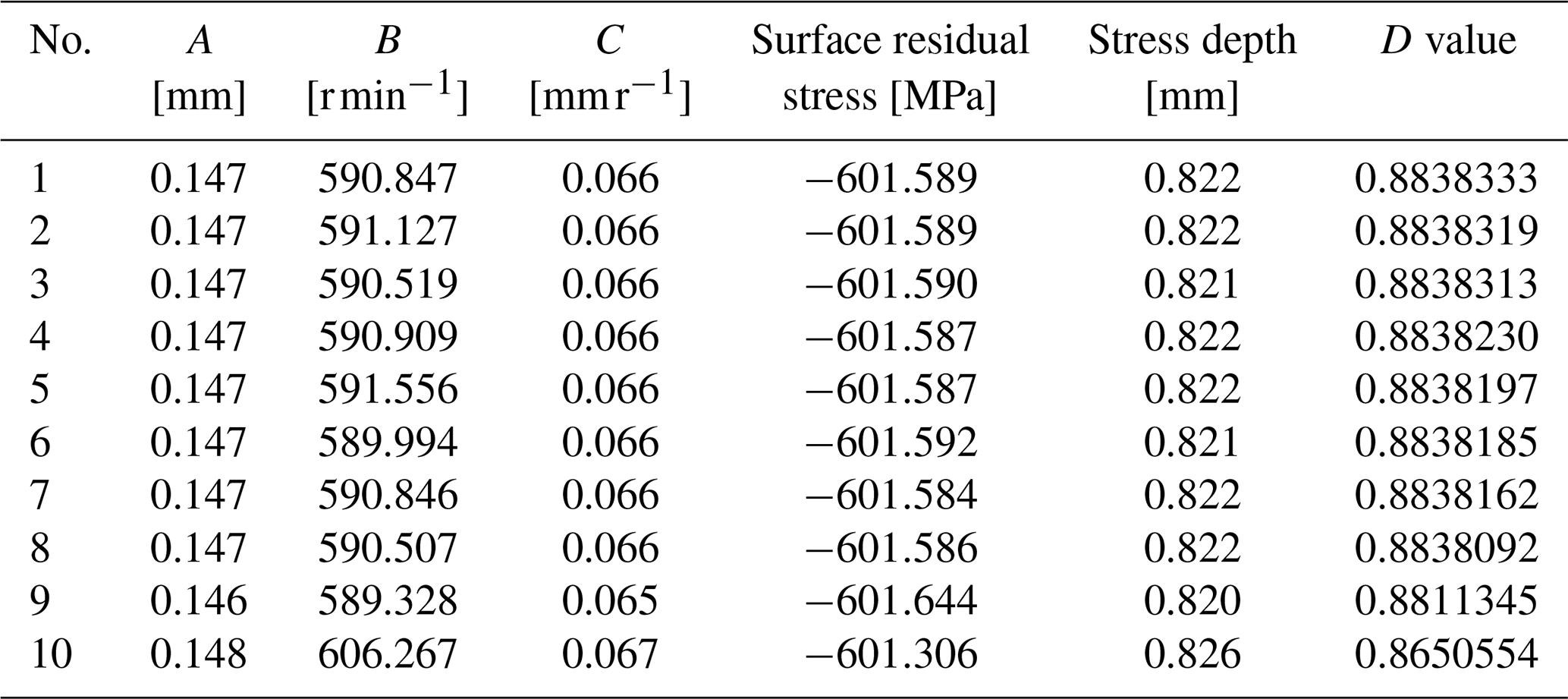
Using the built-in optimization module of Design-Expert software, the overall desirability value D is calculated for each candidate combination, and the ten solutions with the highest D values are selected. To avoid the arbitrariness associated with relying on a single optimal solution, the feasibility of the process parameters and the capabilities of the equipment are comprehensively considered. The final optimal combination of process parameters is presented in Table 12.
Based on the composite desirability (D) and process feasibility, group 1 is selected as the optimal process condition: a rolling depth of 0.147 mm, a feed rate of 0.066 mm r−1, and a workpiece rotational speed of 590 r min−1. Under this parameter combination, the model predicts a surface residual compressive stress of −601.59 MPa and a compressive-stress layer depth of 0.822 mm. All individual objectives satisfy the constraint requirements, and the overall desirability reaches 0.884.
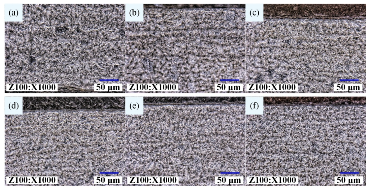
Figure 18Internal microstructure under different rolling-process parameters: (a) initial state, (b) 0.05 mm, (c) 0.1 mm, (d) 0.15 mm, (e) 0.2 mm, (f) 0.147 mm–590 r min−1–0.06 mm r−1.
To verify the reliability of the multi-objective optimization results under practical operating conditions, experiments are conducted using the optimal process parameters, and the measured data are compared with the model predictions. The comparison between the predicted and experimental results is presented in Figs. 16 and 17. The predicted results are in excellent agreement with the experimental measurements across all investigated process parameters. For the three single-factor experimental sets, namely rolling depth, workpiece rotational speed, and feed rate, the mean relative deviations in predicted surface residual stress are 6.42 %, 7.67 %, and 6.06 %, respectively, while those for compressive-stress layer depth are 4.33 %, 7.57 %, and 4.94 %, respectively. Since all relative deviations remain below 8.0 %, the model demonstrates satisfactory predictive accuracy for both surface residual stress and compressive-stress layer depth. Moreover, the simulation results faithfully reproduce the evolution trends of residual stress with varying process parameters, showing good consistency with the experimental observations. To comprehensively evaluate the overall improvement in journal surface integrity achieved through process optimization and to further elucidate the microstructural evolution at different depths below the surface under the optimal process parameters, the corresponding results are presented in Fig. 18. The mechanistic interpretation is grounded in mutually corroborating indirect evidence, including the measured microhardness gradient, the residual stress distribution, and the plastic flow features observed experimentally. Given the well-established correlation among process parameters, plastic flow, work hardening, and microstructure evolution under severe plastic-deformation conditions (Ni et al., 2025), this interpretation rests on a sound methodological basis.
As the rolling depth increases, the surface grains undergo significant plastic flow along the rolling direction. At a rolling depth of 0.05 mm, the surface grains are slightly elongated, the deformation layer remains thin, and the grain boundaries are still clearly discernible. When the rolling depth increases to 0.10 mm, the grain deformation intensifies: the original equiaxed grains transform into a fibrous microstructure, accompanied by a pronounced increase in the deformation layer thickness. Upon further increasing the rolling depth to 0.15 mm, the surface grains become markedly flattened and elongated, the flow line structure becomes increasingly dense, and some grain boundaries are disrupted, giving rise to numerous subgrains and dislocation cells. At a rolling depth of 0.20 mm, the deformation layer continues to thicken; however, noticeable plastic pile-up and micro-wrinkling emerge on the surface. Although grain refinement is further enhanced, the deformation uniformity deteriorates somewhat.
Figure 18f presents the surface microstructure obtained under the optimal combination of process parameters. It can be observed that the grains are finer and that the deformation is more uniform under these conditions, while the deformation layer is also thicker; both the degree of grain refinement and the deformation uniformity are superior to those of the single-factor experimental groups. Compared with Fig. 18d, the deformation layer of the optimal group is denser and more uniform, with no evident localized accumulation or non-uniform deformation. This indicates that, under the synergistic action of a relatively large rolling depth, a moderate rotational speed, and a moderate feed rate, the surface layer of the material undergoes sufficient and uniform plastic deformation, thereby producing the most favorable grain refinement.
-
Mechanical rolling induces a stable residual compressive-stress field with a characteristic gradient distribution in the surface layer of the 30CrMoA gear journal. The peak residual compressive stress lies approximately 0.20 mm beneath the surface, reaching a magnitude of over 800 MPa. The compressive stress in the surface layer ranges from 400 to 600 MPa, slightly below the peak value, whereas the deeper base material exhibits a weak balancing tensile stress of approximately 100–180 MPa. This stress configuration provides an effective barrier against fatigue crack initiation and steady-state propagation.
-
Single-factor experiments reveal that the influence of the three process parameters on the residual-stress field decreases in the following order: rolling depth > feed rate > workpiece rotational speed. Increasing the rolling depth significantly enhances both the compressive-stress magnitude and the compressive-stress layer depth; however, once the rolling depth exceeds 0.10 mm, plastic saturation sets in, and repeated rolling passes intensify the cyclic plasticity in the surface layer, resulting in a slight decline in the stress magnitude. The workpiece rotational speed and feed rate exhibit optimal ranges of 600–720 r min−1 and 0.05–0.07 mm r−1, respectively; values outside these ranges weaken the strengthening effect owing to the excessive spatial gradient of plastic strain or non-uniform rolling coverage.
-
The quadratic regression models for the residual stress and the compressive-stress layer depth, established using the response surface methodology based on the central composite design (CCD), are demonstrated by analysis of variance to be highly significant (p<0.01), with signal-to-noise ratios greater than 4 and coefficients of variation below 5 %. Validation tests show that the maximum relative errors in predicting the surface residual stress and the compressive-stress layer depth are 5.71 % and 6.01 %, respectively, both well below 10 %, confirming that the parametric models can accurately predict the residual-stress characteristics under various rolling conditions.
-
The optimal combination of process parameters determined through multi-objective optimization consists of a rolling depth of 0.147 mm, a feed rate of 0.066 mm r−1, and a workpiece rotational speed of 590 r min−1. Under these conditions, the model predicts a surface residual compressive stress of −601.59 MPa and a compressive-stress layer depth of 0.822 mm. Microstructural observations reveal that the surface layer undergoes uniform grain refinement and develops a dense deformation layer under the optimal process parameters, achieving a well-balanced combination of a high surface compressive stress and a deep strengthened layer, thus validating the reliability and effectiveness of the optimization results.
All relevant data are provided within the paper.
Conceptualization: XW and XZ. Methodology: XW and XX. Software: XX. Validation: XW, XZ and XX. Formal analysis: XX. Investigation: XW and XX. Resources: XW. Data curation: XX. Writing (original draft preparation): XW and XX. Writing (review and editing): XW, XZ, and XX. Visualization: XW and XX. Supervision: XW and XX. Project administration: XW and XX. All of the authors have read and agreed to the published version of the paper.
The contact author has declared that none of the authors has any competing interests.
Publisher's note: Copernicus Publications remains neutral with regard to jurisdictional claims made in the text, published maps, institutional affiliations, or any other geographical representation in this paper. The authors bear the ultimate responsibility for providing appropriate place names. Views expressed in the text are those of the authors and do not necessarily reflect the views of the publisher.
The authors would like to thank the Huaqiao University (HQU) and Xiamen University of Technology (XUT) for their support. The authors sincerely appreciate all of the participants for their contributions.
This research was funded by the National Natural Science Foundation Sponsored Project (project no. 52475257), the National Key Research and Development Program Project (grant no. 2023YFB3406301), the Fund Project for Technological Field of National Defense Science and Technology Plan 173 (grant nos. 2024-JCJQ-JJ-2020 and 2024-JCJQ-JJ-2043), and the Marine Propulsion Research and Development (MPRD) Program (grant no. MG20220203).
This paper was edited by Jeong Hoon Ko and reviewed by two anonymous referees.
Aliakbari, K., Nejad, R., Mamaghani, T., Pouryamout, P., and Asiabaraki, H.: Failure analysis of ductile iron crankshaft in compact pickup truck diesel engine, Structures, 36, 482–492, https://doi.org/10.1016/j.istruc.2021.12.034, 2022a.
Aliakbari, K., Nejad, R., Toroq, S., Macek, W., and Branco, R.: Assessment of unusual failure in crankshaft of heavy-duty truck engine, Engineering Failure Analysis, 134, 106085, https://doi.org/10.1016/j.engfailanal.2022.106085, 2022b.
Bialowas, J., Pletz, M., Gapp, S., and Maierhofer, J.: A method to reduce computation time in finite element simulations of deep rolling, Procedia Structural Integrity, 46, 49–55, https://doi.org/10.1016/j.prostr.2023.06.009, 2023.
Caddemi, S.: Computational aspects of the integration of the von Mises linear hardening constitutive laws, Int. J. Plasticity, 10, 935–956, https://doi.org/10.1016/0749-6419(94)90021-3, 1994.
Chen, Z. W., Wang, F., Zhang, H. B., Chen, Z. G., and He, Q. L.: Performance and safety evaluation of rack vehicle in mountainous regions under pulsating wind loads, Mech. Based Des. Struc., 54, 2553887, https://doi.org/10.1080/15397734.2025.2553887, 2025.
Dänekas, C., Heikebrügge, S., Schubnell, J., Schaumann, P., Breidenstein, B., and Bergmann, B.: Influence of deep rolling on surface layer condition and fatigue life of steel welded joints, Int. J. Fatigue, 162, 106994, https://doi.org/10.1016/j.ijfatigue.2022.106994, 2022.
Dos, S. F. F., Silva, S. D. C., Abrão, A. M., Denkena, B., Breidenstein, B., and Meyer, K.: Influence of the carbon content on the surface integrity of deep rolled steels, J. Tribol., 143, 081702, https://doi.org/10.1115/1.4049109, 2021.
Fonseca, L. G. A. and Faria, A. R. D.: A deep rolling finite element analysis procedure for automotive crankshafts, J. Strain Anal. Eng., 53, 178–188, https://doi.org/10.1177/0309324717751942, 2018.
Fonseca, L. G. A. and Faria, A. R. D.: Crankshaft deep rolling analysis through energy balance simulation output, J. Braz. Soc. Mech. Sci., 41, 430, https://doi.org/10.1007/s40430-019-1932-3, 2019.
Fu, J., Sun, S., Gong, X., Shen, S., Jiang, N., and Juan, J.: Research on the Accelerated Fatigue Experiment Method of the Crankshaft Based on a Modified Particle Filtering Algorithm and the Fatigue Crack Growth Property, Materials, 19, 481, https://doi.org/10.3390/ma19030481, 2026.
He, R., Dai, Y. H., Jin, J. J., Yan, J., and Liu, D.: The effects of time preferences on farmers' energy-saving and emission-reducing behavior of agricultural machinery in a gain-loss dual context: Evidence from rural China, Energy, 341, 139325, https://doi.org/10.1016/j.energy.2025.139325, 2025.
Heikebrügge, S., Breidenstein, B., Bergmann, B., Dänekas, C., Schaumann, P., and Schubnell, J.: Identification of material properties for finite element simulation of the deep rolling process applied to welded joints, Procedia CIRP, 115, 30–35, https://doi.org/10.1016/j.procir.2022.10.045, 2022a.
Heikebrügge, S., Breidenstein, B., Bergmann, B., Dänekas, C., and Schaumann, P.: Experimental and Numerical Investigations of the Deep Rolling Process to Analyze the Local Deformation Behavior of Welded Joints, Journal of Manufacturing and Materials Processing, 6, 50, https://doi.org/10.3390/jmmp6030050, 2022b.
Hong, Y., Wang, L. Z., Zhang, J. F., and Gao, Z. W.: 3D Elastoplastic Model for Fine-Grained Gassy Soil Considering the Gas-Dependent Yield Surface Shape and Stress-Dilatancy, J. Eng. Mech., 146, 04020037, https://doi.org/10.1061/(ASCE)EM.1943-7889.0001760, 2020.
Jalili, A. and Ashtiani, H. R.: Numerical analysis and neural-network modeling for predicting the thermo-viscoplastic behavior of Cu/AA2030 panel during the hot rolling process, Multiscale and Multidisciplinary Modeling, Experiments and Design, 9, 179, https://doi.org/10.1007/s41939-026-01262-2, 2026.
Kinner-Becker, T. and Sölter, J.: Influence of initial stress on the residual stress generated by deep rolling, Procedia CIRP, 117, 128–132, https://doi.org/10.1016/j.procir.2023.03.023, 2023.
Kinner-Becker, T., Sölter, J., and Karpuschewski, B.: A simulation-based analysis of internal material loads and material modifications in multi-step deep rolling, Procedia CIRP, 87, 515–520, https://doi.org/10.1016/j.procir.2020.02.060, 2020.
Kinner-Becker, T., Hettig, M., Sölter, J., and Meyer, D.: Analysis of internal material loads and Process Signature Components in deep rolling, CIRP Journal of Manufacturing Science and Technology, 35, 400–409, https://doi.org/10.1016/j.cirpj.2021.06.024, 2021.
Kluz, R., Antosz, K., Trzepieciński, T., and Bucior, M.: Modelling the influence of slide burnishing parameters on the surface roughness of shafts made of 42CrMo4 heat-treatable steel, Materials, 14, 1175, https://doi.org/10.3390/ma14051175, 2021.
Kumar, A., Rath, S., and Kumar, M.: Simulation of plate rolling process using finite element method, Mater. Today-Proc., 42, 650–659, https://doi.org/10.1016/j.matpr.2020.11.050, 2021.
Łach, Ł.: Recent Advances in Laser Surface Hardening: Techniques, Modeling Approaches, and Industrial Applications, Crystals, 14, 726, https://doi.org/10.3390/cryst14080726, 2024.
Li, X., Liang, G., Ling, X., Xu, C., and Xu, J.: An investigation of relationships between statistical dispersion of crankshaft's fatigue properties and initial damage, Eng. Fail. Anal., 154, 107680, https://doi.org/10.1016/j.engfailanal.2023.107680, 2023.
Luo, Y., Yue, G., Chen, B., Huang, B., Liu, F., Zhou, L., Mao, X., Deng, S., Du, J., and Liu, K.: Fatigue fracture analysis of the 42CrMo4 crankshaft used for mining dump truck, Eng. Fail. Anal., 154, 107724, https://doi.org/10.1016/j.engfailanal.2023.107724, 2023.
Ma, K., Du, J., Liu, Y., and Chen, Y.: Torsional vibration attenuation of a closed-loop engine crankshaft system via the tuned mass damper and nonlinear energy sink under multiple operating conditions, Mech. Syst. Signal Pr., 207, 110941, https://doi.org/10.1016/j.ymssp.2023.110941, 2024.
Martins, A. M., Oliveira, D. A. D., de Castro Magalhães, F., and Abrão, A. M.: Relationship between surface characteristics and the fatigue life of deep rolled AISI 4140 steel, Int. J. Adv. Manuf. Tech., 129, 1127–1143, https://doi.org/10.1007/s00170-023-12332-x, 2023.
Morrev, P. G. and Gordon, V. A.: Simulation of surface hardening in the deep rolling process by means of an axial symmetric nodal averaged finite element, Journal of Physics: Conference Series, vol. 973, International Conference “Applied Mathematics, Computational Science and Mechanics: Current Problems” 18–20 December 2017, Voronezh, Russian Federation, 973, 012013, https://doi.org/10.1088/1742-6596/973/1/012013, 2018.
Nguyen, T. T., Nguyen, T. A., Trinh, Q. H., Ba Le, X., Hai Pham, L., and Hung Le, L.: Artificial neural network-based optimization of operating parameters for minimum quantity lubrication-assisted burnishing process in terms of surface characteristics, Neural Comput. Appl., 34, 7005–7031, https://doi.org/10.1007/s00521-021-06834-6, 2022.
Ni, Z. L., Han, B. L., Nazarov, A. A., Yuan, Z. P., Li, N. N., Li, H., Sun, C. Y., and Yang, J. W.: Enhanced formation quality and mechanical properties of ultrasonic spot welding of TA2 Ti sheets by pure Al coating, J. Manuf. Process., 156, 1–16, https://doi.org/10.1016/j.jmapro.2025.10.084, 2025.
Noronha, D. J., Sharma, S., Prabhu Parkala, R., Shankar, G., Kumar, N., and Doddapaneni, S.: Deep Rolling Techniques: A Comprehensive Review of Process Parameters and Impacts on the Material Properties of Commercial Steels, Metals, 14, 667, https://doi.org/10.3390/met14060667, 2024.
Pertoll, T., Buzzi, C., Leitner, M., and Boronkai, L.: Numerical parameter sensitivity analysis of residual stresses induced by deep rolling for a 34CrNiMo6 steel railway axle, Int. J. Adv. Manuf. Tech., 131, 483–504, https://doi.org/10.1007/s00170-024-13039-3, 2024.
Rashad, M., Magdi, A., Ahmed, M. E., and Metwalli, S.M: Optimal design of round-oval-round roll pass for the steel bar rolling process, J. Eng. Appl. Sci., 71, 224, https://doi.org/10.1186/s44147-024-00567-8, 2024.
Reggiani, B. and Olmi, G.: Experimental investigation on the effect of shot peening and deep rolling on the fatigue response of high strength fasteners, Metals, 9, 1093, https://doi.org/10.3390/met9101093, 2019.
Schubnell, J., Dahmen, M., and Luke, M.: Strength improvement of laser beam welded joints in cold worked high-manganese-steel by means of deep rolling, Proc. CIRP, 111, 457–461, https://doi.org/10.1016/j.procir.2022.08.065, 2022.
Singh, T. and Sengar, S.: Least life analysis of diesel locomotive crankshaft, Mater. Today-Proc., 44, 4369–4374, https://doi.org/10.1016/j.matpr.2020.10.564, 2021.
Song, J., Lan, J., Zhu, L., Jiang, Z., Zhang, Z., Han, J., and Ma, C.: Finite Element Simulation and Microstructural Analysis of Roll Forming for DP590 High-Strength Dual-Phase Steel Wheel Rims, Materials, 17, 3795, https://doi.org/10.3390/ma17153795, 2024.
Španiel, M., Horváth, J., and Bartošák, M.: Multiaxial low-cycle thermo-mechanical fatigue of a low-alloy martensitic steel: Cyclic mechanical behaviour, damage mechanisms and life prediction, Int. J. Fatigue, 151, 106383, https://doi.org/10.1016/j.ijfatigue.2021.106383, 2021.
Wang, A., Xue, H., Bayraktar, E., Yang, Y., Saud, S., and Chen, P.: Analysis and Control of Twist Defects of Aluminum Profiles with Large Z-Section in Roll Bending Process, Metals, 10, 31, https://doi.org/10.3390/met10010031, 2020.
Wang, Y., Zeng, X., Chen, H., Yang, X., Wang, F., and Zeng, L.: Modified Johnson-Cook constitutive model of metallic materials under a wide range of temperatures and strain rates, Results Phys., 27, 104498, https://doi.org/10.1016/j.rinp.2021.104498, 2021.
Wuertemberger, L. and Palazotto, A. N.: Evaluation of Flow and Failure Properties of Treated 4130 Steel, Journal of Dynamic Behavior of Materials, 2, 207–222, https://doi.org/10.1007/s40870-016-0059-1, 2016.
Xu, Z., Wang, S., Gao, L., Qiao, X., and Cui, Y.: Fatigue life analysis model of crankshaft under uncertain working conditions based on physical-data collaboration, J. Eng. Res., 13, 1241–1249, https://doi.org/10.1016/j.jer.2023.12.002, 2025.
Zhang, S., Shu, X., Wang, J., and Xia, Y.: Constitutive Model of 30CrMoA Steel with Strain Correction, Metals, 10, 1214, https://doi.org/10.3390/met10091214, 2020.
Zhao, Y. B. and Zhao, J. H.: The effects of tab cooling on thermal behavior and thermal runaway suppression in lithium-ion cell module, J. Power Sources, 661, 238657, https://doi.org/10.1016/j.jpowsour.2025.238657, 2026.
Zhong, B., Qiang, X., Yu, Z., Hu, S., and Yang, H.: Analysis and prediction of maximum contact stress and depth by ultrasonic surface rolling with elastic–plastic theory, Int. J. Adv. Manuf. Tech., 124, 3225–3239, https://doi.org/10.1007/s00170-022-10632-2, 2022.
Zhou, C., Wang, H., Hou, S., and Han, Y.: A hybrid physics-based and data-driven method for gear contact fatigue life prediction, Int. J. Fatigue, 175, 107763, https://doi.org/10.1016/j.ijfatigue.2023.107763, 2023a.
Zhou, Y., Chu, X., Zang, S., Sun, J., Yang, L., and Gao, J.: Effect of surface integrity on fatigue life of 7075-T6 aluminum alloy by combination of fine turning with hydrostatic deep rolling, Arch. Civ. Mech. Eng., 23, 41, https://doi.org/10.1007/s43452-022-00580-9, 2023b.