the Creative Commons Attribution 4.0 License.
the Creative Commons Attribution 4.0 License.
 | 21 Nov 2025
Research on the structural design and motion characteristics of a self-reconfigurable spherical robot
Haidong Wang
Dongbin Zhang
Ran Wang
Traditional spherical robots usually adopt a fixed spherical shell structure, making it difficult to adapt to complex terrains such as steep slopes, obstacles, or uneven ground. Moreover, most traditional spherical robots rely on pendulum or wheel-type driving, and this single driving mode limits their applicability in diverse environments such as slippery or soft ground. This paper proposes a multi-driving-mode spherical mobile robot that integrates pendulum driving, a spatial folding–unfolding mechanism, and a rotor mechanism. It has a scaling and deforming function, breaks through the limitations of the traditional fixed-spherical-shell design, and improves terrain adaptability. It adopts single-pendulum driving and is supplemented by a rotor and wheel-train mechanism to optimize linear and steering performance. A dynamic model is established based on the Newton–Euler method, the limit parameters for obstacle crossing are studied, and design principles are proposed. The rationality of the mechanical system and the performance influence of key components are verified by Adams simulation. The tests of the experimental prototype show that the robot has excellent terrain adaptability and versatility in complex environments, providing new ideas for the development of mobile robot technology.
- Article
(5673 KB) - Full-text XML
- BibTeX
- EndNote


Traditional spherical robots, characterized by fixed spherical shell structures, are primarily suitable for flat terrains but face significant challenges on steep slopes, uneven surfaces, and obstacle-rich environments (Diouf et al., 2024; Sagsoz and Eray, 2023; Armour and Vincent, 2006). Most rely on a single-mode driving mechanism, such as pendulum or wheel actuation, which constrains their adaptability on slippery or deformable ground (Zhan and Li, 2019; Wei et al., 2019; Dwaracherla et al., 2019). These limitations highlight the urgent need for spherical robots with enhanced environmental adaptability and multimodal locomotion capabilities (Thoesen and Marvi, 2021).
Recent research has attempted to address these issues through modularity, reconfigurable structures, and deployable polyhedral mechanisms inspired by origami principles (Zhang et al., 2023; Gu et al., 2024; Wang et al., 2025). For instance, Hoberman-type expandable trusses and radially reciprocating polyhedral frameworks have demonstrated geometric adaptability (Cai et al., 2013; Wei et al., 2014). However, these designs either lack integration with multi-mode actuation systems or fail to maintain stable locomotion under dynamic conditions (Müller, 2021; Matei et al., 2022). Furthermore, prior reconfigurable mechanisms seldom incorporated coordinated control of deformation, locomotion, and stability, leaving gaps in the application of such concepts to mobile robotics (Meng et al., 2023; Yang et al., 2021; Li et al., 2017; Shiota and Saitoh, 2024; Jing and Zheng, 2020).
To overcome these challenges, this paper proposes a novel self-reconfigurable polyhedral spherical robot (RPSR) that integrates pendulum-based actuation, a deployable polyhedral shell, and a rotor-assisted mechanism. The unique innovations include the following:
- 1.
a Hoberman-inspired folding–unfolding mechanism enabling rapid structural scaling and terrain adaptability;
- 2.
a hybrid actuation system combining pendulum propulsion with rotor-assisted stabilization and gear–rack-based deformation;
- 3.
a dynamic model established via the Newton–Euler method and validated through Adams–MATLAB co-simulation, clarifying motion stability and obstacle-crossing limits.
Building on these innovations, this study systematically investigates the RPSR's structural design, dynamic modeling, simulation, and experimental validation, thereby providing a new framework for adaptive spherical robot design. The remainder of this paper is organized as follows. Section 1 presents the overall structural design of the robot, including the reconfigurable polyhedral shell and the drive modules. Section 2 develops the dynamic model of the robot and analyzes its motion characteristics under different working conditions. Section 3 provides multi-body dynamic simulations in Adams to validate the theoretical models. Section 4 describes the prototype fabrication and experimental verification, focusing on locomotion stability and obstacle-crossing performance. Finally, Sect. 5 concludes the paper by summarizing the main findings and discussing limitations and future research directions.
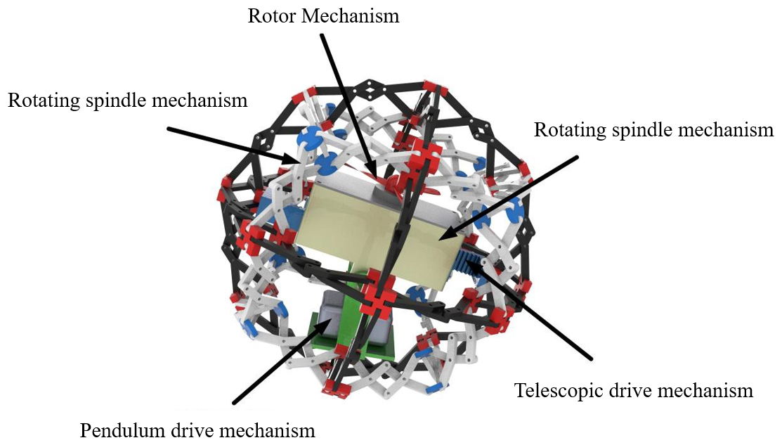
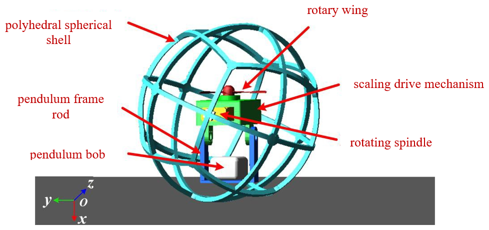
Figure 1 shows the overall mechanism of the RPSR, which is primarily composed of five components: the polyhedral shell mechanism that directly contacts the ground to perform rolling motion with a single-degree-of-freedom (DOF) deployable deformation function, the rotating-main-shaft mechanism that adjusts the RPSR's center-of-mass position to generate forward thrust, the pendulum drive mechanism that rotates around an axis perpendicular to the direction of the rotating main shaft for steering, the rotor mechanism that increases the normal contact force between the RPSR and the ground to assist in linear motion and steering while improving rolling stability, and the telescopic drive mechanism that generates synchronous thrust on both sides along the direction of the rotating main shaft to deform the reconfigurable polyhedral shell.
2.1 Design of reconfigurable polyhedron mechanism based on Hoberman sphere
The design method of the reconfigurable polyhedral mechanism usually inserts modular rods into the vertices, edges, or faces of the polyhedral base to construct a closed spatial geometric structure. According to the deformation form, common geometric structures include Hoberman sphere motion and radial reciprocating motion, which are divided into regular and semi-regular polyhedral structures according to the shape of the polyhedron (Wei et al., 2014). Considering the isotropic characteristics of the spherical structure, this paper designs a reconfigurable spherical-shell mechanism based on a regular polyhedron. The design ideas of the reconfigurable polyhedral mechanism are as follows:
- 1.
Select a regular polyhedron and find the symmetry axes through its centroid–vertex and centroid–face center pairs.
- 2.
Design the angle element according to the angle of the axis.
- 3.
Insert the angle element into the vertices of the polyhedron and their adjacent faces in sequence.
- 4.
Merge the repeatedly inserted transaction elements.
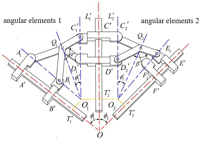
As shown in Fig. 2, the angled element connects the coupler and the coupler at Q1 through a hinge, and the coupler and the rod are connected at Q2 by a hinge. In the deformed state, the two pairs of angled elements are connected at C′ and D′ by revolute joints. As the mechanism deforms, points A′ and B′ translate along line OA′; points E′ and F′ translate along line OE′; points Q1 and Q2 translate along lines OQ1 and OQ2, respectively; and points C′ and D′ translate along line OC′. To enable the angled elements to realize the folding and unfolding function, the length and angle of each coupler must meet the following constraints:
where n1 and n2 are the proportional coefficients of the rod length.

Figure 2Structural diagram of two pairs of angular elements. (a) Unfolded configuration. (b) Folded configuration.
The lengths of the rods and the angles are shown in Fig. 2. Since the spatial folding–unfolding mechanism studied in this topic is to realize rolling motion, the symmetry of the mechanism should be considered during design. At this time, if n1 = n2 = 1, the angle element mechanism can be transitioned from Fig. 2a to Fig. 2b, and the following relationship exists:
Once the size parameters of the mechanism are defined, the difference between the squared lengths of the coupler links C′Q1 and C′Q2 remains constant. Additionally, and are fixed constants, whereas OO′ acts as a variable parameter during folding and unfolding. To ensure the validity of the equation, the following constraints must be satisfied:
Based on the geometric constraints of the mechanism, ≅ . In ΔA′OQ1, by the sine theorem, = . Combining the congruence relation and spatial geometric correlation of the polyhedral shell, sin ∠Q1A′O = = sin ∠Q1D′O. Applying the sine theorem to ΔQ1OD′ yields = . If A′Q1 = Q1D′ is satisfied, = is derived through equation substitution and simplification, which clarifies the angular coordination law of key hinge points and provides a theoretical basis for mechanism control and optimization.
As shown in Fig. 3, a single-degree-of-freedom planar folding–unfolding mechanism is composed of two pairs of symmetrically arranged angled elements and three pairs of inner- and outer-ring sliders, and the folding–unfolding deformation of the mechanism can be achieved through only one drive. The extension lines of the hinge points A1B1 and intersect at point O1. The angled elements intersect at Q1. During the folding–unfolding deformation, Q1 is always located on the straight line Q1O1, and the hinge points A1, B1 and , perform reciprocating linear motion along the straight lines A1O1 and , respectively. Similarly, the design of the angled element on the right is the same as above. Its deformation mode is as follows: when the distance between the inner- and outer-ring sliders decreases, the mechanism expands and unfolds and vice versa (the mechanism shrinks and folds). At the same time, due to the motion transmission characteristics of the angled-element group, the change in the distance between any adjacent inner- and outer-ring sliders is consistent, and the installation position of the drive device can be flexibly selected according to design requirements.
To ensure the isotropy of the deployable mechanism during deformation, the dimensional parameters of the angulated elements should satisfy the following constraint conditions during the design process:
Equation (6) contains four design variables (, , O1Q1, and ) and two constraint equations, resulting in only two independent parameters. To fully determine all dimensional parameters of the deployable mechanism, any two variables can be assigned, and the remaining parameters can be calculated accordingly. It is noteworthy that, when ϕ = , the mechanism achieves a higher scaling ratio, and the line O1Q1 coincides with the angle bisector of . From the formula ϕ + α′ = π, the second constraint equation can be simplified to
In the design process of the angular-element group, the size of α′ can be determined first. Therefore, by arbitrarily designing one of the edges of ΔOOT′, the single-degree-of-freedom planar-deployable mechanism can be completely obtained through calculation.
Based on the above analysis, different types of angular-element groups can be designed. As shown in Fig. 4, there are two spatial structural forms, namely the three-angular-element group and the four-angular-element group. Each branch chain has two pairs of angular elements, which have a larger folding ratio compared to a single pair of angular elements.
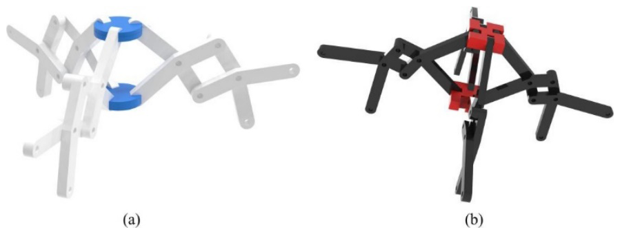
Figure 4Angular-element groups. (a) Triangle-based mechanism with three angled elements. (b) Quadrangle-based mechanism with four angled elements.
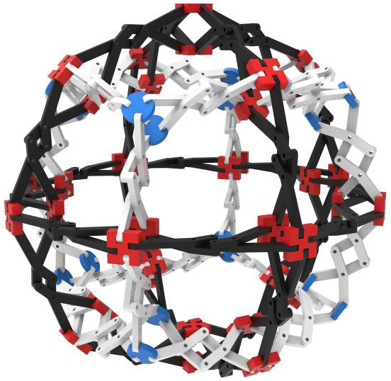
By further connecting 16 quadrangular-element groups in specific parallel and perpendicular configurations and incorporating 8 triangular-element groups at the interstitial positions of the quadrangular framework, a spatial framework for a polyhedral spherical shell can be constructed. As illustrated in Fig. 5, the three-dimensional model demonstrates the polyhedral-spherical-shell mechanism in its deployed state. Figure 5 shows the three-dimensional model of the polyhedral-spherical-shell mechanism in the unfolded state.
2.2 Design of drive modules and deformation units
The deformation units collaborate with the drive modules through a key design principle: they maintain the stability of the center of mass during reconfiguration by employing structural symmetry rather than actively shifting it for locomotion. The mechanism adopts a symmetric gear–rack configuration, where a spur gear driven by a motor engages with two racks in opposite directions. This ensures synchronized linear displacements, leading to uniform expansion or contraction of the polyhedral shell and keeping the center of mass beneath the geometric center. With this design, deformation and locomotion are decoupled: the deformation unit alters the robot's size while preserving a stable mass distribution, which, in turn, allows the drive modules – such as the pendulum mechanism – to effectively generate rolling and steering torques across different configurations. To actuate the reconfigurable polyhedral shell described in the previous section for both rolling and deformation and to precisely control the robot's motion, a compact and efficient internal drive and actuation unit is essential. This unit must not only provide the primary propulsion for locomotion but also execute the shell's expansion and contraction commands with precision. Furthermore, it facilitates motion stability by adjusting the internal mass distribution. The following section details the design of this core module, which integrates the pendulum mechanism for primary drive force, the rotor mechanism for adjusting normal contact forces and assisting steering, and the gear–rack transmission for synchronous shell reconfiguration.
This paper investigates the RPSR driven by a dual-rotational-axis single-pendulum mechanism. The robot achieves locomotion through internal multi-motor actuation for center-of-mass adjustment, where the frictional interaction between its polyhedral spherical shell and the ground critically determines motion stability and terrain adaptability. To enhance performance, an inverted rotor mechanism has been designed to improve ground contact and motion stability by increasing normal contact forces without adding mass. The inverted rotor mechanism is illustrated in Fig. 7. This system simultaneously provides auxiliary propulsion and enables precise steering fine-tuning through angular momentum conservation, comprehensively optimizing the robot's dynamic performance.
In rotor operation, as shown in Fig. 6a, the rotor typically generates upward lift. To increase friction, it is necessary for the rotor to produce a downward counteracting lift, the mechanism of which is illustrated in Fig. 6b. Here, V0 denotes the velocity of the incoming airflow, FR is the drag force acting parallel to the airflow direction, and FL is the lift force acting perpendicular to the airflow direction. The magnitudes of the drag and lift forces can be determined by the following expressions:
where ρ0 denotes the air density; c′ is the chord length of the blade element with thickness dr; and CR and CL represent the sectional drag and lift coefficients, respectively.
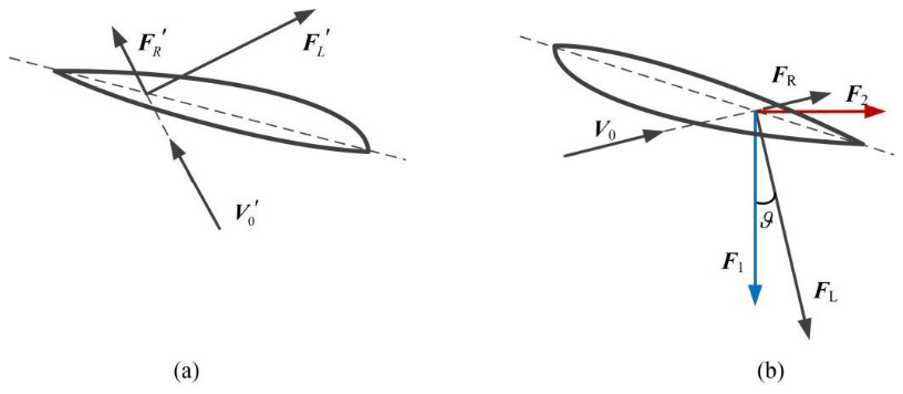
Figure 6Vector diagram of leaf element stress analysis. (a) Front-mounted rotor. (b) Reverse-mounted rotor.
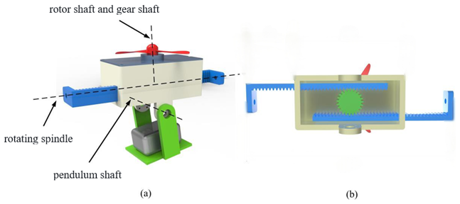
Figure 7Drive module and deformation unit. (a) Axonometric view highlighting motor–gear–rack layout. (b) Bottom view showing symmetric rack displacement.
As shown in Fig. 6b, by projecting the aerodynamic forces FR and FL along the horizontal and vertical directions, the downward normal force F1 generated by a blade element and the resistive force F2 opposing the motor rotation can be obtained. Considering a total of K blades, the total axial thrust Ftotal and the torque M′ generated by the rotor blades are given by
where r denotes the distance from the blade element to the rotor axis, and θ is the angle between the lift force and its vertical projection.
The deformation–actuation module was investigated, and precise control of the center-of-mass (CoM) position was identified as the fundamental requirement for motion smoothness. The deformation–actuation module is illustrated in Fig. 7b. A symmetric involute spur gear–rack transmission was implemented. In this design, motor-driven rotation of an involute spur gear generates high-precision, synchronous linear displacement of two opposing racks, thereby enabling scalable deformation of the single-degree-of-freedom reconfigurable polyhedral shell; geometric symmetry exploitation constitutes the innovative strategy for CoM regulation. Dynamic stability is maintained throughout the entire deformation sequence by ensuring that the CoM remains directly beneath the geometric center of the spherical shell without auxiliary balancing devices. Moreover, the inherent characteristics of mechanically meshed transmission markedly enhance structural compactness and operational reliability.
2.3 Design principles and specifications
The integration of the reconfigurable polyhedral shell with the internal drive and deformation modules was guided by a set of fundamental principles and performance requirements. These criteria constrained the structural design and also served as the basis for subsequent dynamic analysis, simulations, and prototype validation. The external shell of the robot adopts a Hoberman-inspired polyhedral configuration, which ensures large-scale deployment while maintaining geometric closure in both contracted and expanded states. The design emphasizes modularity and symmetry so that the folding–unfolding process can be realized through coordinated single-degree-of-freedom motion. This guarantees stable geometry during deformation, which is essential for achieving smooth rolling locomotion.
A key requirement of the system is to preserve stability by keeping the center of mass close to the geometric center of the shell during reconfiguration. To achieve this, the deformation units employ a symmetric gear–rack transmission that enables synchronous expansion and contraction. Functionally, the robot combines a pendulum-based drive for primary rolling locomotion with a rotor-assisted system. The pendulum provides propulsion on flat and inclined surfaces, while the rotor enhances normal ground contact force, improves traction, and contributes to steering stability.
The structural design was developed to meet several performance targets. These include maintaining a linear-motion deviation of less than 5 % during straight-line rolling, a minimum obstacle-crossing capability of 30 mm, and a rolling speed not lower than 0.3 m s−1 on flat ground. In addition, the deployable shell diameter is adjustable between 400 and 500 mm, while the total mass does not exceed 5 kg, ensuring compactness and portability.
To actuate the reconfigurable polyhedral shell described in the previous section for both rolling and deformation and to precisely control the robot's motion, a compact and efficient internal drive and actuation unit is essential. This unit must not only provide the primary propulsion for locomotion but also execute the shell's expansion and contraction commands with precision. Furthermore, it facilitates motion stability by adjusting the internal mass distribution. The following section details the design of this core module, which integrates the pendulum mechanism for primary drive force, the rotor mechanism for adjusting normal contact forces and assisting steering, and the gear–rack transmission for synchronous shell reconfiguration.
3.1 Feasibility analysis of the polyhedral spherical robot's motion
For a mobile robot with a partially incomplete spherical shell, its ability to achieve continuous rolling on a planar surface is analyzed. Figure 8 illustrates the tumbling-roll gait. Assuming ideal conditions, the robot obeys the conservation of mechanical energy: the potential energy is maximal and the kinetic energy is minimal when the center of mass reaches its highest point. Continuous rolling is feasible if the minimum kinetic energy in this configuration is non-negative.
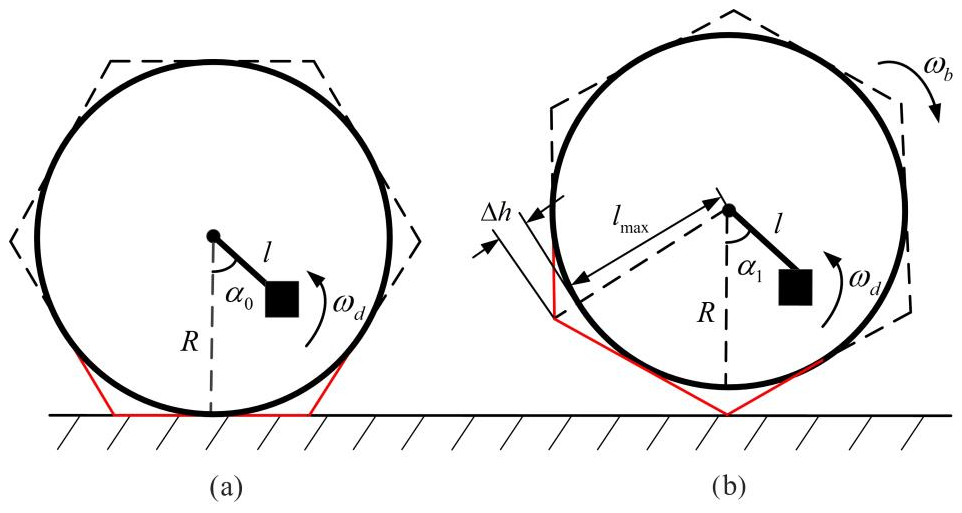
Figure 8Rolling of the polyhedral spherical robot: (a) initial configuration, (b) rolling configuration.
Taking the initial stationary state as a reference, the motor drives the pendulum to rotate, allowing it to acquire angular velocity and gravitational potential energy, which induces a shift of the overall center of mass and generates a tendency for rolling in the direction of the displacement. This critical configuration is defined as E0.
In the E0 state, the system possesses a total mechanical energy Etotal, expressed as
where Tini denotes the total kinetic energy of the system, and Vini denotes the total potential energy of the system. At this moment, both gravitational potential energy and kinetic energy are zero. Therefore, the following relation holds:
where J2, wd, and md denote the moment of inertia of the pendulum about the geometric center of the polyhedral spherical robot, the angular velocity of rotation, and the mass of the pendulum, respectively; hb and α0 represent the vertical height of the mobile robot from the ground and the critical rotation angle at the rolling threshold state E0; mb, hb, and R denote the mass of the spherical shell of the mobile robot, the vertical height of its centroid from the ground, and the radius of the shell, respectively; and l and g are the pendulum length and the gravitational acceleration.
As shown in Fig. 8b, when the overall center of mass of the robot reaches its highest critical position, the gravitational potential energy attains its maximum value. At this moment, the total mechanical energy of the system, denoted as , is expressed as follows:
where Δh represents the dimensional difference between the approximate spherical radius of the polyhedral shell and the external polygonal diagonal radius, ωb denotes the angular velocity of the polyhedral spherical mobile robot during rolling, and α1 is the angle between the pendulum and the vertical line through the centroid of the spherical shell when the center of mass reaches its highest position.
The variation of the system's mechanical energy before and after this process is caused by the combined work of the motor driving force and the frictional resistance, denoted as Wdriveand Wfric, respectively. If the rolling velocity of the spherical robot is v, the total work W′ is expressed as follows:
where Pw denotes the motor power, Fm is the magnitude of the frictional force, and s represents the displacement of the robot.
From the above analysis, it can be concluded that the necessary condition for the polyhedral spherical mobile robot to achieve smooth rolling is ωb ≥ 0. To further examine whether rolling can occur, we assume ωb = 0. In this case, the mechanical energy is given by
The variation in mechanical energy, denoted as ΔE, is expressed as follows:
The variation of mechanical energy before and after rolling is caused by the combined work of the internal system and the external environment. Therefore,
By combining Eqs. (14) and (16), the following relation can be obtained:
This equation represents the critical condition for the polyhedral spherical mobile robot to initiate rolling. The factors influencing this condition include the motor power parameters, ground friction, and the mass and structural parameters of the spherical robot. Specifically, the critical condition requires that the cosine value of α0 on the left-hand side of the equation must not exceed that of the right-hand side. Since, within the interval (0,90°), the cosine function is inversely related to the angle, the minimum critical value of the initial swing angle can therefore be determined based on Eq. (18).
As illustrated in Fig. 9, the factors influencing the critical swing angle α0 of the polyhedral spherical robot during critical rolling are as follows. The critical swing angle is negatively correlated with the motor power Pw, the contact friction force Fm of the polyhedral shell, and the geometric shape parameter Δh, while it is positively correlated with the pendulum mass md. Therefore, to enhance the motion responsiveness and maneuverability of the polyhedral spherical robot, one may increase the motor power, improve the contact friction between the shell and the ground, or adjust the pendulum mass.
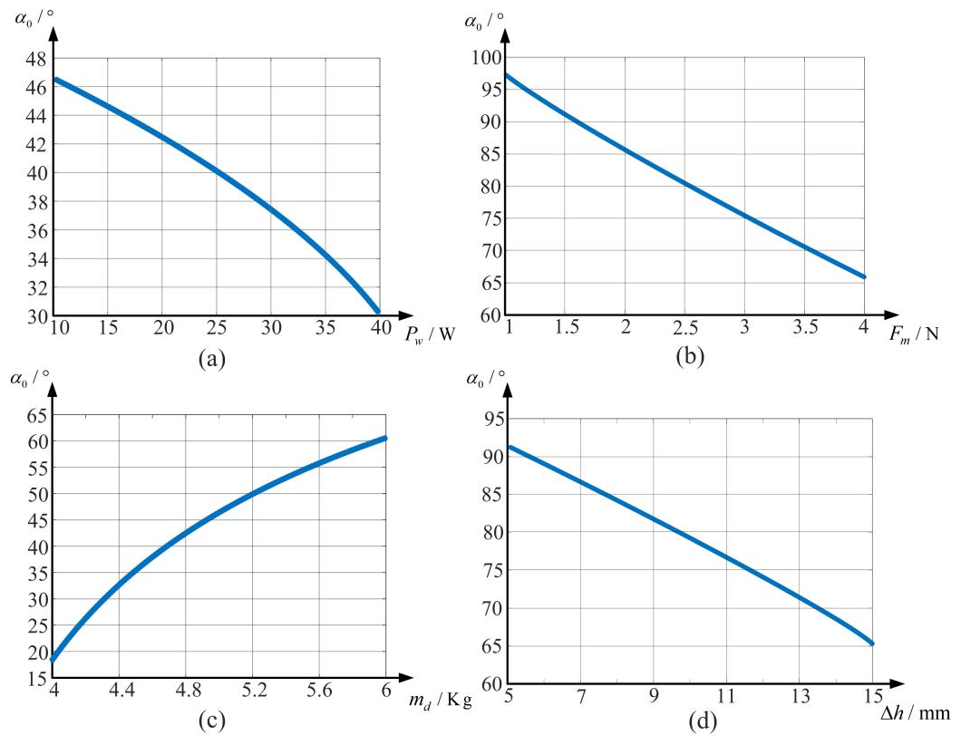
Figure 9Factors influencing the critical rolling condition: (a) power parameters, (b) friction parameters, (c) mass parameters, (d) geometric parameters.
It should be noted that swing angles greater than 90° are invalid for effective rolling. As shown in Fig. 9b, when the contact friction force is less than 1.6 N, loss of control occurs. Thus, a minimum friction force must be ensured to achieve continuous rolling. In addition, the geometric parameter Δh reflects the outer contour shape of the polyhedral shell. Once the shell structure is determined, the number of polygonal edges in the outer contour is fixed. A larger Δh corresponds to a smaller inscribed circle diameter. From the relationship between the critical swing angle and Δh shown in Fig. 9d, it can be concluded that a smaller robot diameter makes it easier for rolling to occur.
3.2 Analysis of the motion performance of the polyhedral spherical robot on the flat ground
The outer shell of RPSR was maintained in multipoint contact with the ground, whereby the frictional forces arising at the interface were harnessed as the primary driving traction. An inverted rotor assembly was implemented and combined with the pendulum-driven actuation principle to generate an obliquely downward force along the forward axis; this force both increased the normal contact pressure between the spherical shell and the ground – thereby enhancing locomotion stability – and provided a forward thrust to improve travel speed.
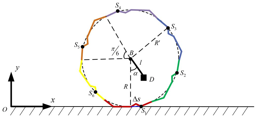
As shown in Fig. 10, a simplified model of the polyhedral spherical robot is established in a Cartesian coordinate system, where the horizontal and vertical directions are defined as the x and y axes, respectively. The robot shell is represented by six identical non-circular arc polyline segments approximating a sphere of radius R, with geometric center B and counterweight offset distance l. The robot's motion can be described as successive rotations around six critical contact points (S1–S6), each at a distance R′ from B. The pendulum angle relative to the vertical line through B is denoted as α. s is determined by the geometric parameters of the polyhedral spherical shell.
A comprehensive force analysis of the reconfigurable polyhedral spherical robot was conducted by means of the Newton–Euler method. The force vectors acting on the polyhedral shell are illustrated in Fig. 11a, and the corresponding force diagram for the pendulum mechanism is presented in Fig. 11b.

Figure 11Simplified planar motion model of the RPSR. (a) Force distribution on the polyhedral shell. (b) Force and torque analysis of the pendulum mechanism.
The following symbols are used in the dynamic equations:
-
mb – mass of the polyhedral spherical shell
-
md – mass of the pendulum
-
– vertical component of the resultant force generated by the rotor-assisted mechanism
-
– horizontal component of the resultant force generated by the rotor-assisted mechanism
-
abx, adx – translational accelerations of the spherical shell and pendulum in the x-axis direction
-
aby, ady – translational accelerations of the spherical shell and pendulum in the y-axis direction
-
M – reaction torque of the drive motor
-
FN – support force from the ground
-
f – friction force from the ground
-
Fx, Fy – action forces from the pendulum on the shell
-
, – reaction forces from the shell on the pendulum
-
α0 – rotation angle of the spherical shell around point Si (i = 1, 2,…, 6)
-
J1 – moment of inertia of the spherical shell around point Si
-
J2 – moment of inertia of the pendulum around the geometric center B of the spherical shell.
Force analysis of the polyhedral spherical shell is as follows:
Force analysis of the pendulum is as follows:
By combining Eqs. (19) and (20), the dynamic equations of the polyhedral spherical mobile robot moving in the horizontal plane can be obtained:
3.3 Analysis of the obstacle-crossing performance of the polyhedral spherical robot
To investigate the obstacle-traversal performance of the reconfigurable polyhedral spherical robot, a dynamic model of the crossing process is established under the following simplifying assumptions:
- 1.
Obstacles are fixed, with known geometry and dimensions.
- 2.
During traversal, no slip occurs at the contact points between the spherical shell and either the horizontal ground or the obstacle, and the shell remains rigid.
- 3.
The robot has sufficient power and maneuverability to execute the maneuverer.
As in the obstacle-free rolling analysis, the robot is partitioned into two subsystems for force analysis, as shown in Fig. 12, where the obstacle height is h and the reaction force at the obstacle contact is N.
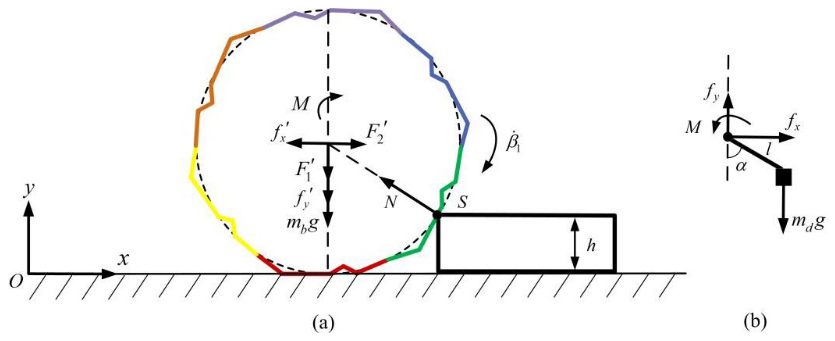
Figure 12Force analysis of obstacle crossing. (a) Force distribution on the polyhedral shell. (b) Force and torque interaction of the pendulum.
The force equilibrium of the polyhedral shell was established by applying the Newton–Euler method under the no-slip assumption. Taking moments about the obstacle contact point leads to the following kinematic relationship:
where N is the support force exerted by the obstacle on the polyhedral spherical shell, and is the angular velocity of the robot around the obstacle-crossing contact point.
By combining Eqs. (20) and (22), the dynamic equation of the polyhedral spherical mobile robot when crossing an obstacle in the plane can be obtained:
where axy = (abxcos α+abysin α), and Ft = .
Environmental adaptability is exhibited by the RPSR's scalable, partial-spherical-shell architecture; however, obstacle-climbing performance remains constrained by both obstacle height and motion stability factors. Although size adjustment for different obstacles is enabled via shell self-reconfiguration, the finite deformation range precludes surmounting excessively tall barriers, and unintended lateral rolling or attitude tilt is induced by the partial-spherical-shell structure upon obstacle contact, presenting dynamic-instability risks. Hence, path planning must integrate deformation strategies for pre-evaluating obstacle height thresholds, and obstacle traversal stability must be enhanced through optimized structural symmetry and center-of-mass regulation.
3.4 Influence of the telescopic drive mechanism and rotor mechanism on the obstacle-crossing ability
Below, a theoretical analysis of obstacle height capability and traversal stability is conducted. Taking moments about the contact point S between the RPSR's polyhedral shell and the obstacle yields
The rotor-assisted mechanism of the RPSR generates an external force, ≠ 0 and ≠ 0. Let (R−h)2 = t; then Eq. (24) can be simplified to
Let = t, and the solution is
That is, when 0 ≤ holds, the inequality ≥ t always holds, and we have
Furthermore, the following can be obtained:
When (R−h)2 ≥ is satisfied, the inequality ≤ t always holds. From Eq. (25), this can be rearranged to get
Considering the effect of the rotor-assisted mechanism, the obstacle-crossing conditions of the RPSR change. The spherical-shell radius R can be adjusted as follows:
- 1.
There is a parameter related to the radius R of the polyhedral spherical shell, denoted as t0. When the square of the difference between the obstacle height h and the spherical-shell radius R is not greater than the parameter t0, the polyhedral spherical robot has a minimum-limit value for the height of crossing the obstacle. This limit value is related to the mass parameters, size parameters, aerodynamic parameters generated by the rotor mechanism, and pendulum angle parameters of the robot. That is, when the spherical-shell radius is close to the obstacle height, there is no need to overly increase the spherical-shell radius for the robot to successfully cross the obstacle. Since it has a minimum-limit crossing height, only the spherical-shell radius needs to be adjusted so that the minimum-limit height is greater than the obstacle height.
- 2.
When the square of the difference between the obstacle height h and the spherical-shell radius R is greater than or equal to a certain parameter t0 related to the radius R of the polyhedral spherical shell, the polyhedral spherical robot has a maximum-limit value for the height of crossing the obstacle. That is, when the spherical-shell radius is much larger than the obstacle height, the spherical-shell radius cannot be overly reduced for the robot to cross the obstacle stably. Since it has a maximum-limit obstacle-crossing height, if the spherical-shell radius is adjusted too small, the robot will not be able to cross the obstacle smoothly. As shown in Fig. 13, this depicts the influence of the vertical component and the horizontal component of the force generated by the rotor on the obstacle-crossing height of the robot. Here, the spherical-shell radius R = 0.2 m. The minimum obstacle-crossing height rises with the increase in , showing a positive-correlation trend, while has a negative effect on the obstacle-crossing height and is not conducive to the increase in the obstacle-crossing height.
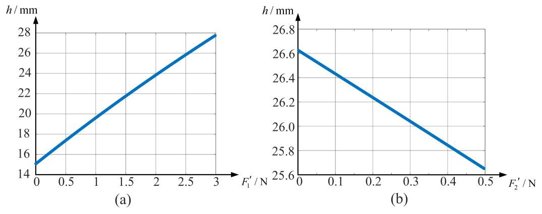
Figure 13Minimum obstacle-crossing height during rotor action. (a) Influence of vertical force component . (b) Influence of horizontal force component .
Assume that the pendulum rotates at a constant speed; that is, the torque of the pendulum relative to the geometric center of the polyhedral spherical shell is balanced with the torque generated by the motor. The limiting condition of the driving torque can be derived from Eq. (24).
The maximum value of the motor driving torque of the single-pendulum spherical robot is mdgl. As can be seen from Eq. (30), the larger the overall mass of the RPSR, the greater the driving torque required for the motor. Similarly, the rotor mechanism will also affect the driving torque required when the robot crosses an obstacle, imposing higher requirements on the motor driving torque. Figure 14 shows the influence of the rotor mechanism on the driving torque of the RPSR. At this time, the radius of the polyhedral spherical shell R = 0.2 m, and the obstacle-crossing height h = 0.02 m.
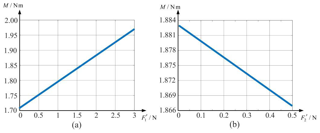
Figure 14Driving torque during rotor action M: (a) vertical component force , (b) horizontal component force .
The rationality of the RPSR's structural design and the validity of its dynamic model were verified via simulation experiments. Owing to the large number of components in the polyhedral shell, the shell was simplified for computation. Figure 15 shows the simplified robot model as implemented in the simulation software. Unlike typical spherical robots that roll through single-point contact, the RPSR's locomotion occurs via multipoint contact.
In this simulation model, the polyhedral shell has a mass of 0.8 kg and a radius of 0.25 m, the drive mechanism has a mass of 1.2 kg, and the pendulum arm length is 0.2.
4.1 Linear-motion simulation on flat ground
Due to the incomplete-shell configuration of the RPSR, a lateral-drift tendency is induced during forward rolling. The robot's motion trajectory is shown in Fig. 16, where the path exhibits translation along the y axis accompanied by a positive displacement along the z axis.
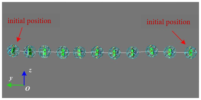
Figure 17 presents the post-processed simulation results for z-axis displacement. From the Z1 curve, it is observed that, during the first 2.5 s of motion, no significant displacement along the z axis occurs. Between 2.5 and 5 s, a self-correctable drift takes place, and, by 5 s, the trajectory closely aligns with the desired path. However, from 5 to 7.5 s, the z-axis displacement increases rapidly and continues to grow until 10 s. Although the trajectory partially self-corrects from 2.5 to 12.5 s, the robot is no longer able to maintain stable straight-line motion thereafter, and a sharp increase in z-axis drift is observed at 15 s.
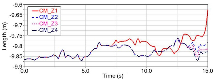
Further analysis reveals that the maximum offset from the target distance during the process is 0.23 m. However, within the same time period, the effective traveling displacement of the robot in the y-axis direction is 5.3 m. The maximum offset displacement accounts for approximately 4.3 % of the effective displacement. Therefore, the robot has a relatively good linear-motion ability.
As the rolling distance of the robot increases, it becomes more difficult for it to maintain linear motion. Thus, timely correction of the moving direction is necessary. The robot's steering task is mainly accomplished by the pendulum swinging around an axis perpendicular to the direction of the main rotation axis. In this research project, a rotorcraft mechanism is designed. Based on the principle of conservation of angular momentum, during the traveling process, the robot can make fine-tuned turns through the rotorcraft mechanism, which can further improve its linear-motion ability. The results after fine-tuning are shown as curves Z2, Z3, and Z4 in Fig. 17. The displacement of the offset in the positive z-axis direction gradually decreases. The adjustment process is as follows.
To mitigate the negative z-direction drift observed around 7.5 s, the rotor mechanism was actuated at 7 s to reorient counterclockwise, thereby reducing the z-axis deviation as shown in curve Z2 in Fig. 16. A residual offset at 12.5 s necessitated a second fine adjustment of the rotor, yielding the Z3 trajectory. After these two interventions, the RPSR's straight-line rolling capability was enhanced, and subsequent incremental corrections further converged the motion toward true linearity, as indicated by curve Z4; the center-of-mass z coordinate at the beginning and end of the trial remained essentially unchanged.
4.2 Simulation of obstacle-crossing motion
Obstacle traversal capability is a key indicator of a mobile robot's environmental adaptability. In this section, obstacle-climbing straight-line maintenance, traversal stability, and traversal adaptability were evaluated via simulation. The obstacle height was set to 0.015 m, and the pendulum's angular velocity was set to 60° s−1. The simulation was divided into three phases – speed adjustment, obstacle crossing, and stability recovery – as shown in Fig. 18.
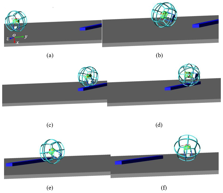
Figure 18Obstacle-crossing motion simulation. (a–b) Speed adjustment phase. (c–d) Obstacle-crossing phase. (e–f) Stability recovery phase.
In the speed adjustment phase, as shown in Fig. 18a and b, the pendular bob was driven by the main shaft to swing forward, imparting initial kinetic energy to the RPSR and reducing the gap in relation to the obstacle. During the obstacle-crossing phase, as shown in Fig. 18c and d, the shell leveraged inertial force to vault over the barrier; the maximum climbable height was determined by both rolling velocity and shell radius. In the stability recovery phase, as shown in Fig. 18e and f, corrective pendular actuation was applied following obstacle clearance to restore stable, straight-line motion.
During the obstacle-crossing process, the robot moves forward along the transverse y axis. Due to the characteristics of the polyhedral spherical shell's shape, vibration will occur along the vertical x axis, and there will also be an offset along the longitudinal z axis. Its position change can be reflected by the geometric center of the polyhedral spherical shell. Figure 19 shows the motion trajectories of the geometric center in the transverse and longitudinal directions.
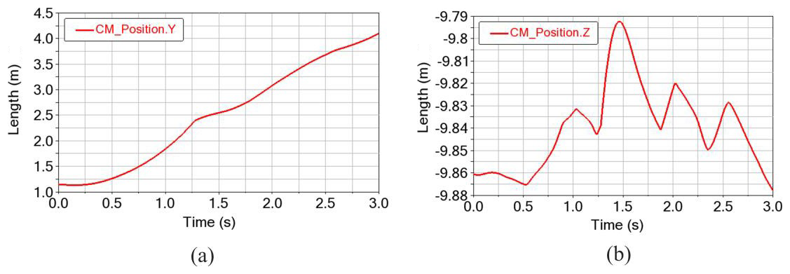
Figure 19Position change of the geometric center. (a) Lateral displacement. (b) Longitudinal displacement.
As indicated by the simulated trajectory results, the RPSR completes obstacle traversal within 3 s, covering 2.8 m of forward displacement with a maximum lateral deviation of 0.08 m, thereby demonstrating excellent straight-line performance during both planar motion and obstacle crossing. Furthermore, according to the geometric-center position curve, the traversal process can be partitioned into two phases: in phase I, from 0 to 1.25 s, the robot attains its initial velocity and approaches the obstacle; in phase II, lasting approximately 0.75 s, the process of contact and vaulting occurs, after which the RPSR continues in straight-line motion and preserves its intrinsic motion stability.
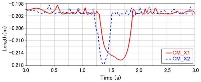
Figure 20 shows the post-simulation results of the geometric center of the RPSR jittering along the x-axis direction. To test the impact of speed on the obstacle-crossing stability of the robot, a control group with a pendulum angular velocity of 70° s−1 is set. From the displacement curves, it can be seen that the maximum jitter displacement amounts are 0.018 and 0.020 m, which are higher than the height of the obstacle at 0.015 m. The vibrational jitter of the geometric center in this direction affects the motion stability of the robot and the reliability of its internal structure. Therefore, it should be controlled within a certain range as much as possible. From the comparison of the two curves, it can be found that an increase in the moving speed will increase the maximum jitter displacement amount, which is not conducive to the motion stability of the robot. However, it will shorten the contact time between the polyhedral spherical shell and the obstacle, enabling the robot to climb over the obstacle more quickly.
Through the analysis of the above-mentioned simulation results, the main influencing factors of the obstacle-crossing height and obstacle-crossing stability of the RPSR can be found. Following this, it is necessary to analyze the obstacle-crossing adaptability. Under the condition that other parameters remain unchanged, the height of the obstacle is set to 0.03 m, and the simulation result of the component of the motion trajectory of the polyhedral spherical robot on the x axis is shown in Fig. 21a.
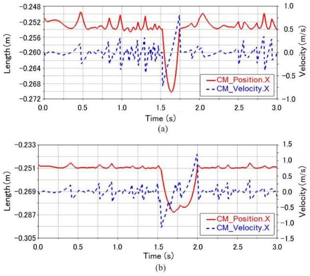
The maximum fluctuating displacement is only 0.021 m. However, under ideal conditions, this displacement should be no less than the actual height of the obstacle, which is 0.03 m. Therefore, in this case, the robot cannot cross the obstacle, and the obstacle-crossing process fails. To successfully complete the obstacle-crossing motion, taking advantage of the deformable structural characteristics of the polyhedral spherical shell, the radius of the robot is increased from 0.2 to 0.25 m. The post-processing results of its motion simulation are shown in Fig. 21b. The maximum displacement along the direction of the obstacle height is 0.037 m, which is greater than the height of the obstacle itself. Therefore, under the condition of an increased obstacle height, the polyhedral spherical robot can still effectively complete the obstacle-crossing motion. During the smooth-motion process, a fixed angle α is maintained between the pendulum and the ground. The normal force F1 and thrust F2 exerted by the rotor on the structure of the main rotation axis have the following relationships with the vertical force and horizontal force acting on the RPSR:
Based on the formula for the obstacle-crossing driving torque M in Eq. (30) and the parameters of the simulation environment, assume that the radius of the spherical shell of the RPSR R = 0.25 m, the height of the obstacle h = 0.02 m, = 2, and = 0.1. Then, the driving torque M required for the robot to cross the obstacle can be calculated. Moreover, the correctness of the theoretical analysis is verified through simulation experiments. The post-processing results of the simulation are shown in Fig. 22.

The simulation results have verified the feasibility of the RPSR's design and its significant motion potential in a virtual environment. However, to ultimately confirm the robot's performance in the real physical world – accounting for practical factors such as manufacturing tolerances, friction, and material properties – the fabrication and testing of a physical prototype are indispensable. This chapter details the assembly of the prototype and presents a series of experiments designed to test its linear motion, steering control, and obstacle-crossing capabilities. The goal is to compare the theoretical analysis and simulation data with real-world performance, thereby fully evaluating the practical value of this self-reconfigurable spherical robot.
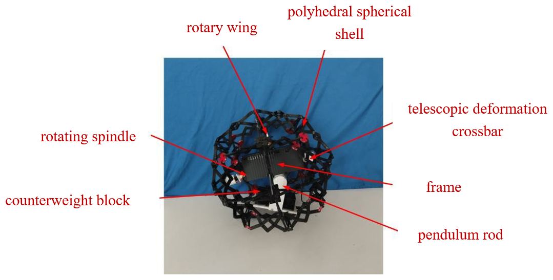
By assembling all components, the overall prototype of the RPSR can be obtained. It is mainly composed of seven parts, namely the battery counterweight block, the rotating main shaft, the rotor, the polyhedral spherical shell, the telescopic deformation crossbar, the frame, and the pendulum rod, as shown in Fig. 23.
5.1 Linear-motion experiment
The RPSR was placed in an experimental field with side lengths of 2.0 m × 2.0 m, and its radius was set to R = 250 mm. The rolling motion of the robot on the ground was then observed, as shown in Fig. 24.
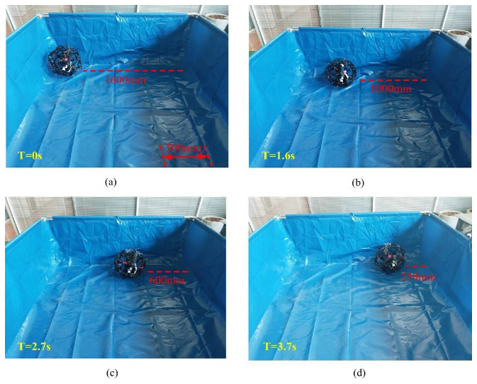
At T = 0 s, the robot was in a stationary state. By controlling the 42-step-by-step motor, the rotating main-shaft mechanism was made to swing at a motor speed of 30° s−1. As the swing angle increased, the center of mass of the robot moved forward, and, at this time, the robot had a tendency to roll forward. At T = 1.6 s, the robot had traveled 600 mm, and there was no significant deflection in the moving direction. At T = 2.7 s, the robot continued to travel 400 mm. At T = 3.7 s, the robot was approaching the edge of the experimental field. The swing angle of the motor was controlled to slow down the robot and gradually stop its rolling.
During the experiment, the RPSR kept rolling close to the edge of the experimental field. It showed good linear-motion retention and met the requirement of a linear-deviation navigation error during short-distance movement.
The rolling speed is an important indicator for measuring the motion performance of a spherical robot. In view of the target performance parameters of the RPSR, its rolling speed on hard and smooth ground was tested. Table 1 shows the time required for the robot to travel every 0.35 m during the process of rolling 1.4 m.
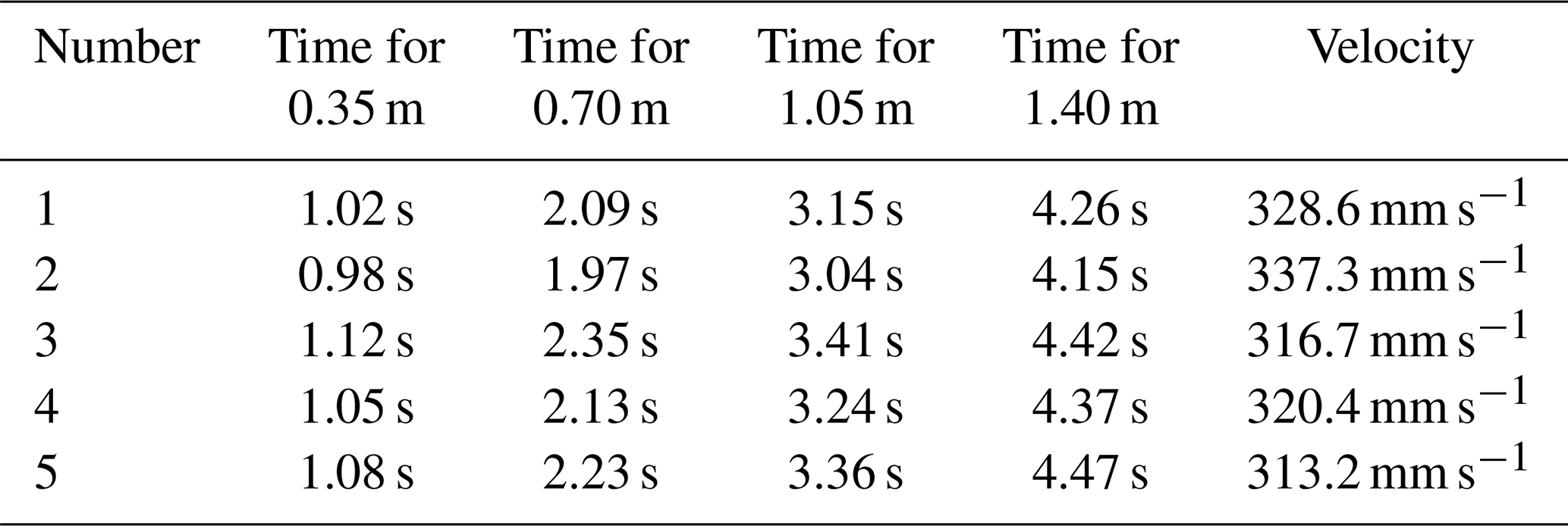
From the test results, it can be seen that, at this motor speed, the minimum moving speed of the robot is 313.2 mm s−1, which meets the preset target performance parameter of 300 mm s−1. It is close to the Adams simulation value of 353.3 mm s−1, with a relative error of 11.4 %.
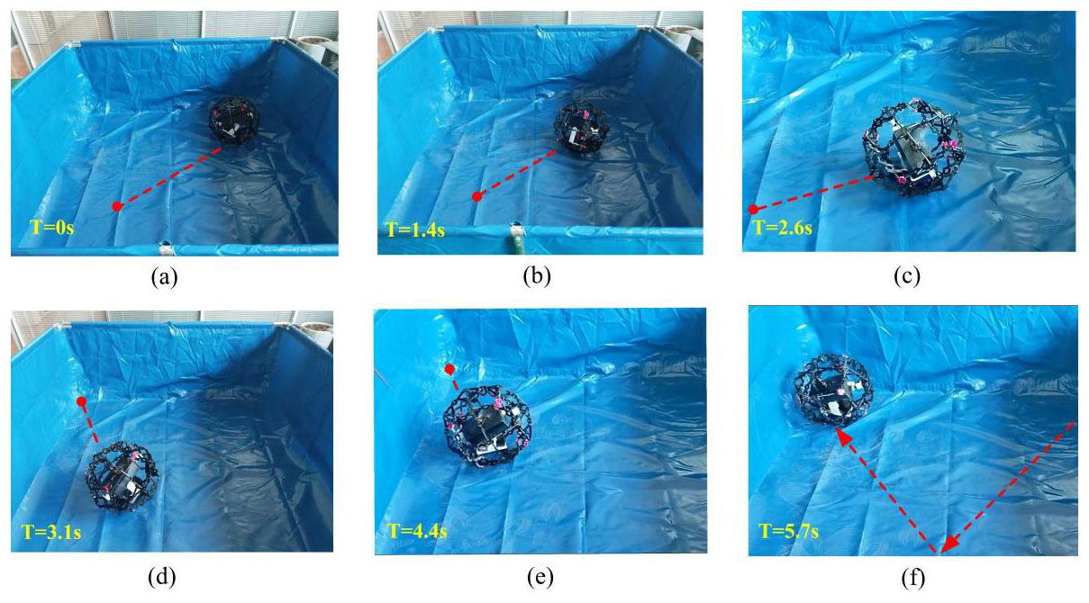
5.2 Steering-motion experiment
The steering-motion experiment of the RPSR is shown in Fig. 25. At T = 0 s, the robot starts to roll along the dotted-line direction from a stationary state. At T = 1.4 s, it continues to move in a straight line. To test the influence of the rotor mechanism on the motion, when it travels to T = 2.6 s, the brushless motor is controlled to rotate clockwise at a high speed. The polyhedral spherical shell instantaneously contracts slightly and remains stable. At the same time, the entire robot rotates slightly in the direction opposite to the motor rotation. At T = 3.1 s, the servo is controlled to make the pendulum swing around the direction of the rotating main shaft, and the moving direction of the robot changes. At T = 4.4 s, the robot maintains a straight-rolling state. At T = 5.7 s, when it approaches the edge of the experimental field, the robot and the rotor mechanism stop moving.
5.3 Obstacle-crossing motion experiment of the RPSR
To verify the obstacle-crossing ability of the RPSR, two sets of obstacles are set up in the experimental field in this section. The heights of the obstacles are 15 and 30 mm.
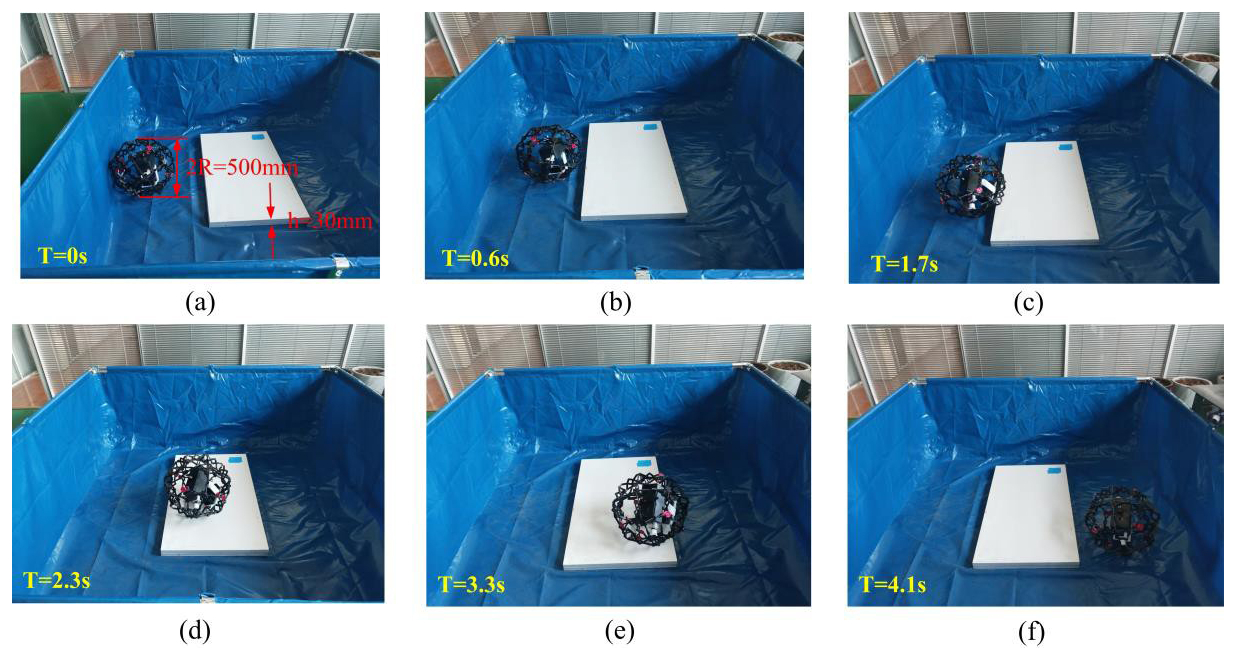
Shown in Fig. 26 is the experimental process of the robot crossing the 15 mm obstacle. At T = 0 s, the robot is in a stationary state. At T = 0.6 s, the robot gradually approaches the obstacle. At T = 1.8 s, the robot comes into contact with the obstacle, and the obstacle-crossing process begins. At T = 2.2 s, the robot climbs over the obstacle. At T = 3.5 s, the robot descends from the obstacle. At T = 4.3 s, the obstacle-crossing process is completed.
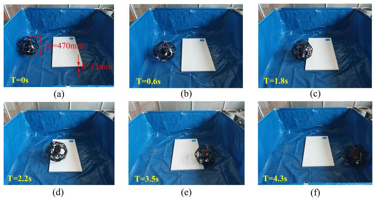
Figure 27 shows the experimental process of the robot crossing the 30 mm obstacle. The radius of the polyhedral spherical shell is expanded to 250 mm before crossing the obstacle. The two obstacle-crossing processes are basically the same, indicating that the polyhedral spherical robot has improved its obstacle-crossing ability and has good terrain adaptability by scaling the size of the spherical shell.
5.4 Error analysis
Based on the theoretical values, using the simulation values of the motion performance of the RPSR in Sect. 3, the relative error between the simulation values and the test values is calculated based on the test values. The radius of the robot is 250 mm, and the comparison of the robot's motion performance parameters is shown in Table 2.
Table 2Analysis and comparison of robot motion performance parameters.
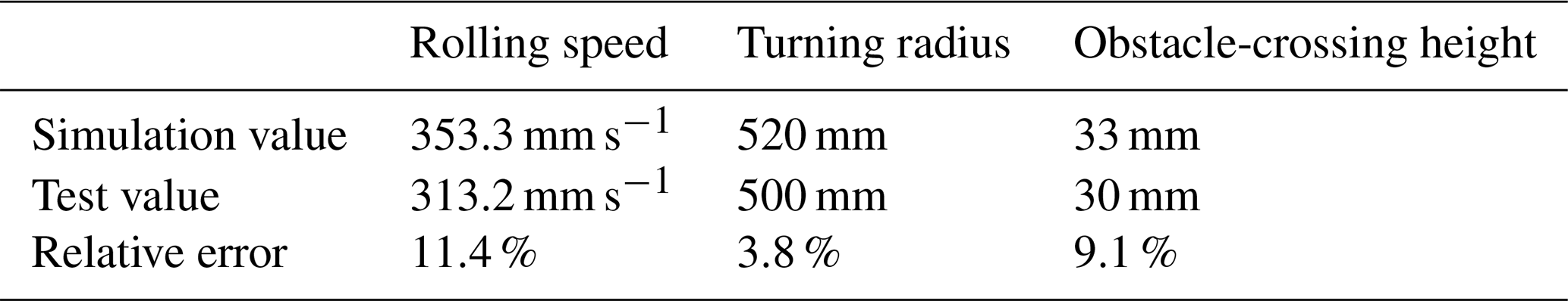
As can be seen from Table 2, although there is a certain relative error between the test values and the simulation values, considering the facts that the structure of the RPSR was simplified when solving the simulation values and that the energy losses caused by factors such as mechanical friction and transmission efficiency during the actual prototype's movement were not taken into account, the design scheme of the actual prototype based on the simulation model is feasible.
This study proposes an RPSR designed to overcome the inherent limitations of traditional fixed-shell spherical robots in terms of terrain adaptability. The core contribution lies in the successful design and validation of an innovative scheme that integrates a deployable polyhedral shell with a hybrid actuation system, thereby significantly enhancing mobility in complex environments.
The effectiveness of this reconfigurable design has been quantitatively verified through numerical simulations and physical prototype experiments. Its key innovation – the ability to dynamically adjust the shell radius – proved to be highly effective in obstacle-crossing tasks. Experimental results demonstrated that the prototype could expand its radius to traverse obstacles up to 30 mm in height, directly addressing the performance bottleneck of fixed-shell robots. Meanwhile, the hybrid pendulum–rotor actuation system enabled stable and reliable locomotion: the prototype achieved a maximum rolling speed of 313.2 mm s−1 in experiments, while simulations indicated a lateral deviation of less than 4.3 % during linear motion, confirming its motion stability.
Strong consistency between Adams simulation and experimental results further validated the reliability of the theoretical framework. Comparative analysis revealed that the relative errors of key performance indicators remained within acceptable limits: 11.4 % for rolling speed, 3.8 % for turning radius, and 9.1 % for obstacle-crossing height. These findings confirm the predictive accuracy of the Newton–Euler-based dynamic model and the feasibility of the mechanical design.
Nevertheless, the proposed model and prototype still exhibit certain limitations. From a theoretical perspective, the dynamic model relies on several idealized assumptions, such as non-slip ground contact and perfectly rigid shell behavior during obstacle traversal. While these assumptions simplify the analysis, they fail to fully account for energy losses caused by slippage or deformation. From a practical standpoint, the structural complexity of the multi-loop kinematic chains poses challenges to manufacturing precision and structural robustness. Furthermore, the energy efficiency of the hybrid actuation system, particularly the additional rotor, was not evaluated, leaving the endurance of the robot under extended operation as an open issue.
In summary, this work establishes a validated framework for a new class of adaptive spherical robots. By quantitatively demonstrating the advantages of structural reconfiguration, it provides both theoretical and practical foundations for future designs and shows broad application potential in exploration, inspection, and automation within unstructured environments. Future research should focus on incorporating non-ideal conditions into the dynamic model and optimizing the mechanical design to improve both energy efficiency and manufacturability.
All the code used in this article can be made available upon reasonable request. Please contact Kan Shi (kan.shi@hotmail.com) and Haidong Wang (3030903338@qq.com).
All the data used in this article can be made available upon reasonable request. Please contact Kan Shi (kan.shi@hotmail.com) and Haidong Wang (3030903338@qq.com).
KS and HDW proposed and developed the overall concept of the paper and conducted the mechanism design and analysis. HDW wrote the whole paper. DBZ and RW assisted in the prototype construction work.
The contact author has declared that none of the authors has any competing interests.
Publisher’s note: Copernicus Publications remains neutral with regard to jurisdictional claims made in the text, published maps, institutional affiliations, or any other geographical representation in this paper. While Copernicus Publications makes every effort to include appropriate place names, the final responsibility lies with the authors. Views expressed in the text are those of the authors and do not necessarily reflect the views of the publisher.
This paper was edited by Benliang Zhu and reviewed by two anonymous referees.
Armour, R. H. and Vincent, J. F. V.: Rolling in nature and robotics: a review, J. Bionic Eng., 3, 195–208, https://doi.org/10.1016/S1672-6529(07)60003-1, 2006.
Cai, J. G., Xu, Y. X., and Feng, J.: Kinematic analysis of Hoberman's linkages with the screw theory, Mech. Mach. Theory, 63, 28–34, https://doi.org/10.1016/j.mechmachtheory.2013.01.004, 2013.
Diouf, A., Belzile, B., Saad, M., and St-Onge, D.: Spherical rolling robots – design, modeling, and control: a systematic literature review, Robot. Auton. Syst., 175, 104657, https://doi.org/10.1016/j.robot.2024.104657, 2024.
Dwaracherla, V., Thakar, S., Vachhani, L., Gupta, A., Yadav, A., and Modi, S.: Motion planning for point-to-point navigation of spherical robot using position feedback, IEEE/ASME Trans. Mechatron., 24, 2416–2426, https://doi.org/10.1109/TMECH.2019.2934789, 2019.
Gu, Y., Zhang, X., Wei, G., and Chen, Y.: Sarrus-inspired deployable polyhedral mechanisms, Mech. Mach. Theory, 193, 105564, https://doi.org/10.1016/j.mechmachtheory.2023.105564, 2024.
Jing, C. and Zheng, J.: Stable walking of biped robot based on center of mass trajectory control, Open Phys., 18, 328–337, https://doi.org/10.1515/phys-2020-0148, 2020.
Li, R. M., Yao, Y. A., and Kong, X. W.: Reconfigurable deployable polyhedral mechanism based on extended parallelogram mechanism, Mech. Mach. Theory, 116, 467–480, https://doi.org/10.1016/j.mechmachtheory.2017.06.014, 2017.
Matei, L., Iliescu, M., Dumitru, I., Racila, M., Glencora-Maria, B., and Racila, L.: Reconfigurable/foldable overconstrained mechanism and its application, Appl. Sci., 12, 262, https://doi.org/10.3390/app12010262, 2022.
Meng, Q., Xie, F., Tang, R., and Liu, X. J.: Deployable polyhedral mechanisms with radially reciprocating motion based on novel basic units and an additive-then-subtractive design strategy, Mech. Mach. Theory, 181, 105174, https://doi.org/10.1016/j.mechmachtheory.2022.105174, 2023.
Müller, A.: Wohlhart's three-loop mechanism: an overconstrained and shaky linkage, in: Advances in Robot Kinematics 2020, edited by: Lenarčič, J. and Siciliano, B., Springer, Cham, 125–132, https://doi.org/10.1007/978-3-030-50975-0_16, 2021.
Sagsoz, I. H. and Eray, T.: Design and kinematics of mechanically coupled two identical spherical robots, J. Intell. Robot. Syst., 108, 12, https://doi.org/10.1007/s10846-023-01853-y, 2023.
Shiota, T. and Saitoh, T.: Overlapping edge unfoldings for convex regular-faced polyhedra, Theor. Comput. Sci., 1002, 114593, https://doi.org/10.1016/j.tcs.2024.114593, 2024.
Thoesen, A. and Marvi, H.: Planetary surface mobility and exploration: a review, Curr. Robot. Rep., 2, 239–249, https://doi.org/10.1007/s43154-021-00056-3, 2021.
Wang, L., Zhang, J. W., and Zhang, D.: A review on reconfigurable parallel mechanisms: design, analysis and challenge, Engineering, 47, 100–116, https://doi.org/10.1016/j.eng.2024.09.022, 2025.
Wei, G. W., Chen, Y., and Dai, J. S.: Synthesis, mobility, and multifurcation of deployable polyhedral mechanisms with radially reciprocating motion, J. Mech. Des., 136, 091003, https://doi.org/10.1115/1.4027638, 2014.
Wei, X. Z., Tian, Y. B., and Wen, S. S.: Design and locomotion analysis of a novel modular rolling robot, Mech. Mach. Theory, 133, 23–43, https://doi.org/10.1016/j.mechmachtheory.2018.11.004, 2019.
Yang, T., Li, P., Shi, Q., and Liu, Y.: Deployable polyhedral mechanisms with radially reciprocating motion based on non-crossing angulated structural element, Proc. IEEE RCAR 2021, 1294–1299, https://doi.org/10.1109/RCAR52367.2021.9517559, 2021.
Zhan, Q. and Li, W.: Research progress and development trend of spherical mobile robots, J. Mech. Eng., 55, 1–17, https://doi.org/10.3901/JME.2019.09.001, 2019.
Zhang, Y., Gu, Y., Chen, Y., Li, M., and Zhang, X.: One-DOF rigid and flat-foldable origami polyhedrons with slits, Acta Mech. Solida Sin., 36, 479–490, https://doi.org/10.1007/s10338-023-00404-0, 2023.
- Abstract
- Introduction
- Overall structural design of the robot
- Dynamic analysis of the robot's rolling characteristics
- Simulation of polyhedral spherical robot based on Adams
- Fabrication and experiment of the robot prototype
- Conclusion
- Code availability
- Data availability
- Author contributions
- Competing interests
- Disclaimer
- Review statement
- References