the Creative Commons Attribution 4.0 License.
the Creative Commons Attribution 4.0 License.
 | 11 Nov 2025
Design and analysis of parallel manipulators with 3 translational degrees of freedom used as an anti-balance perturbator, exactly constrained and overconstrained
Jacob P. Meijaard
Winfred Mugge
Volkert van der Wijk
The design of parallel manipulators with 3 translational degrees of freedom to deliver short-duration reactive inertial forces on the base is discussed. The intended application is a device that can apply perturbing forces on human limbs. The device, called an anti-balance perturbator, has to be mounted around the limb in a non-obtrusive way, to be lightweight with most mass attached to the moving platform, to have a large workspace with respect to the available space and to have a large bandwidth. Three designs are compared: an exactly constrained manipulator with three RUU legs, an overconstrained overactuated manipulator with four RUU legs and a manipulator with three overconstrained RRPaR legs. The designs contrast to common ones, because most mass is placed on the movable platform and because the base and the platform are almost in the same plane. A kinematic analysis addresses singularities and the sensitivity of the platform motion for clearance in the joints. Moreover, the compliance at the platform due to leg flexibility is determined. For these analyses, aggregate properties of the legs are used, which simplifies the analysis. Since the results show that the overconstrained manipulators are much less sensitive to clearance and much stiffer than the exactly constrained 3RUU manipulator, the design specifications can be more easily met. This makes the overconstrained designs preferable.
- Article
(7800 KB) - Full-text XML
- BibTeX
- EndNote


The present study arose from the need for a small device that can generate forces on limbs of the human body, in particular on the lower arm. The purpose of these forces is to identify the frequency-dependent dynamic stiffness under a range of everyday tasks without severely hampering the natural motion, as people can adjust joint stiffness by co-contraction of muscles and reflexive responses (Doemges and Rack, 1992a, b; Mugge et al., 2010). Short-duration applied forces can be used to study these reflex responses. Knowledge of human motor control and its adaptations is important for diagnostics and robots for rehabilitation and in domestic applications.
To estimate the dynamics and control of human motion, the perturbations can be forces or position changes, and they can be continuous or transient. The perturbations may differ in their frequency content and their amplitude or power spectrum and can be deterministic or random (Cathers et al., 1999; Mugge et al., 2007). The perturbations can be applied at various points in different directions (Trumbower et al., 2009; de Vlugt et al., 2006), and the device with which the perturbations are applied can have its own dynamic properties (Schouten et al., 2008). Furthermore, the way in which the subject is instructed can have a large influence on the results (Doemges and Rack, 1992a, b).
To allow tests with a more natural motion of the hand, we decided not to apply the forces externally but to use moving bodies to generate reaction forces due to accelerations; we call a device that generates this kind of force an anti-balance perturbator. The purpose is to apply dynamic forces on the support, which is in contrast to dynamically balanced devices intended not to generate these resultant shaking forces or shaking moments on the support (Berkof and Lowen, 1969; van der Wijk, 2014). Based on the same principle, a handheld device that uses a mechanism to generate a periodic force in one direction is described in Amemiya et al. (2007) and a device using air pressure to move a piston is described in Höppner et al. (2010). An alternative principle is to use the reaction force of an airjet (Xu et al., 1991; Belden et al., 2011; Gurocak et al., 2003), but such a device has the drawback of a high noise level and obtrusive tubing. Gyroscopic torque generators have been used to suppress tremor (Mertz, 2016) and to prevent falls (Lemus et al., 2017). Reaction wheel and control moment gyroscope torque generators have been developed to give haptic signals to the wearer (Amemiya and Gomi, 2013; Walker et al., 2016; Choinière and Gosselin, 2017).
The moving mass can be guided in several ways. One concept uses a straight or circular bearing, along which the mass glides. Another concept is to use a mechanism for the guidance. For generating forces in several directions, a mechanism with a parallel architecture or a serial architecture can be used. We choose a guiding mechanism with a parallel arrangement, that is, a parallel manipulator, because a compact design can be realized and a large fraction of the total mass can be placed on the moving platform. Putting most mass on the platform inverts conventional designs with most of the mass in the stationary base. In the present design, the base is not fixed but connected to the moving limb. Furthermore, the base and the platform are nearly in the same plane, and the base is smaller than the platform, which differs from the usual designs. An initial design has been built and tested (Koene, 2022; Koene et al., 2023).
Since a large workspace relative to the size of the device is required, the manipulator may encounter singularities. Singularities in mechanisms have been widely studied (Gosselin and Angeles, 1990; Zlatanov et al., 1998; Merlet, 2006). Here, singularities are analysed by considering the manipulator as a constrained mechanical system.
For small mechanisms, clearances in the joints can be relatively large, and their influence on the position and orientation of the moving platform is important to consider as it may worsen the performance. The influence of joint clearance on the kinematics of planar linkages was investigated by Kolhatkar and Yajnik (1970), who introduced massless clearance links. Tischler and Samuel (1999) studied the influence on spatial statically determinate mechanisms. All clearances were supposed to be independent, and a linearized analysis was made. A similar approach was reported by Innocenti (2002) for a given load on the end effector. This analysis procedure was extended for general loads by Parenti-Castelli and Venanzi (2005). Frisoli et al. (2011) maximized a quadratic pose error function. Clearances in overconstrained manipulators were studied by Meng et al. (2009). Wu et al. (2012) studied a planar parallel manipulator and included both tolerances and clearances; the results were experimentally validated. Ding and Wang (2021) considered planar systems in which the change in length of a link due to clearance was considered, while Ding et al. (2023) analysed spatial mechanisms with only displacement clearance in the joints. In the present study, a clearance analysis following these lines is proposed, which considers the combined clearance of legs and is applicable to overconstrained systems. A stiffness analysis is performed which considers leg stiffness as in Pashkevich et al. (2009) and Yang et al. (2018) and follows a method similar to the clearance analysis.
The main contributions of this article are, firstly, the application of parallel manipulators in the field of wearable perturbators used for applying forces to human limbs; secondly, the complete inversion of the usual design of the manipulators with most mass placed on the platform instead of the base; thirdly, the presentation of the singularity analysis in terms of constrained mechanical systems; and fourthly, the clearance analysis with aggregate properties of legs. These analyses show the feasibility of the proposed overconstrained designs for the application.
In Sect. 2, the kinematic design process is described that leads to the unusual characteristics of the manipulators. A procedure to analyse singularities is described, and simulations are made to show that the manipulators fulfil the requirements. Then, procedures to analyse the influence of clearance and to calculate the compliance, both of which depend on the position of the end effector, are presented, and comparisons of the exactly constrained and overconstrained designs are made.
In this section, the requirements are stated that aid the choice for the concept of a parallel mechanism. Then, an architecture is chosen. Based on the required workspace and the limitation of the design space, the dimensions and the configuration of the legs are chosen. A kinematic analysis is made, and three design variants are proposed.
2.1 Force and motion requirements
The actuation force requirements are extracted from the literature. In an experiment by Trumbower et al. (2009), perturbations on the hand were applied as random displacements with a flat power spectrum in the range of 0–5 Hz and with a standard deviation of 3 mm. The forces generated were in the range of 5–10 N. The same perturbations were used by Krutky et al. (2013), but a ramp-and-hold perturbation was also used in which a velocity of 400 mm s−1 was applied during 100 ms. Nashed et al. (2012, 2014) applied perturbations of 0.5–2.0 Nm at the elbow and shoulder joint. The duration was intended to excite reflexive responses, which occur 20–105 ms after the onset of the perturbation.
Based on these previous studies, a motion profile for applying a short-duration transient impulse intended for the design is chosen, as shown in Fig. 1. The moving body, called the platform or the end effector, is first placed in an eccentric position with respect to the base, fixed to the arm, with a relatively slow motion. Then, the platform is accelerated in a radial direction towards the central position, resulting in a shaking force of 7.0 N in the first 10 ms. After that, the platform is decelerated by one ninth of the initial acceleration during 90 ms, resulting in a shaking force of 0.78 N in the opposite direction. At the end of this deceleration period, the platform is at rest with respect to the base but with an eccentric position at the opposite side. It is assumed that the deceleration has little influence on the human response, as the resulting shaking force is smaller than the total weight of the device, which is about 1 N. The whole manoeuvre is executed within 100 ms. The acceleration profile can be smoothed to reduce the required bandwidth. Other types of force profile can be applied as long as they can be realized with the same device.
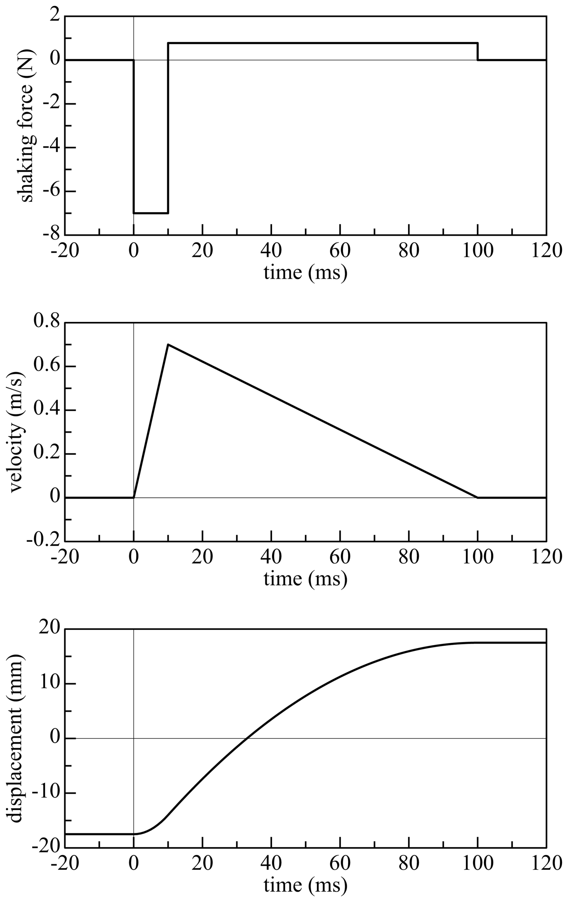
Figure 1Shaking force profile, equal to minus the mass times acceleration (top panel), velocity profile (middle panel) and displacement profile (bottom panel) for a moving mass of 0.10 kg.
There is a trade-off between the total mass and the range of motion of the moving platform: a larger mass of the moving platform results in lower accelerations and a smaller range of motion and vice versa. Figure 1 shows the force, velocity and displacement profiles for a mass of 0.10 kg, which yields a maximum acceleration of 70 m s−2, a maximum velocity of 0.70 m s−1 and a total displacement of 35 mm. It is assumed that the base is fixed. As inertial forces depend on the absolute, not the relative, accelerations, a compensation for the motion of the base can be made by increasing either the mass or the range of motion: increasing the mass is the more convenient option.
Although the shaking forces are intended and useful, shaking moments have to be limited. The length scale defined by the maximum shaking moment divided by the maximum shaking force is a good measure, which has to be below a few millimetres, as indicated by a pilot experiment.
Whereas the moving mass has to be relatively high, the mass of the non-moving parts needs to be reduced as much as possible to make the total weight of the device as small as possible for a given value of the moving mass. Limiting the total weight reduces the repercussion of wearing the device on the natural motion of the limb between perturbations.
2.2 Basic architecture
The requirement that the shaking moments should be small can best be fulfilled by a mechanism that only allows a translational motion of a platform in the same plane as the base. The relatively large accelerations make a parallel mechanism preferable to a serial mechanism, because it is stiffer and the actuators act in parallel. To generate forces in arbitrary directions, a translation in three directions is needed. Even if a 2-D motion could be sufficient, it has some advantages to have a 3-D motion to avoid, for instance, points of singularity or collisions of links with each other or with the boundaries of the available space. The motion requirements in a plane perpendicular to the limb are mandatory, but the motion requirements for the direction along the axis of the limb can be relaxed if it is difficult to fulfil them.
Several aspects of the design and analysis of parallel robots and examples of realizations are described by Merlet (2006). A well-known example of a mechanism for translational motion is the Delta robot (Clavel, 1991). This robot in its usual form contains spherical joints, which have a limited range of motion and are therefore better avoided in compact designs. Prismatic joints can have a large range of motion, but guidances or screw spindles may stick out when actuated and they may have a relatively large size. Currently available more compact versions based on flexure mechanisms are not stiff enough. Revolute joints are therefore preferred in the present design.
Kong and Gosselin (2007) give a large number of parallel mechanisms that generate a desired type of motion. For a translation in three directions, they give three essentially different types of mechanism with three legs with five revolute joints each. The leg configurations can be classified as ŔŔ, ŔŔŔ and ŔŔŔ, where R denotes a revolute joint and accents of the same kind denote parallel rotation axes. Two additional types are found by reversing the order of the two last-mentioned types. All types can be found from a cyclic permutation of axes of any one of them. Each leg constrains an instantaneous rotation in a direction orthogonal to the two directions of the axes of the revolute joints. If non-parallel joint axes are perpendicular to each other, pairs of non-parallel adjacent rotation axes can be combined into universal joints and the three types of mechanism can be reduced to URU, RUU and RRUR, where U denotes a universal joint. The last one would require three links instead of two and is therefore not studied any further. Examples of the first and second configurations are shown in Fig. 2. The RUU configuration has the advantage over the URU configuration that the out-of-plane motion of the left view can still take place in a nearly folded pose. The RUU configuration is chosen, although it is asymmetric.
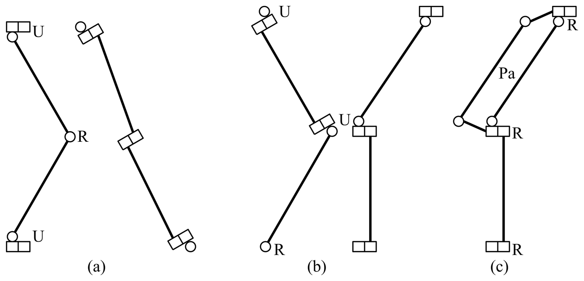
Figure 2Schematic drawings of the URU leg (a) and the RUU leg (b) in front and side views, where revolute joints are represented by tin cans (Schwab and Meijaard, 2006); (c) shows the coupling of the two hinge rotations of the RUU leg, resulting in an RRPaR leg.
The manipulator can be actuated at joints in the legs, but the actuation can also be accomplished independently of the guiding, for instance, by cables. Because cables can only transmit tensile forces, at least four cables are needed for a translating platform if it has to be possible to apply forces in arbitrary directions on the platform. Other kinds of independent actuation can be employed with the same architecture.
There is still a large freedom in the way the leg can be arranged. It is chosen to place the revolute joint at the base and a universal joint on the moving platform, because more space is available for the larger universal joint and it moves mass to the platform. The mechanism will then be driven at the universal joint if no independent form of actuation is used. In a nominal central position, the links are in an axial–radial plane, that is, in a plane perpendicular to the plane of the main motion of the moving platform. An exactly constrained mechanism can be obtained with three legs, denoted by 3RUU. An overconstrained design may have some advantages, such as increased stiffness, a reduction in the influence of clearance and the avoidance of actuator singularities, so an overconstrained and overactuated design with four legs, denoted by 4RUU, and a design with three legs in which the two revolute joints with opposite rotation angles are coupled by a parallelogram, as shown in Fig. 2c (denoted by 3RRPaR), will also be considered. The four hinges with axes out of the plane are arranged at the vertices of a parallelogram, as in a four-bar mechanism with equal opposite link lengths. The parallelogram adds four constraints, three of which are internal to the four-bar linkage, and one constrains another rotation of the moving platform: all rotations about axes perpendicular to the axis of the revolute joint are constrained. Note that this leg is similar to the legs of a Delta robot, with the spherical joints replaced by revolute joints.
2.3 Choice of the main dimensions
For the moving mass, a value of 0.10 kg is chosen. On the one hand, a smaller mass would require a larger range of motion, and on the other hand, a larger mass would impede the natural motion of the arm of a wearer. Giving a size of the moving platform that just fits over the hand, the chosen value for the mass seems to be a reasonably good compromise and with it the motion and force profile as shown in Fig. 1 can be used. If motion in any direction is required, the workspace is a ball with a radius rw=17.5 mm. For a planar motion, the workspace is a disc with the same radius. This planar disc is used for an initial dimensioning.
The outer shape of the cross-section of the arm with the strap is approximated by an oblong shape, the outline of a stadium, that is, a rectangular central part with two circular semi-discs at two opposite ends, as shown in Fig. 3. The inner shape of the moving platform is also a stadium, which is a distance da apart from the strap. The legs are constructed in the space between the strap (the base) and the moving ring, with the joint axes at the connections tangent to the stadiums. The strap may never be crossed by any part of the legs, but the ring may be crossed if some holes are made in it to let the links pass through. A choice of da=0.025 m appears to be a good initial guess, as it leaves 7.5 mm of space for the joints at the extreme positions. On the basis of a typical size of a wrist, the radius of the semicircular parts of the strap is chosen as rs=0.030 m, and the central rectangular part is 2dc=0.020 m wide. Variants with different sizes can be easily derived from the current design.
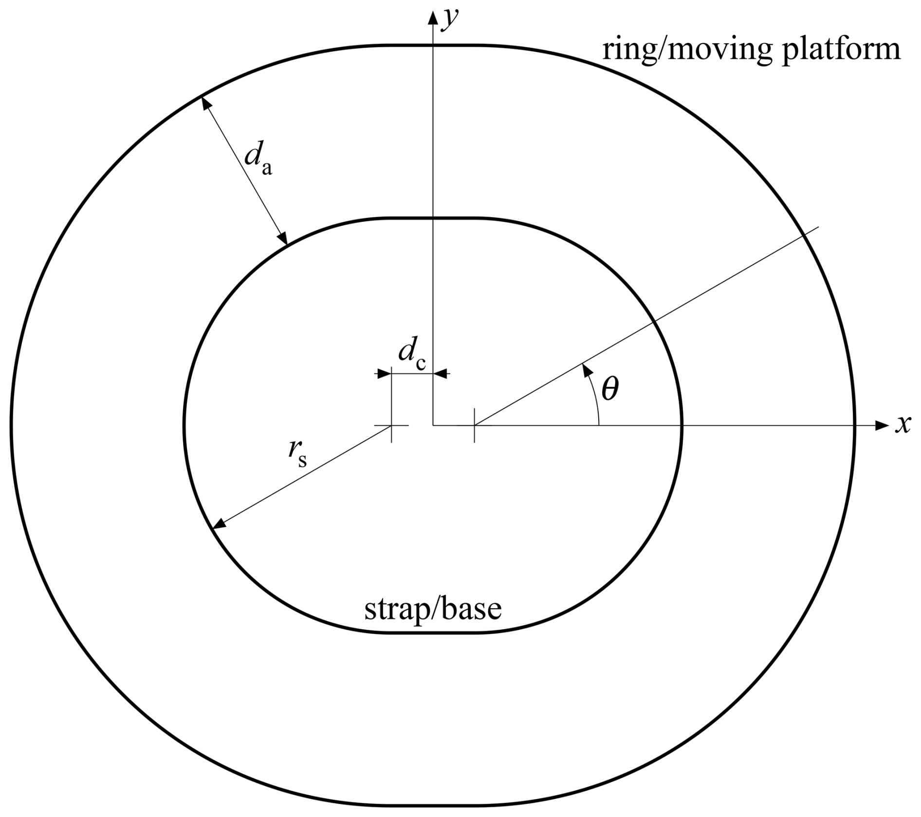
Figure 3The outer shape of the strap for mounting on the limb, the inner shape of the moving ring and the space between them.
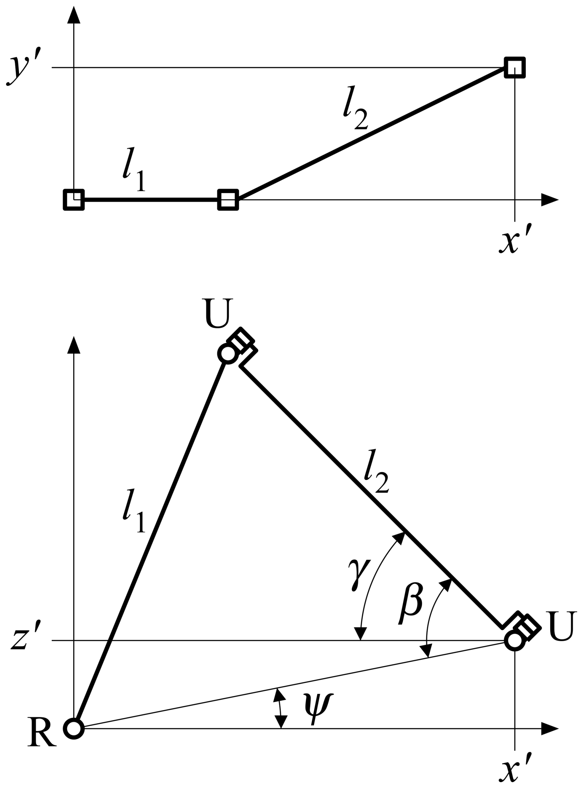
Figure 4 shows the leg mechanism in the plane, where the x′ axis is in the radial direction, the z′ axis is in the axial direction and the y′ axis is in the circumferential direction. The revolute joints are numbered from the base (strap) to the platform (ring), so the first joint is located at the base and has its axis in the local y′ direction, the second and third joints form the intermediate universal joint, and the fourth and fifth joints form the universal joint at the platform. The first link is located between the first and the second joint and has a length of l1. The second link is located between the third and the fourth joint and has a length of l2. In the design, the link lengths are set to be equal, and the first joint may be offset by a distance of z0 from the main plane of motion. Equal link lengths have the advantage that the mechanism can fold up, and a small overall size (footprint) for a given workspace is realized. To stay away from the singular fully folded and fully extended poses, the angle between the two links is required to vary between a minimum angle αmin and a maximum angle αmax, which are supplementary. For a given value of z0, the relations
hold according to the cosine rule, from which follows, with ,
where is the distance of the origin of the leg coordinate system to the centre of the workspace. If l1=l2, then . For da=25 mm, z0=0 mm, l1=21.58 mm; if z0=10 mm instead, l1=22.71 mm. A value of l1=23 mm appears to be a good value, since small values of the angle enclosed by the links are not as detrimental as large values, which follows from the inverse kinematics detailed in Sect. 2.4; for z0=0 mm, the extreme angles for the whole workspace are 18.77 and 135.01° and for z0=10 mm, these are 23.65 and 143.93°.
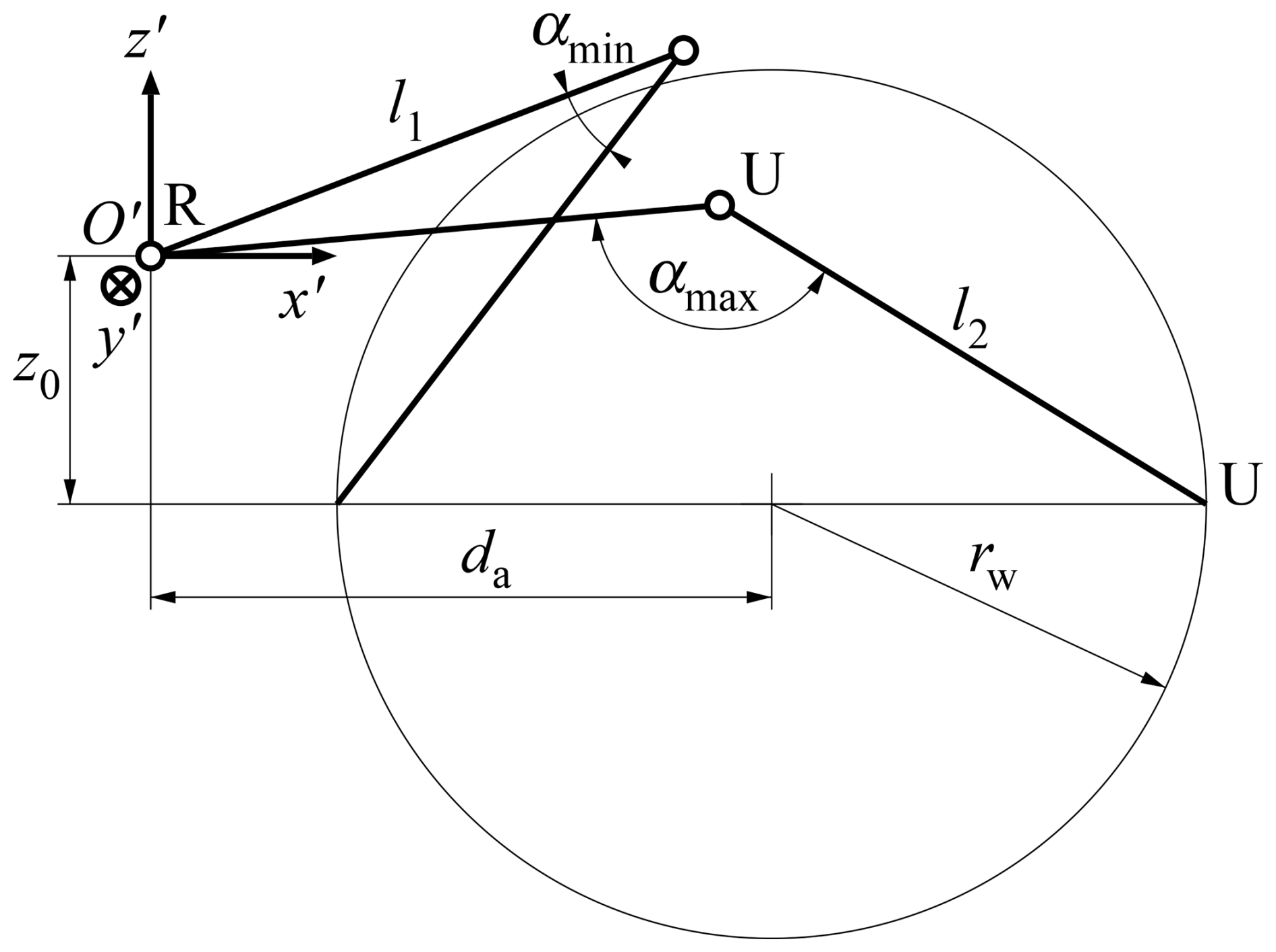
Figure 4Diagram to determine the dimensions of a leg with the links in the local plane, with two extreme positions of the leg shown.
2.4 Inverse and forward kinematics
For the inverse and forward kinematic analysis, a local right-handed coordinate system is introduced for each leg, with the origin O′ at the first joint and the axes as in Fig. 4. In the inverse kinematics, the position of the end effector (the platform) is given, for which the angles at the actuators need to be determined and similarly for the velocities and accelerations. For the present mechanism, the inverse kinematics can be found for each leg separately, because the equations are decoupled. The position of the moving platform in the coordinate system fixed to the base determines the position of the attachment point of a leg to the platform in the local coordinate system as
where θ is the angle that the x′ axis makes with the x axis, as shown in Fig. 3.
The angle γ of the fifth joint, which is actuated, is found from Fig. 5. The projected length of l2 is , and the cosine rule yields
This angle is measured from the line through the attachment point parallel to the x′ axis. The angular velocity and the angular acceleration of the actuated angle can be found by differentiating the above expression, where, besides the position, the velocity and acceleration of the platform are prescribed.
In the forward kinematic analysis, the angles, angular velocities and angular accelerations of the actuators are prescribed. The position and orientation of the platform, with velocities and acceleration, have to be determined. For parallel manipulators, this problem is harder than the inverse kinematics, and many solutions may be found. If only solutions in which the platform does not rotate are sought and the legs are actuated at the joints at the base, the position of the platform can be obtained from the problem of finding the intersection of three spheres, a standard geometric problem. Two spheres define a circle as their intersection together with the plane in which this circle is positioned. The intersection of this plane with the third sphere defines a second circle in this plane. There are, in general, two intersection points of these circles, which give two solutions. For the case where the legs are actuated at the joints of the platform, an analytical solution is complex, so a numerical solution procedure is used.
2.5 Singularities
Singularities can be investigated by studying the constrained mechanical system. The configuration of the mechanism is described by the coordinates x, which can contain the position and orientation variables of bodies but also the joint coordinates, and are not independent. With the m+n coordinates x of the mechanism, the m+r constraints can be formulated as C(x)=0, where n is the number of degrees of freedom, m is the number of independent constraints and r is the number of essential overconstraints. By differentiating the constraints at a feasible configuration, the constraints on the velocities are obtained, where a subscript comma followed by variables denotes partial derivatives with respect to these variables. The rank of C,x is at most m, and configurations at which this rank becomes smaller than m are intrinsic singularities of the mechanism at which some additional constraints besides the r overconstraints on the velocities become dependent and the instantaneous number of degrees of freedom increases. For the proposed design, this happens when the directions of constrained rotation – that is, the directions perpendicular to the axes of the revolute joints of a leg – become dependent (i.e. they are all parallel to a plane), and an infinitesimal rotation of the platform about an axis perpendicular to this plane becomes possible. In exactly constrained designs, these singularities typically occur during motion over an extended range, but for overconstrained designs, these can be avoided.
Other types of singularity can occur, which are related to the way the mechanism is used, that is, the intended motion of the platform and the way the mechanism is actuated. If n independent variables xd are chosen and the others xc are dependent, the velocity constraint equation can be partitioned as
This equation can be solved for the dependent velocities if has rank m and r equations are dependent. In the inverse kinematics, the coordinates describing the motion of the platform are the independent coordinates and the others, in particular the angles of the actuators, are dependent. From the calculation procedure above, singularities can occur if the angle β in Fig. 5 becomes zero or a stretched angle and also if , which correspond to points on the boundary of the reachable displacements for the platform. By restricting the size of the workspace, the manipulator is never close to this boundary by design. A second kind of singularity can occur in the forward kinematics where actuator angles are chosen as the independent coordinates. A motion of the mechanism becomes possible with zero velocities of the actuators, and the actuator velocities cannot be chosen independently: the constraints imposed by fixing the actuators become dependent. This singularity occurs if the lines of constraint imposed by the legs are all parallel to a plane. The line of constraint in the proposed leg corresponds to the direction of the line of intersection of the plane through the first link and the axes of the first and second joints and the plane of the second link and the axes of the third and fourth joints; in the reference configuration, this is the direction of the first link. In an overactuated mechanism, the independent actuator motions can be chosen in different ways, which makes it possible to avoid singularities by choosing a different set of independent coordinates.
2.6 Design proposals
Three designs are considered in more detail to make a comparison. The first design has three legs, as shown in Fig. 6, which makes the mechanism exactly constrained and fully actuated. The legs are placed at angles of 120°, parallel to the directions θ=0°, θ=120° and θ=240° (see Fig. 3), but there is only one symmetry because of the oblong shape of the base and the platform. The second design has four legs, as shown in Fig. 7. The additional leg makes the mechanism overconstrained and overactuated if all four legs are driven by a motor. The four legs are placed at angles of 90°, parallel to the directions θ=0°, θ=90°, θ=180° and θ=270°, which gives a double symmetry. All legs are placed in the same way, with the intermediate joints having positive z coordinates in the central position. The dimensions are the same as given above, with z0=0. A third design has the same kinematics as the first design, but the three legs are overconstrained by coupling the third and fourth revolute joints by a parallelogram mechanism (see Fig. 2c), which forces their rotation angles to have the same magnitude but opposite directions. The additional bar of the parallelogram is placed parallel to the second link at an offset out of the plane of the leg in the nominal configuration. Each leg constrains rotations of the platform orthogonal to the free rotation about the direction of the three revolute joints with parallel axes. In addition, each parallelogram introduces three internal overconstraints. This design is fully actuated as the first design is.
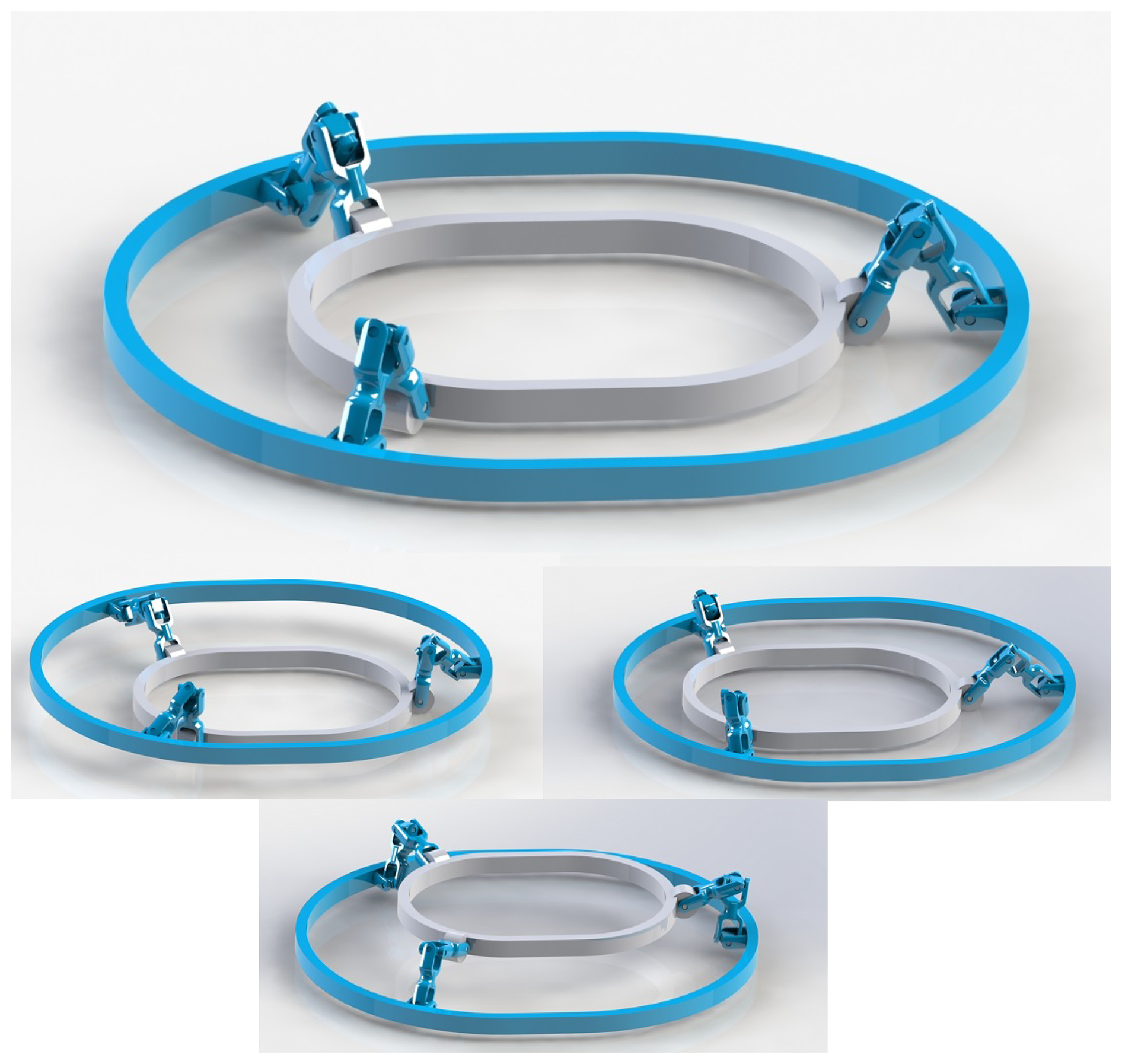
Figure 6Embodiment of the exactly constrained parallel manipulator with three legs: central position and three displaced positions.
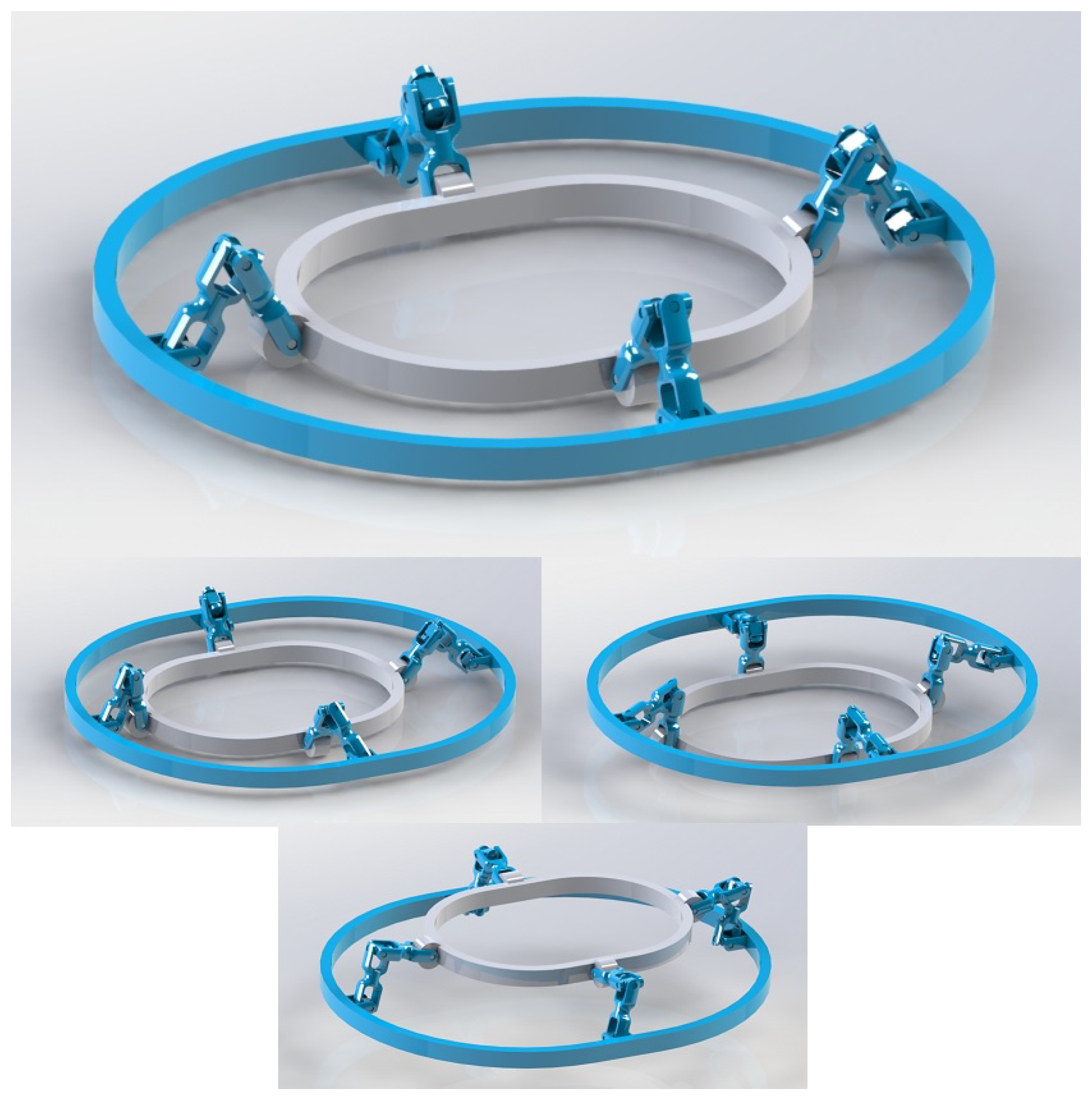
Figure 7Embodiment of the overconstrained parallel manipulator with four legs: central position and three displaced positions.
The mass of the platform is taken as 0.090 kg, the links have a mass per unit of length of 0.034 kg m−1 and the universal joints have a mass of 0.0018 kg. The total moving mass of the exactly constrained design is therefore 0.105492 kg, the total moving mass of the overconstrained design with four legs is 0.110656 kg and the design with overconstrained legs has a moving mass of 0.107838 kg. As these masses are all similar, the results can be directly compared.
Simulations are needed to evaluate the shaking forces and shaking moments as a check of the performance. Also, the range of relative rotations of the hinges and the transmitted forces and moments have to be determined for the design of the hinges and the links. For this purpose, a multi-body dynamics model has been developed for the program SPACAR (Jonker and Meijaard, 1990). The fixed base and the moving platform are modelled with rigid beam elements. Also, the links of the legs and the connecting elements between points are modelled with rigid beam elements. The revolute joints in the legs are modelled with ideal hinge elements. From the known displacement profile of the platform, the angles of the actuated hinges are determined, and three of them are applied as given prescribed deformations of three of the actuated hinges. The fourth actuated hinge, if present, is given a constant input moment or is left unactuated. The motion is simulated, which gives the relative rotation angles of the revolute joints and the reaction forces at the ground and in the links and the actuation moments.
Figure 8 shows the resulting shaking forces for the exactly constrained design with three legs and a direction of motion of θ=20°. There are some deviations from the intended force profile with shaking forces of −6.58, −2.39 and 0 N in the x, y and z directions, respectively, during the initial force pulse, which are due to the finite mass of the links and the joints, but the results are acceptable for the foreseen application. The maximum shaking moment is 0.015 Nm, corresponding to a moment arm of 2.2 mm for a force of 7 N, which is sufficiently small. The direction of the shaking moments is approximately perpendicular to the motion direction and in the xy plane. It is caused by the mass of the legs and contains pronounced velocity-dependent terms.

Figure 8Shaking forces for the exactly constrained three-legged design with a motion direction of θ=20° in the x direction (fully drawn), the y direction (dashed) and the z direction (dashed-dotted). The intended force pulse starts at 0 s and ends at 0.01 s.
Figure 9 shows the corresponding angles of the hinges. At the central position, the angles have their nominal values and the lines intersect. The maximum angles at the base (dashed lines) are about 90°, which is on the boundary of what is acceptable; this could be improved by choosing a small positive value for z0. The other angles stay within their allowed ranges.
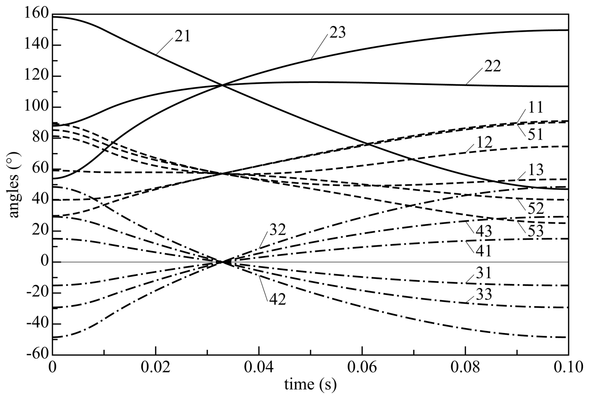
Figure 9Angles of the hinges for a motion direction of θ=20°, with three groups: the second angles (fully drawn), the first and last angles (dashed) and the opposite pairs of angles of the other hinges (dashed-dotted). Label ij denotes the angle of the ith joint of the jth leg.
Calculations for the shaking forces and joint angles have been made for a range of motion directions for both idealized designs to evaluate the overall performance. These give similar results.
In this section, the influence of clearance in the joints on the orientations and the position of the platform is investigated and the compliance is calculated.
4.1 Clearance analysis
Each revolute joint inevitably has some clearance or a large friction. The radial clearance gives rise to a possible change in the relative orientation of the axle with respect to the bushing. This error can be expressed as an angle. For a radial clearance of 0.005 mm in the proposed design with bearing lengths of about 6 mm, this angle is rad. As each leg has five revolute joints, and the direction of the rotation constraint of a leg is always perpendicular to the axes of the joints, the clearance angle can build up to c=0.0075 rad (0.43°) in the direction of the common normal to the axes of the joints. Errors in the displacements due to clearance can be compensated by the actuator feedback control.
For the design with three legs, an advantageous configuration where the directions of the clearance for the legs are perpendicular to each other results in a clearance of the platform, which is a factor of (the length of the sum of the three orthogonal unit vectors) higher than the clearance of a single leg, that is, 0.013 rad (0.74°). For a general configuration with normals directed along unit vectors n1, n2 and n3, a small rotation angle of the platform ϕp gives the angles of the legs in the directions of the constrained rotations
The absolute value of each of the leg rotations ϕi ( has to be smaller than, or equal to, the leg clearance ci. The maximum platform rotation can be found by checking the vertices of the domain and selecting the highest value; that is, the platform rotation is calculated from
where only half of all combinations of signs have to be checked because of the symmetry and the maximum Euclidean norm of ϕp is determined.
It is found that the maximum clearance occurs at the boundary of the workspace, so only a circle with a diameter of 35 mm in the xy plane is investigated. For the proposed configuration with three legs, Fig. 10 shows the amplification factors for the clearance, that is, the ratio of the clearance of the platform to the clearance of a single leg. The maximum rotation angle of the platform is nearly 19 times as high as the clearance of each leg, that is, about 0.14 rad (8°), which is unacceptably high. The high amplification is due to the fact that the configuration comes close to an essential singularity.
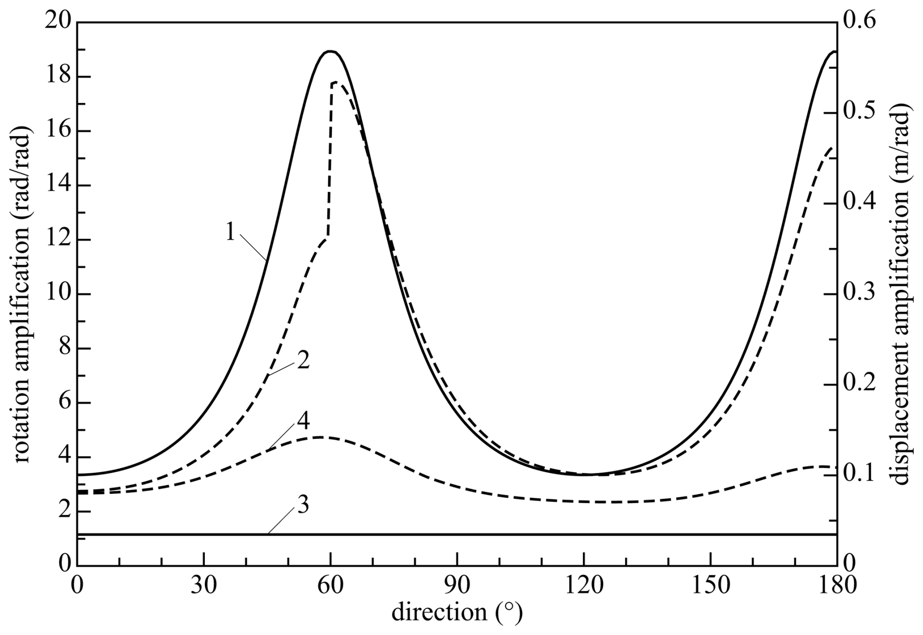
Figure 10Clearance amplification factors as functions of the direction angle θ at a radial displacement of 17.5 mm for the three-legged manipulator; amplification factor for the rotations (fully drawn) and for the displacements (dashed). Lines 1 and 2 are for the exactly constrained manipulator, and lines 3 and 4 are for the manipulator with overconstrained legs. Because of the symmetry, the range of angles is restricted to 0–180°.
If a feedback control on the displacements is available, the clearance in the displacements is determined by the properties of the control system. In commonly applied feed-forward control, the actuators have a prescribed angle. The clearance in displacement can then be determined by considering the displacements in the respective constraint directions of the legs due to the rotational clearance, where it is noted that each hinge takes up one fifth of the total rotation. With the displacement clearance of the platform up, the vectors from the centre of the platform to the fifth joints of the legs ri, the vectors in the constraint directions for fixed actuators lci (as defined in Sect. 2.5) and the vectors along the first and second links l1i and l2i, we have the relation for each leg that the displacement of the point of the fifth joint in the constraint direction equals
The first link of each leg suffers a clearance rotation equal to one fifth of the clearance rotation of the platform, and the third link suffers a clearance rotation that is three fifths of the platform clearance rotation. This leads to the equations
Solving this system of equations gives the displacement clearance of the platform for the maximum rotation clearance. The maximum displacement clearance may be larger for other clearance rotations of the platform, but the value of the displacement clearance for the maximum rotation angle of the platform gives a good indication. For the example with three legs, the magnitude of the displacement amplification, that is, the displacement clearance divided by the rotation clearance of a leg, for the maximum rotation of the platform is also shown in Fig. 10. The maximum displacement amplification is about 0.54 m rad−1, which corresponds to about 4 mm of clearance. The results for the clearance for the three-legged manipulator are more than 20 % of the desired motion range and are unacceptably high.
For the design with four legs, there is an additional normal vector n4 with angle ϕ4. For the case of free actuators,
Only three of the four constraints are normally active for this case; checking the vertices of the domain gives the combination of active constraints which yields the largest rotation of the platform. The magnitude of this rotation angle as a function of the direction at a platform displacement of 17.5 mm is shown in Fig. 11 as an amplification factor; the maximum value of this factor is 2.67, corresponding to a rotation angle of 0.020 rad (1.15°).
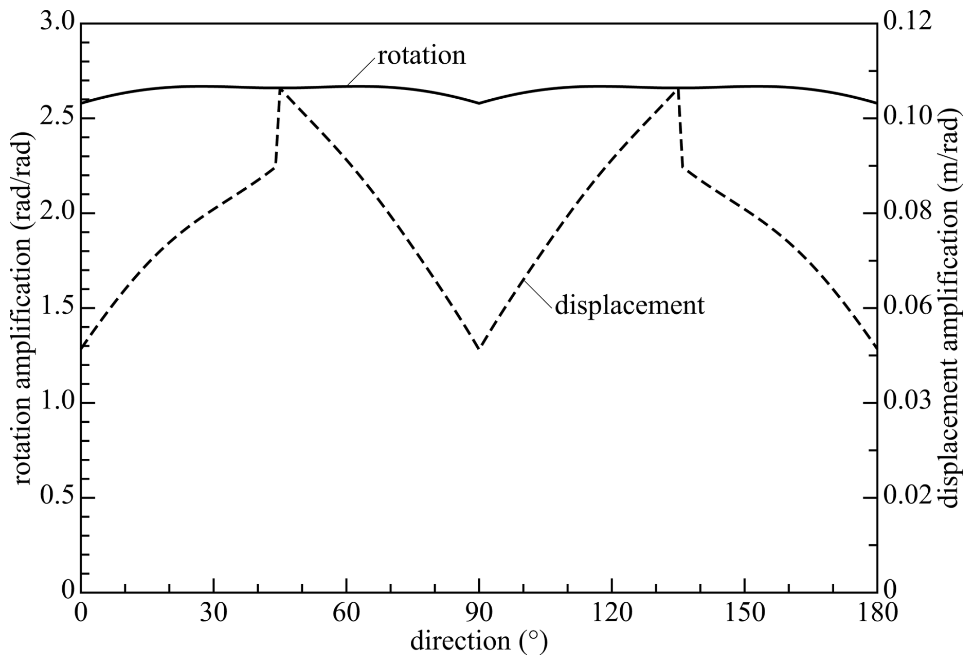
Figure 11Clearance amplification factors as functions of the direction angle θ at a radial displacement of 17.5 mm for the four-legged manipulator; amplification factor for the rotations (fully drawn) and for the displacements with fixed actuators (dashed).
For the case with fixed actuators, the additional leg introduces a constraint on the rotation besides constraints on the displacement of the platform. There are now four potential equalities of the type of Eq. (9):
In a simplified analysis to determine an upper bound of the displacement clearance, only the three equalities of Eq. (11) for the legs with active bounds of Eq. (10) for the determination of the largest rotational clearance are considered. This means that the amplification factors for the rotation are the same as for the case with free actuators. The amplification factor for the displacement clearance is about 0.106 m rad−1, which corresponds to about 0.80 mm of clearance. Figure 11 shows the amplification factors as functions of the orientation angle θ.
In the design with three overconstrained legs, the constraints imposed on the rotations are independent of the position of the platform. If the unit vector in the direction of the first revolute joint of leg i is denoted by ei and the 3×3 identity matrix by I, and it is assumed that the clearance perpendicular to ei is isotropic, this leg imposes the constraint on the rotation given by
which is a solid circular cylinder with its axis along ei. As all three unit vectors ei are in the xy plane and the angles between the legs are 120°, the maximum rotation occurs at
so the amplification factor is . This is the ratio of the distance between opposite corners and the distance of opposite sides of a regular hexagon, which is the intersection of the three solid circular cylinders and the plane z=0.
The displacement of the platform due to the clearance if the actuators are fixed is determined by Eq. (9) for the extreme platform rotations. This displacement depends on the position of the platform and is shown in Fig. 10. The maximum displacement amplification ratio is about 0.142 m rad−1, which corresponds to a displacement of about 1.1 mm.
The adding of a fourth leg reduces the influence of clearance by a factor of 6 to 7. This value can be accepted for the application envisioned. The design could be modified to reduce the individual clearances of the joints by making them larger or using tighter tolerances. The use of three overconstrained legs gives even better results for the clearance in rotations, but the displacement clearance is only reduced by a factor of 4; still, this makes this last design feasible.
As a validation, the method is applied to the planar system described in Wu et al. (2012). The results are in agreement with their calculations and experimental approach. The current method is simpler, as only four cases need be considered.
4.2 Compliance analysis
If k is the rotational stiffness value of each leg along the line ni, where this value is assumed to be independent of the configuration of the legs, each leg gives a contribution to the rotational stiffness matrix of . The actuator stiffness, which is usually lower than the support stiffness in the constrained directions, is neglected. The stiffness matrices K3 for rotations for the three-legged exactly constrained manipulator and K4 for the four-legged manipulator, which relate the torque on the platform to its rotations, can be found by adding the contributions of the legs, which act in parallel, as
when the actuated joints are assumed to be free. The maximum compliance is the largest eigenvector of the inverse of the stiffness matrix, which is equal to one over the smallest eigenvector of the stiffness matrix. Figure 12 shows the two compliances as factors relative to . The maximum compliance factor for the three-legged manipulator is about 178, whereas the maximum of this factor for the four-legged manipulator is about 2.74. This shows that the addition of a leg reduces the maximum compliance considerably. The manipulator with three overconstrained legs has a constant stiffness matrix if the stiffness of each leg is considered to be isotropic and independent of its configuration. Each leg then gives a contribution to the stiffness matrix of , which gives the stiffness matrix
so the compliance is multiplied by 0.67. This shows that this last design has an even smaller compliance.
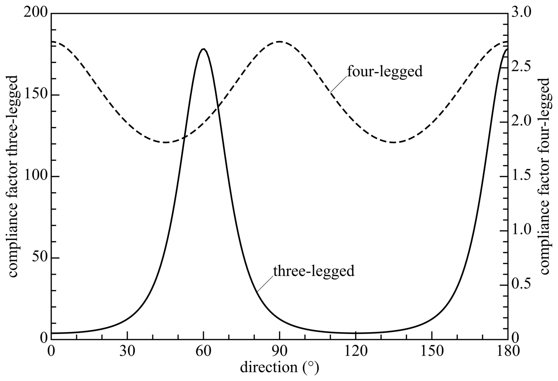
Figure 12Compliance amplification factors as functions of the direction angle θ at a radial displacement of 17.5 mm for the three-legged manipulator (fully drawn, left scale) and for the four-legged manipulator (dashed, right scale).
Internal stresses in overconstrained mechanisms due to manufacturing tolerances can have an influence on the stiffness if it is close to the buckling load (Meijaard et al., 2010; Klimchik et al., 2014). This may lead to a loss of stiffness for overconstrained mechanisms. For the current designs, buckling is unlikely, because the links are mainly loaded by moments and the deflections are small, so the internal stresses can be neglected.
This article has shown a new approach to the design of parallel manipulators to be used as an anti-balance perturbator. On the foundation of the requirements, a basic parallel architecture is chosen, kinematic dimensions are based on the required range of motion, inverse and forward kinematics are analysed and singularities are characterized. In the proposed designs, the actuators are placed on the moving platform and not on the stationary base, because the added mass fulfils a useful function, which is in contrast to the usual practice. The designs can be applied as a perturbator for applying force pulses on a human limb, but the manipulator can also be used in unrelated general applications.
A simple method of analysing the clearance has been shown. An exactly constrained fully actuated design with three legs, an overconstrained overactuated design with four legs and a design with three overconstrained legs have been compared. It has been revealed that the overconstrained designs are much less influenced by the clearance (a factor of 4 to 10) and the compliance (a factor of 65–267). The addition of a leg or the overconstraining of the legs leads to the avoidance of nearly dependent constraints and a better condition of the stiffness matrix near the boundary of the workspace. The three-legged exactly constrained manipulator is infeasible near the boundaries of the whole workspace, whereas the overconstrained versions can fulfil the specifications. On the other hand, an overactuated design is more difficult to control; a collocated control scheme is envisaged. Furthermore, the design of overconstrained legs with a parallelogram is more complicated.
Some experiments on a closely related design based on an inverted Delta manipulator have been made (Koene, 2022; Koene et al., 2023), which confirmed the superiority of an overconstrained four-legged manipulator. However, this design showed some shortcomings, especially in the control of the actuators. Therefore it is planned to develop and build an improved prototype that can be actually used in experiments on human subjects.
The SPACAR code is available at https://www.spacar.nl/download/2017/spacar2017.zip (last access: 4 November 2025).
All essential data are included in the text.
JPM did the analysis and the drafting and revising of the article. WM initiated, supervised and managed the project and contributed to the final version of the article. VvdW initiated, supervised and managed the project, conceived the principles of the mechanisms and contributed to the final version of the article.
The contact author has declared that none of the authors has any competing interests.
Publisher’s note: Copernicus Publications remains neutral with regard to jurisdictional claims made in the text, published maps, institutional affiliations, or any other geographical representation in this paper. While Copernicus Publications makes every effort to include appropriate place names, the final responsibility lies with the authors. Views expressed in the text are those of the authors and do not necessarily reflect the views of the publisher.
This paper was edited by Zi Bin and reviewed by Qasim Atiyah and four anonymous referees.
Amemiya, T. and Gomi, H.: Directional torque perception with brief, asymmetric net rotation of a flywheel, IEEE Trans. Haptics, 6, 370–375, https://doi.org/10.1109/TOH.2012.38, 2013. a
Amemiya, T., Kawabuchi, I., Ando, H., and Maeda, T.: Double-layer slider-crank mechanism to generate pulling or pushing sensation without an external ground, in: Proceedings of the 2007 IEEE/RSJ International Conference on Intelligent Robots and Systems, Piscataway NJ, San Diego CA, 29 October–2 November 2007, IEEE, 2101–2106, https://doi.org/10.1109/IROS.2007.4399211, 2007. a
Belden, J., Staats, W. L., Mazumdar, A., and Hunter, I. W.: A portable air jet actuator device for mechanical system identification, Rev. Sci. Instrum., 82, 035106, https://doi.org/10.1063/1.3562894, 2011. a
Berkof, R. S. and Lowen, G. G.: A new method for complete force balancing simple linkages, ASME J. Eng. Ind., 91, 21–26, https://doi.org/10.1115/1.3591524, 1969. a
Cathers, I., O'Dwyer, N., and Neilson, P.: Dependence of stretch reflexes on amplitude and bandwidth of stretch in human wrist muscle, Exp. Brain Res., 278–287, https://doi.org/10.1007/s002210050898, 1999. a
Choinière, J.-P. and Gosselin, C.: Development and experimental validation of a haptic compass based on asymmetric torque stimuli, IEEE Trans. Haptics, 10, 29–39, https://doi.org/10.1109/TOH.2016.2580144, 2017. a
Clavel, R.: Conception d'un robot parallèle rapide à 4 degrés de liberté, PhD thesis, École Polytechnique Féderale de Lausanne, Lausanne, https://doi.org/10.5075/epfl-thesis-925, 1991. a
de Vlugt, E., Schouten, A. C., and van der Helm, F. C. T.: Quantification of intrinsic and reflexive properties during multijoint arm posture, J. Neurosci. Methods, 155, 328–349, https://doi.org/10.1016/j.jneumeth.2006.01.022, 2006. a
Ding, J. and Wang, C.: Error modeling and singularity analysis of planar parallel mechanisms using optimized expression of joint clearances and link deformation, Proc. IMechE Part C: J. Mech. Eng. Sci., 235, 6219–6227, https://doi.org/10.1177/09544062211012724, 2021. a
Ding, J., Zhou, S., Yu, H., Liu, X., and Wang, C.: Accuracy analysis of a redundantly actuated parallel mechanism considering passive joint clearances, in: Proceedings of the 16th IFToMM World Congress, edited by: Okada, M., Springer, Cham, 333–345, https://doi.org/10.1007/978-3-031-45705-0_76, 2023. a
Doemges, F. and Rack, P. M. H.: Changes in the stretch reflex of the human first dorsal interosseous muscle during different tasks, J. Physiol., 447, 563–573, https://doi.org/10.1113/jphysiol.1992.sp019018, 1992a. a, b
Doemges, F. and Rack, P. M. H.: Task-dependent changes in the response of human wrist joints to mechanical disturbance, J. Physiol., 447, 575–585, https://doi.org/10.1113/jphysiol.1992.sp019019, 1992b. a, b
Frisoli, A., Solazzi, M., Pellegrinetti, D., and Bergamasco, M.: A new screw theory method for the estimation of position accuracy in spatial parallel manipulators with revolute joint clearance, Mech. Mach. Theory, 46, 1929–1949, https://doi.org/10.1016/j.mechmachtheory.2011.07.004, 2011. a
Gosselin, C. and Angeles, J.: Singularity analysis of closed-loop kinematic chains, IEEE Trans. Robotics and Autom., 6, 281–290, https://doi.org/10.1109/70.56660, 1990. a
Gurocak, H., Jayaram, S., Parrish, B., and Jayaram, U.: Weight sensation in virtual environments using a haptic device with air jets, ASME J. Comput. Inf. Sci. Eng., 3, 130–135, https://doi.org/10.1115/1.1576808, 2003. a
Höppner, H., Lakatos, D., Urbanek, H., and van der Smagt, P.: The arm-perturbator: design of a wearable perturbation device to measure limb impedance, in: Proceedings, First International Conference on Applied Bionics and Biomechanics, Venice, Italy, 14–16 October 2010, 7 pp., 2010. a
Innocenti, C.: Kinematic clearance sensitivity analysis of spatial structures with revolute joints, ASME J. Mech. Des., 124, 52–57, https://doi.org/10.1115/1.1436088, 2002. a
Jonker, J. B. and Meijaard, J. P.: SPACAR – computer program for dynamic analysis of flexible spatial mechanisms and manipulators, in: Multibody Systems Handbook, edited by: Schiehlen, W., Springer Berlin Heidelberg, https://doi.org/10.1007/978-3-642-50995-7, 123–143, 1990. a
Klimchik, A., Chablat, D., and Pashkevich, A.: Stiffness modeling for perfect and non-perfect manipulators under internal and external loadings, Mech. Mach. Theory, 79, 1–28, https://doi.org/10.1016/j.mechmachtheory.2014.04.002, 2014. a
Koene, R.: Design and validation of ungrounded wrist perturbator based on parallel mechanism, M.Sc. thesis, Delft University of Technology, Delft, https://resolver.tudelft.nl/uuid:f835de98-a99d-4505-82f8-d06a03a2b950 (last access: 3 November 2025), 2022. a, b
Koene, R., Meijaard, J., van de Ruit, M., Mugge, W., and van der Wijk, V.: Design and validation of a 3-DoF wrist perturbator based on an inverted spatial redundant 4-RUU parallel manipulator, in: Proceedings of the 16th IFToMM World Congress, edited by: Okada, M., Springer, Cham, https://doi.org/10.1007/978-3-031-45705-0_76, 786–796, 2023. a, b
Kolhatkar, S. A. and Yajnik, K. S.: The effects of play in the joints of a function-generating mechanism, J. Mech., 5, 521–532, https://doi.org/10.1016/0022-2569(70)90004-2, 1970. a
Kong, X. and Gosselin, C.: Type synthesis of parallel mechanisms, Springer Tracts on Advanced Robotics, Vol. 33, Springer Berlin Heidelberg, https://doi.org/10.1007/978-3-540-71990-8, 2007. a
Krutky, M. A., Trumbower, R. D., and Perreault, E. J.: Influence of environmental stability on the regulation of end-point impedance during the maintenance of arm posture, J. Neurophysiol., 109, 1045–1054, https://doi.org/10.1152/jn.00135.2012, 2013. a
Lemus, D., van Frankenhuyzen, J., and Vallery, H.: Design and evaluation of a balance assistance control moment gyroscope, ASME J. Mech. Robotics, 9, 051007, https://doi.org/10.1115/1.4037255, 2017. a
Meijaard, J. P., Brouwer, D. M., and Jonker, J. B.: Analytical and experimental investigation of a parallel leaf spring guidance, Multibody Syst. Dyn., 23, 77–97, https://doi.org/10.1007/s11044-009-9172-4, 2010. a
Meng, J., Zhang, D., and Li, Z.: Accuracy analysis of parallel manipulators with joint clearance, ASME J. Mech. Des., 131, 011013, https://doi.org/10.1115/1.3042150, 2009. a
Merlet, J.-P.: Parallel Robots, Springer, Dordrecht, 2nd edn., https://doi.org/10.1007/1-4020-4133-0, 2006. a, b
Mertz, L.: Taking on essential tremor, new tools and approaches offer patients increased treatment options, IEEE Pulse, 7, 20–25, https://doi.org/10.1109/MPUL.2016.2538481, 2016. a
Mugge, W., Abbink, D. A., and van der Helm, F. C. T.: Reduced power method: how to evoke low-bandwidth behaviour while estimating full-bandwidth dynamics, in: Proceedings of the 2007 IEEE 10th International Conference on Rehabilitation Robotics, IEEE, Piscataway, NJ, 575–581, https://doi.org/10.1109/ICORR.2007.4428483, 2007. a
Mugge, W., Abbink, D. A., Schouten, A. C., Dewald, J. P. A., and van der Helm, F. C. T.: A rigorous model of reflex function indicates that position and force feedback are flexibly tuned to position and force tasks, Exp. Brain Res., 200, 325–340, https://doi.org/10.1007/s00221-009-1985-0, 2010. a
Nashed, J. Y., Crevecoeur, F., and Scott, S. H.: Influence of the behavioral goal and environmental obstacles on rapid feedback responses, J. Neurophysiol., 108, 999–1009, https://doi.org/10.1115/1.3591524, 2012. a
Nashed, J. Y., Crevecoeur, F., and Scott, S. H.: Rapid online selection between multiple motor plans, J. Neurosci., 34, 1769–1780, https://doi.org/10.1523/JNEUROSCI.3063-13.2014, 2014. a
Parenti-Castelli, V. and Venanzi, S.: Clearance influence analysis on mechanisms, Mech. Mach. Theory, 40, 1316–1329, https://doi.org/10.1016/j.mechmachtheory.2005.04.002, 2005. a
Pashkevich, A., Chablat, D., and Wenger, P.: Stiffness analysis of overconstrained parallel manipulators, Mech. Mach. Theory, 44, 966–982, https://doi.org/10.1016/j.mechmachtheory.2008.05.017, 2009. a
Schouten, A. C., de Vlugt, E., van Hilten, J. J., and van der Helm, F. C. T.: Quantifying proprioceptive reflexes during position control of the human arm, IEEE Trans. Biomed. Eng., 55, 311–321, https://doi.org/10.1109/TBME.2007.899298, 2008. a
Schwab, A. L. and Meijaard, J. P.: How to draw Euler angles and utilize Euler parameters, in: Proceedings of the ASME 2006 International Design Engineering Technical Conferences and Computers and Information in Engineering Conference, edited by: Kumar, V., paper DETC2006–99307, 7 pp., American Society of Mechanical Engineers, New York, 10–13 September 2006, Philadelphia, PA, https://doi.org/10.1115/detc2006-99307, 2006. a
Tischler, C. R. and Samuel, A. E.: Prediction of the slop in general spatial linkages, The Int. J. of Robotics Res., 18, 845–858, https://doi.org/10.1177/02783649922066600, 1999. a
Trumbower, R. D., Krutky, M. A., Yang, B.-S., and Perreault, E. J.: Use of self-selected postures to regulate multi-joint stiffness during unconstrained tasks, PLoS One, 4, e5411, https://doi.org/10.1371/journal.pone.0005411, 2009. a, b
van der Wijk, V.: Methodology for analysis and synthesis of inherently force and moment-balanced mechanisms, PhD thesis, University of Twente, Enschede, https://doi.org/10.3990/1.9789036536301, 2014. a
Walker, J. M., Raitor, M., Mallery, A., Culbertson, H., Stolka, P., and Okamura, A. M.: A dual-flywheel ungrounded haptic feedback system provides single-axis moment pulses for clear direction signals, in: Proceedings of the IEEE Haptics Symposium (HAPTICS), Piscataway NJ, Philadelphia PA, 8–11 April 2016, IEEE, 7–13, https://doi.org/10.1109/HAPTICS.2016.7463148, 2016. a
Wu, G., Bai, S., Kepler, J. A., and Caro, S.: Error modeling and experimental validation of a planar 3-PPR parallel manipulator with joint clearances, ASME J. Mech. Robotics, 4, 041008, https://doi.org/10.1115/1.4007487, 2012. a, b
Xu, Y., Hunter, I. W., Hollerbach, J. M., and Bennett, D. J.: An airjet actuator system for identification of the human arm joint mechanical properties, IEEE Trans. Biomed. Eng., 38, 1111–1122, https://doi.org/10.1109/10.99075, 1991. a
Yang, C., Li, Q., Chen, Q., and Xu, L.: Elastostatic stiffness modeling of overconstrained parallel manipulators, Mech. Mach. Theory, 122, 58–74, https://doi.org/10.1016/j.mechmachtheory.2017.12.011, 2018. a
Zlatanov, D., Fenton, R. G., and Benhabib, B.: Identification and classification of the singular configurations of mechanisms, Mech. Mach. Theory, 33, 743–760, https://doi.org/10.1016/S0094-114X(97)00053-0, 1998. a