the Creative Commons Attribution 4.0 License.
the Creative Commons Attribution 4.0 License.
 | 11 Nov 2025
Design of a rehabilitation mechanism based on linkage mechanisms
Dongbin Zhang
Haidong Wang
Ran Wang
To help patients with unilateral limb movement disorders recover to normal life as soon as possible, this article, based on the principles of institutional innovation and analysis of existing designs, proposes the design of a novel linkage-type rehabilitation mechanism. This mechanism is designed to assist users in completing self-passive training by driving the affected limb with the healthy limb. The core of the mechanism is a single-degree-of-freedom linkage motion chain, which integrates a leg mechanism, an arm mechanism, and a back transmission mechanism. The main work of this paper includes the following: first, proposing the overall design concept of the rehabilitation mechanism and clarifying the synergistic working principle of each subsystem; second, designing an eight-bar leg mechanism based on human factor engineering data, whose end trajectory closely fits a normal gait trajectory; next, designing a six-bar arm mechanism that can work in coordination with the leg mechanism and a back transmission mechanism that ensures the cranks of the leg and arm mechanisms operate at a constant speed; and finally, conducting model simulation analysis and prototype experiments to verify the design. The results show that the rehabilitation mechanism can complete the predetermined coordinated movements. The contribution of this article is to provide a novel design for a rehabilitation mechanism, explore different development directions for similar products, and offer new ideas for the design of human–machine collaborative rehabilitation mechanisms.
- Article
(4332 KB) - Full-text XML
- BibTeX
- EndNote


Stroke is a common clinical acute cardiovascular and cerebrovascular disease with high mortality, incidence, and disability rates (Saelens et al., 2003). Common symptoms include sudden weakness on one side of the face, arms, or legs and, in severe cases, fainting or even death (Qiao et al., 2022). Research has shown that using rehabilitation aids in exercise rehabilitation training can promote the compensatory function of brain cells, improve patients' limb coordination, reduce the disability rate of stroke, and help them return to a normal life as soon as possible (Wang et al., 2020). This determines the huge societal demand for rehabilitation equipment (Xie et al., 2021).
Currently, various rehabilitation mechanisms can help patients restore upper limb mobility and normal lower limb gait. Multi-motor-driven exoskeleton assistive devices and single-degree-of-freedom gait training machines are new choices for patients (Hramov et al., 2021). While multi-motor-driven exoskeletons have a good recovery effect, single-motor gait training machines focusing on rehabilitation in the sagittal plane offer economic benefits (Lim et al., 2017).
Many exoskeleton products are already on the market, including Cyberdyne's HAL series, HOCOMA AG's gait training exoskeleton Lokomat and upper limb rehabilitation exoskeleton Armeo, and Beijing Da Ai Company's Aikang series (Zou et al., 2022). Grosu et al. (2019) proposed a passive four-bar cellular adaptive extracorporeal knee joint rehabilitation robot, which uses the mechanical locking generated by the relative position of the four-bar linkage during the standing phase to assist human muscle strength (Ghrairi et al., 2023). Sanjuan et al. (2020) proposed a hybrid geometric mechanism for an assistive exoskeleton for disabled and elderly individuals, using series and parallel methods to achieve a lightweight elastic actuation system (Qassim and Wan Hasan, 2020). The Shenzhen Institute of Advanced Technology, Chinese Academy of Sciences, has designed a 12-degree-of-freedom fully driven rehabilitation exoskeleton robot (Tang, 2014).
The Gait Trainer I (GT I) is an early gait training machine. The GT II, an elliptical trainer based on a double-crank and rocker gear system, has been successfully applied in clinical stroke treatment (Barbosa et al., 2018). Researchers have designed gait training machines based on crank rocker mechanisms, the Stephenson III six-bar mechanism, and the Jansen eight-bar mechanism, with end trajectory points close to the normal human gait trajectory (Bai et al., 2017). Zhang and Ban (2019) designed an eight-bar mechanism gait trainer that can accurately prompt trainees to complete gait movements close to the normal gait pattern by adjusting the length of two links (Qin et al., 2023). Jorge Curiel Godoy designed a 3-degree-of-freedom eight-bar non-anthropomorphic rehabilitation exoskeleton based on the Peaucellier–Lipkin linkage mechanism (Godoy et al., 2018; Moisè et al., 2019).
This paper proposes a passive linkage rehabilitation mechanism consisting of a leg mechanism, an arm mechanism, a back transmission mechanism, and a mobile frame, which can assist users in self-passive training by driving one limb with another. The novelty of this article lies in the fact that the structural and functional design of the rehabilitation assistive device is different from existing designs, which has positive significance for expanding the development directions of similar products and broadening the design scope of rehabilitation mechanisms. Traditional rehabilitation assistive devices typically require multiple motors to assist patients in rehabilitation training, which inevitably increases the cost. In contrast, single-degree-of-freedom rehabilitation assistive devices equipped with a single motor have limited auxiliary capabilities. The rehabilitation mechanism designed in this paper maximizes the reproduction of human gait trajectories under the principle of cost constraint.
Section 2 of the paper explains the design ideas of three individual mechanisms. Human factor engineering data collected as a reference are presented in Sect. 3 of the paper. The design of leg and arm mechanisms that conform with human factor engineering principles is discussed in Sect. 4. The design of a back mechanism that achieves constant speed transmission of input and output shafts is presented in Sect. 5. Simulation and prototype experiments are conducted and discussed in Sect. 6. Subsequently, the above process is discussed in Sect. 7, and a conclusion is drawn in Sect. 8.
A central critique of previous work in this area has been the lack of a clear description of the overall design idea and how the individual mechanisms integrate to serve the rehabilitation of the patient. This section directly addresses that feedback by first establishing the core therapeutic principle and then describing the system architecture designed to embody that principle. This approach clarifies the design intent and provides a coherent framework for understanding the detailed technical descriptions that follow.
2.1 Core therapeutic principle: mechanical embodiment of contralateral coordination
The fundamental design objective is to create a device that empowers patients with unilateral motor deficits, such as post-stroke hemiparesis, to engage in effective, self-driven passive rehabilitation. The core therapeutic concept is the “sound side drives the affected side” model, where the patient's own voluntary effort from their unimpaired limbs is used to move their impaired limbs through a therapeutic range of motion. This model is not merely a mechanical convenience; it is a physical implementation of established neurorehabilitation strategies that are known to promote neuroplasticity. By requiring active participation from the patient's healthy side, the system encourages cognitive engagement. By moving the affected limbs in a coordinated, repetitive pattern, it provides the consistent sensory and proprioceptive feedback that is crucial for motor relearning.
Normal human walking is characterized by a natural contralateral coordination, where the forward swing of an arm is temporally synchronized with the swing of the opposite leg. This rhythmic, cross-body pattern is fundamental to efficient and stable locomotion. Our mechanism is designed to mechanically enforce this natural coordination. By physically linking the motion of the right arm with the left leg and the left arm with the right leg, the device guides the user through a passive training exercise that continuously reinforces this fundamental gait pattern. This approach translates principles from therapies like bilateral training and mCIT into a purely mechanical construct, aiming to stimulate the recovery of damaged neural pathways through structured, repetitive, and functionally relevant movement.
2.2 System architecture: a single-degree-of-freedom coupled motion chain
To implement this therapeutic principle in a simple, robust, and cost-effective manner, the entire rehabilitation device is designed as a single-degree-of-freedom (DOF) closed-loop mechanical system. This is a critical design choice that distinguishes it from complex, multi-motor exoskeletons. A single-DOF system requires only one independent input to define the position of all its components. In this case, that single input is provided by the user's active effort – for example, pushing forward with their healthy right arm.
As illustrated in the overall model (Sect. 5.1), this single input motion is transmitted through the entire mechanical chain, driving the coordinated movement of all four limbs simultaneously. The system consists of two mirrored “motion chains”, one for the right arm and left leg and the other for the left arm and right leg. Each motion chain is an assembly of three key subsystems: a leg mechanism (an eight-bar linkage designed to guide the user's ankle along a path that mimics a normal gait trajectory), an arm mechanism (a six-bar linkage kinematically derived from the leg mechanism to produce a coordinated arm swing), and a back transmission mechanism (a specialized transmission system that mechanically couples the arm and leg mechanisms, ensuring they operate in precise synchrony).
These components are mounted on a mobile frame that provides overall support and stability. The elegance of this single-DOF architecture lies in its ability to generate a complex, coordinated, four-limb motion from a single, simple input. This design philosophy inherently minimizes the number of actuators (to zero in this passive implementation), control systems, and overall mechanical complexity, directly addressing the primary barriers of cost and usability that limit the adoption of more advanced rehabilitation technologies.
The core objective of this research is to create a mechanical system that enables patients with hemiplegia to use their healthy limbs (the sound side) to drive their impaired limbs (the affected side) in a synchronized, coordinated motion. This “sound side drives the affected side” model aims to simulate the natural human walking gait (i.e., the coordinated swing of an arm with the contralateral leg), thereby stimulating the recovery of nerve and muscle function in the affected limbs through passive training.
Taking the “right arm–left leg” motion chain as an example, when the user actively pushes the arm mechanism with their healthy right arm, this motion is transmitted through the back transmission system, which drives the crank of the right leg mechanism with the same speed and in the same direction. Due to the inherent kinematic relationship in the structural design of the two motion chains (right leg mechanism and left arm mechanism), the motion of the right leg mechanism will, in turn, drive the affected left arm mechanism via another set of back transmission mechanisms, and vice versa. Similarly, when the user drives the leg mechanism with their healthy leg, it can also drive the affected arm. Through this mechanical coupling, the entire system requires only a single input (from the user's healthy limb) to achieve coordinated linkage of all four limbs, forming a single-degree-of-freedom closed-loop motion system. This design not only reduces the complexity and cost of the system but, more importantly, organically combines the patient's active participation with the machine's passive assistance, providing a novel and effective approach to rehabilitation training.
The single-degree-of-freedom motion chain is the core part of the rehabilitation assistive equipment designed for this project. To ensure that the design results meet practical needs, it is necessary to refer to human factor engineering parameters.
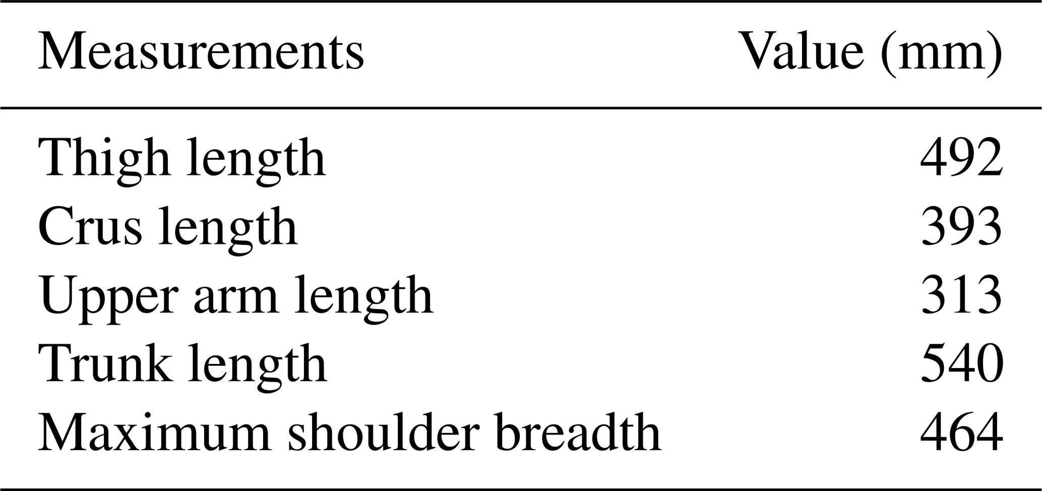
Most patients with unilateral limb disorders often caused by stroke are males over 50 years old (Klopcar and Lenarcic, 2006). Therefore, the data on male body size items with a height of 1739 mm and an age of 36 years or above in GB/T 10000-1988 were selected as reference data and are listed in Table 1.
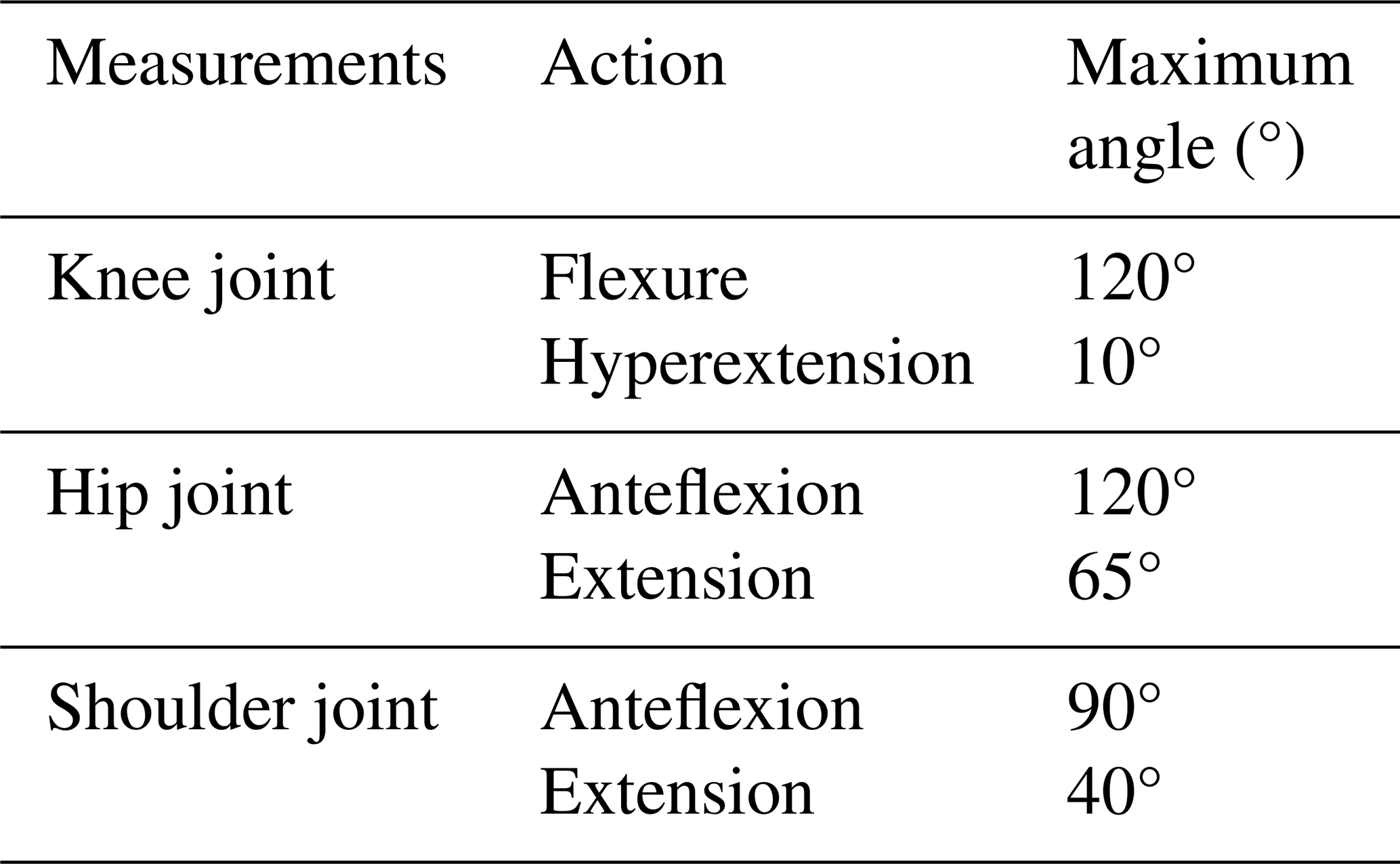
Anatomically, the human body can be divided into three reference planes: the horizontal plane, the coronal plane, and the sagittal plane (Lo and Xie, 2012). Among them, the movement of the limbs in the sagittal plane is the main movement that consumes the most energy. Therefore, the sagittal plane is selected as the design reference for the leg and arm linkages (Neumann, 2013). When the knee joint, hip joint, and shoulder joint perform flexion and extension movements in the sagittal plane, the joint movement angle has a certain range (Wong and Mir-Nasiri, 2012). The movements and maximum angles of human joints in the sagittal plane are shown in Table 2.
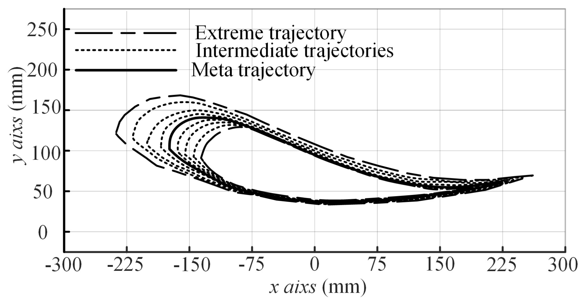
The ankle joint is the joint that bears the most weight in the human body and is an important joint for achieving lower limb movement functions. The ankle joint trajectory is an important reference for designing gait trainers. In previous studies, the gait trajectory of the human ankle joint is like a water droplet shape, with a sharp front and a wide rear. Figure 1 shows the nine gait trajectories specified in the gait trajectory database (Cao et al., 2020; Aimedee et al., 2016). The nine gait curves overlap at the bottom because the height of the ankle joint relative to the ground is close.
4.1 Design concept of linkage mechanism
The leg mechanism is the kinematic heart of the system. The degree to which its end-effector path matches the normative ankle trajectory is a primary determinant of the device's therapeutic quality. While simpler linkages like four-bar or six-bar mechanisms are common in gait training devices due to their lower complexity, they possess fewer links and thus fewer independent design parameters for optimization. This can limit their ability to accurately replicate the complex, nonuniform curvature of a biological gait path.
In previous studies, it has been found that the eight-bar mechanism has better trajectory accuracy compared to the six-bar mechanism (Chung et al., 2001). Based on the above content, research on the wooden ox and gliding horse, and Yan's mechanical innovation theory, an eight-bar motion chain with a 4–4–6 closed loop is selected as the leg linkage mechanism (Lee et al., 2021). Yan's mechanical innovation method is a method of mechanical design based on the topological characteristics of mechanical devices. By analyzing specific mechanical devices to identify their universality, appropriate designs are selected based on actual needs (Yan et al., 2022).
To ensure that the arm mechanism can perform movements similar to the leg mechanism, the size and shape of the arm mechanism rods can be designed to be the same as the size and shape of some of the leg mechanism rods. It is easy to know that when the leg crank and arm crank move at an equal angular velocity, the angular velocity of the swing rod in each mechanism is the same. Therefore, the arm mechanism is a six-bar mechanism obtained by subtracting one Assur group from the eight-bar mechanism of the leg.
4.2 Design and analysis of leg mechanism
The structural diagram of the leg mechanism is obtained, as shown in Fig. 2a, and then the coordinate system is established as shown in Fig. 2b. The frame (ABC) is fixed, and the crank (AD), ternary coupler link (DEH), and ternary rocker (BEF) constitute the crank rocker mechanism. The frame, thigh rod (CGJ), ternary coupler link (DEH), and binary coupler link (FG) constitute the double-rocker mechanism.
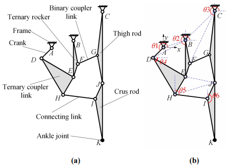
Figure 2The leg mechanism. (a) Structural diagram of the leg mechanism. (b) Coordinate system of the leg mechanism.
In the figure, point K represents the ankle joint. The degree of freedom of the mechanism is as follows:
This formula is the Gruebler criterion for planar mechanisms, used to calculate the number of degrees of freedom (F), which represents the number of independent inputs required to fully define the position of the mechanism. Here, n is the number of links, pL is the number of lower pairs (1-DOF joints like revolute or prismatic joints), and pH is the number of higher pairs (2-DOF joints like a pin in a slot). For our leg mechanism, there are n = 7 links and pL = 10 revolute joints. This results in F = 1, confirming it is a single-degree-of-freedom mechanism.
Using geometric methods for kinematic position analysis – that is, determining the positions of each motion pair through geometric relationships – suppose the lengths of rods AD, DE, BE, BF, EF, FG, CG, GJ, CJ, DH, EH, HI, IJ, IK, and JK are LAD, LDE, LBE, LBF, LEF, LFG, LCG, LGJ, LCJ, LDH, LEH, LHI, LIJ, LIK, and LJK, the point A is the origin, the coordinates of point B are (Bx,By), and the coordinates of point C are (Cx,Cy), then we can calculate the coordinates of each point.
First, suppose the angle between crank AD and the positive direction of the x axis to be θ1; then the position of point D is as follows:
Supposing the angle between BE and the positive direction of the x axis to be θ2, as well as the connection point B and point D, then the cosine law arctangent formula is applied to ΔBDE and ΔBEF, and the positions of point E and point F are as follows:
Supposing the angle between CG and the positive direction of the x axis to beθ3, as well as connection point C and point F, then we know the coordinates of point G and point J:
Supposing the angle between DE and the negative direction of the x axis to be θ4, the position of point H is as follows:
In the end, supposing the angle between HI and the positive direction of the y axis to be θ5 and the angle between IJ and the positive direction of the y axis to be θ6, the positions of point I and point K are as follows:
At this point, the kinematic analysis of the leg mechanism has been completed. The next step is to optimize the trajectory of the leg mechanism based on the ankle joint trajectory mentioned earlier. To find the set of link lengths that best achieves the desired motion, a constrained numerical optimization was performed using the fmincon function in MATLAB. This process involves defining an objective function to be minimized, subject to a set of constraints that ensure the mechanical viability and ergonomic safety of the resulting design.
To ensure that the length of the rod meets the requirements and facilitates calculation, LCJ is 492 mm, LJK is 393 mm, LBE is 250 mm, LAD is 100 mm, the predetermined coordinates of point B are (100, 50), and point C is (350, 250). Design variables and the initial values of design variables are x0 and x. The remaining rod length is the desired target to establish an objective function f(x) based on the connecting rod curve (Kxi,Kyi) and the given curve (x,y), as shown in the following equations:
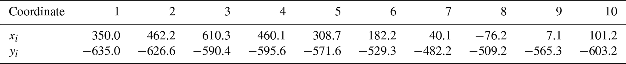
To ensure that the end output trajectory meets the requirements, based on the data in Sect. 2, 10 predetermined position points are taken as shown in Table 3.
A total of 10 points not only provides sufficient constraint information for the algorithm to ensure the accuracy of trajectory fitting but also avoids a sharp increase in computational complexity caused by an excessive number of points, thus preventing the optimization process from being overly time-consuming or falling into a local optimum.
Next, determine the linear constraint. The eight-bar mechanism can move smoothly with constraints. The rod length value of the rod group meets the rod length condition of the crank rocker mechanism, which can be listed as follows:
The length value of the rod group meets the length condition of the double-rocker mechanism, which can be listed as follows:
The linear constraints in Eqs. (20)–(23) are based on the Grashof condition. This condition ensures that the crank rocker and double-rocker sub-chains can move smoothly without locking. For a crank rocker mechanism, the sum of the lengths of the shortest and longest links must be less than or equal to the sum of the other two links, which guarantees that the shortest link (the crank) can perform a full revolution.
Subsequently, determine the nonlinear constraints. The angle between CJ and JK represents the angle of the knee joint, and the angle between rod CJ and the negative direction represents the angle of the hip joint:
The nonlinear constraints in Eqs. (24) and (25) are derived directly from the human factor data presented in Table 2. These inequalities ensure that the motion of the mechanism does not force the user's hip and knee joints beyond their safe and natural range of motion during the rehabilitation exercise, which is a critical safety and comfort consideration.

According to the above formula, increase the crank angle from 0 to 360° in steps of 0.1° and obtain the optimal, as shown in Table 4. At this point, the objective function is f(x)=0.76.
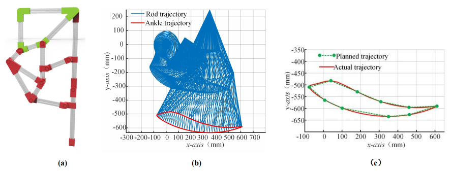
Figure 3The leg mechanism. (a) Model of the leg mechanism. (b) Track of each member and the foot end of the leg mechanism. (c) Planned trajectory and ankle trajectory.
Based on the results, a leg mechanism model diagram is established as shown in Fig. 3a. The trajectory of the rod during one revolution of the crank is shown in Fig. 3b.
The predetermined ankle joint trajectory and the optimal ankle joint trajectory are shown in Fig. 3c. From the figure, the swing range of the large leg in the leg mechanism of the rehabilitation mechanism is similar in size, and the end trajectory of the link mechanism is like a water droplet shape, which meets the expected design.
4.3 Design and analysis of arm mechanism
Having established the optimized design for the leg mechanism, the next critical step is to design an arm mechanism that operates in kinematic synergy with it. This directly addresses the referee's query regarding the basis for the arm mechanism's design parameters. The design is not arbitrary but is derived directly from the leg mechanism to ensure coordinated motion.
The principle of kinematic synergy is achieved by creating a strong structural correlation between the arm and leg mechanisms. The arm mechanism is designed as a six-bar linkage, which is effectively a simplified subset of the eight-bar leg mechanism. This is accomplished by making several key components of the arm mechanism dimensionally identical to their counterparts in the leg mechanism. Specifically, the frame of the arm mechanism (A1 B1 C1) has the same dimensions as the frame of the leg mechanism (ABC). The ternary rocker of the arm mechanism (B1 E1 F1) is identical to the ternary rocker of the leg mechanism (BEF). The connecting link (F1 G1) is identical to the coupler link (FG) in the leg mechanism.
Building on this, we set the length of the head connecting rod D1E1 to 255.79 mm, a value that references the corresponding link in the leg mechanism to maintain continuity in motion transmission. The length of the upper arm rod C1H1 is set to 400 mm. This value was determined based on the human factor engineering data in Table 1 (upper arm length of 313 mm) while also considering a margin for practical wear and range of motion, aiming to ensure the arm swing is both comfortable and effective. Based on these dimensions, a model of the arm mechanism is obtained, as shown in Fig. 4.
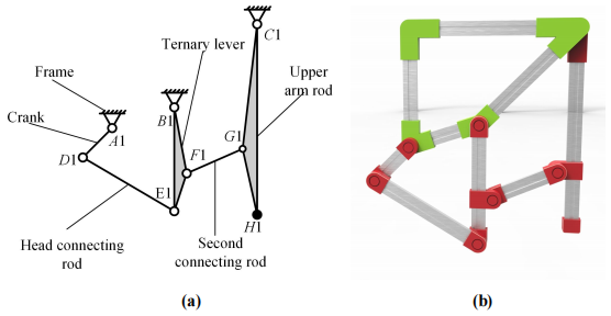
Figure 4The arm mechanism. (a) Structural diagram of the arm mechanism. (b) Model of the arm mechanism.
The above constitutes the design of the arm mechanism. Due to the similarity in structure and size between the arm and leg mechanisms, a coordinated movement can be achieved. However, to ensure this coordination is maintained precisely throughout the entire motion cycle, a dedicated transmission system is required to mechanically link the input cranks of the arm and leg mechanisms.
5.1 Design concept of back mechanism
Having designed the individual leg and arm mechanisms, the next critical step is to ensure they work in unison to produce the desired contralateral gait pattern. To achieve this, a transmission system is required to kinematically couple the input crank of the arm mechanism with the input crank of the leg mechanism on the same side of the user's body. This system, which we term the “back mechanism”, must transmit the rotational motion with a constant velocity ratio, ensuring that for every degree of rotation in the leg mechanism's crank, the arm mechanism's crank rotates by the same amount and in the same direction. This precise coupling is essential for the coordinated operation of the entire rehabilitation device.
To complete the predetermined movement of the rehabilitation mechanism, the crank in the leg mechanism and the crank in the arm mechanism need to move at the same angular velocity and in the same direction to ensure the coordinated operation of the leg and arm movements. To achieve this critical synchronization requirement, it is possible to decompose the back mechanism into a combination of two spatial vertical axis transmission mechanisms and a parallel axis transmission mechanism through a series mechanism innovation method (Li et al., 2022).
5.2 Selection of vertical axis transmission mechanism
The hypothetical coupling theory stipulates that if the distribution of structural components is symmetrical about the plane of the angular bisector between the input and output shafts, then the input and output cranks of the mechanism will have equal angular velocities (Shi et al., 2021). This theoretical characteristic is critical for the back mechanism, which needs to ensure that the leg and arm cranks maintain the same angular velocity and direction to achieve coordinated movement; thus, the RCCR mechanism is selected as the vertical axis transmission mechanism here – it is an over-constrained spatial four-bar mechanism that can adapt well to spatial transmission. The RCCR structure is a type of four-bar linkage in mechanical systems, with its name derived from the sequential types of its four kinematic pairs: Revolute joint (R), Prismatic joint (C), Prismatic joint (C), and Revolute joint (R). The components are connected by cylindrical or rotary pairs, and the low pair connection has good wear resistance (Hao et al., 2020).
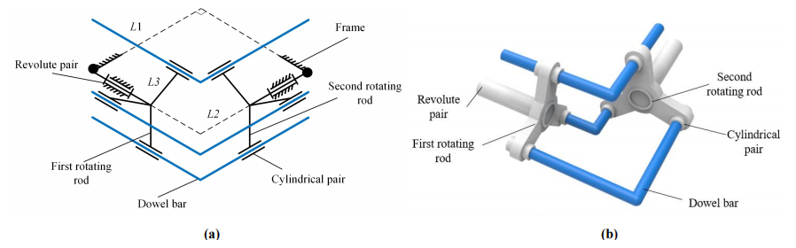
Figure 5The vertical axis transmission mechanism. (a) Structural diagram of the RCCR mechanism. (b) Model of the RCCR mechanism.
The RCCR mechanism with a single pair of dowels has a motion imbalance problem. Currently, the motion of the mechanism is uncertain. Therefore, the RCCR mechanism with three dowels is selected for use here. The mechanism diagram and model diagram of the mechanism are as shown in Fig. 5.
Suppose the distance from the plane where the input handle is located to the plane where the crankshaft is located is L1, the distance from the plane where the input handle is located to the axis of the output crank is L2, and the radius of rotation from the plane where the input handle is located to the plane where the input and output cranks are taken is L3. L1 is 300 mm, L2 is 160 mm, and L3 is 40 mm.
Currently, the degrees of freedom of the mechanism are as follows:
The entire vertical axis constant velocity mechanism can transmit power of the same magnitude and opposite direction. Therefore, based on geometric knowledge, the parallel axis constant velocity mechanism in the rear mechanism needs to transmit constant velocity reverse motion to achieve the predetermined goal.
5.3 Design and analysis of parallel axis transmission mechanism
According to the hypothetical coupling theory, it is known that when the connecting rod mechanism satisfies the constant angular speed transmission, the shape and size of the input and output cranks are the same, and the input structure is the same as the input structure.
Therefore, two simple linkage mechanisms can be chosen. The output end of one linkage mechanism is connected in series with the input end of another linkage device, and the position of the end components can be adjusted to rotate the components in reverse. The structure of the parallel axis transmission mechanism is shown in Fig. 6, and its components include a lower crank and lower slider located below the mechanism, an upper crank and upper slider located above the mechanism, a transmission slider in the middle, and a frame.
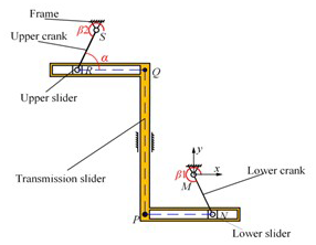
The lower slider and lower crank are hinged through a rotating pair at point N, while the upper slider and upper crank are hinged through a rotating pair at point R. Points P and Q are the hinge points between the transmission slider and the two cranks. The crank lengths are LMN and LRS, respectively. The distance from the origin to the straight-line PQ is LMP, and the distance from point P to point Q is LPQ.
Supposing the included angle between the lower crank (MN) and the positive direction of the x axis is β1, we set the lower crank (MN) at angular speed ω, and the uniform circular motion of t was carried out, and we set the included angle between upper rod RS and the x axis after running for a period as α. Then, the coordinates of pointR can be calculated:
The speed of the upper crank should be the same as that of the lower crank. At this time, supposing the included angle between the upper crank (MN) and the positive direction of the x axis is β2, the speed can be −ω or ω, and setting the coordinates of point R to be R1 and R2, the coordinates of point R1 and R2 can be obtained easily.
Derive point N, point R1, and point R2, and the resultant velocity of point N, point R1, and point R2 can be solved:
The velocity of points N and R is related to the input angular speed and the length of the rod and has nothing to do with the initial position angle of the two rods. When the velocity of the two points is equal in the opposite direction, the initial angle follows Eq. (35), and two points have the same speed, Eq. (36) is as follows:
Therefore, when the initial angle of the input rod and output rod follows Eq. (35) but does not follow Eq. (36), the transmission goal of equal velocity reverse direction can be achieved.
From the perspective of human factor engineering, the length of the crank is 100 mm, the horizontal distance from point M to point N is 270 mm, and the vertical distance from point M to point N is 540 mm, which is also the length of PQ. By arranging the vertical axis transmission device at both ends of the parallel axis transmission device, the back mechanism is obtained, as shown in Fig. 7.
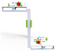
The mechanism shown in the diagram connects the user's right leg and left arm, and by changing the position of the mechanism, another motion chain that matches the user's left leg and right arm is obtained.
6.1 Overall model establishment
Based on the above calculation data and human-factor-engineering-related data, the mobile support is modeled. The mobile bracket overlaps with the frame mentioned above and two motion chains are arranged in a staggered manner on the mobile bracket to form the overall rehabilitation mechanism, as shown in Fig. 8a.
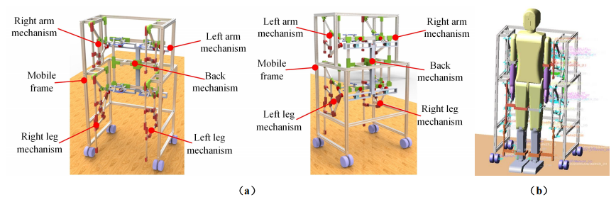
Figure 8Connecting rod rehabilitation mechanism. (a) Overall model of rehabilitation mechanism. (b) Models in Adams.
This rehabilitation assistance device is an unpowered auxiliary mechanism that requires the user's power to drive the mechanism. Therefore, a manikin is designed, and power is applied at the joints of the model to check whether the rehabilitation mechanism meets the target. After cooperating with the rehabilitation mechanism in SolidWorks, convert the assembly format, and import it into Adams. The completed model is shown in Fig. 8b.
6.2 Overall model establishment and simulation preparation
After importing the model into Adams, set the motion pair. Establish the contact relationship between the human body model, mobile support, and the ground. Set up gravity and friction in the simulation environment to complete the simulation preparation work.
In previous studies, the motion curve of the human hip joint was close to the harmonic motion curve or cubic function curve, while the stride frequency of healthy individuals was close to one step per second. Therefore, the step function is chosen as the driving function, with the right arm and right leg of the human model as the active components, and the driving force is applied to the right shoulder joint and right hip joint.
Set the simulation time to 8 s and set the number of simulation steps to 300. After the simulation is completed, data analysis will be conducted on the hip, knee, shoulder, and ankle joints.
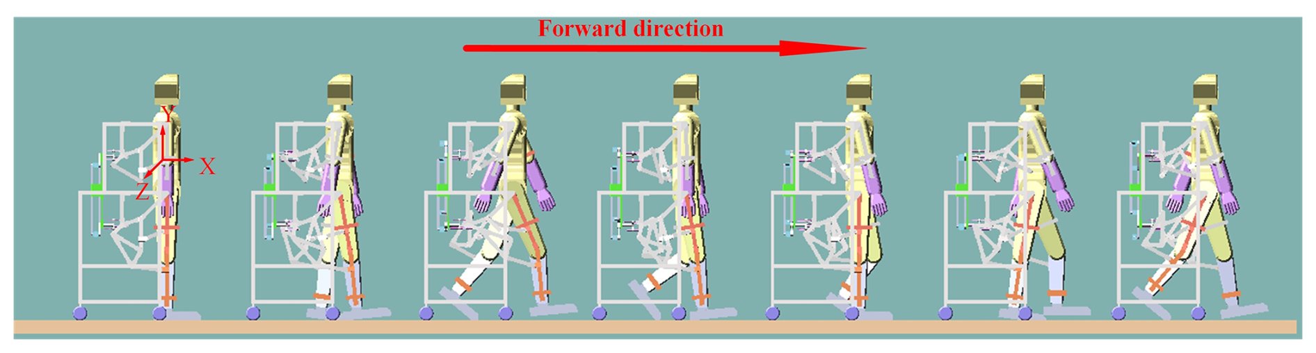
Using Adams and MATLAB to perform image rendering on post-processing data, the images shown in Figs. 8, 9, and 10 were obtained. The simulated gait from rest to walking is shown in Fig. 10, followed by alternating movements of the legs and arms until it stops.
6.3 Simulation and benchmark comparison
The overall model, including the human mannequin, was established in Adams as shown in Fig. 9. To validate the output, the simulated ankle trajectory was compared against a standard gait trajectory from biomechanics literature (Whittle, 2014).
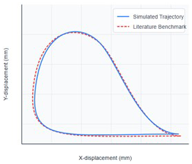
Figure 10 shows the comparison between our simulated ankle trajectory and the literature benchmark. Visually, the two trajectories show strong similarity in shape and scale. To quantify this, the root mean square error (RMSE) between the two trajectories was calculated, yielding a value of 18.5 mm, which is less than 5 % of the total trajectory length, indicating a close fit. Key gait parameters are also compared in Table 5. The simulated step length and maximum foot clearance are within 6 % of the benchmark values, further validating that the mechanism's motion is close to normal.
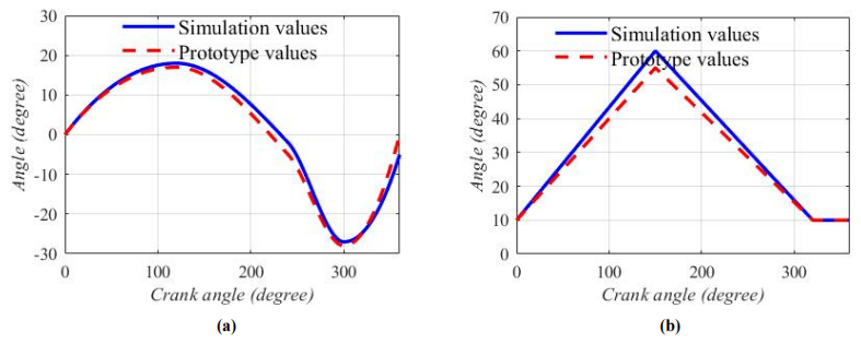
Figure 11Comparison of prototype and simulation results. (a) Hip joint angle. (b) Knee joint angle.
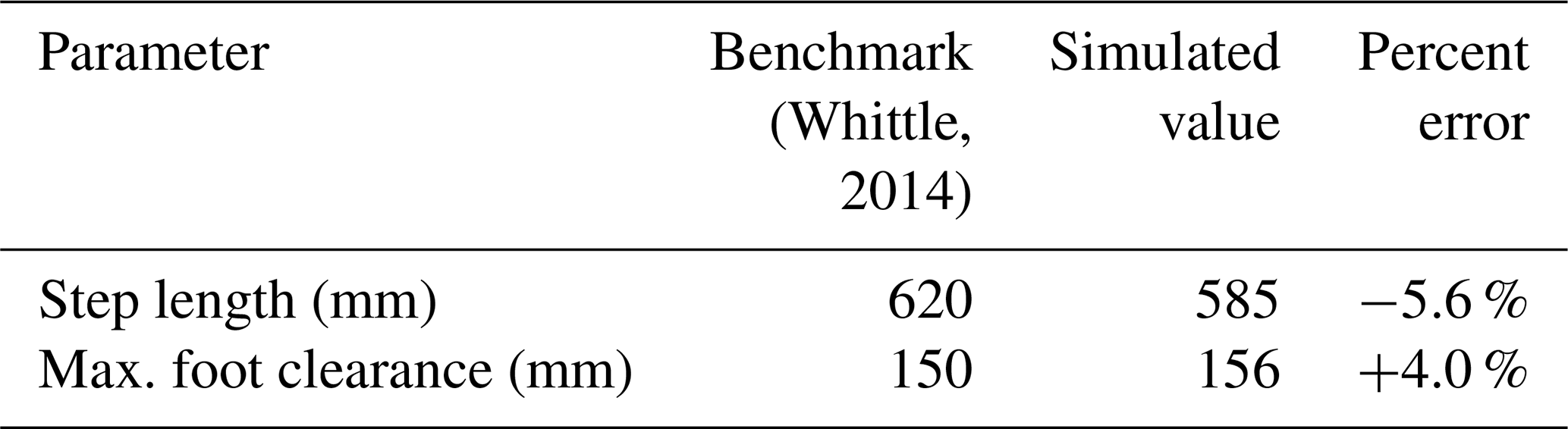
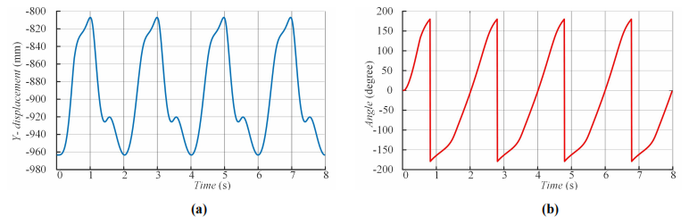
Figure 12(a) The displacement of the right ankle joint in the y direction. (b) The crank angle of the right leg mechanism.
6.4 Prototype performance and quantitative analysis
A proof-of-concept prototype was constructed using 3D-printed parts and aluminum profiles to verify the design's real-world kinematic performance. The articulating joints and connectors were 3D-printed using polylactic acid (PLA) filament (1.75 mm diameter, printed with a 0.4 mm nozzle at 210 °C), chosen for its rapid prototyping capabilities and sufficient rigidity for kinematic validation. The main structural frame was assembled from 20 × 20 mm T-slot 6061 aluminum alloy profiles, selected for their high strength-to-weight ratio and ease of assembly.
We collected data on the angle changes of the hip and knee joints from the prototype and compared them to the simulation data (Fig. 11).
Table 6Quantitative error analysis of prototype vs. simulation. n/a: not applicable.
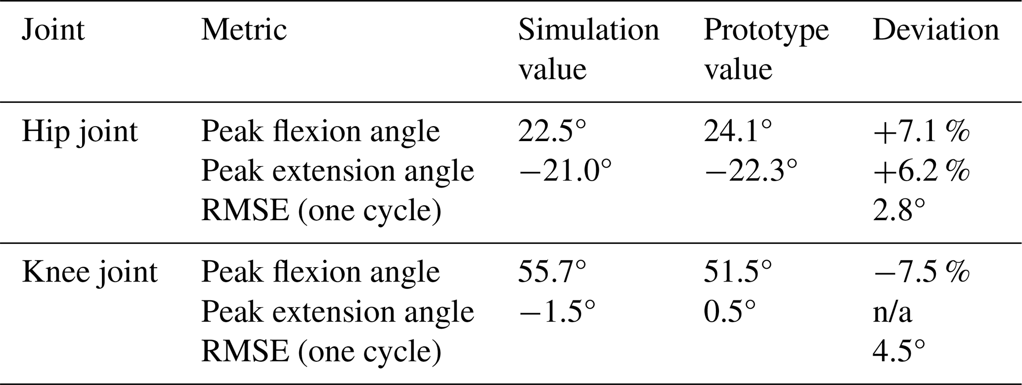
While the plots show strong qualitative agreement in the overall motion trend, some deviations are apparent. To quantify these deviations, a detailed error analysis was performed, and the results are summarized in Table 6. The analysis reveals that the peak flexion and extension angles measured from the prototype deviate from the simulated values by no more than 7.5 %. More importantly, the overall root mean square error (RMSE) for the entire joint angle trajectory over one cycle was calculated to be 2.8° for the hip joint and 4.5° for the knee joint. These small, quantified errors are within an acceptable range for a first-generation, proof-of-concept prototype. They can be attributed to predictable real-world factors such as the material elasticity and compliance of the 3D-printed PLA parts, friction within the pin joints, and minor misalignments introduced during manual assembly. This quantitative analysis successfully demonstrates that the physical prototype accurately reproduces the intended kinematic patterns of the theoretical design with quantifiable and acceptable errors, thus validating the viability of the mechanism's construction.
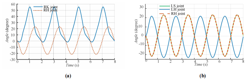
Figure 13(a) Changes in angle between the RK joint and the RH joint. (b) Changes in angle between the RK joint and the RH joint.
6.5 Analysis of simulation result
The displacement of the right ankle joint (RH joint) in the y direction is shown in Fig. 12a, and the change of the crank angle of the right leg mechanism is shown in Fig. 12b. The displacement range of the right ankle joint in the y direction is −965 to −809 mm, and the change of the crank of the right leg mechanism is −180 to 180°. When the swing rod is used as the driving part, the ankle joint can reach a predetermined height.
The angle changes of the right knee joint (RK joint) and the right hip joint (RH joint) are shown in Fig. 13a. The change range of the RK joint angle is −1.5 to 55.7°, and the change range of the RH joint angle is −21 to 23° in the simulation process. The change cycle of the two angles is stable, and the variation range of the angle is within a reasonable range, indicating that the leg structure of the rehabilitation mechanism can meet the principle of human factor engineering.
Figure 13b shows the angle changes of the RH joint, left shoulder joint (LS joint), and left hip joint (LH joint). From the figure, the image curves of the left shoulder joint and the right shoulder joint are symmetrical, and the images of the right hip joint and the left shoulder joint completely overlap, with the same period of image change, which meets the design objectives.
Figure 14 reflects the displacement changes of the ankle joint during the simulation period. The black line in the figure represents the relationship curve between time and displacement in both directions, while the colored plane represents the fitting plane of the relationship curve. From the graph, the motion curve of the right ankle joint in the x direction is close to a straight line. Within an 8 s simulation time, the displacement of the right ankle joint in the x direction is 4900 mm, with a periodic increase in horizontal displacement, approximately 1200 mm forward per cycle. In the y direction, the displacement change curve is close to the simple harmonic motion curve, which is in line with human engineering knowledge.
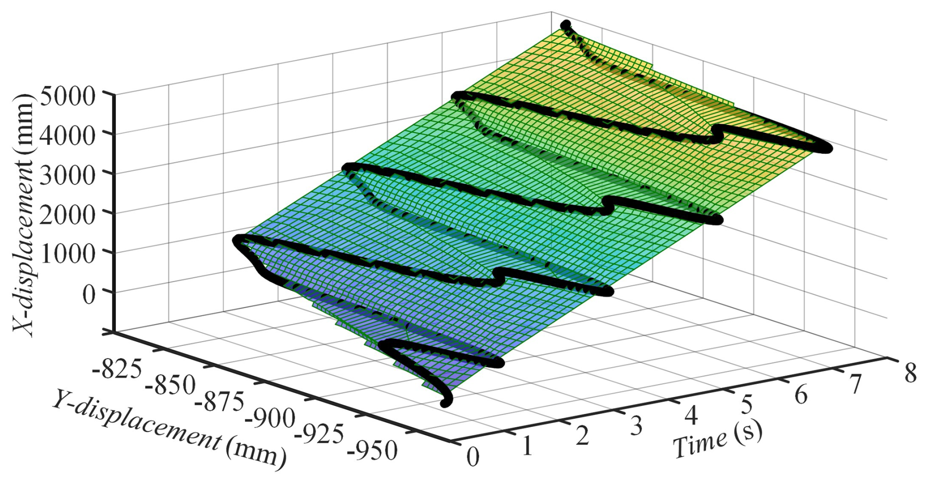
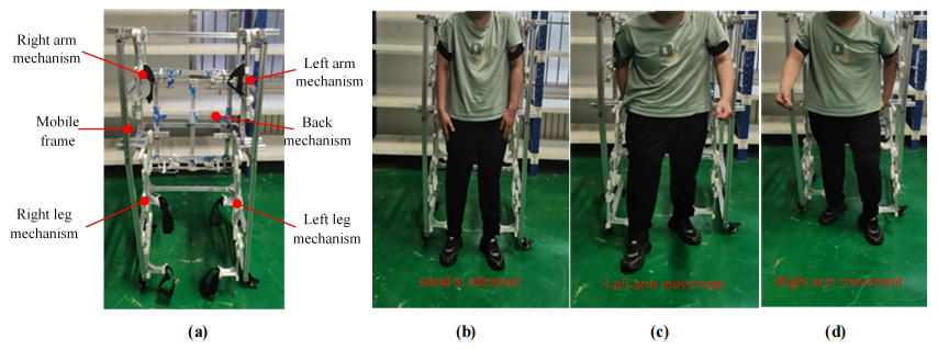
Figure 15Prototype experiment. (a) Prototype. (b) User and prototypes. (c) Prototype inspection 1. (d) Prototype inspection 2.
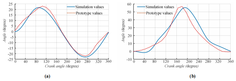
Figure 16Comparison of prototype and simulation results. (a) Hip joint angle. (b) Knee joint angle.
6.6 Analysis of prototype experiment
Build a prototype using 3D-printed parts and aluminum profile standard parts, as shown in Fig. 15a when the prototype is unoccupied, and the cooperation between the user and the prototype is shown in Fig. 15b below. Subsequently, the user preliminarily checked the performance of the prototype. The performance inspection of the left arm and right leg support chain is shown in Fig. 15c, and the inspection of the right arm and left leg support chain is shown in Fig. 15d, indicating that the linkage performance of the motion chain meets the requirements.
Collect data on the angle changes of the crank, hip, and knee joints in the prototype and combine them with simulation data to draw charts. The actual and theoretical angle changes of the knee joint are shown in Fig. 16a, while the actual and theoretical angle changes of the hip joint are shown in Fig. 16b. There is a deviation between the time when the angle reaches its peak in the prototype and the time when the theoretical peak arrives, and the peak size is close, which alleviates the phenomenon of overextension.
The validation results confirm the viability of the proposed mechanism. Simulation analysis shows that the optimized eight-bar leg mechanism generates an ankle trajectory that is quantitatively “close to normal”, with low error compared to biomechanical benchmarks (Table 5). This high fidelity justifies the choice of a more complex eight-bar linkage over simpler alternatives. The quantitative analysis of the prototype further validates the design, revealing small, acceptable deviations from the simulation (Table 6) that can be attributed to the use of proof-of-concept materials and provide a baseline for future refinement.
The primary limitation of the current design is its passive nature, which makes it low-cost but unsuitable for patients with severe weakness. Future work should address this by exploring an active-assistive version with a motor and control system. Additionally, manufacturing a clinical-grade version with higher-precision methods would minimize the mechanical imperfections noted in the prototype analysis.
Most importantly, while this study confirms the kinematic soundness of the design, the next essential step is clinical validation. Future research must involve trials with the target patient population to assess therapeutic efficacy using established clinical scales (e.g., Fugl–Meyer Assessment, functional independence measure) and instrumental measurements like electromyography (EMG) to quantify functional improvements and neuromuscular recovery.
This paper presents the design and validation of a novel linkage-type rehabilitation mechanism. After determining the design goals using mechanical innovation methods and human factor engineering knowledge, we sequentially designed an eight-bar leg mechanism, a coordinating arm mechanism, and a back transmission mechanism.
The design was validated through simulation and a proof-of-concept prototype. The simulation results prove that the designed mechanism can generate a gait trajectory that closely matches published data for a normal human gait. The prototype experiments, supported by quantitative error analysis, confirm that the physical hardware successfully reproduces the intended kinematic patterns. While the prototype experiments indicate that there is still room for improvement in mechanical precision, the overall design is proven to be viable. The passive-driven rehabilitation mechanism proposed in this paper enables users to complete limb movements in the sagittal plane through their own strength, offering a simple, energy-saving, and innovative approach for the research and design of rehabilitation mechanisms.
All the data used in this article can be made available upon reasonable request. Please contact Kan Shi (kan.shi@hotmail.com) and Dongbin Zhang (202482050059@sdust.edu.cn).
KS and DZ proposed and developed the overall concept of the paper and conducted the mechanism design and analysis. DZ wrote the whole paper. HW and RW assisted in the prototype construction work.
The contact author has declared that none of the authors has any competing interests.
Publisher's note: Copernicus Publications remains neutral with regard to jurisdictional claims made in the text, published maps, institutional affiliations, or any other geographical representation in this paper. While Copernicus Publications makes every effort to include appropriate place names, the final responsibility lies with the authors.
This paper was edited by Benliang Zhu and reviewed by two anonymous referees.
Aimedee, F., Gogu, G., Dai, J. S., Bouzgarrou, C., and Bouton, N.: Systematization of morphing in reconfigurable mechanisms, Mech. Machine Theory, 96, 215–224, 2016.
Bai, S., Christensen, S., and Islam, M. R. U.: An upper-body exoskeleton with a novel shoulder mechanism for assistive applications, 2017 IEEE Int. Conf. Adv. Intell. Mech., 1041–1046, https://doi.org/10.1109/AIM.2017.8014156, 2017.
Barbosa, A. M., Carvalho, J. C. M., and Gonçalves, R. S.: Cable-driven lower limb rehabilitation robot, J Braz. Soc. Mech. Sci. Eng., 40, 245, https://doi.org/10.1007/s40430-018-1172-y, 2018.
Cao, W., Chen, C., Hu, H., Fang, K., and Wu, X.: Effect of Hip Assistance Modes on Metabolic Cost of Walking With a Soft Exoskeleton, IEEE T. Autom. Sci. Eng., 18, 426–436, https://doi.org/10.1109/TASE.2020.3027748, 2020.
Chung, Y., Park, C., and Harashima, F.: A position control differential drive wheeled mobile robot, IEEE T. Ind. Electron., 48.4, 853–863, 2001.
Ghrairi, K., Chaker, A., Salah, S., and Bennour, S.: Development of a cable-driven parallel robots for functional rehabilitation, design and modeling of mechanical systems, Springer, Cham, 554–563, https://doi.org/10.1007/978-3-031-14615-2_62, 2023.
Godoy, J. C., Campos, I. J, Pérez, L. M., and Muñoz, L. R.: Nonanthropomorphic exoskeleton with legs based on eight-bar linkages, International Journal of Advanced Robotic Systems, 15, https://doi.org/10.1177/1729881418755770, 2018.
Grosu, S., De Rijcke, L., Grosu, V., Geeroms, J., Vanderborght, B., Lefeber, D., Rodriguez-Guerrero, C.: Driving robotic exoskeletons using cable-based transmissions: A Qualitative Analysis Overview, Applied Mechanics Rev., 70, 060801, https://doi.org/10.1115/1.4042399, 2019.
Hao, Y. L., Tian, Y. B., Wu, J. X., Li, Y. Z., and Yao, Y. A.: Design and locomotion analysis of two kinds of rolling expandable mobile linkages with a single degree of freedom, Frontiers of Mechanical Engineering, 15, 365–373, https://doi.org/10.1007/s11465-020-0585-3, 2020.
Hramov, A. E., Maksimenko, V. A., and Pisarchik, A. N.: Physical principle of brain–computer interfaces and their applications for rehabilitation, robotics and control of human brain states, Physics Reports, 918, 1–133, https://doi.org/10.1016/j.physrep.2021.03.002, 2021.
Klopcar, N. and Lenarcic, J.: Bilateral and unilateral shoulder girdle kinematics during humeral elevation, Clin. Biomech., 21, 20–26, https://doi.org/10.1016/j.clinbiomech.2005.09.009, 2006.
Lee, J., Li, L., Shin, S. Y., Deshpande, A. D., and Sulzer, J.: Kinematic comparison of single degree-of-freedom robotic gait trainers, Mech. Mach. Theory, 159, 104258, https://doi.org/10.1016/j.mechmachtheory.2021.104258, 2021.
Li, S.-W., Shi, K., Wang, M.-J., and Yao, Y.-A.: Structural analysis of ancient Chinese textile mechanisms, Mech. Sci., 13, 625–634, https://doi.org/10.5194/ms-13-625-2022, 2022.
Lim, Y. P., Lin, Y. C., and Pandy, M. G.: Effects of step length and step frequency on lower-limb muscle function in human gait, J. Biomech., 57, 1–7, https://doi.org/10.1016/j.jbiomech.2017.03.004, 2017.
Lo, H. S. and Xie, S. Q.: Exoskeleton robots for upper-limb rehabilitation: State of the art and future prospects, Med. Eng. Phys., 34, 261–268, https://doi.org/10.1016/j.medengphy.2011.10.004, 2012.
Moisè, M., Morelli, L., Giovacchini, F., Vitiello, N., and Colombina, G.: System for assisting an operator in exerting efforts, WO/2019/016629, https://patentscope.wipo.int/search/en/WO2019016629 (last access date: 6 November 2025), 2019.
Neumann, D. A.: Kinesiology of the musculoskeletal system-e-book: foundations for rehabilitation, Elsevier Health Sciences, ISBN 978-0323287531, 2013.
Qassim, H. M. and Wan Hasan, W. Z.: A review on upper limb rehabilitation robots, Appl. Sci.-Basel, 10, 6976, https://doi.org/10.3390/app10196976, 2020.
Qiao, H., Zhang, S., Chen, Z., and Wang, H.: Improving performance of robots using human-inspired approaches: a survey, Sci. China Inf. Sci., 65, 1–31, https://doi.org/10.1007/s11432-022-3606-1, 2022.
Qin, T., Wang, Q., Su, W., Wei, C., Zhang, Y., and Zhang, J.: Motion planning and control strategy of a cable-driven body weight support gait training robot, Mech. Sci., 14, 413–427, https://doi.org/10.5194/ms-14-413-2023, 2023.
Saelens, B. E., Sallis, J. F., and Frank, L. D.: Environmental correlates of walking and cycling: findings from the transportation, urban design, and planning literatures, Ann. Behav. Med., 25, 80–91, https://doi.org/10.1207/S15324796ABM2502_03, 2003.
Sanjuan, J. D., Castillo, A. D., Padilla, M. A., Quintero, M. C., Gutierrez, E. E., Sampayo, I. P., Hernandez, J. R., Rahman, M. H.: Cable driven exoskeleton for upper-limb rehabilitation: A design review, Robotics and Autonomous Systems, 126, 103445, https://doi.org/10.1016/j.robot.2020.103445, 2020.
Shi, K., Lin, S., and Yao, Y.: The method for synthesis of the contact ratio of noncircular bevel gears, Mech. Sci., 12, 165–172, https://doi.org/10.5194/ms-12-165-2021, 2021.
Tang, X.: An overview of the development for cable-driven parallel manipulator, Adv. Mech. Eng., 6, 823028, https://doi.org/10.1155/2014/823028, 2014.
Wang, W., Chen, J., Ji, Y., Jin, W., Liu, J., and Zhang, J.: Evaluation of lower leg muscle activities during human walking assisted by an ankle exoskeleton, IEEE Trans. Industr. Inform., 16, 7168–7176, https://doi.org/10.1109/TII.2020.2974232, 2020.
Whittle, M. W.: Gait Analysis: An Introduction, 1. Elsevier Science, ISBN 978-1483183732, 2014.
Wong, J. J. S. and Mir-Nasiri, N.: Design and Development of Human-Machine Interactive-Force Controlled Powered Upper-Limb Exoskeleton for Human Augmentation and Physical Rehabilitation, IEEE EMBS Conf. on Biomedical Engineering & Sciences, 2012, 465–470, https://doi.org/10.1109/IECBES.2012.6498089, 2012.
Xie, L., Wang, Z., Huang, G., Liu, B., and Zhou, Z.: Mechanical Efficiency Investigation of an Ankle-Assisted Robot for Human Walking With a Backpack-Load, J. Biomech. Eng., 143, 111010, https://doi.org/10.1115/1.4051434, 2021.
Yan, C., Shi, K., Zhang, H., and Yao, Y.: Simulation and analysis of a single actuated quadruped robot, Mech. Sci., 13, 137–146, https://doi.org/10.5194/ms-13-137-2022, 2022.
Zhang, M. and Ban, W.: Efficacy evaluation of acupuncture combined with Lokohelp robot rehabilitation for hemiplegia following acute ischemic stroke, Chinese Journal of Primary Medicine and Pharmacy, 697–700, https://doi.org/10.3760/cma.j.issn.1008-6706.2019.06.015, 2019.
Zou, Y., Wu, X., Zhang, B., Zhang, Q., Zhang, A., and Qin, T.: Stiffness Analysis of Parallel Cable-Driven Upper Limb Rehabilitation Robot, Micromachines-Basel, 13, 253, https://doi.org/10.3390/mi13020253, 2022.
- Abstract
- Introduction
- Integrated design philosophy and system architecture
- Analysis of human factor engineering parameters
- Design and analysis of leg and arm mechanisms
- Back mechanism design
- Analysis of simulation and prototype experimental
- Discussion
- Conclusion
- Data availability
- Author contributions
- Competing interests
- Disclaimer
- Review statement
- References