the Creative Commons Attribution 4.0 License.
the Creative Commons Attribution 4.0 License.
 | 21 Oct 2025
Rub-impact fault diagnosis of rotor systems based on EMD and dynamic CNN
Jinmin Shi
Ruixiao Zhang
Qian Wang
As some of the high-frequency faults in rotating machinery, the early detection and accurate identification of rub-impact faults have attracted much attention. Due to the low vibration property and strong environment noise, it is still a challenge problem to deal with the early diagnosis of rub-impact faults. In this paper, a new rub-impact fault diagnosis method is proposed which consists four phases: the decomposition phase, the dynamic feature extraction phase, the diagnosis model construction phase, and the verification phase. In the first phase, the original vibration signals are decomposed based on empirical mode decomposition (EMD), and the most correlated components are selected using the Pearson correlation coefficient (PCC). Then, in the second phase, the fault dynamics of the selected components are identified based on dynamic learning, which means they are more sensitive to the small faults in the initial stage. In the last phase, a new fault feature deep fusion module is constructed based on the identified dynamics information and integrate into the convolution neural networks to derive the diagnosis model (dynamic CNN). Finally, the misjudgment self-correction mechanism is implemented based on the comparison of fault dynamics in the verification phase. Compared with traditional methods, the experiment results illustrate that the proposed method can detect the rub-impact faults more effectively.
- Article
(4388 KB) - Full-text XML
- BibTeX
- EndNote


Rotor systems, as the most important component of rotating machinery, have been widely used in the areas of key equipment, such as coal mining units, power systems, and aerospace. However, due to long-term exposure to complex working conditions such as high speed and heavy load, rotating machinery is prone to various faults (Miao and Yu, 2024; Shi et al., 2025). Additionally, the manufacturing errors, assemble errors, unbalance forces, improper lubrication, etc., will also exacerbate the occurrence of rotor system failures (Xu et al., 2025; Li et al., 2025). Among those rotor unacceptable faults, rotor rub impact is one of the most common and harmful types of faults (Yang et al., 2024). Rub-impact faults can lead to increased mechanical vibration, temperature rise, and even equipment damage accidents in severe cases (Li et al., 2024a). Therefore, conducting accurate diagnosis research on the rub-impact faults of rotating machinery has important theoretical significance and engineering application value (Wang et al., 2023).
Traditional fault diagnosis methods mainly rely on signal processing and feature extraction techniques, such as Fourier transform and wavelet transform. However, these methods have limitations in processing non-stationary and nonlinear rub-impact fault vibration signals, making it difficult to effectively extract fault features. With the development of the signal processing technique, empirical mode decomposition (EMD) (Prosvirin et al., 2018), variational mode decomposition (VMD) (Xia et al., 2025), and adaptive chirp mode decomposition (ACMD) (Ding and Wang, 2022) have been proposed for the non-stationary and nonlinear signals. Among them, EMD, as an adaptive signal processing method, can decompose complex signals into a series of intrinsic mode functions (IMFs) to better reveal the local fault features of the vibration signals (Hou et al., 2024; Lei et al., 2013). In additional, the EMD method requires the least amount of computing power compared to other time–frequency analysis methods. Therefore, EMD has been widely used in the field of rotating machinery fault diagnosis and has achieved significant results in recent years. Arifin et al. (2025) proposed an enhanced EMD technique to detect the broken rotor bar faults. Liu et al. (2019) used a modified EMD to extract the fault IMFs of a rotor laboratory bench. However, how to use the extracted fault IMFs effectively is still an essential and challenging issue of the diagnosis of rub-impact faults (Li et al., 2024b; Liu et al., 2024).
With the development of sensor technology, the massive amounts of rotor vibration data are easy to be obtained. Due to the efficient processing, automatic feature extraction, and end-to-end diagnostic capabilities, deep-learning-based methods are increasingly being applied in rotating machinery fault diagnosis (Saini et al., 2022; Hou et al., 2024). The convolutional neural network (CNN), as a powerful deep learning model, has made breakthrough progress in the field of image recognition and shown great potential in the field of rotor fault diagnosis (Zhu et al., 2023; Yu and Xie, 2024). Additionally, based on the basic mechanism of CNNs, many other modified CNN algorithms have been proposed, such as multi-mode CNN (Yuan et al., 2018) and residual network (Chen et al., 2024). Yuan et al. (2018) proposed a multi-mode CNN for feature learning and rotor fault diagnosis based on the raw signals and infrared images. Chen et al. (2024) proposed a residual network to address rotor imbalance and misalignment in oil transfer pumps. Regarding the diagnosis of rotor rub-impact faults, Prosvirin et al. (2020) uses deep learning to automatically extract features and identify rubbing faults from observed rotor rubbing vibration signals. Based on the work of Prosvirin et al. (2020), Prosvirin et al. (2022) further proposed a more effective multivariate convolutional neural network model for diagnosing rubbing faults. However, the accuracy and effectiveness of the diagnostic model constructed based on CNNs and other modified CNNs depend on whether the useful fault information can be learned. It is directly related to whether the model has high-quality data input.
Due to the small amplitude of the vibration response in the early stage of rub-impact faults and the relatively small harmonic components related to rub-impact faults, the extracted characteristics of rub-impact faults are easily weakened or overwhelmed by background noise in the vibration signal (Yang et al., 2024). Therefore, the effectiveness of extracting and detecting early weak features of rotor rubbing faults based solely on the time–frequency characteristics or nonlinear indicators is not sufficient. In some serious cases, false alarms or missed alarms of rubbing faults may occur (Kou et al., 2022; Jin et al., 2023). In addition, these methods are also confronted with the “black box” problem in the diagnostic process, lacking transparency or interpretability (Zhu et al., 2023). It leads to the weak generalization ability for different working conditions, and it is also difficult to provide specific reasons when misdiagnosis occurs, resulting in inexplicable self-correction of misjudgments.
In order to identify the more sensitive system fault dynamics information, dynamic learning has been applied to learn the unbalance fault and rub-impact fault of the rotor system (Wang and Chen, 2011). Furthermore, the dynamics information has been shown priority in the rotor unbalance fault diagnosis (Lan et al., 2023). Combining the vibration dynamics characteristics of rotor systems, these model-based methods can provide an effective solution for early diagnosis and trend prediction of gradual faults in nonlinear dynamic systems. It should be noted that the effectiveness depends on the ability to accurately identify the intrinsic dynamics of gradual faults, which is a key step in diagnosing and predicting small gradual faults (Wang et al., 2022; Wang and Wang, 2018).
Inspired by the above methods, a new rub-impact fault diagnosis method based on EMD and dynamic CNN is proposed. Firstly, the original vibration signals are decomposed using EMD to obtain fault-related IMF components. Then, the most correlated IMF components are selected via the Pearson correlation coefficient (PCC) and are input into the dynamic CNN model for feature learning and fault classification. The fault dynamics of the selected components are identified based on dynamic learning, which means they are more sensitive to the small faults in the initial stage. The diagnostic model is constructed based on the identified fault dynamics information. By combining the adaptive signal decomposition capability of EMD and the deep feature extraction capability of dynamic CNN, this method can effectively improve the diagnostic accuracy and robustness of rotor rub-impact faults. Furthermore, the misjudgment self-correction mechanism is implemented by embedding the comparison of fault dynamics. Compared with the traditional methods, the experiments results illustrate that the proposed method can detect the rub-impact faults more effectively.
The main contributions of this paper are as follows:
-
Differently to the signal processing diagnosis methods in Xia et al. (2025) and Ding and Wang (2022), the most sensitive IMF components of the rub-impact faults are extracted based on EMD and PCC, and the running time of the algorithm is greatly reduced.
-
Differently to our previous work in Wang et al. (2022), the identified fault dynamics are employed for the CNN classification process. The dynamic CNN diagnosis model is first proposed for the early detection of rub-impact faults, in which the spatial–temporal features in dynamic information of different fault IMFs can be explored effectively.
-
The experiments indicate that not only can the proposed method be applied to different working conditions, but the misjudgment self-correction mechanism is also implemented based on the clear physical changes in fault dynamics. Furthermore, the problem of unexplained results in traditional CNN-based diagnostic models is solved by employing the misjudgment self-correction mechanism.
This paper is organized as follows. In Sect. 2, the problem formulation is presented. The proposed diagnosis algorithm is illustrated in Sect. 3, and the experiments are shown in Sect. 4. Section 5 gives the conclusions and future studies.
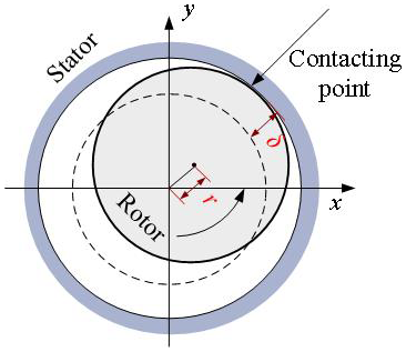
The rub-impact fault diagram is shown in Fig. 1 (Wang et al., 2022). γ is the radial displacement of the rotor, and δ is the clearance between rotor and stator. When the rub-impact fault occurs, the vibration is similar to the normal signals in the initial stage. Due to the environment and other noise, early detection of rub-impact faults becomes more and more difficult. Therefore, how to identify and detect the small rub-impact faults accurately is the key to maintain the safety of rotor systems.
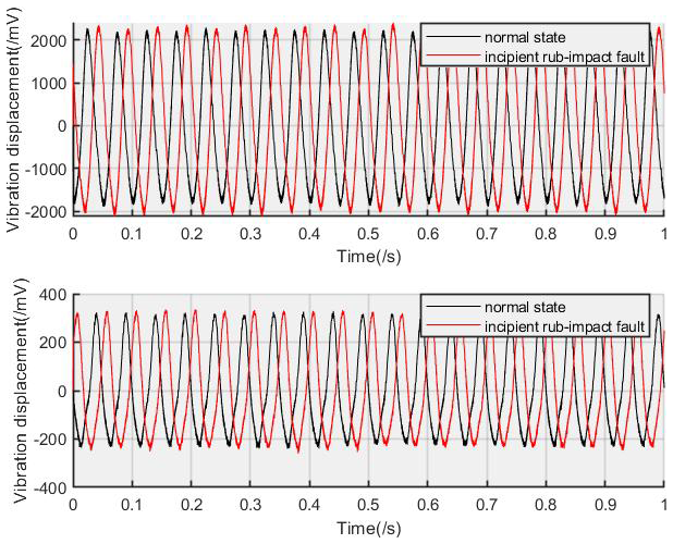
The time-domain waveform of the normal state and incipient rub-impact faults are shown in Fig. 2, associated with horizontal vibration signals (X direction) and vertical vibration signals (Y direction). The vibration signals are collected based on the rotor fault test rig as shown in Fig. 4, and the rotating speed is set to 1200 rpm. In the incipient rub-impact fault stage, it can be seen that it is very difficult to distinguish the incipient faults just based on the time-domain features, especially for the vertical vibration signals. This phenomenon is highly correlated with the simulation results in Fig. 2 of Wang et al. (2022). The early fault detection in this paper is related to diagnosing or monitoring the small rub-impact fault as soon as possible, especially in the incipient fault stage.
According to Wang et al. (2022) and Lan et al. (2023), the vibration phenomenon of rotor systems can be modeled as in the following equation, Eq. (1).
where represents the X-direction vibration signal and Y-direction vibration signal as shown in Fig. 1, f(x,y) represents the system dynamics, v(x,y) is the system uncertainties, and d(xy) is the system noise. In Fig. 2, it is indicated that the changes in the system state caused by the early rub-impact faults are very weak. Specifically, the noise d(xy) has always existed in real applications. It makes the detection of rub-impact faults more difficult.
Inspired by the existing work, it can be concluded that the dynamics changes are more sensitive to the system state changes, which are influenced by the small faults. However, there are two key steps in the fault diagnosis of rub impact. The first one is how to reduce the influence of the noise d(xy) and extract the most related fault information, and the second one is how to identify the system dynamics f(x,y) which are caused by the rub-impact faults under the condition of the existing uncertainty v(x,y). Therefore, the main goal of this paper is to deal with the problem of main feature extraction and fault dynamics identification and classification.
Assumption 1: the collected data on vertical and horizontal vibration are bounded by the occurrence of rub-impact faults.
Remark 1: the main idea of the proposed method is to diagnose the early rub-impact faults, in which the vibration is within a controllable range and will not deviate too far from the healthy state. Therefore, the collected data are considered to be bounded by the occurrence of rub-impact faults.
Assumption 2: the system dynamics f(x,y) cannot be decoupled from the uncertainty v(x,y), and the uncertainties are assumed to be stable in the certain or similar environment.
Remark 2: in most real applications, the sampled signals are very complicated, and the uncertainty components are unknown. In the Wang et al. (2022), it has been verified that the system fault dynamics and the uncertainties can be identified together and that the high diagnosis performance can be achieved. Additionally, the different working conditions are considered, which are related to the generalization of the proposed method.
3.1 EMD and PCC
The EMD method essentially smooths a signal, resulting in the gradual decomposition of fluctuations or trends of different scales in the signal, and producing a series of data sequences with different characteristic scales (Hou et al., 2024; Lei et al., 2013). The series of extracted data sequences are donated as the intrinsic mode functions (IMFs). Furthermore, by performing the Hilbert transform on these IMFs, the time–frequency spectrum of the signal can be obtained, which can reflect the original frequency characteristics of the signal. Therefore, the IMFs are the key information of the vibration signals.
In this part, the vibration signal associated with the horizontal direction x(t) is chosen as the input of the EMD method, and the decomposition results contain n IMFs and a residual mode, i.e., IMF1,IMF2, …, IMFn, and rn.
where rn(t) represents the residual component and the average trend of the signal. Each basic mode component contains components of different time feature scales of the signal, with scales ranging from small to large. Therefore, each decomposition result contains components of different frequency ranges from high to low. The frequency components contained in each frequency range are different and vary with the signal itself. Based on the decomposition mechanism, the noise can also be reduced by suppressing IMFs with high frequency, and the most correlated rub-impact fault components are preserved.
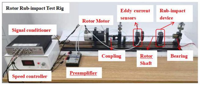
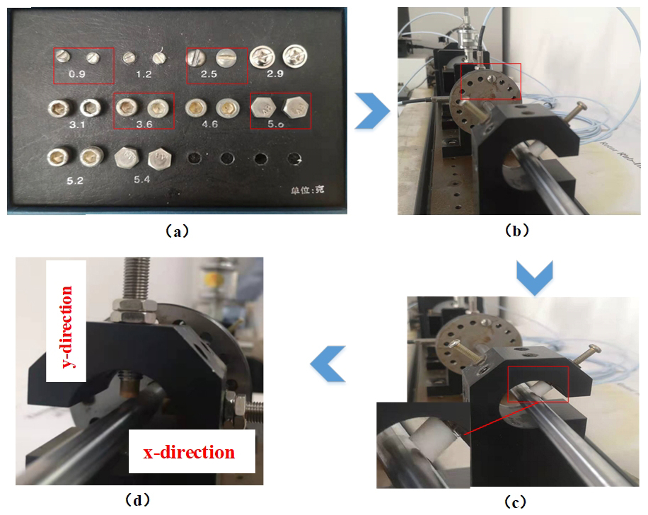
Figure 5Rotor rub-impact fault device. (a) Selection of counterweights. (b) Installation position of counterweights. (c) Fixed rub block. (d) Eddy current sensors.
Additionally, the PCC is used to select the most correlated modes. PCC is a statistical indicator that measures the degree of linear correlation between two variables, with values ranging from −1 to 1. The calculation formula is shown in the following equation, Eq. (3):
where ; m is the number of the IMFs; , and n is the length of signal and IMFs. The threshold is set to γ=0.35 in the experiments, and the IMFs associated with γ≥0.35 are selected for the signal reconstruction; , where γ≥0.35.
Regarding the vibration signal y(t) in the vertical direction, the reconstructed vibration signal yp(t) can be obtained in the same way as xp(t). Based on the obtained signals xp(t) and yp(t) associated with the most correlated fault information, the following dynamic CNN model is built for the diagnosis of the small rub-impact faults.
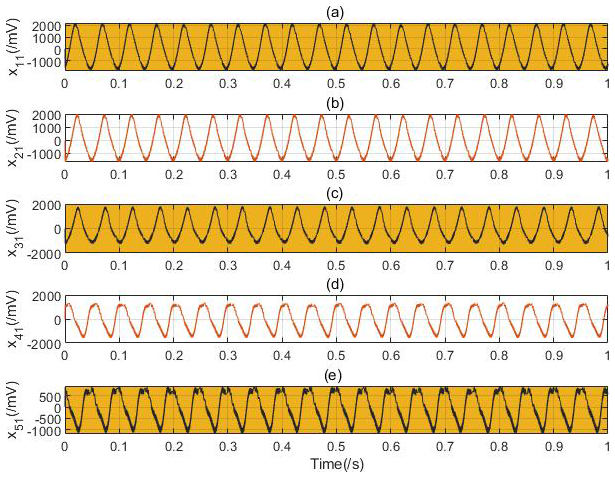
Figure 6Time-domain waveform of the five kinds of rub-impact faults without noise: (a) normal pattern with 0 g counterweight, (b) slight fault pattern with 0.9 g counterweight, (c) moderate fault pattern with 2.5 g counterweight, (d) severe fault pattern with 3.6 g counterweight, and (e) failure pattern with 5.0 g counterweight.
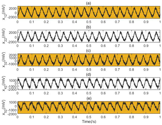
Figure 7Time-domain waveform of the five kinds of rub-impact faults with noise: (a) normal pattern with 0 g counterweight, (b) slight fault pattern with 0.9 g counterweight, (c) moderate fault pattern with 2.5 g counterweight, (d) severe fault pattern with 3.6 g counterweight, and (e) failure pattern with 5.0 g counterweight.
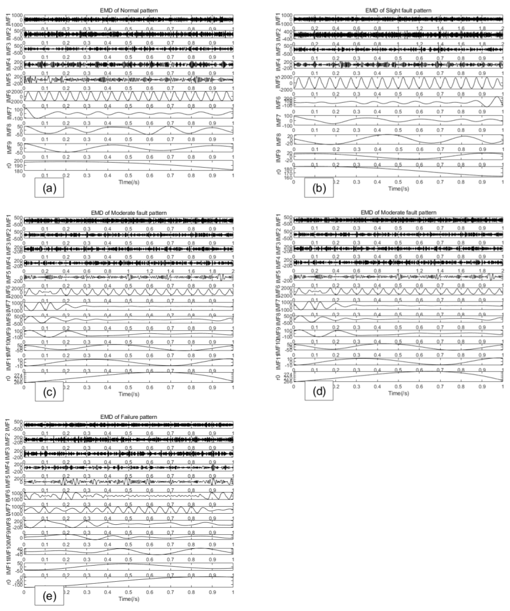
Figure 8IMF decomposition of five different fault patterns: (a) normal pattern, (b) slight rub-impact fault pattern, (c) moderate rub-impact fault pattern, (d) severe rub-impact fault pattern, and (e) failure rub-impact pattern.
3.2 Dynamic CNN
The dynamic CNN embeds dynamic learning in the traditional CNN model. Firstly, the dynamic trajectory is modeled with the reconstruction signals xp(t) and yp(t).
The RBF neural network identifier is constructed as in the following equation, Eq. (4):
where , is the estimation of Z, A is the gain of the identifier, W is the neural network weights, S(∗) is the radial basis function, the Gaussian RBF is employed (), is the center of the receptive field, and η is the width of the receptive field. u is the control input vector.
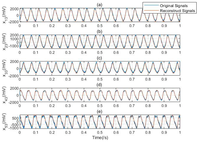
Figure 9The comparison of reconstructed signals based on PCC: (a) normal pattern with 0 g counterweight, (b) slight fault pattern with 0.9 g counterweight, (c) moderate fault pattern with 2.5 g counterweight, (d) severe fault pattern with 3.6 g counterweight, and (e) failure pattern with 5.0 g counterweight.
The weight update law is set as in Eq. (5).
where and σ is a small value.
Then, based on the identification theory of Wang and Chen (2011) and Lan et al. (2023), the fault dynamics can be obtained based on the RBF neural network identifier (Eq. 6).
where ξ is the practical approximation error and .
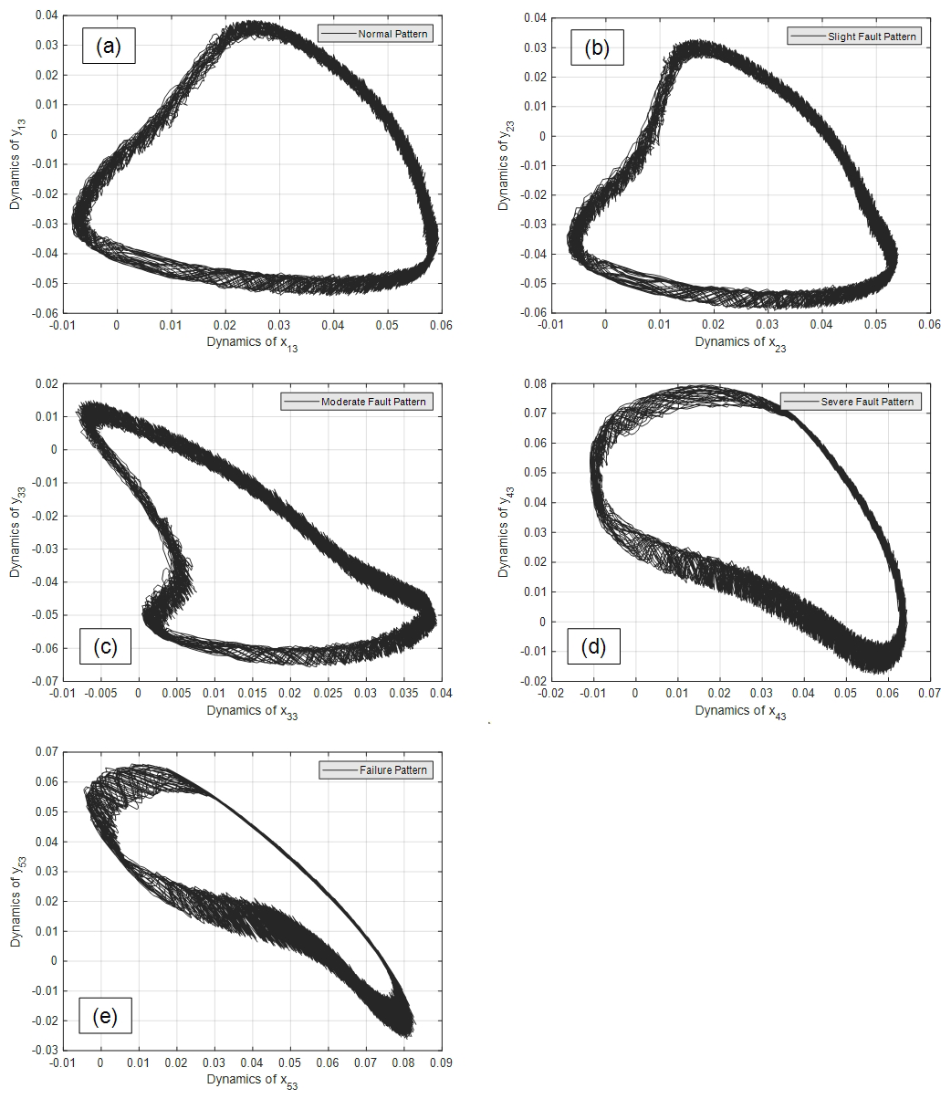
Figure 11Dynamics trajectories of the five kinds of rub-impact faults: (a) normal pattern, (b) slight rub-impact fault pattern, (c) moderate rub-impact fault pattern, (d) severe rub-impact fault pattern, and (e) failure rub-impact pattern.
After the convergence of the neural weight, the constant system fault dynamics trajectories are obtained based on the constant weights as in the following equation, Eq. (7).
where ξ0=O(ξ(t)) is the identification error and , , is the time segment of the weight convergence process. The obtained dynamics trajectories of rub-impact faults are stored with the identified results and denoted as the dynamics information. The fault dynamics information can provide more sensitive and distinct fault characteristics to the further diagnostic model. The dynamics trajectory image combined with the X direction and Y direction is denoted as F(xp(t))−F(yp(t)). The corresponding pixel size of those trajectories is 128 × 128.
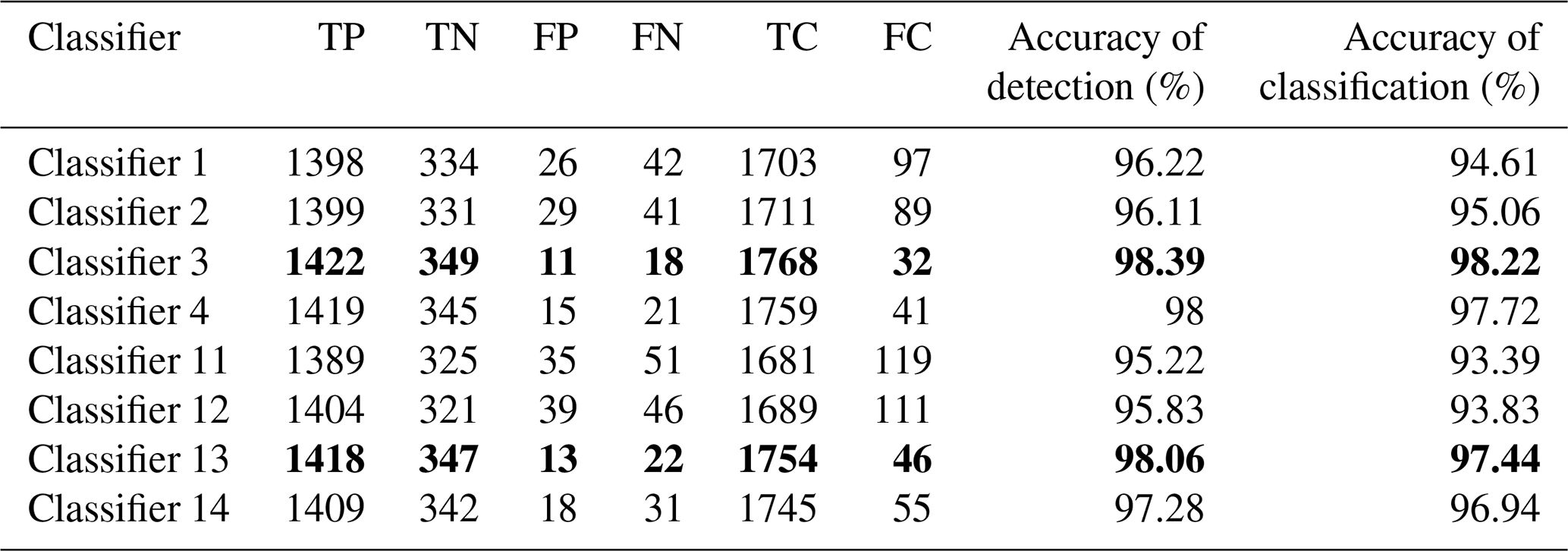
Table 4Diagnosis results of rotor rub-impact faults based on Experiment 1. The values in bold denote the experiment results of the proposed method.
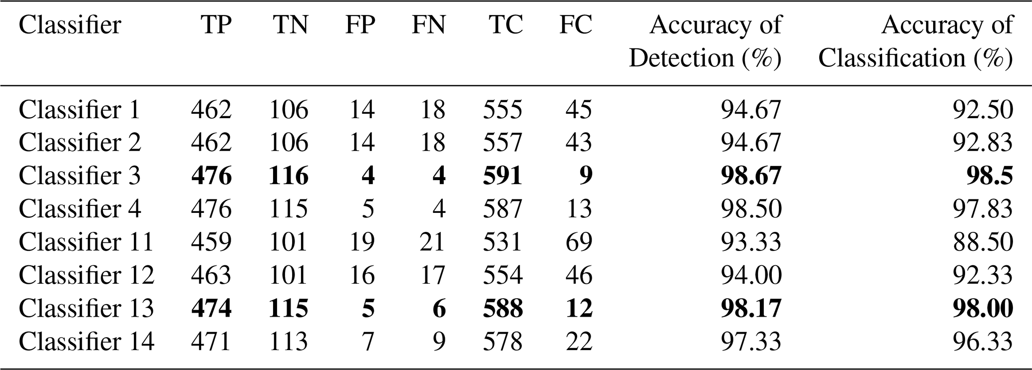
TP: the number associated with the accurate detection of rub-impact faults. TN: the number associated with the accurate detection of the healthy state. FP: total number of normal patterns – TN. FN: total number of rub-impact faults – TP. TC: the number associated with the accurate classification of rub-impact faults and normal patterns. FC: total number of all patterns – TC. Accuracy of detection = , and accuracy of classification = .
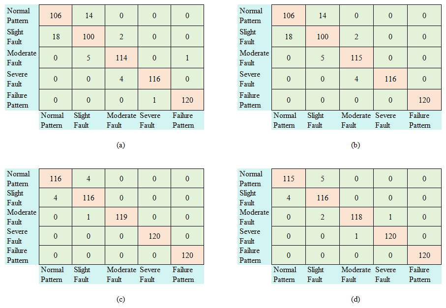
Figure 12Diagnosis results of Experiment 1 without noise (a) based on Classifier 1, (b) based on Classifier 2, (c) based on Classifier 3, and (d) based on Classifier 4.
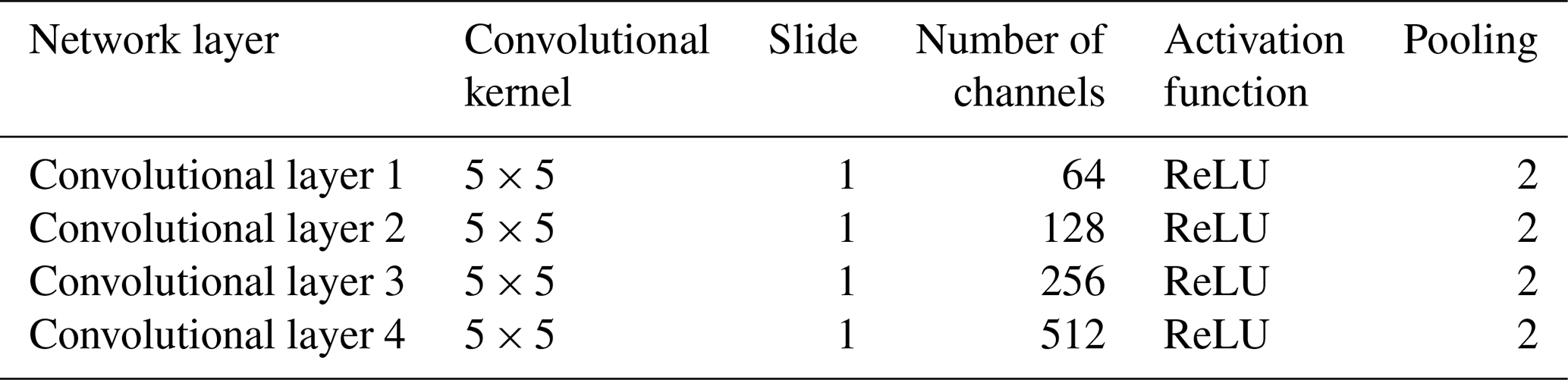
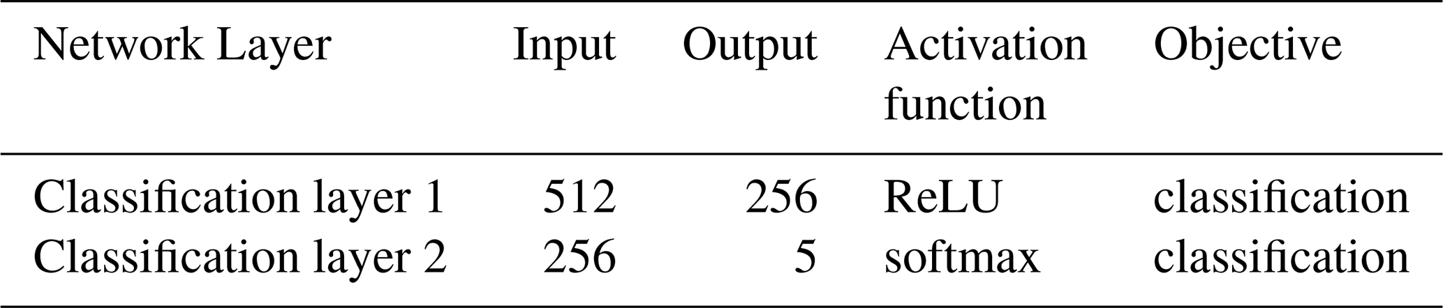
Due to the obtained highly discriminate dynamic image, the traditional CNN is selected as the training model. The CNN performs operations such as four multiple convolutions and pooling operations on the input signal to extract features from the original signal and form shared features, and then it uses two fully connected layers for specific fault detection tasks. The four multiple convolutional layers perform deep feature extraction on signals. The fully connected layer is responsible for mapping the features extracted by convolution to specific classification tasks. With the results of the experiments, the traditional CNN can be achieved very high diagnosis performance due to the priority property of the identified fault dynamics. Therefore, the traditional CNN architecture is used using less computing power and achieves good results.
The specific parameter settings for the convolutional layer and the fully connected layer are shown in Tables 1 and 2. Convolutional layers use convolutional kernels to convolve local regions of input data, with each kernel using the same weights to extract local features of input information and share weights. The ReLU is used as the activation function of the convolutional layer, and the softmax is employed in the Classification layer 2 of the full connection layer.

Figure 13Diagnosis results of Experiment 1 with noise (a) based on Classifier 11, (b) based on Classifier 12, (c) based on Classifier 13, and (d) based on Classifier 14.
3.3 The proposed diagnostic algorithm
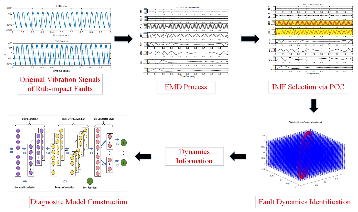
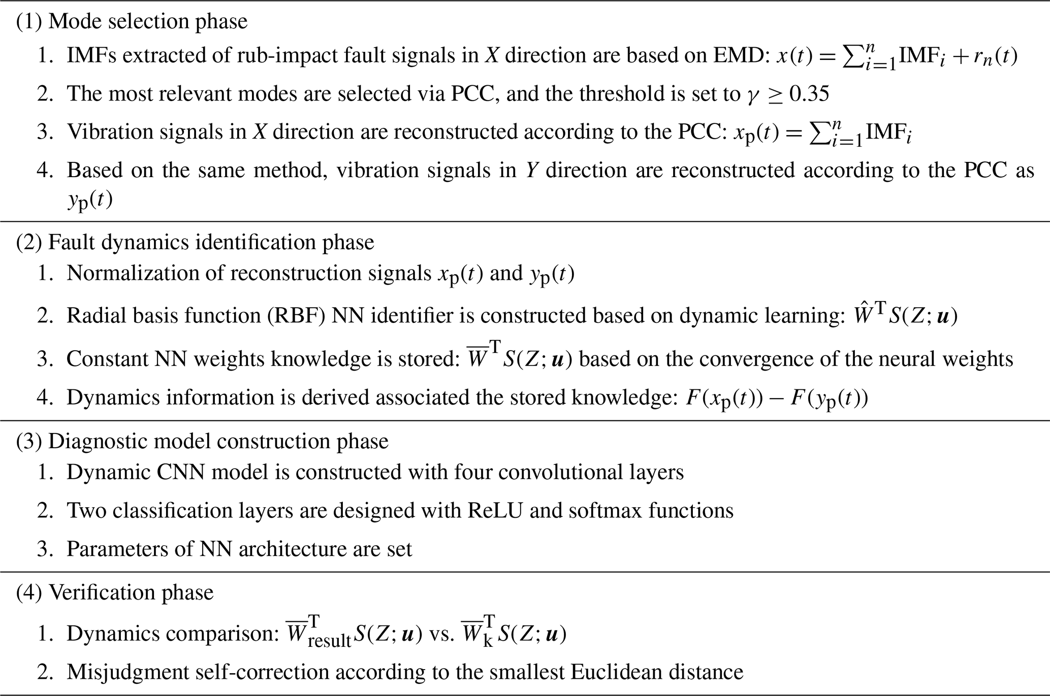
The diagnostic platform of the proposed method is shown in Fig. 3, and the detailed diagnostic algorithm is shown in Table 3. It includes four phases: the mode selection phase, the fault dynamics identification phase, the diagnostic model construction phase, and the verification phase.
In the mode selection phase, the sampled vibration signals in X and Y directions are analyzed based on EMD, and the different IMFs are derived. In order to obtain the more accurate diagnostic results, the most correlated IMF modes are selected according to the PCC. According to the new added experiment results, the threshold of the PCC process is set to γ≥0.35 in the process of rub-impact fault diagnosis. The vibration signals in X and Y directions are reconstructed as xp(t) and yp(t).
Table 5Diagnosis results with different threshold of PCC. The values in bold denote the selection threshold of the paper.
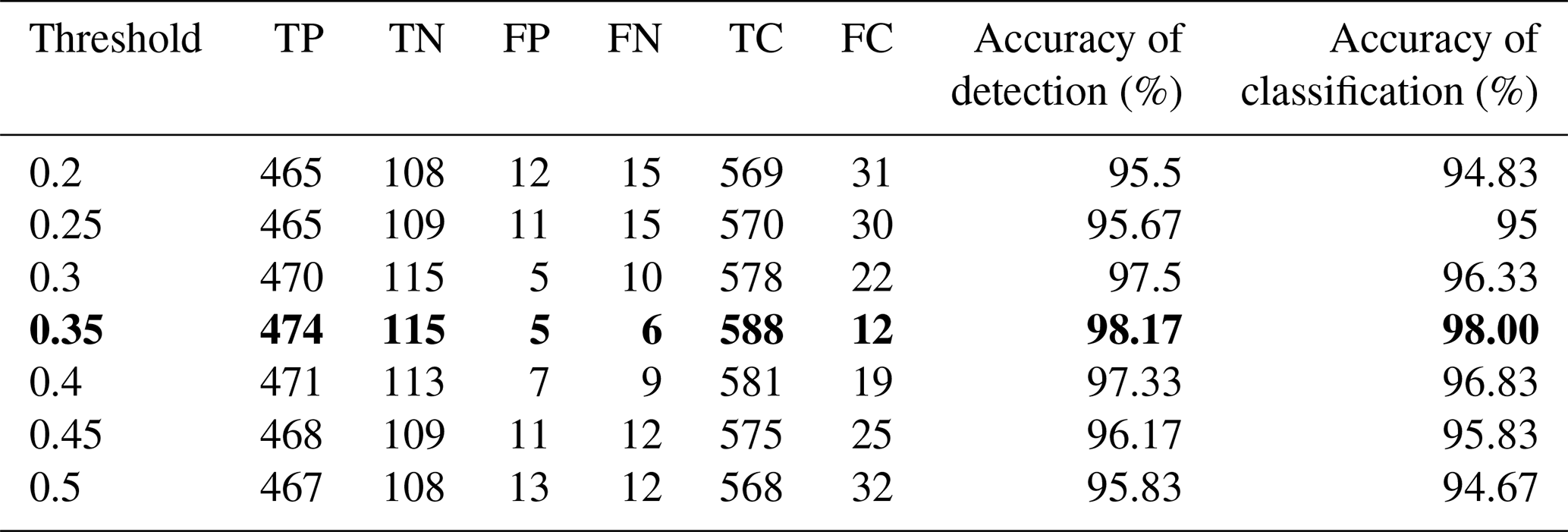
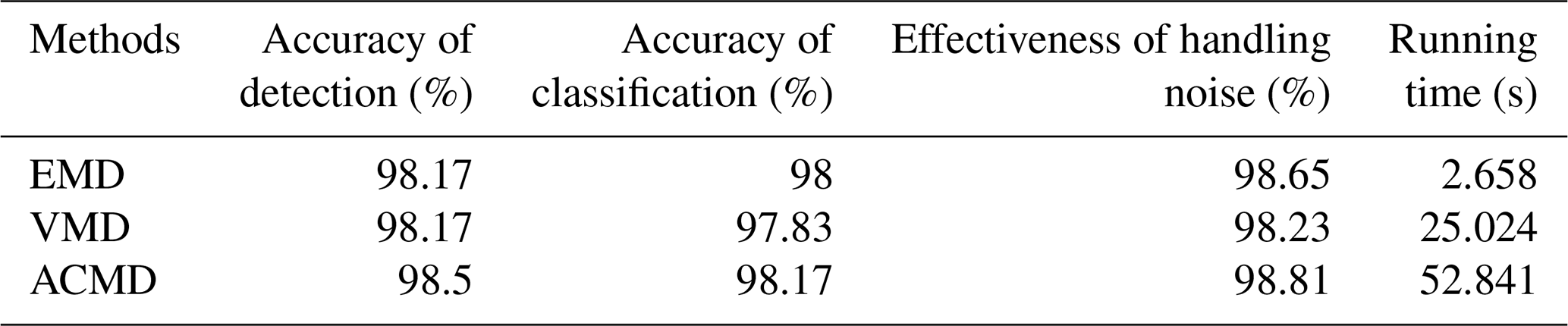
Table 6Diagnosis results with different time–frequency analysis methods.
In the fault dynamics identification phase, the reconstruction signals xp(t) and yp(t) are normalized, and the dynamic identifier is constructed using a RBF neural network. The selected IMF modes satisfy the condition of persistent excitation. Therefore, the local accurate identification can be obtained based on the dynamic learning mechanism. Most importantly, the learned dynamic knowledge can be stored in constant NN weights based on the convergence of the neural weights, and the dynamics trajectories are obtained in the form of images: F(xp(t))−F(yp(t)). In the diagnostic model construction phase, the learned dynamics trajectories images are fed into the CNN input layer. The dynamic CNN diagnosis model is constructed with four convolutional layers, and two classification layers are designed using ReLU and softmax functions.
In the last verification phase, the misjudgment self-correction is implemented by embedding the fault dynamics information, which increases the interpretation between the dynamic CNN diagnostic model significantly. Specifically, the misjudgment classification can be self-corrected based on the comparison of the fault dynamics, and the difference between the diagnosis result and the identified results are measured by the Euclidean distance. According to the smallest Euclidean distance, the difference between the misjudgment result and the correct result can be reflected via the fault dynamics changes.
where and N is the total number of training dataset. The corresponding smallest Euclidean distance Diffk can be achieved by comparing all the Diff values.
Additionally, in real-life applications, it should be pointed out that the threshold of the mode selection process and the parameters of the fault diagnosis model can be set based on the experiments associated with the baseline database. Besides, the mode selection and fault dynamics identification phase require less computing power and can be easily implemented, which makes the proposed diagnostic model very suitable for edge computing.
4.1 Datasets
The rub-impact experiment is implemented based on the rotor rubbing fault test rig as shown in Fig. 4. The test rig consists of a rotor motor, coupling, preamplifier, signal conditioner, eddy current sensor, unbalance device, collision and friction transposition, support frame, rotor shaft, and bearings. The motor is excited by a speed controller and drives the rotor shaft using a flexible coupling. The rotor shaft length in this test rig is 500 mm, and the diameter is 10 mm. The two eddy current sensors in the test rig are installed in the horizontal and vertical directions, respectively, to monitor the rotor shaft displacement caused by collision and friction faults in both directions. The sampling frequency in the experiment is set to 5.12 kHz, and the sampling time is 2 s. The fault experiments are implemented with three variable working conditions, and the corresponding motor speed is set to 1200, 1600, and 1800 rpm.
Table 7Diagnosis results of rotor rub-impact faults based on Experiment 2. The values in bold denote the experiment results of the proposed method.
The detailed rub-impact device is shown in Fig. 5. The rub-impact fault experiment is divided into five classes, and each class is obtained by embedding different counterweights, as shown in Fig. 5a and b. The counterweights associated with 0, 0.9, 2.5, 3.6, and 5.0 g are selected to be installed on the disk. The 0 g counterweight represent the healthy state (i.e., normal pattern), and the 0.9, 2.5, 3.6 and 5.0 g represent the slight degree, moderate degree, severe degree, and failure degree of the rub-impact faults. The rub block is fixed, and the rub-impact faults can be induced based on the unbalance force (Fig. 5c). As the weight of the counterweight increases, the unbalanced force will become greater, leading to an increasing degree of rub-impact fault. The two eddy current sensors in the test rig are installed in the horizontal and vertical directions (Fig. 5d), respectively, to monitor the rotor shaft displacement caused by rub-impact faults in X and Y directions. Each class of rub-impact fault is collected 100 samples with 10 240 data points, and the total number of the fault samples is 1500, associated with three different rotate speeds of 1200, 1600, and 1800 rpm. The training and testing datasets are set to be 6:4.
The time-domain waveform of five different kinds of rub-impact faults with and without noise are shown in Figs. 6 and 7 under the condition of 1800 rpm in the X direction. The raw vibration signals are relatively clean, and the Gaussian white noise is added to simulate real environmental conditions. x11, x21, x31, x41, and x51 represent the vibration normal pattern with 0 g counterweight, slight fault pattern with 0.9 g counterweight, moderate fault pattern with 2.5 g counterweight, severe fault pattern with 3.6 g counterweight, and failure pattern with 5.0 g counterweight, respectively. x12, x22, x32, x42, and x52 correspond to the presence of noise, as shown in Fig. 7.
According to the time-domain waveform under different weighting conditions, it can be seen that the time-domain waveform of the 0 g counterweight and 0.9 g counterweight are very similar. The most distinguishing features cannot be illustrated based on the time-domain features of original signals.
Table 8Diagnosis results with different working conditions (without noise). The values in bold denote the experiment results of the proposed method.
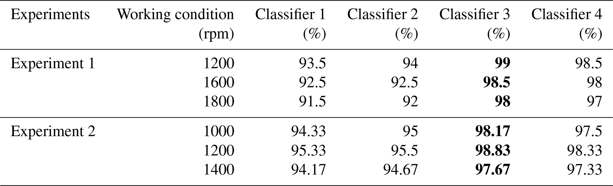
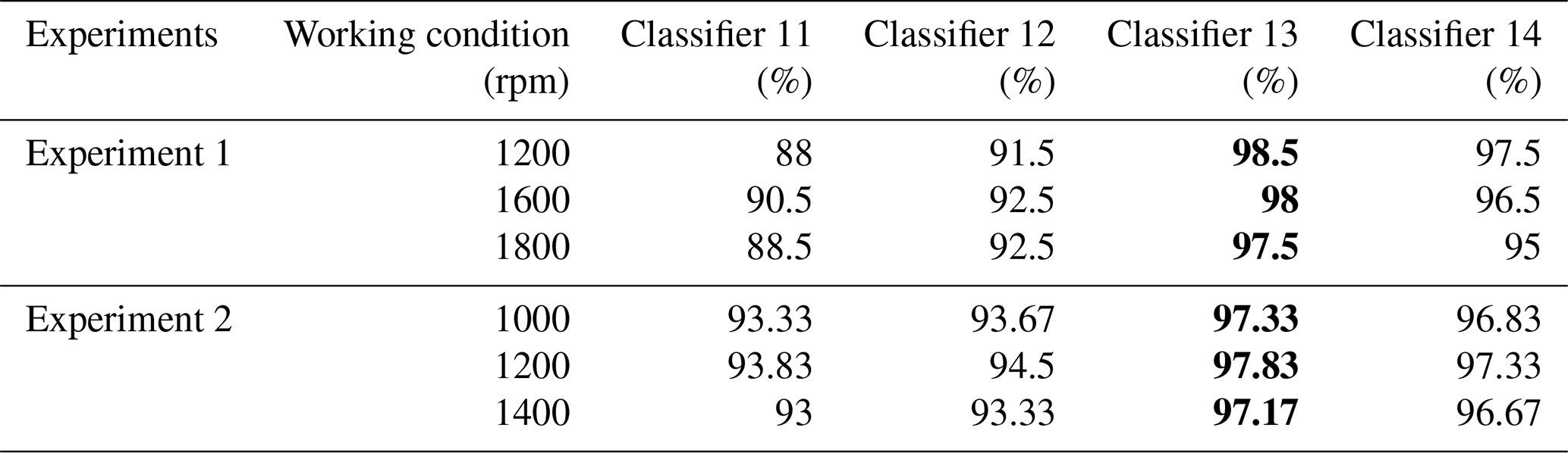
Table 9Diagnosis results with different working conditions (noise). The values in bold denote the experiment results of the proposed method.
4.2 Rub-impact fault diagnosis results
4.2.1 Experiment no. 1: small sample of rotor rub-impact fault experiment
First, based on the EMD method, the most correlated fault components are selected in the fault dynamics identification phase. The five different kinds of rub-impact fault are selected to show the decomposition process of the EMD in the X direction, especially in the noisy environment. IMFs of five different fault patterns can be obtained as shown in Fig. 8.
The correlated IMFs are selected based on the PCC with γ≥0.35, and the reconstructed vibration signals are shown in Fig. 9. It can be seen that the original signals are drowned out by noise signals, and the reconstructed signals associated with the selected IMFs can perfectly match the original signals of Fig. 9. Regarding the vibration signals in the Y direction, the EMD and PCC are implemented in the same way to obtain the reconstructed signals. x13, x23, x33, x43, and x53 represent the reconstructed vibration signals of the normal pattern, slight fault pattern, moderate fault pattern, severe fault pattern, and failure pattern in the X direction, respectively.
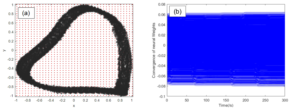
Based on the reconstructed signals, normalization is first performed for the accuracy of subsequent diagnosis. The neuron centers are evenly spaced within , the width is set to 0.05, and the total number of neural nodes is 1681. Furthermore, the parameters of the RBF identifier and update law are designed as , , and σ=0.001. Then, the fault dynamics can be identified based on dynamic learning, and the identified results indicated that the system dynamics can reflect the inner change in the rub-impact faults. To demonstrate the identification process, the severe rub-impact fault is selected to illustrate the RBF architecture and the convergence of NN weights. The corresponding results are shown in Fig. 10. The dynamics trajectories of five rub-impact faults can be obtain based on the constant weights as shown in Fig. 11. y13, y23, y33, y43, and y53 represent the reconstructed vibration signals of the normal pattern, slight fault pattern, moderate fault pattern, severe fault pattern, and failure pattern in the Y direction, respectively.
In Fig. 10, the red dots represent neural neurons of RBF network, and the vibration signals of the system are normalized in the X and Y directions. it can be seen that the convergence performance of neural network weights has reached stability. Therefore, the dynamics trajectories can be stored based on the convergence of the weights. In the classification stage without noise, the proposed method is compared with three other different methods according to the idea of ablation experiment.
The four classifiers are denoted as follows: Classifier 1 is related to the time-domain signals + CNN, Classifier 2 is related to time-domain signals + EMD + CNN, Classifier 3 is related to the proposed dynamic CNN method (i.e., the time-domain signals + EMD + dynamics trajectories + CNN), and Classifier 4 is related to the time-domain signals + EMD + dynamics trajectories + support vector machine (SVM). Correspondingly, Classifier 11, Classifier 12, Classifier 13, and Classifier 14 are defined in the noisy environment. The confusion matrix of diagnostic results with and without noise is shown in Figs. 12 and 13, and the detailed diagnostic result statistics are shown in Table 4.
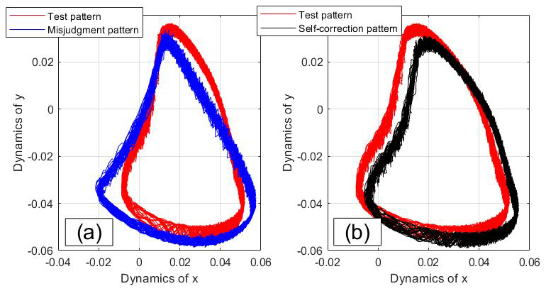
In the verification phase, the misjudgment (Fig. 14a) and self-correction (Fig. 14b) of slight rub-impact faults as shown in Fig. 14 in the mixing-matrix result with Classifier 13. Six slight rub-impact faults are recognized as the normal pattern. In order to analyze the misjudgment results, the self-correction mechanism is illustrated based on the fault dynamics comparison. According to the smallest Euclidean distance, the self-correction is illustrated in Fig. 14b. It can be seen that one of the misjudgment slight rub-impact faults has been re-identified as the correct pattern. The dynamics comparison of the system rub-impact faults can greatly increase the interpretability of the diagnostic process.
Furthermore, in order to evaluate the threshold, different values of γ with a step of 0.05 are checked based on Experiment 1. The values of γ are set to 0.2, 0.25, 0.3, 0.35, 0.4, 0.45, and 0.5. The corresponding results are illustrated in Table 5. This experiment is implemented based on Classifier 13 under the condition of the noisy environment.
Based on Table 5, the best diagnosis results are obtained when the threshold γ is set to 0.35. Therefore, γ≥0.35 is employed in the diagnosis algorithm as shown in Table 3. Additionally, to compare the effectiveness of the employed EMD method, the latest VMD (Xia et al., 2025) and ACMD (Ding and Wang, 2022) are chosen to verify diagnosis performance. For the sake of fairness in comparison, it is worth noting that the threshold is set to the same value in the mode selection phase. The fault dynamics identification phase and the diagnostic model construction phase remain unchanged. Based on the proposed diagnosis model (i.e., Classifier 13 in the noisy environment), the diagnosis results with the signal decomposition of EMD, VMD, and ACMD are presented in Table 6. The effectiveness of handling noise presents the correlation degree between the reconstructed signal and the original.
In Table 6, even though the accuracy classification of the diagnosis model with ACMD is slightly higher than those with EMD, the running time of EMD has been significantly reduced and requires the least amount of computing power compared to other time–frequency analysis methods. Therefore, taking into account edge computing in practical applications, the EMD is chosen as the fault component decomposition and can handle the noise.
4.2.2 Experiment No. 2: large-scale sample of rotor rub-impact fault experiment
To further validate the effectiveness of the proposed diagnostic model, a large-scale rotor rub-impact fault experiment has been conducted and denoted as Experiment 2. Three new working conditions (i.e., 1000, 1200, and 1400 rpm) are implemented, and each class of rub-impact fault collects 500 samples with 10 240 data points. The total number of fault samples is 7500, associated with three different rotate speeds of 1000, 1200, and 1400 rpm. 300 samples are randomly selected from each class to participate in training and testing, and the training and testing datasets of a total of 4500 samples are set to 6:4. Based on the proposed method, the diagnostic results of Experiment 2 without and with noise are shown in Table 7.
Additionally, in order to verify the effectiveness of the proposed method more clearly in each working condition, the classification diagnosis results of six working conditions based on Experiment 1 and Experiment 2 are shown in Table 8 (without noise) and Table 9 (with noise). Based on Tables 7–9, it can be concluded that the proposed diagnosis model can achieve the best diagnostic performance under different working conditions. This phenomenon proves that dynamic CNN has better adaptability to different fault working conditions of rotor systems.
In this paper, a new rotor rub-impact fault diagnosis method is proposed. The most correlated fault components are extracted using EMD, and the dynamics information is achieved based on dynamic learning. Then, the obtained dynamic trajectories can be embedded in system dynamics and state information, and are taken as the input of the CNN model. Experiment 1 shows that the proposed method can obtain the more better diagnosis performance compared with the traditional methods and that it has achieved the highest diagnosis accuracy of 98.5 % without noise and 98 % with noise. In addition, the generalization ability and adaptability of the dynamic CNN model have been verified based on Experiment 2. Future research can expand the proposed method to other rotor fault diagnosis in multiple noisy environments. The research results of this article can provide a new fault diagnosis idea for rotating machinery, which has important theoretical significance and engineering application value.
The rub-impact fault dataset can be requested from the corresponding author.
JS: conceptualization and writing (original draft preparation). RZ: data curation and analysis. QW: methodology and writing (review and editing).
The contact author has declared that none of the authors has any competing interests.
Publisher's note: Copernicus Publications remains neutral with regard to jurisdictional claims made in the text, published maps, institutional affiliations, or any other geographical representation in this paper. While Copernicus Publications makes every effort to include appropriate place names, the final responsibility lies with the authors. Views expressed in the text are those of the authors and do not necessarily reflect the views of the publisher.
The author thanks the editors and reviewers for their efforts.
This work was partly supported by the China Post doctor Science Foundation (grant no. 2023M730726) and partly supported by the Science and Technology Research Project of Henan Province (grant no. 252102221013).
This paper was edited by Liangliang Cheng and reviewed by three anonymous referees.
Arifin, M., Wang, W., and Uddin, M.: An enhanced empirical mode decomposition technique for rotor fault detection in induction motors, IEEE T. Instrum. Meas., 74, https://doi.org/10.1109/TIM.2025.3551988, 2025.
Chen, L., Dong, L., Wu, Z., Fan, C., Shi, Wei., Li, H., Hua., R., and Dai, C.: ResNet diagnosis of rotor faults in oil transfer pumps, Heliyon, 10, https://doi.org/10.1016/j.heliyon.2024.e36170, 2024.
Ding, C. and Wang, B.: Sparsity-assisted adaptive chirp mode decomposition and its application in rub-impact fault detection, Measurement, 188, https://doi.org/10.1016/j.measurement.2021.110539, 2022.
Hou, Y., Cao, S., and Kang, Y.: Study on the frequency modulation phenomenon in the rotor system with blade-casing rub-impact fault, Int. J. Nonlin. Mech., 159, https://doi.org/10.1016/j.ijnonlinmec.2023.104626, 2024.
Jin, M., Wang, A., Wang, Q., and Wang, L.: Rub-impact dynamic analysis of the central tie rod rotor-blade-casing coupling system with the hirth couplings connection, J. Vib. Eng. Technol., 12, 1479–1503, https://doi.org/10.1007/s42417-023-00921-9, 2023.
Kou, H., Shi, Y., Du, J., Zhu, Z., Zhang, F., Liang, F., and Zeng, L.: Rub-impact dynamic analysis of a rotor with multiple wide-chord blades under the gyroscopic effect and geometric nonlinearity, Mech. Syst. Signal Process., 168, https://doi.org/10.1016/j.ymssp.2021.108563, 2022.
Lan, L., Liu, X., and Wang, Q.: Fault detection and classification of the rotor unbalance based on dynamics features and support vector machine, Meas. Control., 56, 1075–1086, https://doi.org/10.1177/00202940221135917, 2023.
Lei, Y., Lin, J., He, Z., and Zuo., M.: A review on empirical mode decomposition in fault diagnosis of rotating machinery, Mech. Syst. Signal Process., 35, 108–126, https://doi.org/10.1016/j.ymssp.2012.09.015, 2013.
Li, H., Zhang, Z., Li, T., and Si, X.: A review on physics-informed data-driven remaining useful life prediction: Challenges and opportunities, Mech. Syst. Signal Process., 209, https://doi.org/10.1016/j.ymssp.2024.111120, 2024.
Li, X., Xu, Y., Liu, J., Liu, J., Pan, G., and Shi, Z.: Dynamic modelling of a floating spline-coupling shaft system with parallel misalignment and tooth backlash, Mech. Syst. Signal Process., 226, https://doi.org/10.1016/j.ymssp.2025.112363, 2025.
Li, H., Zhang, Z., Li, T., and Si, X.: A review on physicsinformed data-driven remaining useful life prediction: Challenges and opportunities, Mech. Syst. Signal Process., 209, https://doi.org/10.1016/j.ymssp.2024.111120, 2024b.
Li, Y., Zhu, Z., Wen, C., Liu, K., Luo, Z., and Long, T.: Rub-impact dynamic analysis of a dual-rotor system with bolted joint structure: Theoretical and experimental investigations, Mech. Syst. Signal Process., 209, https://doi.org/10.1016/j.ymssp.2024.111144, 2024a.
Liu, D, Xiao, Z., Hu, X., Zhang, C., and Malik, O.: Feature extraction of rotor fault based on EEMD and curve code, Measurement, 135, 712–724, https://doi.org/10.1016/j.measurement.2018.12.009, 2019.
Liu, D., Cui, L., and Wang, H.: Rotating machinery fault diagnosis under time-varying speeds: A review, IEEE Sens. J., 23, 29969–29990, https://doi.org/10.1109/JSEN.2023.3326112, 2024.
Miao, M. and Yu, J.: Deep feature interactive network for machinery fault diagnosis using multi-source heterogeneous data, Reliab. Eng. Syst. Saf., 242, https://doi.org/10.1016/j.ress.2023.109795, 2024.
Prosvirin, A., Islam, M., and Kim, J.: Rub-Impact fault diagnosis using an effective IMF selection technique in ensemble empirical mode decomposition and hybrid feature models, Sensors, 18, https://doi.org/10.3390/s18072040, 2018.
Prosvirin, A., Piltan, F., and Kim, J.: Hybrid rubbing fault identification using a deep learning-based observation technique, IEEE T. Neur. Net. Lear., 32, 5144–5155, https://doi.org/10.1109/TNNLS.2020.3027160, 2020.
Prosvirin, A., Maliuk, A., and Kim, J.: Intelligent rubbing fault identification using multivariate signals and a multivariate one-dimensional convolutional neural network, Expert. Syst. Appl., 198, https://doi.org/10.1016/j.eswa.2022.116868, 2022.
Saini, K., Dhami, S., and Vanra, j.: Predictive monitoring of incipient faults in rotating machinery: a systematic review from data acquisition to artificial intelligence, Arch. Comput. Method. E., 29, 4005–4026, https://doi.org/10.1007/s11831-022-09727-6, 2022.
Shi, C., Ma, Y., Chen, X., Song, Z., and Hong, J.: Research on coupled angular-torsional vibration of unbalanced rotor, Mech. Syst. Signal Process., 234, https://doi.org/10.1016/j.ymssp.2025.112808 112808, 2025.
Wang, C. and Chen, T.: Rapid detection of small oscillation faults via deterministic learning, IEEE T. Neural. Net., 22, 1284–1296, https://doi.org/10.1109/TNN.2011.2159622, 2011.
Wang, Q. and Wang, C.: Incipient fault detection of nonlinear dynamical systems via deterministic learning, Neurocomputing, 313, 125–134, https://doi.org/10.1016/j.neucom.2018.06.001, 2018.
Wang, Q., Wu, W., Zhang, F., and Wang, X.: Early Rub-impact Fault Detection of Rotor Systems via Deterministic Learning, Control. Eng. Pract., 124, https://doi.org/10.1016/j.conengprac.2022.105190, 2022.
Wang, S., Cheng, C., Zhou, J., Qin, F., Feng, Y., Ding, B., Zhao, Z., and Chen, X.: Reassignment-enable reweighted sparse time-frequency analysis for sparsity-assisted aeroengine rub-impact fault diagnosis, Mech. Syst. Signal Process., 183, https://doi.org/10.1016/j.ymssp.2022.109602, 2023.
Xia, X., Wang, X., and Chen, W.: A hybrid fault diagnosis model for rolling bearing with optimized VMD and fuzzy dispersion entropy, Int. J. Rotating Mach., 1, https://doi.org/10.1155/ijrm/7990867, 2025.
Xu, Y., Liu, J., Li, X., and Tang, C.: An investigation of vibrations of a flexible rotor system with the unbalanced force and time-varying bearing force, Chem. Soc. Rev., 38, https://doi.org/10.1186/s10033-025-01186-x, 2025.
Yang, Y., Zhang, Y., Zeng, J., Ma, H., Yang, Y., and Cao, D.: Insight on uncertainty of geometrically nonlinear rotor with rub-impact under maneuvering motion, J. Sound Vib., 570, https://doi.org/10.1016/j.jsv.2023.118018, 2024.
Yu, B. and Xie, C.: A convolutional neural-network-based diagnostic framework for industrial bearing, Mech. Sci., 15, 87–98, https://doi.org/10.5194/ms-15-87-2024, 2024.
Yuan, Z., Zhang, L., and Duan, L.: A novel fusion diagnosis method for rotor system fault based on deep learning and multi-sourced heterogeneous monitoring data, Meas. Sci. Technol., 29, https://doi.org/10.1088/1361-6501/aadfb3, 2018.
Zhu, Z., Lei, Y., Qi, G., Chai, Y., Mazur, N., An, Y., and Huang, X.: A review of the application of deep learning in intelligent fault diagnosis of rotating machinery, Measurement, 206, https://doi.org/10.1109/ACCESS.2019.2963092, 2023.