the Creative Commons Attribution 4.0 License.
the Creative Commons Attribution 4.0 License.
 | 17 Oct 2025
Research on the meshing load-bearing characteristics of the micro-textured thermoelastic hydrodynamic lubrication interface for a warship PRTS
Jiafu Ruan
Yongmei Wang
Weiqiang Zou
Gears are subjected to external excitation from alternating loads, and the micro-textured meshing interface (MTMI) will share larger contact stresses during the warship power rear transmission system (PRTS) torsional process. The current elastoplastic interface load-bearing contact model ignores the time-dependent changes in the textured element micro-convex peak (MCP) base diameter, which is usually regarded as a certain constant value, and which is extremely inconsistent with the time-varying characteristics of the MCP matrix diameter of actual MTMI, leading to deviation of the load-bearing analytical values determined by the current contact model from actual data. A generalised thermoelastic hydrodynamic lubrication (TEHL) contact load-bearing model with interface micro-texture (IMT) is proposed, where the contact area between all MCPs across the MTMI is represented by the equivalent scale factor parameter and the shape distribution density function is modified to ensure that the MCP is solved integrally. A mathematical model of meshing anti-scuffing load-bearing capacity (ASLBC) in a TEHL steady state is derived to reveal the correlation between contact stiffness and damping of the meshing MTMI under the influence of alternating loads, which provides a theoretical basis and data reference for homogeneous interface enriched lubrication (IEL) effect improvement and meshing ASLBC enhancement of the contact IMT for the PRTS.
- Article
(4630 KB) - Full-text XML
- BibTeX
- EndNote


A micro-textured gear unit is the warship power rear transmission system (PRTS), a high-speed and heavy-duty gear transmission system for large warships, as shown in Fig. 1 (Source: National Key Research and Development Program Project, Grant No. 2023YFB3406301). The excellent lubrication and load-bearing regulation of the micro-textured meshing interface (MTMI) have been well recognised, and the teeth surface micro-texture seems to be a penalty area for gears, which is attributed to the traditional perception of similarity between meshing interface micro-pitting and texturing units (Özdemir et al., 2017; Liu et al., 2020; Guilbault and Lalonde, 2019). The gear surface micro-texturing is applied to the interface to modulate time-varying meshing stiffness and enhance the lubrication enrichment effect, thereby improving meshing load-bearing performance (Croccolo et al., 2020). The current elastoplastic interface load-bearing contact model ignores the time-dependent changes in the base diameter of the texturing micro-convex peaks (MCP), which is usually recognised as a constant value, and which is extremely inconsistent with the time-varying characteristics of the base diameter of the MCP elements in the actual MTMI, thus leading to the deviation of the load-bearing resolved values determined by the current contact model from the actual data.
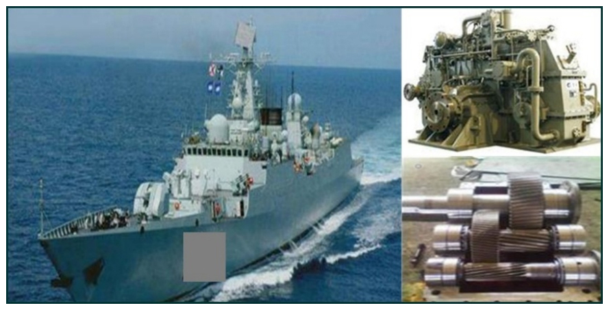
Figure 1A high-speed and heavy-duty gear transmission system for large warships (Source: National Key Research and Development Program Project, Grant No. 2023YFB3406301).
As the core component for torque transmission, gears possess diverse sizes, high load-bearing capacity, and high efficiency, which are of vital importance in determining the reliability and accuracy of the PRTS (Tu et al., 2021; Marques et al., 2021). In the case of a PRTS operating under special environments, it is confronted with extreme usage conditions such as high and low temperatures, deep-sea pressure, strong acids and alkalis, and other extreme conditions of use. The maximum pressure in the deep sea reaches over 200 to 300 MPa, which is 2000 to 3000 times that of atmospheric pressure. The marine environment brings challenges such as acid and alkali corrosion to the PRTS.
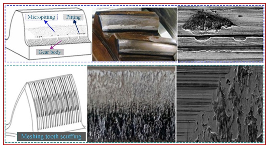
Figure 2Contact fatigue and scuffing affecting load-bearing capacity arising from the use of deep-sea gears (Source: MPRD, Grant No. MG20220203).
The deep-sea gearbox is exposed to alternating environments of high temperature, high humidity, high salt fog and seawater spray for a long time in the alternating environment, which causes serious electrochemical corrosion problems. Deep-sea gears are subjected to contact fatigue and scuffing affecting load-bearing capacity in service, as shown in Fig. 2 (Source: MPRD, Grant No. MG20220203). High-end equipment requires gears with greater load-bearing capacity and serviceability, and controlling the load-bearing capacity of deep-sea gears has become critical. Although advanced processing technologies such as surface hardening and precision machining improve the gear load-bearing capacity, they still cannot meet the ever-increasing service life and load-bearing capacity requirements, and frequent equipment accidents caused by insufficient gear strength are common, which makes the gear load-bearing capacity become a key bottleneck restricting the performance and reliability of the PRTS.
The gear directly affects the overall performance of the PRTS. The meshing domain, where the frictional heat causes a sharp increase in teeth surface temperature, leads to the rupture of the interfacial oil film layer and consequently lubrication failure. This results in rigid contact between the metal MTMI, an increase in the friction coefficient between the teeth surfaces and a rapid rise in the instantaneous contact temperature of the meshing interfaces. The gear profile and the lubrication state between the teeth surfaces change, and the metal teeth surfaces are torn off along the high-speed sliding direction, resulting in scuffing load-bearing failure (Chen et al., 2021, 2023; Zhao et al., 2022a). Even short-term overloading, improper lubrication or excessive temperature rise causes serious damage to the teeth profile and further deteriorates the lubrication state between the meshing interfaces. Considering the harsh real-time working conditions of warship PRTSs, gear damage and failure often occur or originate from the microscopic interface of the teeth surfaces. Scuffing load-bearing fatigue of the MTMI frequently leads to gear lubrication failure. Traditional design methods, which are based on Hertzian contact theory and assumptions such as smooth surfaces, no lubrication, isothermal elastohydrodynamic lubrication and homogeneous elastic materials, are no longer capable of accurately predicting the lubrication characteristics and load-bearing performance of gears in warship PRTSs. Therefore, it is necessary to deeply explore the evolution of lubrication characteristics in heavily loaded line contact interfaces and the correlation mechanism with the load-bearing performance of MTMI. This will provide a scientific basis and theoretical reference for enhancing the thermoelastic hydrodynamic lubrication (TEHL) characteristics of the meshing interfaces under real-time full working conditions of the PRTS and for accurately assessing the anti-scuffing load-bearing capacity (ASLBC) of the MTMI.
The warship PRTS is a high-speed and heavy-load gear transmission system. The MTMI are typically in a mixed lubrication state characterised by the coexistence of boundary and thin-film fluid lubrication (Cheng et al., 2024; Sánchez et al., 2019; Černe et al., 2024). The state cannot generate a sufficient lubricating film to completely separate the MTMI. This is especially true under high dynamic operating conditions or during start–stop operations, where the characteristics of the MTMI have a significant impact on lubrication behaviour and load-bearing capacity. The meshing pair interface consists of two parts: direct contact of the MCP and the load-bearing capacity of the TEHL film (Wang et al., 2022; Chang et al., 2023; Yang et al., 2023). The contact morphology interface micro-texture (IMT) is a new idea and method for analysing the scientific issues related to gear lubrication and load-bearing capacity in warship PRTSs. The lubrication and load-bearing effects in the meshing time domain process are not negligible (Cao et al., 2024; Zhang et al., 2025). The key technology is that the appropriate IMT can generate a coupling effect of “secondary enrichment lubrication” and “micro-hydrodynamic load-bearing”. However, the heat flux generated by alternating friction of the MTMI causes a significant increase in teeth temperature, which in turn alters the stable state mechanism of the warship PRTS meshing interface TEHL (Ammosov et al., 2020; Zhao et al., 2022b). This includes multi-scale parameters such as IMT lubrication enrichment characteristics, time-varying thermoelastic deformation, transient thermal expansion, thermomechanical coupling of the stress structure, interface morphology IMT configuration characteristics and distribution density (Li et al., 2025).
In the field of warship PRTS research, an urgent and critical scientific issue that needs to be explored is how to reasonably design the IMT of the MTMI under real-time full operating conditions to improve the interface enriched lubrication (IEL) characteristics and enhance the key performance of the ASLBC. It is also essential to construct a universal mathematical model for mixed lubrication of the MTMI, simulate and solve the core variables, and verify and calibrate them through full operating condition experiments. This research aims to reveal the mechanism of the IEL effect of mixed TEHL meshing IMT and optimise the multi-scale parameter design of the microelement configuration. Additionally, it seeks to explore the influence of mechanisms and patterns of the geometric characteristics and directional parameters of the MTMI on IEL properties in order to improve the ASLBC to adapt to the high contact line loads during the alternating meshing time domain. The research on the IEL mechanism and ASLBC of the mixed TEHL meshing IMT is of great theoretical significance and practical application value for the development of the tribodynamics of the MTMI in high-speed and heavy-load gear transmission systems.
2.1 Constructing an interface load-bearing contact model based on fractal theory
The MTMI of the warship PRTS is in continuous contact, and the actual micro-contact area is much smaller than the macroscopic theoretical meshing domain area. This research is based on the meshing IMT fractal theory and investigates the temporal variation of single micro-convex peaks (MCPs) within the load-bearing contact domain, unveiling the evolving trends of actual contact changes in MCPs on non-macroscopically smooth interfaces. The mathematical relationship between the actual contact interface domain and the true MTMI loads is determined by solving the distribution density function of the differential MCP elements using integration. Figure 3 illustrates the mathematical model of the correlation between height deformation and individual differential MCP element protrusions on the MTMI. The MCP elements deform transiently under the cyclic excitation loads on the textured interface, considering the different heights of the MCP elements and the different loads, and the true deformation values of the MCP elements are limited within the range of 0−δ. The teeth profile of the meshing gear pair of a single MCP element within the contact interface domain is usually approximated by a cosine function (with the single base length set as l). Based on the description of the three-dimensional profile characteristics of the MTMI using a bivariate function (Codrignani et al., 2020; Wang et al., 2023; Meng et al., 2019), it is expressed as
where z(x,y) represents the height function of the three-dimensional textured interface profile (the profile height of a single MCP element); G is the amplitude of the height of the MCP elements of the MTMI; D represents the fractal dimension; φ denotes a constant value that is not less than 1.0; and ϕm,n denotes a uniformly distributed random phase within the interval [0, 2π], generated by a random number generator. Its role is to ensure that the frequency components of the meshing interface profile do not spatially overlap. h is the sampling profile length of the MTMI (the diameter of the base of a single MCP element); M represents the number of superimposed ridgelets used to construct the surface profile morphology, the specific value of which can be determined based on the power spectrum of the imaged surface morphology; n is the distribution index of a random frequency of the interface profile; and nmax is the random phase when the interface profile is uniformly distributed.
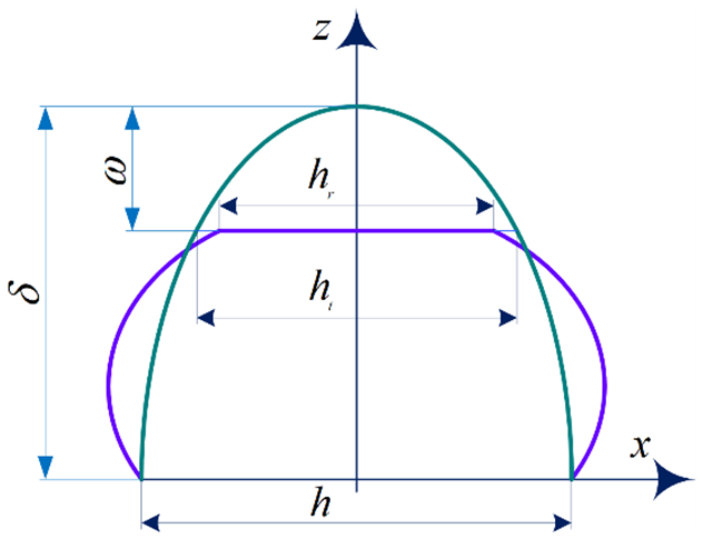
Figure 3Mathematical model of the correlation between height deformation and individual MCP element protrusions on the MTMI.
As illustrated in Fig. 3, when the MCPs of the textured contour are subjected to the interface normal contact pressure, the actual deformation height of the MCPs is designated as ω, the distance between the apex of the MCP and its base is defined as δ, the base diameter of the MCP is represented as h, the transverse contour diameter is denoted as ht, the actual contour diameter is hr, and the transverse contact area a of a single MCP is described as
where ρ represents the radius of curvature of a single MCP, thereby allowing the calculation of the radius of curvature at position x=0 of the MCP (see Expression 2).
Based on the actual textured interface contact area and combined with related thermo-elastoplastic deformation studies (Rajput et al., 2021; Galda et al., 2019; Liu et al., 2020), it is demonstrated that when the textured interface is subjected to external alternating excitation loads, it inevitably coexists with a single MCP at the critical stage of elastic deformation. The critical deformation amount ωl of a single MCP is expressed as (Wang et al., 2021)
where E represents the base material comprehensive elastoplastic modulus and holds true, with ν1,2 denoting Poisson's ratio. K describes the correlation coefficient between the hardness value and the yield strength σy.
By combining Eqs. (2) and (4), ωl is described as
The critical contact area al of the cross-section of a single MCP is expressed as
According to the classical Hertz contact theory, the elastic contact load PE(ω) of a single MCP subjected to alternating excitation loads leading to elastoplastic deformation is expressed as (Petare et al., 2019)
By combining Eqs. (2) and (4) and substituting Eq. (8), we obtain
2.2 Single MCP load-bearing contact model
The aim is to establish the correlation between each MCP and its maximum peak value in order to achieve an integrable solution for the total elastic load of all MCPs across the entire contact area of the textured interface. Set the maximum MCP contact base diameter of the textured interface as Hmax, and let Hmax t represent the maximum truncated diameter of the MCP profile. By considering the cosine expression of the height profile of the MCP, the formula for the maximum value of the MCP profile is obtained as follows:
Considering the maximum micro-unit peak contact base diameter Hmax of the textured interface and combining it with the calculation formula for the contact area of the micro-unit peaks, the actual bearing contact area of the textured interface is expressed as
where aH represents the contact area of the textured interface with the maximum MCP contact base diameter Hmax and the contact area of the remaining micro-unit peaks is indirectly calculated using Hmax t.
By introducing the contact equivalent proportionality factor , Expression (3) is transformed into
From the above equation, it is concluded that the contact area of micro-unit peaks with different morphological scales can necessarily be obtained by the corresponding equivalent proportionality factor εb, that is, holds true.
Thus, the base diameter h of each micro-unit peak is expressed as (Xing et al., 2021)
By substituting the above equation into Eq. (9), the elastic contact load PE(ω) caused by the elastoplastic deformation of a single micro-unit peak under alternating excitation loads can be solved (Rosenkranz et al., 2019):
Let , where χ represents the correlation function with the contact equivalent proportionality factor εb. By simplifying the above Eq. (14), we obtain
2.3 Micro-unit peak morphology distribution density function correction model
In the alternating meshing region of the warship PRTS, the teeth surface contact area with the micro-unit peak morphology distribution cannot accurately reflect the actual IMT contact area. Based on the fractal model, the contact distribution characteristics of the MCP are described in the form of a micro-unit density function, which is expressed as
where represents the contact area of the maximum micro-unit peak base diameter Hmax and J(α) is the distribution density function of the non-curved surface contact area.
Considering the curvature variation characteristics of non-flat interfaces, their contact area will also change accordingly, as shown in Fig. 4. Unlike the distribution density model of non-curved surface contact areas, the curved surface contact area is not less than α, and the number of micro-unit peaks decreases, meaning the total number does not exceed . By introducing the curved micro-unit peak contact coefficient εJand deriving the spherical interface contact area distribution formula J(α), the initial area distribution density function J′(α) is further corrected (Wos et al., 2020).
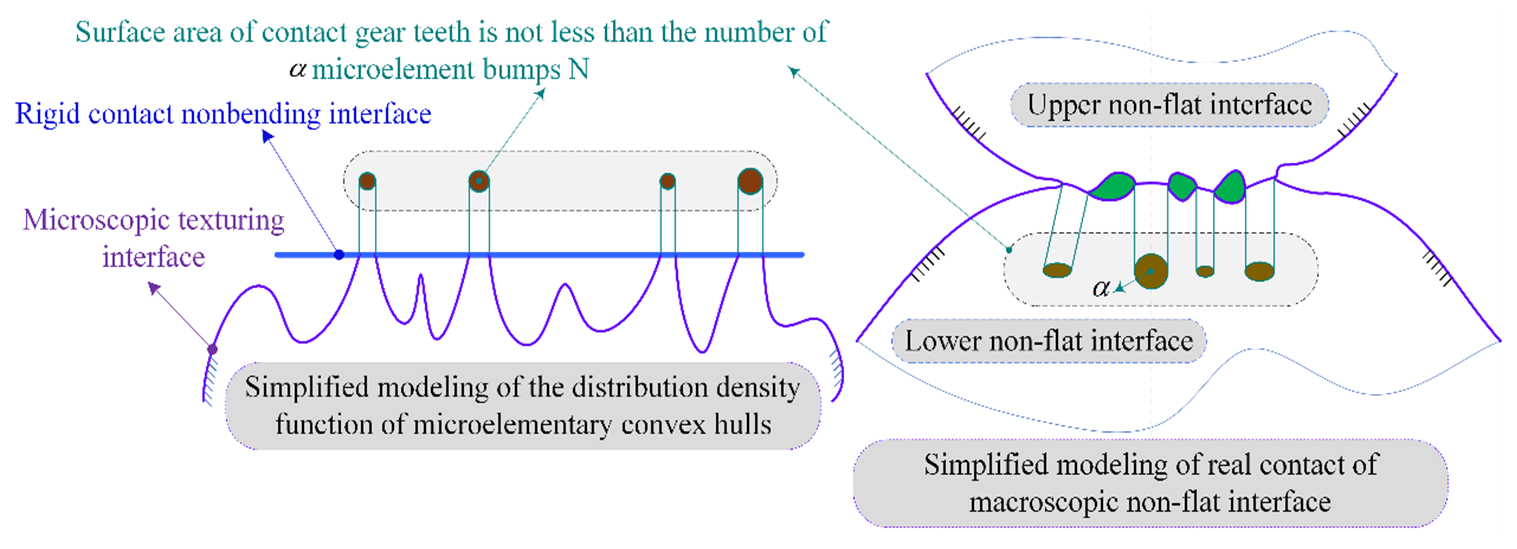
Figure 4Schematic contact morphology of microelementary peaked bodies at a nonplanar texture interface.
The curved surface microelementary peaked body contact coefficient , where SL represents the theoretical non-flat interface contact area; here, holds, with B1 and B2 denoting parameters related to the geometric characteristics of the non-flat interface morphology. F represents the contact width of the microelement convex peak body. Ω(F,E) represents a function related to the interface material (parameter E) and its contact form (parameter F), and C represents the normal contact load between the interfaces. ∑Sn represents the total contact area of any number of non-flat interfaces, and its expression is (where the plus sign indicates external meshing and the minus sign indicates internal meshing). K0 represents the comprehensive curvature parameter, and exists, with X1 and X2 denoting the principal curvatures of the normal cross-section of the upper non-flat interface and X3 and X4 denoting the principal curvatures of the normal cross-section of the lower non-flat interface.
3.1 Analysis of contact teeth surface stiffness and damping
Based on the transient process of gear meshing in the warship PRTS, and considering the textured interface contact model, the multi-scale parameter correlation of the TEHL textured interface is determined to analyse the time-varying meshing load-bearing characteristics (i.e. meshing stiffness and viscous damping characteristics) (Sivayogan et al., 2022; Gupta et al., 2022). Figure 5 shows the geometric parameter analysis model of an involute gear with textured interface meshing contact, aiming to determine the characteristic parameters of the textured interface and the analytical parameters of lubrication properties at key meshing positions during the alternating contact process of the teeth surface. This model is used to solve the contact stiffness and viscous damping of the meshing interface.
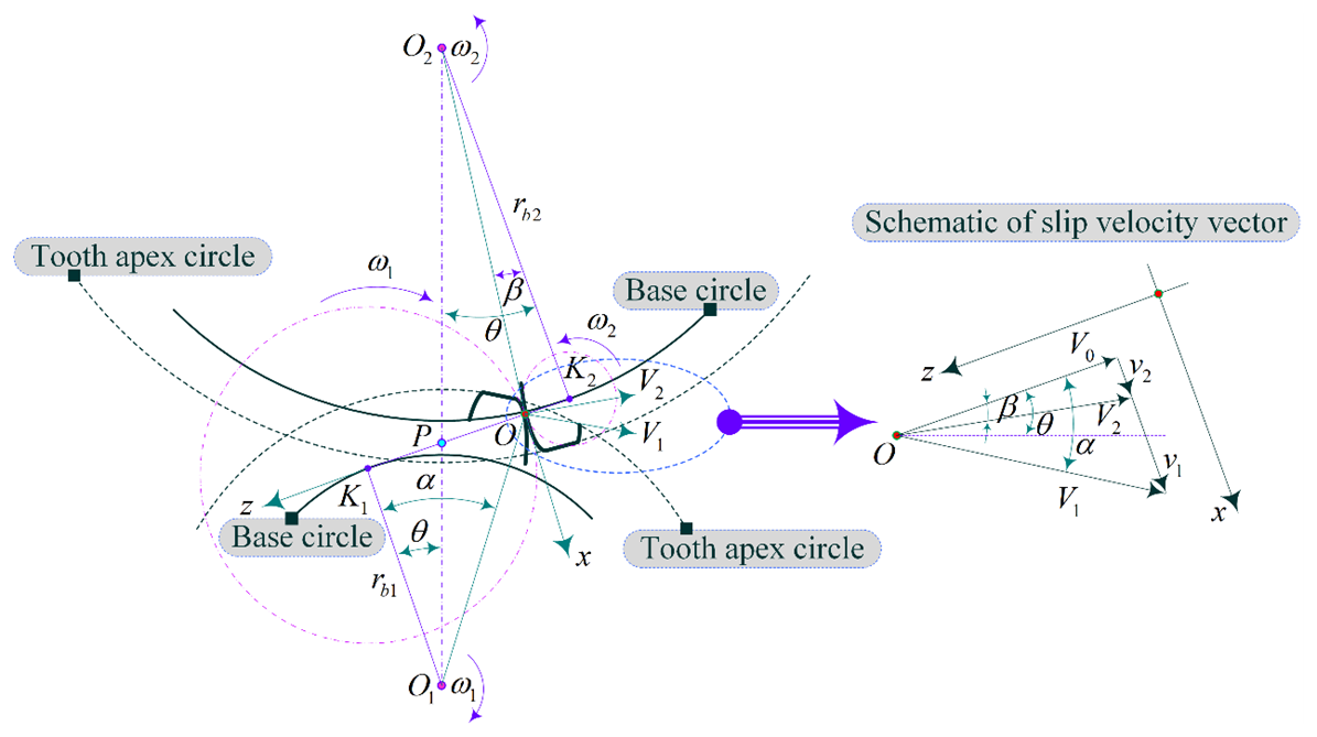
Figure 5Geometric parameter analysis model of textured interface meshing contact involute gear.
The time-varying key parameters during the meshing process are the meshing dynamic force, sliding velocity and radius of curvature. Point O represents any contact position on the teeth profile of the meshing surface. V1 and V2 are the velocities of the pinion and gear at the position of point O, respectively. Points O1 and O2 are the geometric centres of the pinion and gear, respectively. Line K1K2 represents the common tangent of the base circles. rb1 and rb2 are the base circle radii of the two gears, respectively. α and β are the meshing rotation angles of the two gears, respectively. The radius of curvature at the contact point O is expressed as
where the equivalent radius of curvature at the meshing point is . Given the rotational speeds of the two gear shafts as n1 and n2, the tangential velocity at the meshing point on the teeth surface is expressed as
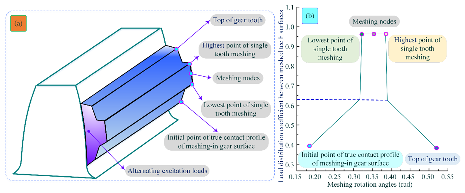
Figure 6Variation of the load distribution coefficient of the MTMI. (a) Time-varying load of the meshing interface. (b) Relation of the load distribution coefficient with the rotation angle.
Under alternating excitation loads, the meshing teeth surfaces are in a time-varying contact state, and the load borne during the transmission process originates from multiple meshing teeth. This leads to the exploration of the load distribution law among the meshing teeth surfaces (Kaneta et al., 2022). The variation curve of the load distribution coefficient between the meshing teeth surfaces of the warship PRTS is shown in Fig. 6. The load distribution coefficient at the initial point of the actual contact profile of the meshing teeth surface is the smallest, with two teeth participating in the meshing state. In the double-teeth contact (DTC) region, the load between the teeth surfaces increases and exhibits a linear distribution growth. The double-teeth meshing ends when a single tooth enters the initial meshing state. From the lowest point to the highest point of single-tooth meshing, only one pair of teeth bears the steady-state load, and the meshing node is located in the middle of the single-tooth contact (STC) region. The end of the single-tooth meshing state marks the beginning of the meshing-in of a new tooth pair (i.e. the double-teeth meshing state), and the meshing process terminates at the tooth tip. During this transient process, the load between the meshing teeth surfaces decreases and exhibits a linear trend.
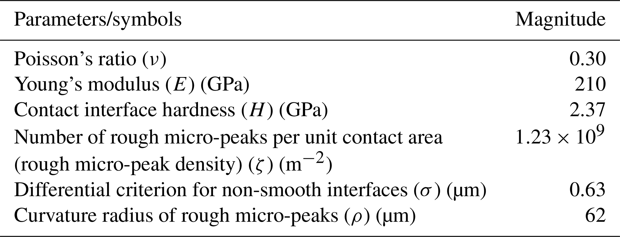
Based on the proposed TEHL analytical model, the contact stiffness and damping of the meshing tooth surface interface are solved. Using the gear parameters provided in Table 1 as research data, the influence of the slip velocity and alternating load factors on the contact stiffness and damping of the meshing interface is explored. The variations in tooth surface contact stiffness and damping under different meshing interface slip velocities are analytically determined, as shown in Fig. 7.
As shown in Fig. 7, as the slip velocity at the meshing interface increases, the contact stiffness and damping of the tooth surface exhibit a decreasing trend. When the meshing region transitions from the single-tooth contact (STC) domain to the double-teeth contact (DTC) domain, the contact stiffness and damping of the tooth surface undergo a sudden step-like change. Specifically, the contact damping initially increases and then decreases, while in the meshing-in STC region, the contact stiffness shows a decreasing rather than an increasing trend. When the DTC transitions back to the STC, the contact stiffness and damping of the tooth surface sharply decrease, reaching a minimum point, after which they gradually increase and then decrease again, forming a local minimum within a specific range.
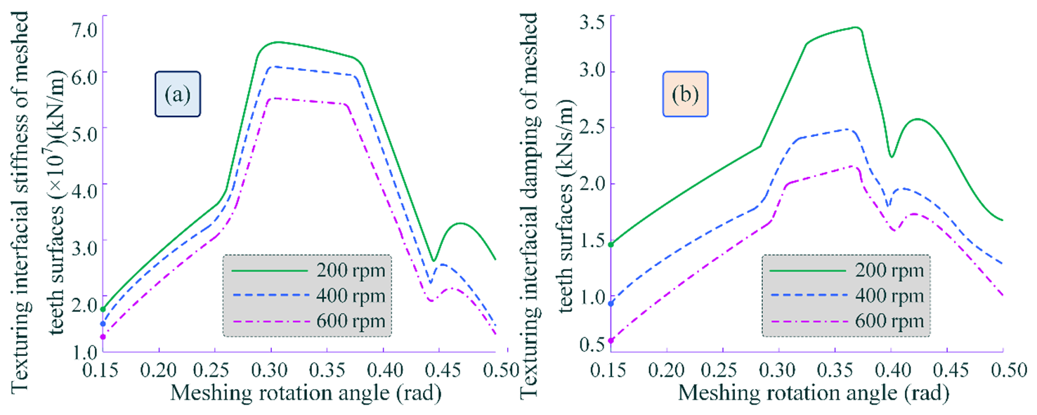
Figure 7Time-varying contact stiffness and damping of the MTMI under different slip velocities are illustrated as follows: (a) time-varying stiffness characteristics of the MTMI and (b) time-varying damping behaviour of the MTMI.
This phenomenon can be explained as follows: when the relative slip velocity between the transient interfaces of the meshing tooth surfaces approaches 0, the hydrodynamic fluid film becomes extremely thin, and the contact area of the micro-peaks increases. As a result, the influence of the micro-peaks dominates the contact stiffness and damping. Generally, the direct contact stiffness of the tooth surface is much smaller than the stiffness of the hydrodynamic fluid film. Moreover, a decrease in the slip velocity of the tooth surface leads to an increase in the amplitude of time-varying fluctuations in the contact stiffness and damping of the meshing interface.
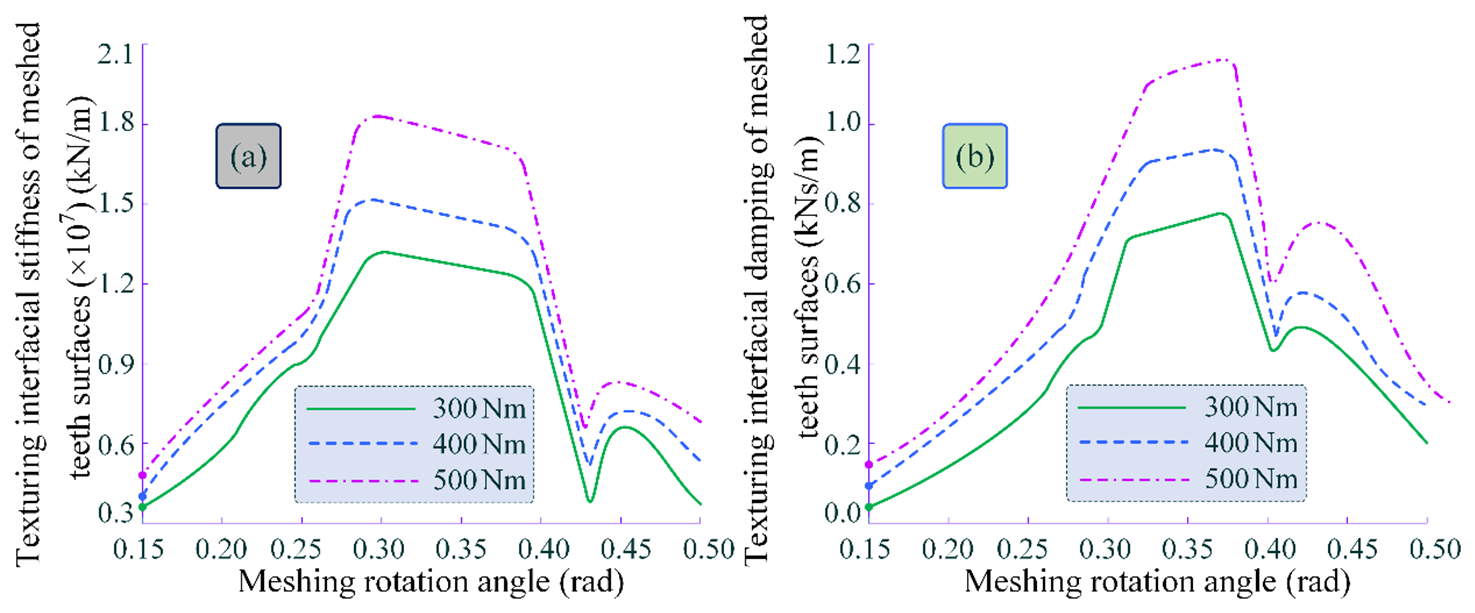
Figure 8Time-varying contact stiffness and damping of the MTMI under different interface loads. (a) Time-varying stiffness of the MTMI. (b) Time-varying damping of the MTMI.
The variations in tooth surface contact stiffness and damping under different meshing interface loads are analytically determined, as shown in Fig. 8. From the figure, it can be observed that as the meshing interface load increases, the tooth surface contact stiffness and damping also increase. Similar to the influence of slip velocity on tooth surface contact stiffness and damping, the time-varying trends of both stiffness and damping are nearly identical under varying loads. Compared to the effects of slip velocity, the influence of different meshing interface loads on tooth surface contact stiffness and damping is more consistent, with similar amplitude fluctuations. This indicates that the distribution characteristics of the hydrodynamic fluid film and its thickness dominate the values of tooth surface contact stiffness and damping. Furthermore, within the meshing domain, the distribution of hydrodynamic film pressure and film thickness has a more significant impact on slip velocity.
3.2 Analytical solution for tooth surface meshing stiffness and interface contact damping
Based on the aforementioned numerical analysis of tooth surface contact stiffness and damping, combined with the initial contact tooth surface meshing stiffness and damping, the tooth surface meshing stiffness and interface contact damping under TEHL conditions are further solved. The influence of slip velocity and alternating load on the variation trends of tooth surface meshing stiffness and interface contact damping is analysed. The time-varying patterns are illustrated in Fig. 9. As shown in the figure, when the slip velocity increases, the interface meshing stiffness and damping decrease. The variation amplitude of the interface meshing stiffness is less pronounced compared to the significant fluctuations in damping. Additionally, abnormal fluctuations in amplitude are observed during the transition between STC and DTC, or at the initial meshing-in and meshing-out stages. The transition from DTC to STC intensifies the time-varying damping, and during the alternating stages of STC and DTC, the slip velocity decreases, accompanied by a reduction in damping and large amplitude fluctuations.
Figure 10 illustrates the time-varying relationship between the interface meshing stiffness and damping under different tooth surface loads.
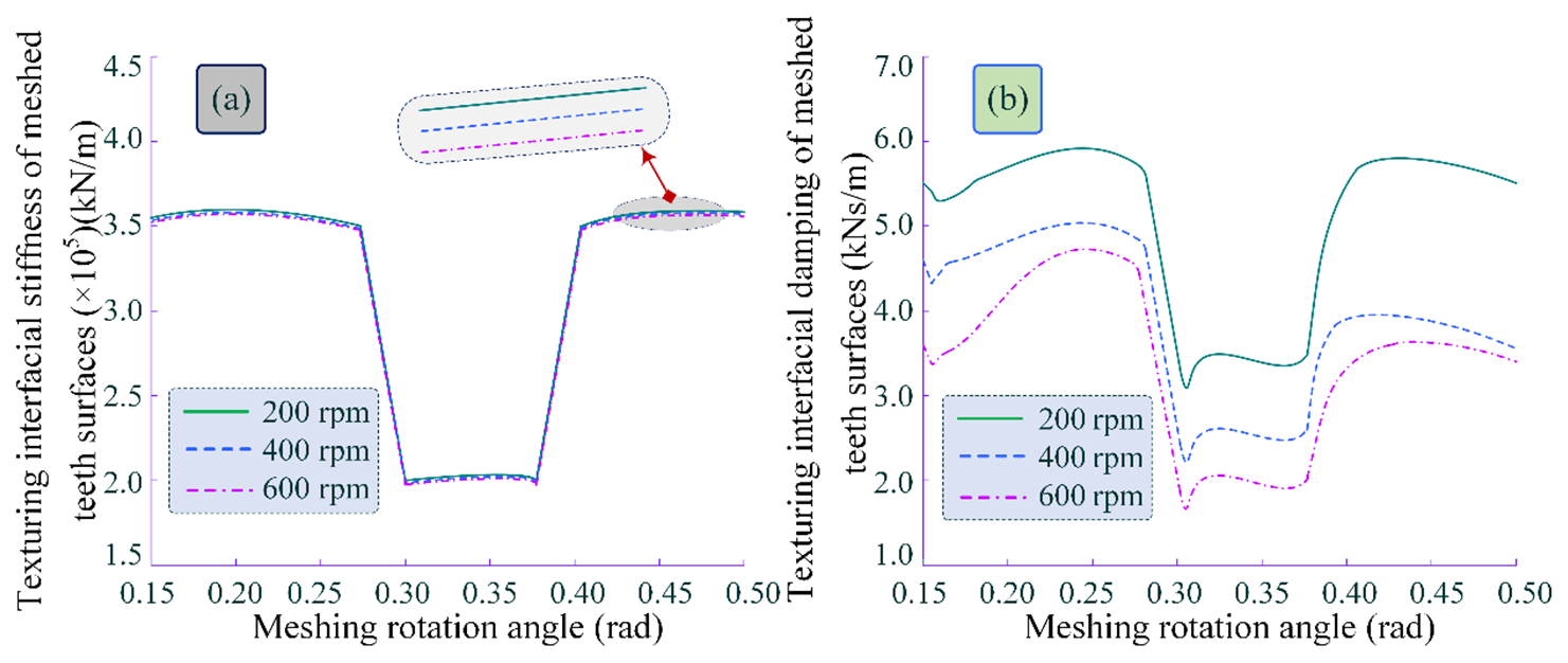
Figure 9Meshing time-varying stiffness and damping of different slip velocities. (a) Time-varying interface meshing stiffness. (b) Time-varying interface meshing damping.
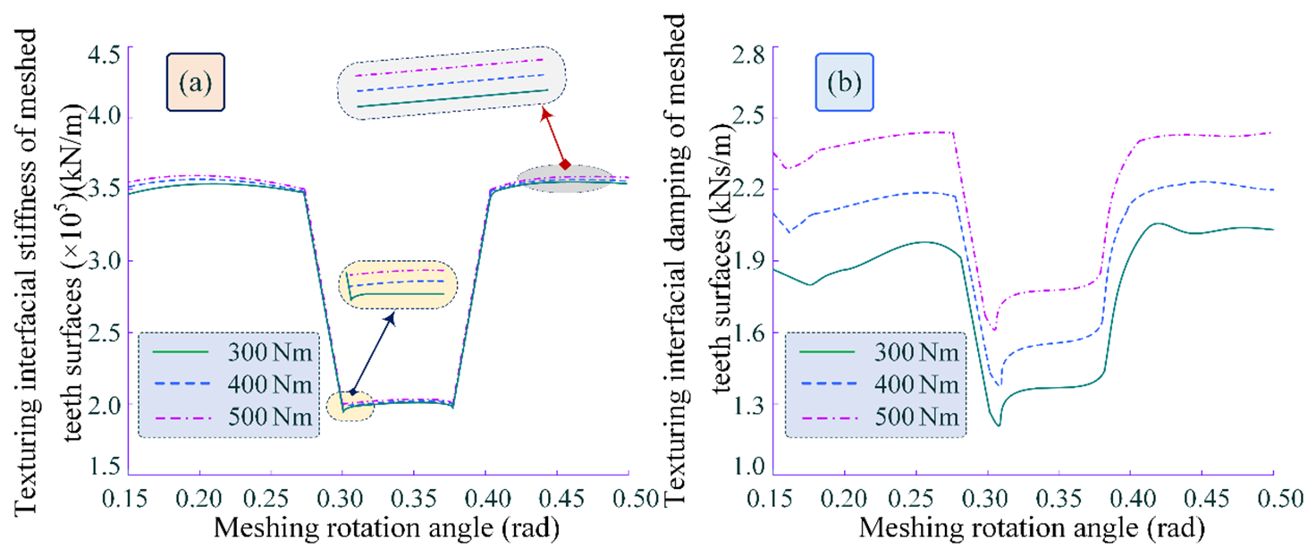
Figure 10Meshing time-varying stiffness and damping of different loads. (a) Time-varying interface meshing stiffness. (b) Time-varying interface meshing damping.
As shown in the figure, as the load on the tooth surface increases, the time-varying meshing stiffness and damping of the interface also increase. Compared to the results of the slip velocity analysis, the variation amplitude of the meshing stiffness and damping exhibits larger and more pronounced fluctuations. Particularly in Fig. 10a, when the meshing region transitions from the DTC to the STC, a sudden change in meshing stiffness occurs.
This change becomes more significant as the tooth surface load decreases, which is attributed to the reduction in meshing stiffness under TEHL conditions. Additionally, meshing damping is significantly influenced by the tooth surface load. During the alternating transition between STC and DTC (or at the initial meshing-in and meshing-out stages), the amplitude of damping shows abnormal fluctuations, as depicted in Fig. 10b. When transitioning from DTC to STC, the interface meshing damping undergoes a sudden change, and the amplitude variation trends under different teeth surface loads are almost similar. Overall, the time-varying patterns of interface meshing damping under different tooth surface loads are generally consistent, with only slight differences observed in the time-varying trends within the DTC region.
Under TEHL conditions, modifications such as profile fitting optimisation or edge trimming are often performed along the meshing length direction of the tooth surface interface to reduce and suppress the stress concentration. Additionally, considering the finite length of the actual contact line on the meshing tooth surface, these meshing characteristics will influence the analysis of the contact interface ASLBC.
Considering the characterisation parameters of surface textures, the equations for contact load and contact area for the MTMI are derived. The influence of material parameters, friction coefficients and peak amplitudes of MCP bodies on the normal stiffness, viscous damping and ASLBC of the meshing interface is analysed. The intrinsic relationship between the microscopic morphology of textures and the load-bearing characteristics of meshing tooth surfaces is established. Based on the derived mathematical model of textured interface contact and the simulation using MATLAB, the time-varying trends of the ASLBC under different texture parameters are revealed. This approach aims to determine the optimal texture parameters, thereby guiding the design of micro-textured patterns on meshing teeth surfaces to enhance the operational stability and service life of warship PRTSs under alternating and complex working conditions.
4.1 Simulation analysis of the influence of fractal dimension on meshing load-bearing performance
Considering different fractal dimensions D and using MATLAB simulations, the relationship between the textured tooth surface load and the actual interface contact area within the meshing region is analysed.
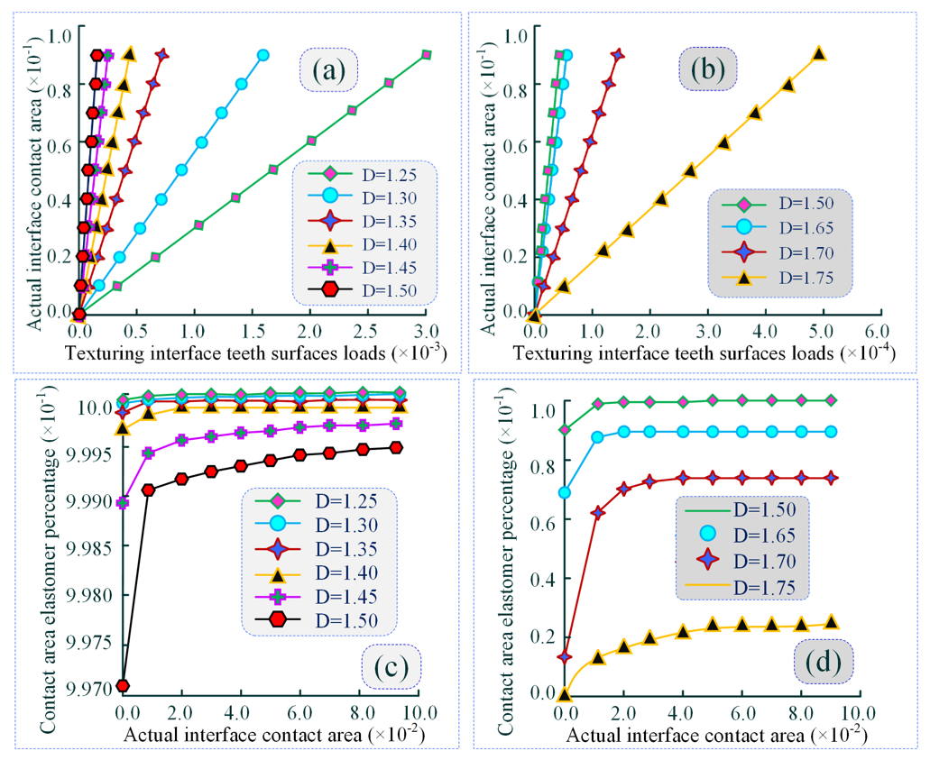
Figure 11Correlation law between textured surface loads and actual interfacial contact area in meshing domains with different fractals. (a), (b) Effect of actual interface contact area on load characteristics variation of textured surface. (c), (d) Time-varying trend of elastomer share of contact area in meshing domains.
As shown in Fig. 11a, under the same meshing load, as the contact interface area increases, the unit micro-area decreases, and the load-bearing capacity of the tooth surface improves. The results indicate a proportional linear relationship between the textured tooth surface load and the actual interface contact area. The analysis also reveals that as the fractal dimension D increases, the slope of the variation curve gradually rises and reaches its maximum at fractal dimension D=1.50, thereby demonstrating that the textured tooth surface exhibits optimal ASLBC at this fractal dimension. From Fig. 11b, it can be observed that at fractal dimension D>1.50, if the slope of the variation curve shows a declining trend, it indicates the existence of an optimal constant value for this fractal dimension. Specifically, when the fractal dimension of the interface texture is D=1.50, the meshing tooth surface achieves the best ASLBC.
From Fig. 11c and d, it can be concluded that as the contact area of the textured interface increases, the proportion of elastic microelements in the contact area of the meshing region gradually rises. However, as the fractal dimension increases, the proportion of elastic elements in the contact area shows a declining trend. This decline is particularly significant at fractal dimension D<1.50, further illustrating that an increase in fractal dimension leads to a sharp rise in the number of plastic deformations caused by the peaks of the microelements.
4.2 Simulation analysis of the influence of the interface friction coefficient on meshing load-bearing performance
The time-varying influence of the interface friction coefficient on the load-bearing characteristics of the contact area is not significant, as shown in Fig. 12. Based on traditional contact mechanics theory, the tangential contact load of the meshing tooth surface is significantly constrained by the interface friction coefficient, whereas the normal contact load is less affected by it. Therefore, optimising the interface friction coefficient does not significantly improve the meshing load-bearing performance.
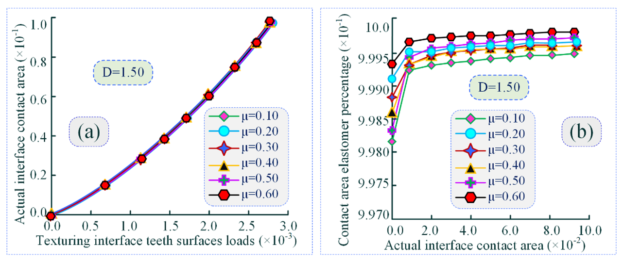
Figure 12Effect of time-varying interfacial friction coefficients on contact area load-bearing characteristic curves law. (a) Effect of actual interface contact area on load characteristics variation of textured surface. (b) Time-varying trend of elastomer share of contact area in meshing domains.
Based on the numerical simulation of the tooth surface meshing model, the TEHL performance of the textured interface under sliding contact in warship PRTS gears is analysed for different micro-texture-scale parameters. The characteristics of the medium layer film, friction coefficient and medium film pressure at the meshing interface are examined in relation to the geometric parameters of the texture morphology, such as pit radius, depth, peak height of micro-convex bodies and width-to-diameter ratio of concave–convex microelements. The time-varying trends of these parameters are analysed to determine the mechanism by which micro-texture-scale parameters influence the lubrication properties and load-bearing performance of the MTMI. This analysis aims to guide the micro-texture topology design and functional optimisation of the contact interface in warship PRTS meshing teeth surfaces.
5.1 Simulation analysis of the influence of pit microelement radius on load-bearing performance
Figure 13a illustrates the time-varying relationship of the minimum medium layer film thickness ratio at the interface under different pit microelement radii during the sliding contact transient of textured meshing teeth surfaces. As shown in the figure, the time-varying curve of the minimum medium layer film thickness ratio at the MTMI exhibits a gradually decreasing trend. The rate of change slows down at the initial stage of TEHL meshing and then accelerates until the end of the meshing process. Comparing the time-varying curves of the minimum medium layer film thickness ratio under different pit microelement radii, it is evident that when the depth of the pit microelements and the height of the convex peak microelements are held constant, an increase in the pit microelement radius (PMER) leads to a gradual increase in the minimum medium layer film thickness ratio at the MTMI. This is particularly evident under TEHL conditions, where an increase in the PMER promotes the accumulation of hydrodynamic fluid within the textured microelements, resulting in an increase in the medium layer film thickness. However, the rate of increase diminishes significantly as the PMER further increases.
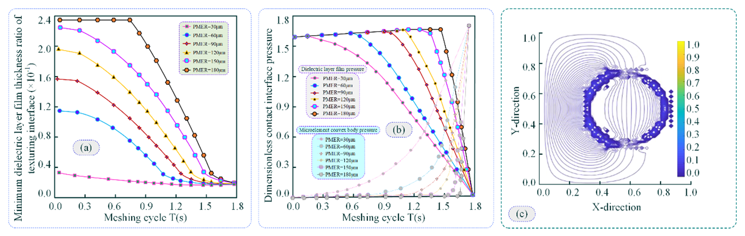
Figure 13Bearing characteristics of the pit microelement radius. (a) Time-varying trend of the interface minimum dielectric layer film thickness ratio for different pit microelement radii. (b) Time-varying trend of the dielectric layer film pressure and pressure of microelement peaks for different pit microelement radii. (c) Cloud view of the interfacial dielectric layer film pressure for different pit microelement radii.
Figure 13b depicts the time-varying relationships of the hydrodynamic medium layer film pressure and the MCP pressure within the meshing time domain. The results indicate that the hydrodynamic medium layer film pressure initially increases gradually and then decreases sharply during the meshing process. In contrast, the MCP pressure increases rapidly within the steady-state meshing region. This behaviour is attributed to the gradual reduction of the meshing gap as the steady-state meshing transient progresses, with the medium layer film pressure playing a dominant role. As the medium layer film pressure increases, the MCP pressure initially emerges and then rises sharply, while the medium layer film pressure gradually diminishes. Comparing the two pressures, it is observed that as the PMER increases, the initial emergence of both the medium layer film pressure and the MCP pressure is progressively delayed. This can be explained by the fact that larger pit microelements store more lubricant, which provides sufficient medium layer film pressure to meet the normal load requirements of the TEHL interface during the meshing transient. Further increasing the PMER does not significantly improve the lubrication and friction performance but may instead inhibit the torque transmission capacity of the meshing pair. Specifically, when the PMER exceeds a certain threshold, the stored lubricant within the pit microelements increases the medium layer film pressure, leading to a gradual reduction in the peak pressure of the micro-convex elements.
In Fig. 13c, an appropriate PMER can increase the hydrodynamic medium layer film thickness to some extent and improve lubrication and friction performance. However, an excessively large PMER results in the stored lubricant within the texture still bearing a portion of the normal load at the end of the meshing transient, thereby reducing the frictional torque at the interface and affecting the torque transmission capacity.
In summary, the results indicate that an appropriate pit microelement configuration can effectively reduce the interface friction coefficient under TEHL conditions during the meshing transient, thereby minimising sliding friction and contact losses. Based on the scale factor of the PMER, if the PMER is too small, the moment at which the medium layer film pressure decreases occurs earlier, weakening the normal load-bearing capacity provided by the medium layer film and exacerbating interface friction and wear. Conversely, if the PMER is too large, it increases the shear friction coefficient of the medium layer film during the initial meshing stage, leading to higher frictional energy losses. Additionally, at the end of the meshing transient, the medium layer film provides a certain load-bearing capacity, which reduces the peak contact pressure of the MCP and negatively impacts torque transmission.
5.2 Simulation analysis of the influence of pit microelement depth on load-bearing performance
Assuming the PMER and the height of the MCP texture are constant, the time-varying relationships of the minimum medium layer film thickness ratio, medium layer film pressure, and MCP texture pressure during the alternating contact transient of meshing teeth surfaces under different pit microelement depths are illustrated in Fig. 14.
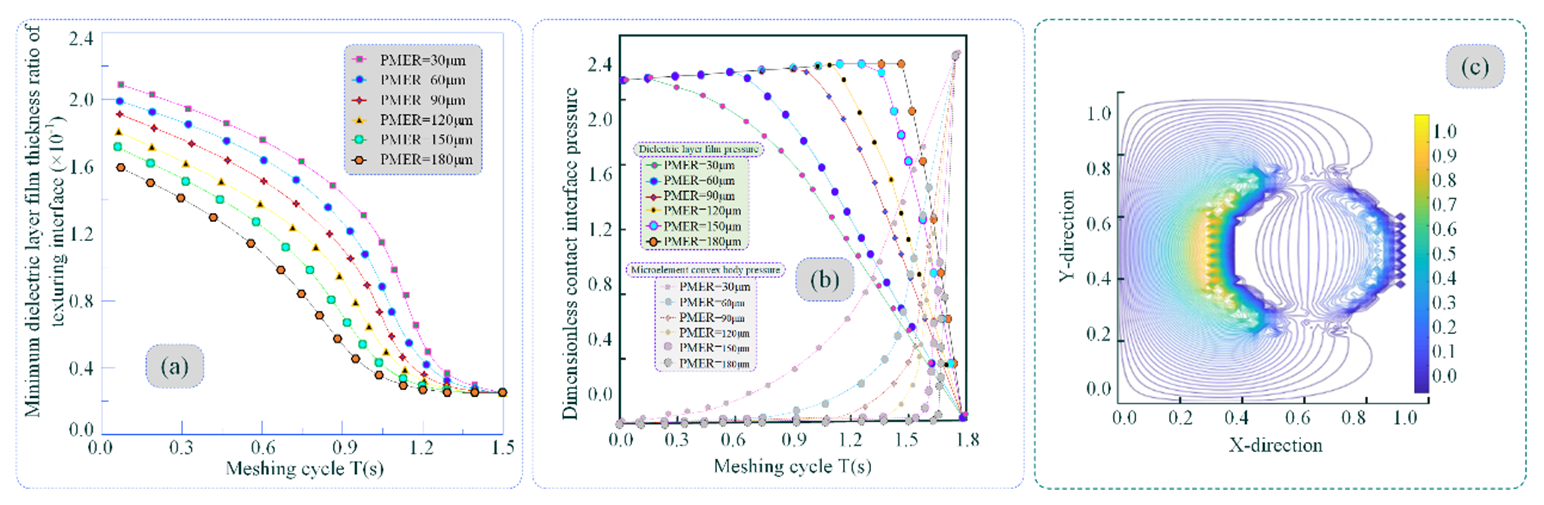
Figure 14Bearing characteristics of the pit microelement depth. (a) Time-varying trend of the interface minimum dielectric layer film thickness ratio for different pit microelement depths. (b) Time-varying trend of the dielectric layer film pressure and pressure of microelement peaks for different pit microelement depths. (c) Cloud view of the interfacial dielectric layer film pressure for different pit microelement depths.
As shown in Fig. 14a, when the pit microelement depth increases, the minimum medium layer film thickness ratio at the interface exhibits a gradually decreasing trend, which is opposite to the effect of the PMER. An increase in the PMER prolongs the contact transient during which the micro-convex peak texture bears pressure. This trend is similar to the influence of the PMER on the medium layer film thickness ratio. Specifically, a larger PMER allows for the accumulation of more hydrodynamic fluid, enhancing the load-bearing capacity of the medium layer film. Consequently, this delays the time domain during which the MCP texture bears the load.
As shown in Fig. 14b and c, when the meshing tooth surface operates under TEHL conditions and the PMER is relatively small, the medium layer film pressure is not significantly affected by changes in the pit microelement depth. This can be attributed to the fact that, under TEHL conditions, the medium layer film thickness at the meshing interface provides sufficient load-bearing capacity, thereby mitigating the influence of the PMER on the minimum medium layer film pressure. Consequently, the effect of the pit microelement depth becomes more pronounced. Additionally, as the PMER increases, the influence of the pit microelement depth on the pressure of the MCP texture gradually diminishes.
5.3 Simulation analysis of the influence of micro-convex peak texture height on load-bearing performance
Assuming the PMER and depth are constant, the time-varying relationships among the minimum medium layer film thickness ratio, medium layer film pressure, and micro-convex peak (MCP) texture pressure during the alternating contact transient of meshing tooth surfaces under different MCP texture heights are illustrated in Fig. 15. As shown in Fig. 15a, as the height of the MCP texture increases, the minimum medium layer film thickness ratio at the interface exhibits a gradually decreasing trend. This is attributed to the fact that the MCP texture increases the surface roughness of the tooth, leading to a reduction in the minimum medium layer film thickness ratio. Excessively high MCP textures can cause the tooth surface to prematurely enter TEHL contact at higher sliding speeds during the meshing transient, thereby exacerbating friction and wear. When the PMER is very small, excessively high MCP textures can also result in an excessively low minimum medium layer film thickness ratio at the interface during the meshing transient, making it difficult to meet the required medium layer film load-bearing capacity under TEHL conditions.
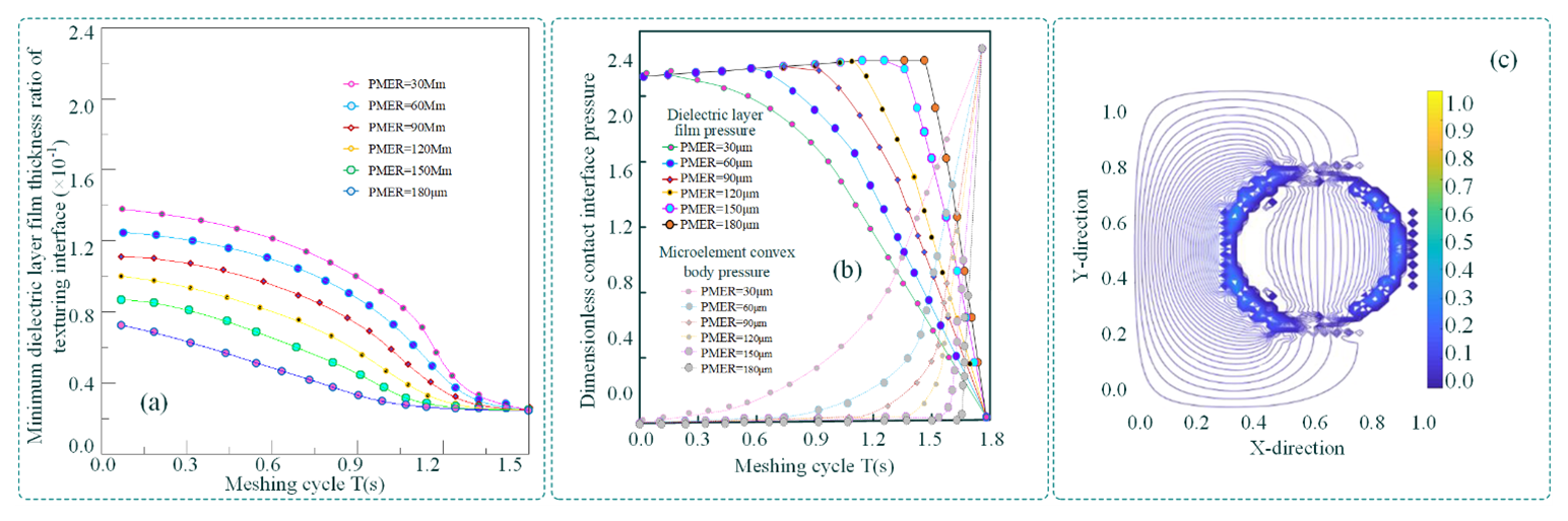
Figure 15Bearing characteristics of pits with microelement convex peak height. (a) Time-varying relationship of interface minimum dielectric layer film thickness ratio. (b) Time-varying trend of dielectric layer film pressure and pressure of microelement peaks. (c) Cloud view of interfacial dielectric layer film pressure.
As shown in Fig. 15b and c, when the height of the MCP texture increases, the pressure of the MCP emerges prematurely, thereby activating the anchoring effect of the MCP to enhance frictional contact and increase the friction coefficient at the MTMI. This is intended to achieve greater torque transmission capacity. When the PMER increases, the pressure of the MCP is delayed, indicating that optimising the matching values of the MCP texture height and radius through coordinated control can improve the torque transmission capacity of the meshing pair. Additionally, appropriately increasing the height of the MCP texture can mitigate the influence of the PMER scale on the peak pressure of the micro-convex texture. As the height of the MCP texture continues to increase, the rate of decline in the maximum peak pressure difference gradually stabilises.
Future research could employ microbial machining to fabricate linear textured surfaces on meshing interfaces, thereby validating the performance of microelement IEL and ASLBC in slip-line contact textured gear pairs. This would provide experimental verification for the theoretical model (Ruan et al., 2022; Wang et al., 2023, 2025).
This study is the first to introduce microelement texture (MET) into the homogeneous interface enriched lubrication (IEL) regulation of the micro-textured meshing interface (MTMI) of warship power rear transmission systems (PRTSs) to control meshing anti-scuffing load-bearing capacity (ASLBC). The proposed novel lubrication and load-bearing evaluation method is original and is expected to break through the limitations of heavy-load gear fatigue and scuffing failure in the warship PRTS, making it immune to the exacerbation of friction and wear caused by changes in lubrication characteristics at the meshing interface. Guided by the actual needs and problems of the warship PRTS gears, this research proposes a new method for evaluating ASLBC with interface micro-texture (IMT) based on the regulation of homogeneous IEL characteristics on the meshing tooth surface. This method has the potential to form a systematic and independent intellectual property system, providing a theoretical foundation and analytical tools for the study of structural design, processing methods, transmission efficiency, lubrication characteristics, fatigue life and reliability of existing warship PRTS gears.
This topic investigates the load-bearing characteristics of textured interfaces under TEHL conditions. A generalised contact load-bearing model for MTMI under TEHL is proposed, incorporating an equivalent contact scale factor. This factor represents the contact area of all micro-convex peaks (MCPs) on the meshing tooth surface using the peak with the highest micro-convex body and modifies the morphological distribution density function to ensure integrability for micro-convex bodies. A distribution density function for the MET in the contact area of the meshing interface is established, enabling more accurate analysis of the actual contact area of the MTMI. A mathematical model for the load-bearing performance of textured meshing interfaces under steady-state TEHL conditions is derived, revealing the relationship between load and the contact stiffness of textured teeth surfaces as well as the damping of the meshing interface. This provides a theoretical foundation and data reference for optimising the IEL effect of MTMI and enhancing the ASLBC of the contact IMT. Based on the research findings, the following conclusions are drawn:
-
The meshing interface load and sliding velocity govern the tooth surface contact stiffness and interface contact damping with similar time-varying patterns. The distribution characteristics of the hydrodynamic fluid medium layer and its film thickness dominate the values of tooth surface contact stiffness and interface contact damping. Meanwhile, the distribution of hydrodynamic fluid film pressure and the layer thickness have a more pronounced influence on the sliding velocity within the meshing region.
-
An increase in the fractal dimension leads to a sharp rise in the number of plastic deformations caused by the peaks of the MET. As the fractal dimension increases, the proportion of elastic elements in the contact area shows a declining trend.
-
Under TEHL conditions with a small pit microelement radius (PMER), the medium layer film pressure is minimally affected by changes in the pit microelement depth. The medium layer film thickness at the MTMI provides sufficient load-bearing capacity, thereby reducing the influence of the PMER on the minimum medium layer film pressure. Consequently, the effect of the pit microelement depth becomes more pronounced. Additionally, as the PMER increases, the influence of the pit microelement depth on the pressure of the micro-convex peak texture gradually diminishes.
This study has the following limitations:
-
The experimental validation remains incomplete, lacking supporting data from actual working conditions of the warship power rear transmission system (PRTS).
-
The research methodology primarily relies on theoretical derivation, and empirical studies need further reinforcement.
For these issues, this study proposes a generalised thermoelastic hydrodynamic lubrication (TEHL) contact load-bearing model with interface micro-texture (IMT). The model employs an equivalent scale factor parameter to characterise the global micro-asperity contact area of the micro-textured meshing interface (MTMI) and ensures the accuracy of micro-asperity calculations by modifying the shape distribution density function. Building upon this foundation, a mathematical model for the anti-scuffing load-bearing capacity (ASLBC) of meshing interfaces under steady-state TEHL conditions is derived. This systematically elucidates the coupling mechanism between contact stiffness and damping of meshing MTMI under alternating loads.
The research findings will help address the limitations of previous studies on the time-varying friction TEHL characteristics of warship PRTSs, which did not fully consider the micro-topography of the rolling/sliding transition points/lines in the contact interface. The study explores how to regulate the multi-scale characterisation parameters of interface micro-texture (IMT) to achieve optimal interface lubrication characteristics and load-bearing performance. This breakthrough overcomes the poor effectiveness of traditional lubrication under harsh operating conditions. Gear surfaces with MTMI maintain a low-friction state at the contact interface for an extended period. This provides the possibility for enriched lubrication and anti-scuffing load-bearing capacity of meshing gear surfaces under high-speed and heavy-load extreme operating conditions in warship PRTSs. Investigating the evolution mechanism of IEL characteristics under the influence of multi-scale characterisation parameters, and coupling the stress field, film thickness field and temperature field with macroscopic parameters such as configuration and load distribution, as well as microscale parameters such as micro-asperity peaks and texture direction, will provide theoretical and technical support for further improving the ASLBC of meshing gear surfaces in warship PRTSs. This is a research work of practical significance.
The code and data included in this article can be made available by the corresponding author upon reasonable request. Please note that the data and codes are confidential and cannot be made publicly available with respect to future applications.
Conceptualisation, XGW and YMW; methodology, WQZ; software, JFR; validation, XGW, YMW and JFR; formal analysis, WQZ; investigation, JFR; resources, YMW; data curation, WQZ; writing–original draft preparation, WQZ and XGW; writing–review and editing, XGW, YMW and JFR; visualisation, JFR; supervision, JFR and WQZ; project administration, YMW and WQZ. All authors have read and agreed to the published version of the paper.
The contact author has declared that none of the authors has any competing interests.
Publisher’s note: Copernicus Publications remains neutral with regard to jurisdictional claims made in the text, published maps, institutional affiliations, or any other geographical representation in this paper. While Copernicus Publications makes every effort to include appropriate place names, the final responsibility lies with the authors.
The authors would like to thank Huaqiao University (HQU) and the Heilongjiang Institute of Technology (HLJIT) for their support. The authors sincerely appreciate all participants for their contributions.
This research was funded by the National Key Research and Development Program Project (grant no. 2023YFB3406301), the National Natural Science Foundation Sponsored Project (Project Approval Number: 52475257), the Fund Project for Technological Field of National Defense Science and Technology Plan 173 (2024-JCJQ-JJ-2020) and (2024-JCJQ-JJ-2043), and the Marine Propulsion Research and Development (MPRD) Program (grant no. MG20220203).
This paper was edited by Jia Ge and reviewed by three anonymous referees.
Ammosov, L., Mönkkönen, K., and Suvanto, M.: Precise fabrication of microtextured stainless steel surfaces using metal injection moulding, Precision Engineering, 62, 89–94, https://doi.org/10.1016/j.precisioneng.2019.11.012, 2020.
Cao, P., Li, Q., Feng, K., and Qin, Y.: Dynamic modeling of spur gear transmission system with evolutive coupling fault of fatigue crack and wear, Engineering Failure Analysis, 156, 107820, https://doi.org/10.1016/j.engfailanal.2023.107820, 2024.
Černe, B., Petkovšek, M., Duhovnik, J., and Tavčar, J.: Thermo-mechanical modeling of polymer spur gears with experimental validation using high-speed infrared thermography, Mechanism and Machine Theory, 146, 103734, https://doi.org/10.1016/j.mechmachtheory.2019.103734, 2024.
Chang, X., Renqing, D., Liao, L., Zhu, P., Lin, B., Huang, Y., and Luo, S.: Study on hydrodynamic lubrication and friction reduction performance of spur gear with groove texture, Tribology International, 177, 107978, https://doi.org/10.1016/j.triboint.2022.107978, 2023.
Chen, W., Lei, Y., Fu, Y., and Hou, L.: A study of effects of tooth surface wear on time-varying mesh stiffness of external spur gear considering wear evolution process, Mechanism and Machine Theory, 155, 104055, https://doi.org/10.1016/j.mechmachtheory.2020.104055, 2021.
Chen, Z., Jiang, Y., Li, S., Tong, Z., Tong, S., and Tang, N.: Uncertainty propagation of correlated lubricant properties in gear tribodynamic system, Tribology International, 179, 107812, https://doi.org/10.1016/j.triboint.2022.107812, 2023.
Cheng, G., Ma, J., Li, J., Sun, K., Wang, K., and Wang, Y.: Study on the Dynamic Characteristics of Gears Considering Surface Topography in a Mixed Lubrication State, Lubricants, 12, https://doi.org/10.3390/lubricants12010007, 2024.
Codrignani, A., Savio, D., Pastewka, L., Frohnapfel, B., and Ostayen, R. V.: Optimization of surface textures in hydrodynamic lubrication through the adjoint method, Tribology International, 148, 106352, https://doi.org/10.1016/j.triboint.2020.106352, 2020.
Croccolo, D., De Agostinis, M., Olmi, G., and Vincenzi, N.: A Practical Approach to Gear Design and Lubrication: A Review, Lubricants, 8, 84, https://doi.org/10.3390/lubricants8090084, 2020.
Galda, L., Sep, J., Olszewski, A., and Zochowski, T.: Experimental investigation into surface texture effect on journal bearings performance, Tribology International, 136, 372–384, https://doi.org/10.1016/j.triboint.2019.03.073, 2019.
Guilbault, R. and Lalonde, S.: A stochastic prediction of roughness evolution in dynamic contact modelling applied to gear mild wear and contact fatigue, Tribology International, 140, 105854, https://doi.org/10.1016/j.triboint.2019.105854, 2019.
Gupta, N., Tandon, N., Pandey, P. K., Vidyasagar, K. E. Ch., and Kalyanasundaram, D.: Tribodynamic studies of textured gearsets lubricated with fresh and MoS2 blended greases, Tribology International, 165, 107247, https://doi.org/10.1016/j.triboint.2021.107247, 2022.
Kaneta, M., Matsuda, K., and Nishikawa, H.: The Causes of Asymmetric Deformation of Surface Roughness Asperities in Elastohydrodynamic Lubrication Contacts, Journal of Tribology, 144, 061601, https://doi.org/10.1115/1.4052255, 2022.
Li, Z., Xiao, H., Tang, Y., Liang, G., Wang, L., and Yang, J.: A deterministic model of surface profile degradation for evaluating time-varying mesh stiffness and dynamic responses of spur gear considering tooth surface wear evolution, Mechanical Systems and Signal Processing, 225, 112313, https://doi.org/10.1016/j.ymssp.2025.112313, 2025.
Liu, H. L., Liu, H. J., Zhu, C. C., and Parker, R. G.: Effects of lubrication on gear performance: A review, Mechanism and Machine Theory, 145, 103701, https://doi.org/10.1016/j.mechmachtheory.2019.103701, 2020.
Liu, W. L., Ni, H. J., Wang, P., and Chen, H. L.: Investigation on the tribological performance of micro-dimples textured surface combined with longitudinal or transverse vibration under hydrodynamic lubrication, International Journal of Mechanical Sciences, 174, 105474, https://doi.org/10.1016/j.ijmecsci.2020.105474, 2020.
Meng, F. M., Yu, H. Y., Gui, C., and Chen, L. Experimental study of compound texture effect on acoustic performance for lubricated textured surfaces, Tribology International, 133, 47–54, https://doi.org/10.1016/j.triboint.2018.12.036, 2019.
Marques, P. M. T., Marafona, J. D. M., Martins, R. C., and Seabra, J. H. O.: A continuous analytical solution for the load sharing and friction torque of involute spur and helical gears considering a non-uniform line stiffness and line load, Mechanism and Machine Theory, 161, 104320, https://doi.org/10.1016/j.mechmachtheory.2021.104320, 2021.
Özdemir, M. N., Kılıç, V., and Ünlüsoy, Y. S.: A new contact & slip model for tracked vehicle transient dynamics on hard ground, Journal of Terramechanics, 73, 3–23, https://doi.org/10.1016/j.jterra.2017.07.001, 2017.
Petare, A. C., Mishra, A., Palani, A., and Jain, N. K.: Study of laser texturing assisted abrasive flow finishing for enhancing surface quality and microgeometry of spur gears, The International Journal of Advanced Manufacturing Technology, 101, 785–799, https://doi.org/10.1007/s00170-018-2944-3, 2019.
Rajput, H., Atulkar, A., and Porwal, R.: Optimization of the surface texture on piston ring in four-stroke IC engine, Materials Today: Proceedings, 44, Part 1, 428–433, https://doi.org/10.1016/j.matpr.2020.09.752, 2021.
Rosenkranz, A., Grützmacher, P. G., Gachot, C., and Costa, H. L.: Surface texturing in machine elements-A critical discussion for rolling and sliding contacts, Advanced Engineering Materials, 21, 1900194, https://doi.org/10.1002/adem.201900194, 2019.
Ruan, J., Wang, X., Wang, Y., and Li C.: Study on Anti-Scuffing Load-Bearing Thermoelastic Lubricating Properties of Meshing Gears With Contact Interface Micro-Texture Morphology, Journal of Tribology, 144, 101202, https://doi.org/10.1115/1.4054400, 2022.
Sánchez, M. B., Pleguezuelos, M., and Pedrero, J.: Strength model for bending and pitting calculations of internal spur gears, Mechanism and Machine Theory, 133, 691–705, https://doi.org/10.1016/j.mechmachtheory.2018.12.016, 2019.
Sivayogan, G., Dolatabadi, N., Johns-Rahnejat, P., Rahmani, R., and Rahnejat, H.: Non-Newtonian Thermo-Elastohydrodynamics and Sub-Surface Stress Field of High-Performance Racing Spur Gears, Lubricants, 10, 146, https://doi.org/10.3390/lubricants10070146, 2022.
Tu, Zh. R., Meng, X. K., Ma, Y., and Peng, X. D.: Shape optimization of hydrodynamic textured surfaces for enhancing load-carrying capacity based on level set method, Tribology International, 162, 107136, https://doi.org/10.1016/j.triboint.2021.107136, 2021.
Wang, X., Huang, H., Song, J., Wang, Y., and Ruan, J.: Numerical Analysis of Friction Reduction and ATSLB Capacity of Lubricated MTS with Textured Micro-Elements, Lubricants, 11, 78, https://doi.org/10.3390/lubricants11020078, 2023.
Wang, X., Ruan, J., Wang, Y., and Zou, W.: Analytical and Experimental Research of Lubrication Load-Bearing Characteristics of Microtextured Meshing Interface, Materials, 18, 845, https://doi.org/10.3390/ma18040845, 2025.
Wang, X. G., An, S. Y., Wang, Y. M., Ruan, J. F., and Ji, S. E.: TEM fitting considering TEPs of contact interface of meshing gear, Journal of Mechanical Science and Technology, 35, 10, 4443–4457, https://doi.org/10.1007/s12206-021-0915-3, 2021.
Wang, X. G., Huang, H., Song, J. Y., Wang, Y. M., and Ruan, J. F.: Numerical Analysis of Friction Reduction and ATSLB Capacity of Lubricated MTMI with Textured Micro-Elements, Lubricants, 11, https://doi.org/10.3390/lubricants11020078, 2023.
Wang, Y., Azam, A., Zhang, G., Dorgham, A., Liu, Y., Wilson, M. C. T., and Neville A.: Understanding the Mechanism of Load-Carrying Capacity between Parallel Rough Surfaces through a Deterministic Mixed Lubrication Model, Lubricants, 10, https://doi.org/10.3390/lubricants10010012, 2022.
Wos, S., Koszela, W., and Pawlus, P.: Comparing tribological effects of various chevron-based surface textures under lubricated unidirectional sliding, Tribology International, 146, 106205, https://doi.org/10.1016/j.triboint.2020.106205, 2020.
Xing, Y. Q., Li, X., Hu, R. Y., Long, X. Y., Wu, Z., and Liu, L.: Numerical analyses of rectangular micro-textures in hydrodynamic lubrication regime for sliding contacts, Meccanica, 56, 365–382, https://doi.org/10.1007/s11012-020-01296-x, 2021.
Yang, Y., Tang, J., Hu, N., Shen, G., Li, Y., and Zhang, L.: Research on the time-varying mesh stiffness method and dynamic analysis of cracked spur gear system considering the crack position, Journal of Sound and Vibration, 548, 117505, https://doi.org/10.1016/j.jsv.2022.117505, 2023.
Zhang, N., Zhai, W., Yin, S., Chen, S., Xia, J., Luan, L., and Zhai, A.: Deep-sea soft soil and deep-sea mining vehicle interaction: From soil properties to locomotion performance, Applied Ocean Research, 154, 104372, https://doi.org/10.1016/j.apor.2024.104372, 2025.
Zhao, J., Hou, L., Li, Z., Zhang, H., and Zhu, R.: Prediction of tribological and dynamical behaviors of spur gear pair considering tooth root crack, Engineering Failure Analysis, 135, 106145, https://doi.org/10.1016/j.engfailanal.2022.106145, 2022a.
Zhao, J., Sheng, W., Li, Z., Zhang, H., and Zhu, R.: Effect of lubricant selection on the wear characteristics of spur gear under oil-air mixed lubrication, Tribology International, 167, 107382, https://doi.org/10.1016/j.triboint.2021.107382, 2022b.
- Abstract
- Introduction
- Steady-state TEHL textured interface load-bearing contact modelling
- Analysis of lubrication load-bearing characteristics considering the textured interface contact model
- Simulation analysis of the influence of texture parameters on the load-bearing performance of the MTMI
- Simulation analysis of the influence of micro-texture-scale parameters on meshing load-bearing performance
- Discussion of the results
- Conclusions
- Code and data availability
- Author contributions
- Competing interests
- Disclaimer
- Acknowledgements
- Financial support
- Review statement
- References