the Creative Commons Attribution 4.0 License.
the Creative Commons Attribution 4.0 License.
 | 29 Sep 2025
Energy self-consistency of small aircraft combining triboelectric nanogenerator structure and flexible-wing technology
Zhiqiang Liu
Stable energy output is crucial for the sustained flight of small aircraft, particularly flapping-wing air vehicles (FAVs). Traditional energy supply methods, such as batteries, suffer from limitations in weight, range, and environmental impact. This study proposes a novel energy self-consistent model (ESCM) for FAVs that integrates a triboelectric nanogenerator (TENG) structure into a flexible-wing technology (FWT) based on silk protein. The TENG is designed to harvest energy from the wing's deformation during flapping motion. The experimental results demonstrated that the proposed model maintained an average energy output of 29.6 ± 3.4 mW over a 100 h simulated flight test, with a stability index of 3.5. Compared with the control group using traditional flexible wings without an integrated TENG, the performance of the research model improved by 36.82 %, with an average energy output of 29.6 ± 3.4 mW and a stability index of 1.8. With the increase in the number of cycles, the energy recovery accuracy of the wing has been improved, reaching up to 93.5 %. This innovative approach provides a promising solution for the energy challenges of small aircraft, paving the way for more sustainable and efficient flight.
- Article
(8336 KB) - Full-text XML
- BibTeX
- EndNote


Flapping-wing aerial vehicles (FAVs), inspired by the flight mechanisms of birds and insects, have garnered significant attention due to their superior maneuverability, energy efficiency, and stealth capabilities, making them well suited for diverse applications (Zhang et al., 2021). However, the technological advancement of FAVs remains constrained by critical challenges, particularly in energy supply (Xu et al., 2022). Most existing FAVs rely on batteries, which inherently limit flight endurance due to their relatively low power density (Xiao et al., 2021). To overcome this limitation, researchers have explored alternative power sources such as micro fuel cells and solar energy. However, these approaches also suffer from drawbacks, including inefficiencies, additional weight burdens, and operational constraints (Yousaf et al., 2021; Ozaki et al., 2023).
Conventional energy supply methods present several challenges, including excessive system weight, restricted flight duration, and environmental concerns related to battery disposal (Kim et al., 2021). Addressing these limitations requires innovative energy solutions capable of enhancing flight endurance without imposing additional weight penalties. One promising approach involves harvesting energy directly from the flapping motion of the wings. Among various energy-harvesting technologies, triboelectric nanogenerators (TENGs) have attracted significant interest due to their ability to convert mechanical energy into electrical energy, offering a self-sustaining power source for lightweight aerial systems. TENGs are particularly well suited for capturing energy from low-frequency, irregular motions such as flapping wings. Prior studies have demonstrated their effectiveness in various applications. Wang et al. (2021) explored the charge transfer mechanisms in TENGs and their potential for self-powered sensors and energy harvesting. Wang et al. (2023) developed a networked TENG system for blue energy harvesting. Zhang et al. (2022) introduced a super-lubricating TENG to mitigate friction and wear issues. Xu et al. (2023) proposed a direct-current (DC) TENG to enhance current density and simplify circuit management. However, existing research primarily focuses on relatively simple- or predictable-motion environments, leaving the integration of TENGs into the complex, dynamic flapping-wing systems largely unexplored (Li et al., 2022; Xie et al., 2023; Zhao et al., 2022; Wu et al., 2022; Wang et al., 2023; Cui et al., 2022).
To bridge this gap, this study proposes a FAV energy self-consistent model (FAV-ESCM), integrating a TENG structure into a silk protein-based flexible-wing technology (FWT). Flexible wings have shown significant advantages in the aviation field, such as improving lift and delaying stall, providing the possibility for dynamic adaptation of aircraft shapes (Guo et al., 2021; Ahmad et al., 2024). The TENG is seamlessly embedded within the wing structure, harnessing the cyclic deformation and contact–separation interactions of the flapping motion to generate electrical power. This harvested energy serves as a supplementary power source, effectively extending flight endurance and reducing reliance on traditional battery systems. Compared to previous studies that focused on TENGs in other applications or flexible wings alone, this study emphasizes the synergistic integration of these two technologies to optimize the energy harvesting of FAVs in dynamic and complex motion environments. By utilizing this new approach, the study aims to advance energy-efficient FAV design and provide new insights into sustainable power solutions for the next generation of bio-inspired aerial systems.
The main structure of this study is divided into four sections. The first section is an analysis of the current research status to point out the shortcomings of the current research. The second section analyzes the TENG structure and the energy dissipation factors of small aircraft and builds an FAV-ESCM that combines the TENG structure and FWT. The third section is an analysis of the energy recovery effect and the practical application of the proposed model. The last section is a summary of the research results, pointing out the shortcomings of the study and providing prospects for future research.
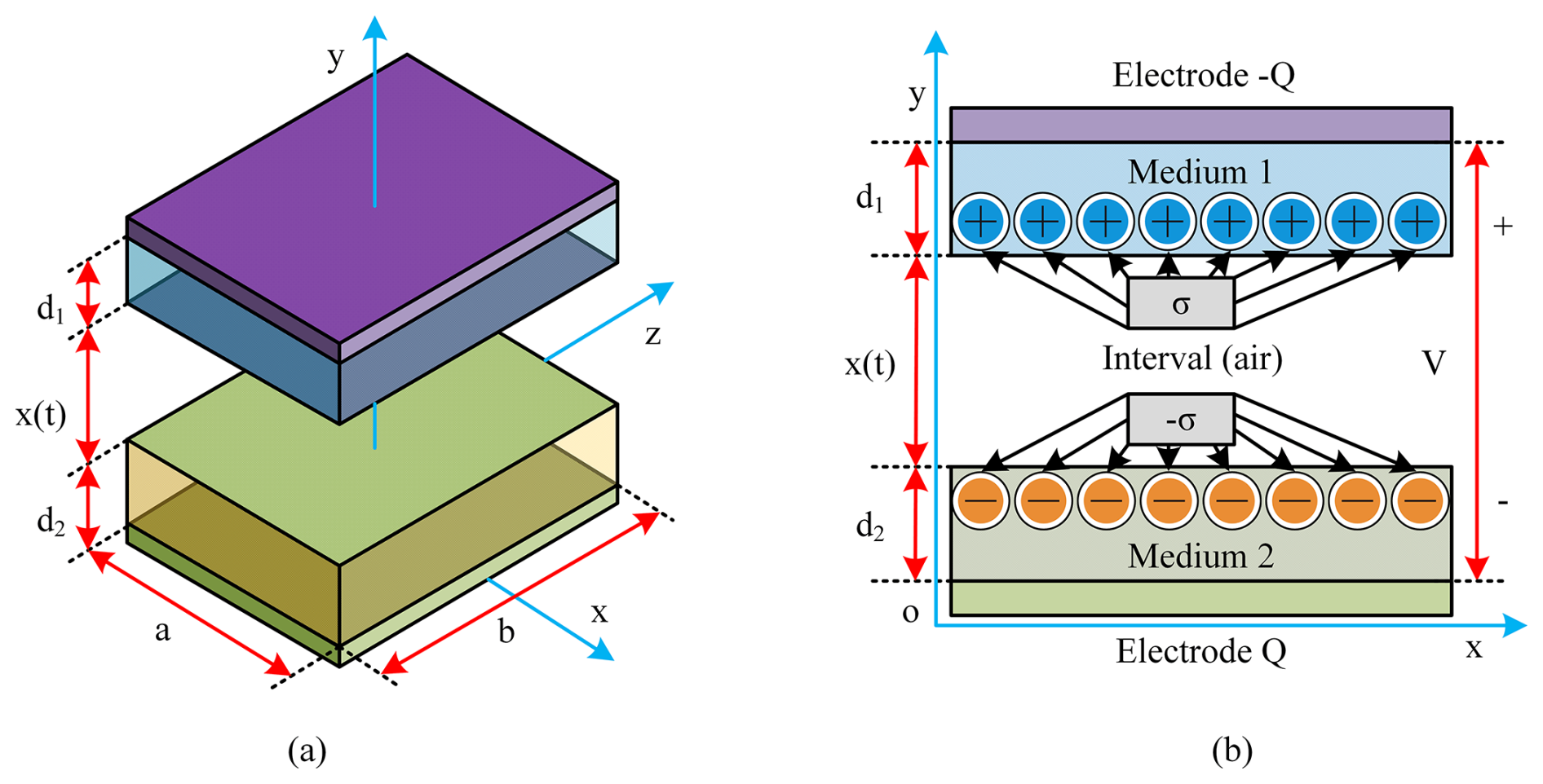
Figure 1Operating principle and framework diagram of TENG structure. (a) The motion principle of TENG structure, (b) TENG simplified structural framework.
2.1 TENG structure and power consumption factors of small aircraft
This study utilizes a TENG structure based on the principle of contact electrification and electrostatic induction to convert mechanical energy from wing flapping into electrical energy. The TENG consists of two layers with different electron affinities: a silk protein layer (positive triboelectric material) and a polytetrafluoroethylene (PTFE) layer (negative triboelectric material). When these layers come into contact and separate due to the flapping motion, electrons transfer from the silk protein to the PTFE, creating a charge separation. This potential difference drives electron flow through an external circuit, generating electricity (Choi et al., 2023). The operating principle diagram of the TENG structure is shown in Fig. 1.
In Fig. 1, the internal electrical strength of TENG structural medium 1 is shown in Eq. (1).
In Eq. (1), Q is the transferred charge; E1 is the electric field strength inside dielectric layer 1; S is the area of the electrode layer, which is the area of the charge distribution region; ε0 is the vacuum dielectric constant; and εr1 is the relative dielectric constant of dielectric layer 1, which is a dimensionless quantity representing the capacitance capacity of dielectric layer 1 relative to a vacuum. The internal power intensity of medium 2 is shown in Eq. (2).
In Eq. (2), E2 denotes the electric field strength in dielectric layer 2. The term εr2 corresponds to the relative permittivity of dielectric layer 2. The Eair (the electrical strength of the frictional gap (air) between medium 1 and medium 2) is shown in Eq. (3).
In Eq. (3), σ is the frictional charge density, and t is time. The calculation of the voltage between the two electrode layers is shown in Eq. (4).
In Eq. (4), V is the voltage between the electrodes; x(t) denotes the length of the air gap between the two dielectric layers, which changes by time; and d1 and d2 are distance parameters between medium 1 and medium 2. In summary, the TENG structure can convert mechanical energy between the media into electrical energy through the contact between the friction layer and the electrode. Therefore, the TENG structure can be applied to meet the aerodynamic power supply needs of small aircraft. Equations (1)–(4) describe the basic working principle of TENG in ideal contact separation mode, describing the process of charge transfer and potential difference generation. These equations assume that the contact between the friction layers is uniform and complete, and the separation distance is also uniformly controllable. However, the flexible wings of flapping-wing aircraft undergo complex non-uniform deformation during periodic flapping, posing challenges for the practical application of the formula. Therefore, in the application context of flapping-wing aircraft, it is necessary to introduce dynamic parameters into the equation to reflect the effects of non-uniform contact and dynamic air gap changes on charge transfer. Accurately predicting the behavior of these parameters during real flapping processes requires the use of multi-physics field simulations that can simulate flexible structural deformation, contact mechanics, and frictional electric coupling or calibration through precise in situ experimental measurements. This study focuses on FAVs, which are characterized by their light weight, small size, low noise, and biomimetic capabilities (Pan et al., 2024; Ozaki et al., 2021). The energy consumption of FAVs comes from both the energy consumed by the aircraft and the aerodynamic energy generated by wing flapping. When FAV flies in the flow field, the ratio of its inertial force to viscous force, i.e., Reynolds number, is a key parameter for determining the effect of viscous force. The calculation is shown in Eq. (5) (Terze et al., 2021; Gayango et al., 2023).
In Eq. (5), Rc is the Reynolds number, ρ is the fluid density in the air, v is the fluid velocity, μ is the coefficient of dynamic viscosity, and l is a certain characteristic size of an object. During FAV flight, it is also necessary to comply with the similarity criterion of unsteady flow, which is the Strouhal number. The mathematical expression is shown in Eq. (6).
In Eq. (6), St is the Strouhal number. The calculation of the FAV rise coefficient is shown in Eq. (7).
In Eq. (7), CL is the FAV rise coefficient, and L is the rise height. The resistance experienced by the aircraft during ascent and flight also generates energy consumption, and the formula for bearing resistance is shown in Eq. (8).
In Eq. (8), CD is the FAV resistance coefficient, and D is the resistance. In addition to resistance, the aircraft also generates induced resistance during ascent. Induced drag is the additional drag induced by the generation of lift, as shown in Eq. (9).
In Eq. (9), CDi is the induction coefficient, and Di is the induced additional resistance. Based on the above calculation formula, FAVs often experience more resistance and generate more energy consumption when flying with upward propulsion. Therefore, this study proposes that FAVs adopt flexible wing forms, such as flexible membranes, which can help reduce the overall weight and resistance of the aircraft and improve flight efficiency and endurance. The transmission energy consumption of flexible FAVs is shown in Fig. 2.
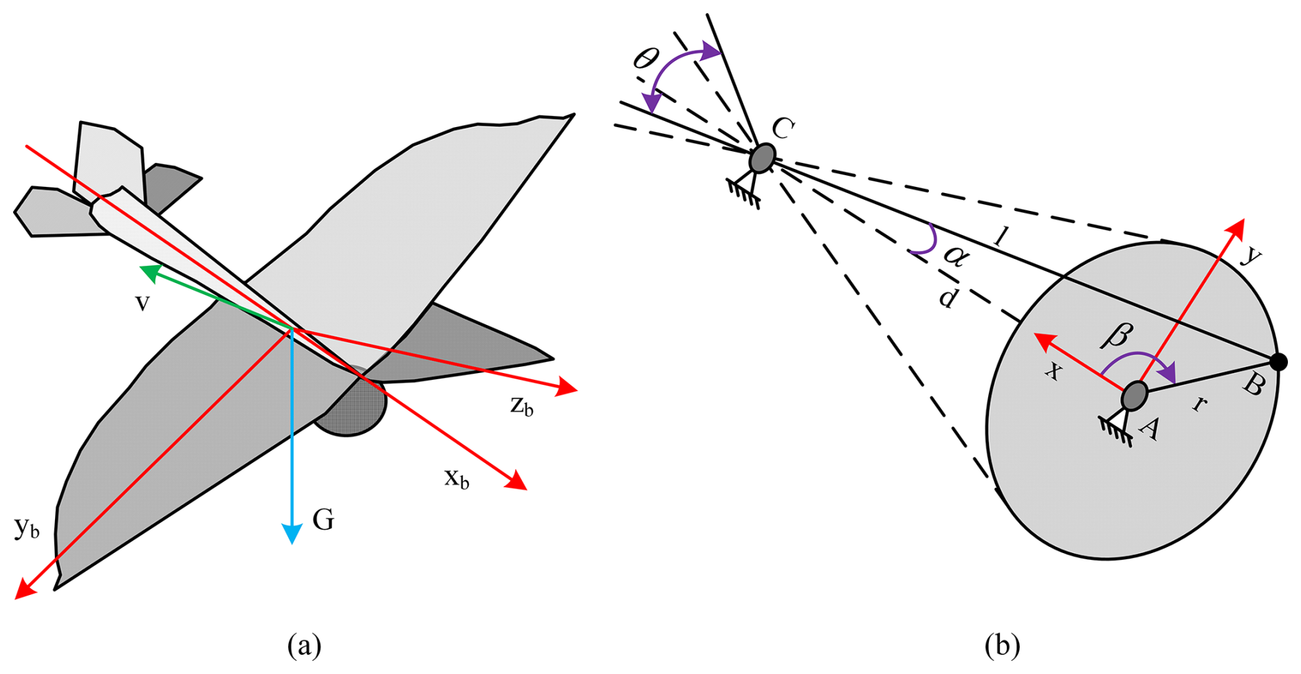
Figure 2Schematic diagram of transmission energy consumption of FAV. (a) Flexible flapping-wing aircraft style, (b) force analysis of flexible flapping-wing aircraft.
In Fig. 2, the flapping angle of the wings of the flexible FAV is composed of the up and down stroke angles. θ⋅r is the swing angle of the wings. The angular velocity is shown in Eq. (10).
In Eq. (10), d is the distance between the center of rotation of the aircraft's crankshaft and the center of the gear disk, β is the transmission angle, wr is the angular velocity of the crankshaft, and r is the length of the crankshaft. The angular velocity is linked to the wing flapping frequency of the aircraft, and the relationship between the two is shown in Eq. (11).
In Eq. (11), f is the flapping frequency of the flexible wing.
2.2 TENG structure integrated into FWT and ESCM
After mastering the self-powering characteristics of TENG structures and the energy consumption factors of flexible FAVs, this study can further control the energy utilization efficiency of aircraft. The efficient TENG structure design can effectively capture the mechanical energy during flapping flight and use it as an auxiliary energy source to enhance the efficiency of flapping flight (Huang, et al., 2022). Membrane structures have become a potential solution for spacecraft systems due to their advantages of light weight, efficient space utilization, and ease of deployment. Focusing on the multifunctionality of flexible materials can achieve dual improvements in energy harvesting and flight performance (Zhao et al., 2023); Shinde and Upadhyay, 2021). Given the strict standards for pursuing miniaturization and lightweighting in flexible-wing surface FAVs, this study proposes using silk protein as the main material for flexible wings. It is a type of fibrous protein extracted from silkworm cocoons, a natural polymer material with unique physical and chemical properties (Chattaraj and Ganguli, 2023). Silk protein materials have positive electricity and strong moisture absorption and are easy to process into various forms, such as fiber, film, gel, etc. The above characteristics suggest that silk protein is suitable for the production requirements of flexible wings (Aliabadi et al., 2023). The flexible wing frame with the integrated TENG structure made of silk protein in this study is shown in Fig. 3.
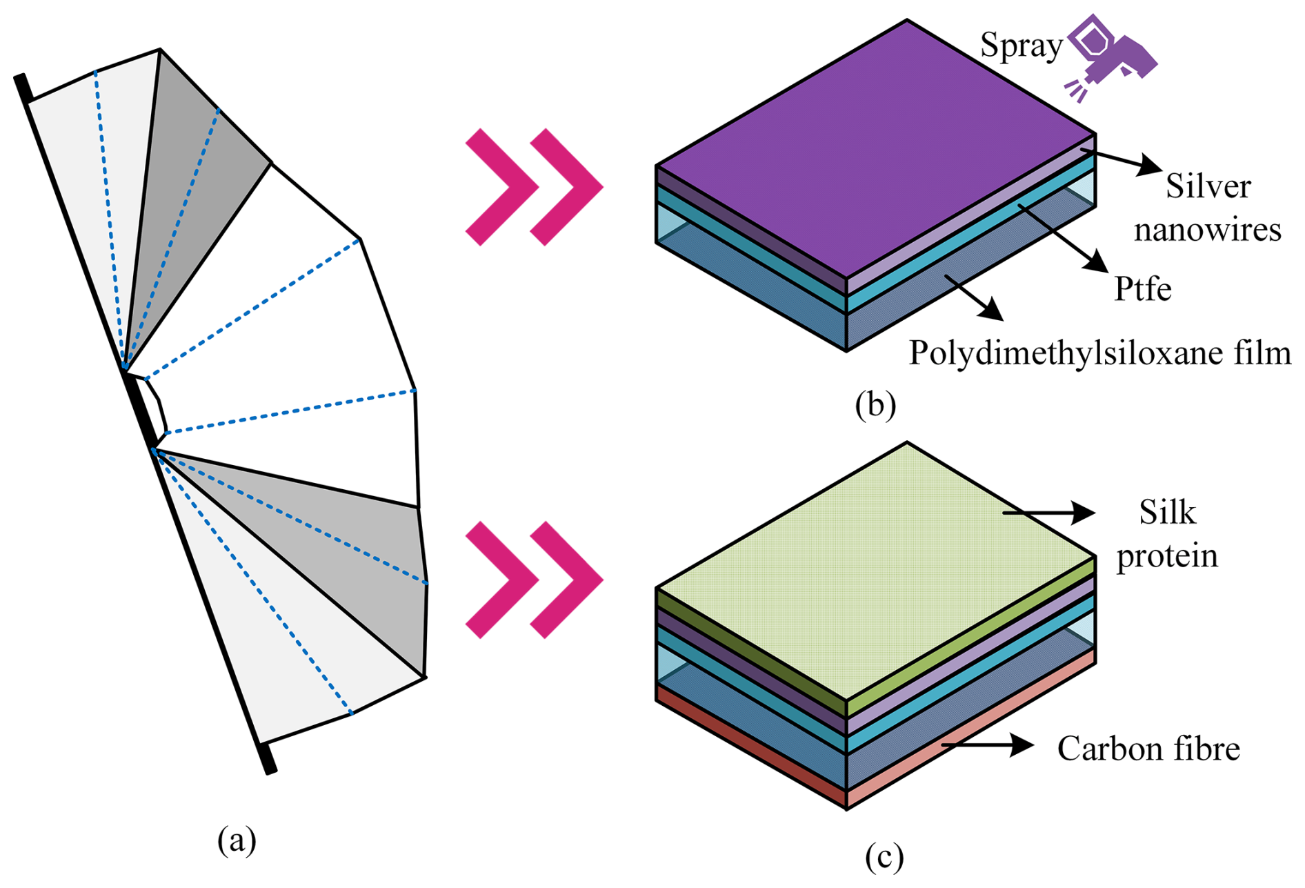
Figure 3Schematic diagram of TENG-integrated flexible wing structure. (a) TENG-structure-integrated flexible wing, (b) electrode layer, (c) frictional layer.
In Fig. 3, this study integrates TENG structures made of silk protein into flexible wings, and the electrode layer is made of polydimethylsiloxane film as the wing base. The electrode layer is uniformly and tightly coated on the surface of PTFE, and finally, Ag nanowires (AgNWs) are welded together to solidify into a compact electrode network. The silver nanowire electrode increases the weight of the wing and requires higher lift from the aircraft, which leads to increased induced drag and requires more power during flapping, resulting in increased power consumption of the drive system. When the flight speed and air density are constant, the induced drag increases, the lift-to-drag ratio decreases, and the flight performance of the aircraft deteriorates. The wing film material is smoothed through a friction layer and then placed with its back facing up in an acrylic box that matches the size. Next, silk protein solution is dropped onto the upper surface of the wing membrane, and it is ensured that the solution is evenly applied to the membrane. When integrating TENG structures, flexible wings face inherent mechanical energy loss issues such as structural vibration, wing surface jitter, friction between wing surfaces, and non-active deformation (Fu et al., 2023). The TENG structure integrates flexible-wing energy self-production and energy conversion functions, as shown in Fig. 4.
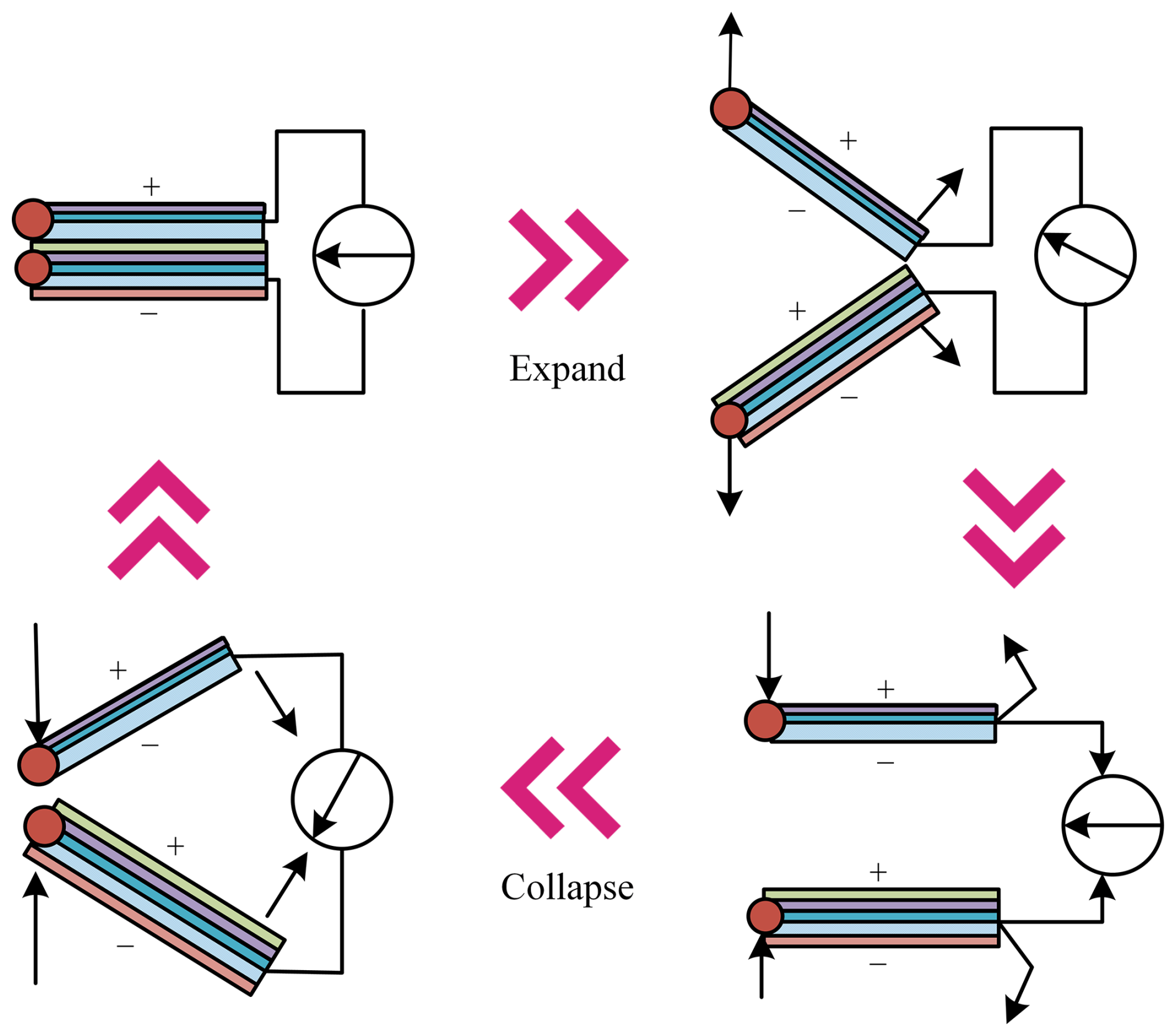
Figure 4TENG-structure-integrated flexible-wing energy self-production and energy conversion function.
In Fig. 4, the flexible wing with the integrated TENG structure will experience brief contact and separation due to flapping during flight. When the upper and lower wings come into contact, the friction between the materials is converted into an electric charge, which is used to supplement the flight energy. When the flexible wings with the integrated TENG structure perform periodic flapping, they can continuously deliver AC energy to external circuit loads, thereby achieving a self-consistent supply of flight energy. The calculation of the spatial electromagnetic field within the range of wing flapping during flight is shown in Eq. (12).
In Eq. (12), A(r,t) is the vector potential of the electromagnetic field at position r and time t, μ is the magnetic permeability, π is pi, r′ is the position of the wing source point, r is the position of the wing observation point, c is the propagation speed of electromagnetic waves in a vacuum, dr′ is the numerical value of the source point position, and J is the current density. The energy conversion process of TENG is described by the function of the interlayer spacing of the medium, as shown in Eq. (13).
In Eq. (13), h1(t) is the linear motion of the wing, and hmax is the maximum clearance distance. The gap function under sinusoidal periodic motion is shown in Eq. (14).
In Eq. (14), h2(t) represents the sinusoidal periodic motion of the wing. The flexible-wing automatic transduction output with the integrated TENG structure is shown in Eq. (15).
In Eq. (15), φ(r,t) is the electrical energy output at position r and time t, and ε is the permittivity of the dielectric. Equations (12) and (15) provide the basic physical framework for describing the electromagnetic field generated by the flapping of flexible wings and the output of TENG electrical energy. However, to quantitatively analyze and predict the energy harvesting performance of the integrated system, this study conducts experiments on the COMSOL multi-physics field simulation software platform based on the finite-element method. The automatic energy transfer output characteristics of TENG-structure-integrated flexible-wing flapping aircraft under different operating conditions have been mastered. On this basis, a FAV-ESCM combining a TENG structure and FWT is built. The operational structure of ESCM is shown in Fig. 5.
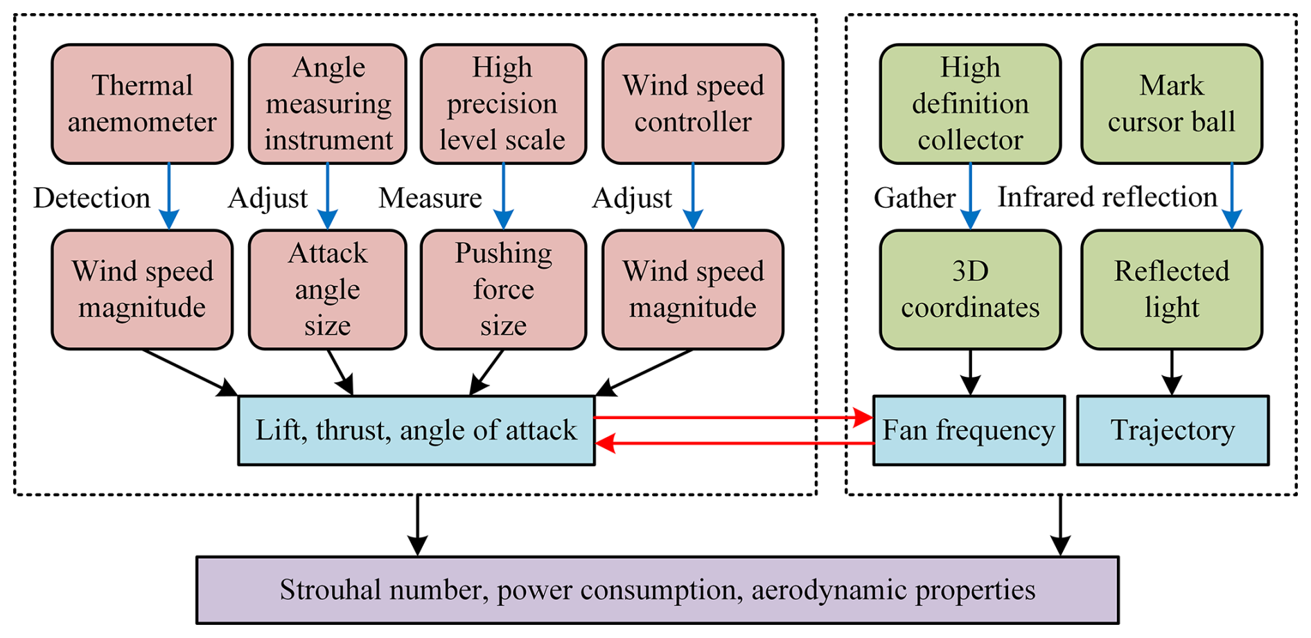
In Fig. 5, to ensure that the flexible wing with the integrated TENG structure maintains stable energy self-supply output and real-time detection output status under any space flight motion, the model also includes modules such as wind speed detection, angle measurement, high-definition acquisition, and infrared tracking. It determines the friction level of the TENG structure by analyzing the wind speed, angle of attack, and lift to analyze the stability of the energy transfer. High-definition acquisition is a small-scale positioning and tracking function that constantly transmits the position of the aircraft and the 3D state of the wings to grasp the flapping frequency of the flexible wings. Infrared tracking is used to determine the trajectory of an aircraft, ensuring that it is in a state of gentle acceleration, reducing significant upward movements, and ensuring the friction frequency of flexible wings. Meanwhile, to achieve genuine energy autonomy, the model also integrates a crucial energy management loop. The core functions of this loop include energy harvesting and rectification, voltage regulation and impedance matching, energy storage, and load power supply management. The AC pulse power generated by TENG is first converted into DC power through a bridge rectifier circuit. Then, the voltage is reduced to a range suitable for charging subsequent energy storage components, and necessary impedance matching is performed to maximize energy transmission efficiency. The regulated power is stored in a high-power-density, fast-charging and fast-discharging supercapacitor. Finally, the stored energy provides DC power with stable voltage to the critical loads of the aircraft through a voltage regulator circuit. This energy management circuit works together with the monitoring module in Fig. 5 to form a closed-loop system of perception, harvesting, storage, and utilization. In theory, the constructed model can achieve the self-consistent aerodynamic energy effect of flexible-wing FAVs.
3.1 Analysis of the energy recovery effect of TENG-structure-integrated flexible wings
To verify the energy supply performance of the proposed TENG structure for FAV, experiments are conducted. This study conducts experimental verification of the FAV-ESCM, which combines a TENG structure and FWT through software simulation. Firstly, a detailed 3D geometric model of a flapping-wing aircraft with TENG-integrated flexible wings is constructed using 3ds Max and Blender software, accurately simulating its physical structure and kinematic characteristics. Then, the geometric model is imported into the COMSOL Multiphysics simulation platform, the physical field is selected, and boundary conditions and excitations are set. During the simulation process, the key parameters are systematically changed, and the open-circuit voltage and short-circuit current waveforms of the TENG output terminal are monitored and recorded in real time. In actual flight, random fluctuations in excitation wind speed may affect the stability of energy output. To address this challenge, this study ensures a stable energy supply through an energy management circuit, ensuring the aircraft's self-sufficiency and high stability in complex environments. The main sources of experimental data include TENG output voltage and current as well as FAV flight time, flight altitude, wing beat frequency, and other indicators. Table 1 shows the equipment and parameters involved in the experiment.
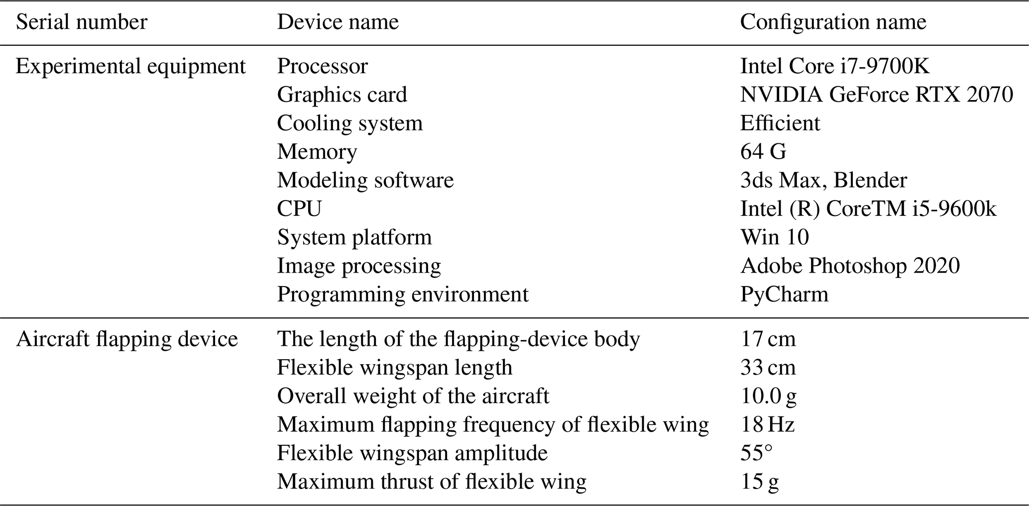
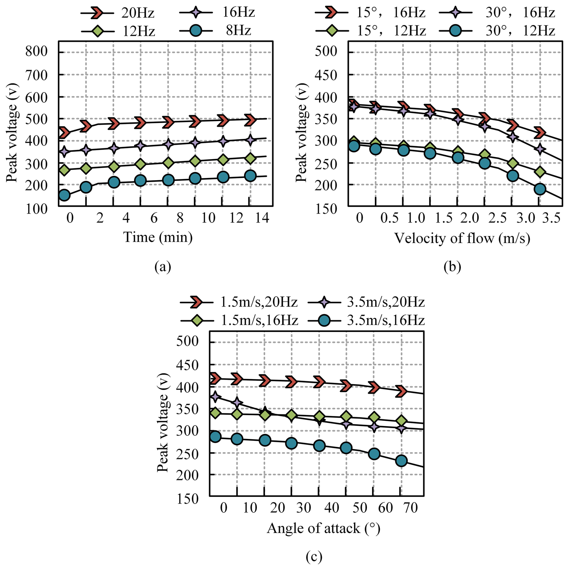
Figure 6Energy output changes generated by wing-flapping frequency of FAV in different states. (a) Energy output at different peak voltages and operating times, (b) energy output affected by flow velocity, (c) energy output affected by angle of attack.
The experiment investigates the effects of flapping frequency, flow velocity, and angle of attack on the energy output of the FAV, as shown in Fig. 6. Figure 6a illustrates the influence of different flapping frequencies on energy output under a flow velocity of 0 m s−1 and an angle of attack of 15°. Over time, the peak voltage at each flapping frequency gradually increases, indicating an overall enhancement in energy output. Notably, at a flapping frequency of 20 Hz, the peak voltage reaches approximately 500 V at 14 min, which is significantly higher than the 235 V recorded at 8 Hz. This finding suggests that higher flapping frequencies can effectively improve energy output, making them more suitable for applications requiring high energy demands. This is because the higher the flapping frequency of the wings, the more contact and separation time the TENG structure has per unit time and the more frequent the charge transfer, resulting in more energy output. At the same frequency, the higher the voltage, the stronger the electric field and the more complete the charge transfer, resulting in an increase in energy output. Figure 6b further examines the impact of different flow velocities (0.5–3.5 m s−1) on energy output at flapping frequencies of 12 and 16 Hz under angles of attack of 15 and 30°. The results indicate that energy output decreases with increasing flow velocity across different conditions. When the flow rate is too high, it may cause unstable flapping of the wings and reduce energy recovery efficiency. Notably, at 16 Hz, the reduction in energy output with increasing flow velocity is less pronounced compared to 12 Hz, suggesting that at higher flapping frequencies, the energy output of the FAV is less sensitive to variations in flow velocity. Additionally, when the flow velocity is 3.5 m s−1, the peak voltage at a flapping frequency of 16 Hz and an angle of attack of 15° reaches approximately 300 V, which is significantly higher than that observed at an angle of attack of 30°. Figure 6c presents the effect of different angles of attack (0–70°) on energy output at flow velocities of 1.5 and 3.5 m s−1 and flapping frequencies of 20 and 16 Hz. In general, energy output exhibits a decreasing trend as the angle of attack increases. This is because when the angle of attack is too high, it may cause wing stall, airflow separation, and reduced energy recovery efficiency. However, at a lower flow velocity (1.5 m s−1), the rate of decrease is relatively smaller. Moreover, when the angle of attack reaches 70°, the peak voltage at a flapping frequency of 20 Hz and a flow velocity of 1.5 m s−1 is the highest, approximately 385 V, which is notably higher than that recorded at a flow velocity of 3.5 m s−1 under the same frequency. Based on the comprehensive analysis of the experimental results in Fig. 6a, b, and c, the combination of a flapping frequency of 20 Hz and a 15° angle of attack has a significant energy output advantage in static or low-speed environments. However, this advantage is not universally applicable to all working conditions. When the environmental flow rate increases, or the angle of attack changes, the optimal parameter combination will change. For example, at higher flow rates, a flapping frequency of 16 Hz exhibits better robustness compared to 20 Hz. Therefore, there is no absolute universal optimal frequency and angle-of-attack value. The maximization of energy output requires dynamic optimization based on specific flight environments and mission requirements. In scenarios with low flow rates and pursuit of maximum energy recovery, higher flapping frequencies and medium to small angles of attack (such as 15°) can be prioritized. Overall, the TENG structure effectively optimizes energy utilization in FAVs under appropriate flapping frequencies, flow velocities, and attack angles.
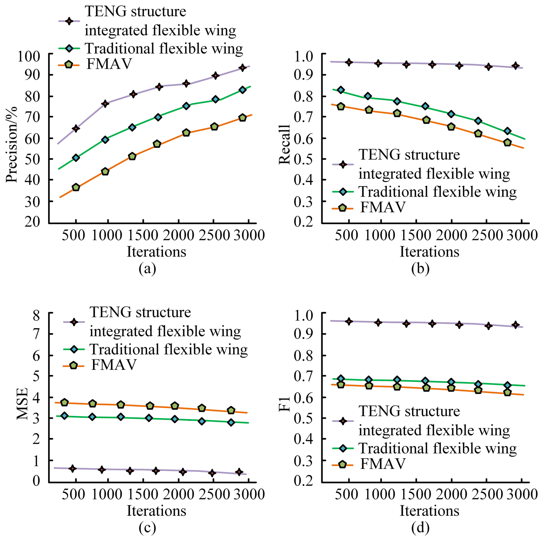
Figure 7Comparison of wing friction and energy recovery of different FAVs. (a) Precision, (b) recall, (c) MSE, (d) F1 score.
Subsequently, by comparing the precision, recall, mean square error (MSE), and F1 score of algorithms with different structures, the energy recovery performance of different flapping-wing aircraft can be indirectly evaluated. Algorithms with higher precision and recall may be more effective in controlling the motion of flapping-wing aircraft, thereby more efficiently recovering energy. Algorithms with lower MSE may more accurately predict and control the energy recovery process, thereby improving energy recovery efficiency. The F1 score combines precision and recall, providing a balanced evaluation metric that reflects the overall performance of the algorithm in the energy recovery process. Figure 7a shows the performance of different structures in terms of algorithm precision. The precision of the TENG structure significantly improves with the increase in iterations, reaching 93.5 %, which is significantly higher than traditional flexible wings and FAVs. In Fig. 7b, the recall rate of the TENG structure remains at a high level throughout the entire iteration process, reaching 95.7 %, significantly higher than traditional flexible wings and FAVs. In Fig. 7c, the MSE value of the TENG structure consistently remains at a low level, with an average MSE of 0.72, significantly lower than that of traditional flexible wings and FAV. In Fig. 7d, the F1 score of the TENG structure remains at a high level throughout the iteration process, with an average F1 score of 95.4 %, significantly higher than traditional flexible wings and FAVs. These conclusions indicate that the flexible wing integrated the integrated TENG structure has significant advantages in upward aerodynamic energy recovery and can more effectively improve energy utilization efficiency.
3.2 Simulation and practical application analysis of the FAV-ESCM
To further evaluate the performance of the FAV-ESCM, simulation experiments are conducted using MATLAB/Simulink. The aerodynamics on the wing, deformation of the flexible wing structure, and contact separation behavior of the TENG layer are simulated. Periodic boundary conditions are applied to simulate attitude control. The experiment also introduces FAV with ordinary FWT, whose wing materials include parylene-c, Mylar, polyimide film, acetate fiber film, flexible polyvinyl chloride, etc. Firstly, the energy conversion efficiency of two flapping-wing aircraft in fully closed, semi-open, open, and semi-closed states is compared, and the results are shown in Table 2.
Table 2Comparison of energy conversion efficiency under different motion states.
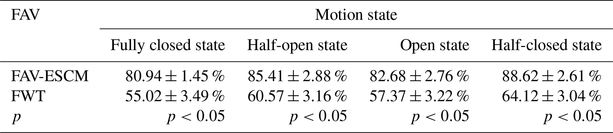
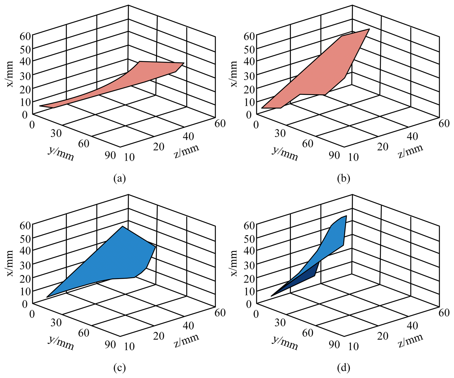
Figure 8Flexible deformation detection results of FAVs with different flexible-wing technologies. (a) T=0.1 (FAV combined with FWT), (b) T=0.6 (FAV combined with FWT), (c) T=0.1 (FAV combined with TENG structure and FWT), (d) T=0.6 (FAV combined with TENG structure and FWT).
Table 2 shows that due to the optimized contact and separation of the TENG layer, FAV-ESCM exhibits higher energy conversion efficiency than traditional FWT in all four motion states, and the difference is statistically significant (p<0.05). The energy conversion efficiency of the FAV-ESCM in the semi-closed state is 88.62 ± 2.61 %, significantly higher than the traditional FWT's 64.12 ± 3.04 % (p<0.05). The results show that the FAV-ESCM can effectively control the wing-flapping frequency based on the actual flight environment, thereby achieving stable energy output. The experimental advancement compares the wing deformation during FAV motion combining TENG structure and FWT, as shown in Fig. 8.
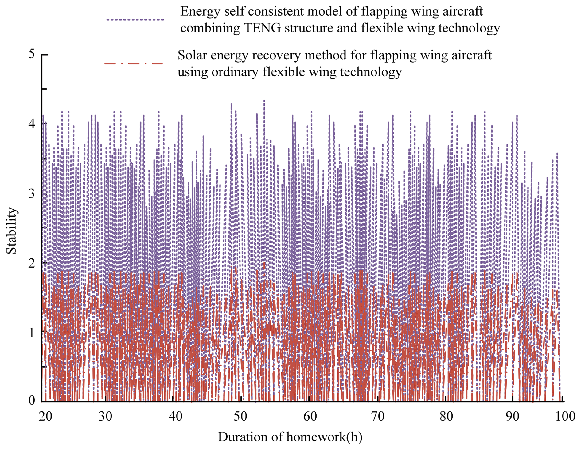
Figure 8a and b represent the wing deformation of a regular FWT FAV at different operating times. Figure 8c and d show the wing deformation of the proposed FAV combined with the TENG structure and FWT. From Fig. 8a and b, during the energy ring energy self-consistency of FWT FAV, the deformation amplitude of the wing surface along the span direction gradually increases, and the flexible deformation amplitude at T=0.1 is 10 mm. From Fig. 8c and d, the proposed FAV-ESCM exhibits a more natural deformation degree of the flexible wing when performing energy ring energy self-consistency, showing a flexible and variable state. The flexible deformation amplitude at T=0.1 is 37 mm, which is 270 % higher than FWT FAV. This indicates that the designed FAV flexible wing can maintain regular frictional deformation at any time. This will seriously affect the amount of energy recovery and output, as well as the operational efficiency of the aircraft. To verify the energy self-consistent actual energy recovery effect of the FAV-ESCM, the experiment places both the optimized and pre-optimized FAVs on the road surface of the school teaching area, and sets the experimental time to 100 h. Two types of FAVs need to pass through the same route and perform obstacle avoidance flight on campus, which involves slow stopping, lifting, acceleration, rotation, and other states. The energy recovery effects of the two types of aircraft are shown in Fig. 9.
In Fig. 9, the FAV-ESCM maintains stable energy output throughout the entire testing process, with an average power output of 40.5 ± 2.2 mW and a stability index of 3.5. The average power output of FWT FAV is 29.6±3.4 mW, with a stability index of 1.8, significantly lower than FAV-ESCM (p<0.05). The energy output of the control group is significantly lower and less stable, which proves the long-term reliability and effectiveness of the TENG-integrated energy harvesting system. This indicates that by ensuring energy self-supply and high stability, the ESCM can significantly improve the operational efficiency of FAVs, enabling them to perform tasks in longer and more complex environments. In addition, the efficient energy recovery and utilization capability of this model helps reduce dependence on external energy and promotes sustainable development and environmental protection.
Small aircraft typically require a stable energy supply to sustain their flight and perform missions. Traditional energy supply methods suffer from issues such as weight, battery life, and environmental pollution. Therefore, finding new, efficient, and environmentally friendly energy supply methods is of great significance for the development of small aircraft. This study proposes an FAV-ESCM that combines a TENG structure with FWT to improve the energy utilization of FAVs. In the experiment, the energy output of different peak voltages over time remained relatively stable at two wing-flapping frequencies of 20 and 16 Hz. At a frequency of 16 Hz, the peak voltage of 500 V produced the highest energy output, while 300 V produced the lowest. At angles of attack of 15 and 30°, the effect of different flow velocities (0.5–3.5 m s−1) on energy output showed a decreasing trend. At flow rates of 1.5 and 3.5 m s−1, the energy output showed a decreasing trend as the angle of attack increased. At 3.5 m s−1, the decrease in energy output with increasing angle of attack was relatively small, indicating that the energy output of the FAV was less sensitive to changes in angle of attack at higher flow velocities.
The results show the following. (1) The proposed FAV-ESCM combining the TENG structure and FWT can significantly improve the energy utilization efficiency of flapping-wing aircraft and extend their endurance. (2) This ESCM helps to reduce the dependence of flapping-wing aircraft on external energy sources, making the aircraft more flexible in various scenarios. (3) The research results provide an efficient and environmentally friendly solution for the energy supply of flapping-wing aircraft, reducing dependence on traditional fossil fuels. (4) The model can maintain good energy recovery performance under different frequencies, flow rates, and angles of attack, which verifies its effectiveness.
The research results are similar to some existing studies in the FWT field. Zheng et al. (2023) proposed a locally adaptive TENG-integrated wing structure. They found that the structure can stably perceive parameters such as flapping frequency and flapping angle, which helps to further enhance the intelligent airborne wing state perception capability of biomimetic flying robots. Tao et al. (2021) utilized TENG to collect energy from the deformed wings of uncrewed aerial vehicles, effectively converting the flapping energy of ailerons into electrical energy, which has broad application prospects in dynamic flapping systems. Although silk protein and silver nanowires are relatively expensive, optimized design can reduce the amount of silk protein and silver nanowires used while ensuring structural integrity and functional implementation. Therefore, it is entirely possible to display physical photos of TENG-integrated wings in future work. However, the experiment was only conducted in simulation and did not fully consider the complex and ever-changing natural environmental factors in practice, which may lead to deviations between the experimental results and the actual application situation. For the sake of computational convenience, certain physical phenomena of flapping-wing aircraft were simplified and assumed during the modeling process. Therefore, future research requires further testing in real environments and comparison with laboratory data to further optimize model parameters and structural design. In addition, more advanced numerical simulation methods and experimental techniques can be utilized to conduct in-depth research on the aerodynamic characteristics and material mechanical behavior of flapping-wing aircraft.
| FAVs | Flapping-wing aerial vehicles |
| ESCM | Energy self-consistent model |
| TENGs | Triboelectric nanogenerators |
| DC | Direct current |
| FAV-ESCM | FAV energy self-consistent model |
| FWT | Flexible-wing technology |
| PTFE | Polytetrafluoroethylene |
| MSE | Mean square error |
The datasets generated and/or analyzed during the current study are available from the corresponding author on reasonable request. No custom code was used in this study.
GZ conceptualized the study, conducted the experiments, analyzed the data, and drafted the manuscript. ZL contributed to data analysis, experimental setup, and manuscript revisions. Both authors read and approved the final paper.
The contact author has declared that none of the authors has any competing interests.
Publisher’s note: Copernicus Publications remains neutral with regard to jurisdictional claims made in the text, published maps, institutional affiliations, or any other geographical representation in this paper. While Copernicus Publications makes every effort to include appropriate place names, the final responsibility lies with the authors.
This research was supported by the project “Research on Signal Availability Evaluation and Navigation Demonstration Application Based on Beidou Satellite-Based Enhancement System” (grant no. ZJ2023-014).
This research was supported by the project “Research on Signal Availability Evaluation and Navigation Demonstration Application Based on Beidou Satellite-Based Enhancement System” (grant no. ZJ2023-014).
This paper was edited by Liangliang Cheng and reviewed by Chunlei He and three anonymous referees.
Ahmad, D., Parancheerivilakkathil, M. S., Kumar, A., Goswami, M., Ajaj, R. M., Patra, K., Jawaid, M., Volokh, K., and Zweiri, Y.: Recent developments of polymer-based skins for morphing wing applications, Polym. Test., 135, 108463, https://doi.org/10.1016/j.polymertesting.2024.108463, 2024.
Aliabadi, S. K., Parsa, M. R., and Moghadam, M. M.: Experimental study of flapping-wing aerodynamic coefficients and landing performance estimation, Meccanica, 58, 711–726, https://doi.org/10.1007/s11012-023-01644-7, 2023.
Chattaraj, N. and Ganguli, R.: Mechatronic approaches to synthesize biomimetic flapping-wing mechanisms: a review, Int. J. Aeronaut. Space, 24, 105–120, https://doi.org/10.1007/s42405-022-00527-7, 2023.
Choi, D., Lee, Y., Lin, Z. H., Cho, S., Kim, M., Ao, C. K., Soh, S., Sohn, C., Jeong, C. K., Lee, J., Lee, M., Lee, S., Ryu, J., Parashar, P., Cho, Y., Ahn, J., Kim, I. D., Jiang, F., Lee, P. S., Khandelwal, G., Kim, S. J., Kim, H. S., Song, H. C., Kim, M., Nah, J., Kim, W., Menge, H. G., Park, Y. T., Xu, W., Hao, J., Park, H., Lee, J. H., Lee, D. M., Kim, S. W., Park, J. Y., Zhang, H., Zi, Y., Guo, R., Cheng, J., Yang, Z., Xie, Y., Lee, S., Chung, J., Oh, I. K., Kim, J. S., Cheng, T., Gao, Q., Cheng, G., Gu, G., Shim, M., Jung, J., Yun, C., Zhang, C., Liu, G., Chen, Y., Kim, S., Chen, X., Hu, J., Pu, X., Guo, Z. H., Wang, X., Chen, J., Xiao, X., Xie, X., Jarin, M., Zhang, H., Lai, Y. C., He, T., Kim, H., Park, I., Ahn, J., Huynh, N. D., Yang, Y., Wang, Z. L., Baik, J. M., and Choi, D.: Recent advances in triboelectric nanogenerators: From technological progress to commercial applications, ACS Nano, 17, 11087–11219, https://doi.org/10.1021/acsnano.2c12458, 2023.
Cui, S., Zhou, L., Liu, D., Li, S., Liu, L., Chen, S., Zhao, Z., Yuan, W., Wang, Z. L., and Wang, J.: Improving performance of triboelectric nanogenerators by dielectric enhancement effect, Matter, 5, 180–193, https://doi.org/10.1016/j.matt.2021.10.019, 2022.
Fu, Y., Shi, J., and Lyu, Y.: Finite-time observer based predefined-time aircraft attitude tracking control, Int. J. Control Autom., 21, 3757–3766, https://doi.org/10.1007/s12555-021-0596-9, 2023.
Gayango, D., Salmoral, R., Romero, H., Carmona, J. M., Suarez, A., and Ollero, A.: Benchmark evaluation of hybrid fixed-flapping wing aerial robot with autopilot architecture for autonomous outdoor flight operations, IEEE Robot. Autom. Lett., 8, 4243–4250, https://doi.org/10.1109/LRA.2023.3280753, 2023.
Guo, Q., He, X., Wang, Z., and Wang, J.: Effects of wing flexibility on aerodynamic performance of an aircraft model, CJA, 34, 133–142, https://doi.org/10.1016/j.cja.2021.01.012, 2021.
Huang, H., He, W., Wang, J., Zhang, L., and Fu, Q.: An all servo-driven bird-like flapping-wing aerial robot capable of autonomous flight, IEEE/ASME T. Mech., 27, 5484–5494, https://doi.org/10.1109/TMECH.2022.3182418, 2022.
Kim, W. G., Kim, D. W., Tcho, I. W., Kim, J. K., Kim, M. S., and Choi, Y. K.: Triboelectric nanogenerator: Structure, mechanism, and applications, ACS Nano, 15, 258–287, https://doi.org/10.1021/acsnano.0c09803, 2021.
Li, Q., Ji, A., Shen, H., Li, R., Liu, K., Zheng, X., Shen, L., and Han, Q.: Experimental study on the wing parameter optimization of flapping-wing aircraft based on the clap-and-fling mechanism, Int. J. Aeronaut. Space, 23, 265–276, https://doi.org/10.1007/s42405-022-00445-8, 2022.
Ozaki, T., Ohta, N., Jimbo, T., and Hamaguchi, K.: A wireless radiofrequency-powered insect-scale flapping-wing aerial vehicle, Nat. Electron., 4, 845–852, https://doi.org/10.1038/s41928-021-00669-8, 2021.
Ozaki, T., Ohta, N., Jimbo, T., and Hamaguchi, K.: Takeoff of a 2.1 g fully untethered tailless flapping-wing micro aerial vehicle with integrated battery, IEEE Robot. Autom. Lett., 8, 3574–3580, https://doi.org/10.1109/LRA.2023.3269319, 2023.
Pan, Y., Guo, S., and Huang, X.: Research progress on bio-inspired flapping-wing rotor micro aerial vehicle development, J. Bionic Eng., 21, 1621–1643, https://doi.org/10.1007/s42235-024-00521-7, 2024.
Shinde, S. D. and Upadhyay, S. H.: The novel design concept for the tensioning system of an inflatable planar membrane reflector, Arch. Appl. Mech., 91, 1233–1246, https://doi.org/10.1007/s00419-020-01841-w, 2021.
Tao, K., Chen, Z., Yi, H., Zhang, R., Shen, Q., Wu, J., Tang, L., Fan, K., Fu, Y., Miao, J., and Yuan, W.: Hierarchical honeycomb-structured electret/triboelectric nanogenerator for biomechanical and morphing wing energy harvesting, Nano-Micro. Lett., 1, 123, https://doi.org/10.1007/s40820-021-00644-0, 2021.
Terze, Z., Pandža, V., Kasalo, M., and Zlatar, D.: Optimized flapping wing dynamics via DMOC approach, Nonlinear Dynam., 103, 399–417, https://doi.org/10.1007/s11071-020-06119-y, 2021.
Wang, H., Cheng, J., Wang, Z., Ji, L., and Wang, Z. L.: Triboelectric nanogenerators for human-health care, Sci. Bull., 66, 490–511, https://doi.org/10.1016/j.scib.2020.10.002, 2021.
Wang, T., He, X., Yao, Z., Qiang, F., and Wei, H.: Research progress on the flight control of flapping-wing aerial vehicles, Chinese J. Eng., 45, 1630–1640, https://doi.org/10.13374/j.issn2095-9389.2022.12.24.001, 2023.
Wang, W., Yang, D., Yan, X., Wang, L., Hu, H., and Wang, K.: Triboelectric nanogenerators: The beginning of blue dream, Front. Chem. Sci. Eng., 17, 635–678, https://doi.org/10.1007/s11705-022-2271-y, 2023.
Wu, X., He, W., Wang, Q., Meng, T., He, X., and Fu, Q.: A long-endurance flapping-wing robot based on mass distribution and energy consumption method, IEEE T. Ind. Electron., 70, 8215–8224, https://doi.org/10.1109/TIE.2022.3213905, 2022.
Xiao, X., Chen, G., Libanori, A., and Chen, J.: Wearable triboelectric nanogenerators for therapeutics, Trends Chem., 3, 279–290, https://doi.org/10.1016/j.trechm.2021.01.001, 2021.
Xie, C., Gao, N., Meng, Y., Wu, Y., and Yang, C.: A review of bird-like flapping wing with high aspect ratio, Chinese J. Aeronaut., 36, 22–44, https://doi.org/10.1016/j.cja.2022.06.009, 2023.
Xu, C., Yu, J., Huo, Z., Wang, Y., Sun, Q., and Wang, Z. L.: Pursuing the tribovoltaic effect for direct-current triboelectric nanogenerators, Energ. Environ. Sci., 16, 983–1006, https://doi.org/10.1039/D2EE04019K, 2023.
Xu, G., Li, C., Chen, C., Fu, J., Hou, T., and Zi, Y.: Dynamics of triboelectric nanogenerators: a review, Int. J. Mech. Syst. Dynam., 2, 311–324, https://doi.org/10.1002/msd2.12058, 2022.
Yousaf, R., Shahzad, A., Qadri, M. M., and Javed, A.: Recent advancements in flapping mechanism and wing design of micro aerial vehicles, P. I. Mech. Eng. C-J. Mec., 235, 4425–4446, 2021.
Zhang, L., Cai, H., Xu, L., Ji, L., Wang, D., Zheng, Y., Feng, Y., Sui, X., Guo, Y., Guo, W., Zhou, F., Liu, W., and Wang, Z. L.: Macro-superlubric triboelectric nanogenerator based on tribovoltaic effect, Matter, 5, 1532–1546, https://doi.org/10.1016/j.matt.2022.02.021, 2022.
Zhang, S., Bick, M., Xiao, X., Chen, G., Nashalian, A., and Chen, J.: Leveraging triboelectric nanogenerators for bioengineering, Matter, 4, 845–887, https://doi.org/10.1016/j.matt.2021.01.006, 2021.
Zhao, M., Zhang, X., Fu, Q., Zhang, C., and He, W.: Research progress on the energy consumption of bionic flapping-wing aerial vehicles, Chinese J. Eng., 44, 2111–2123, https://doi.org/10.13374/j.issn2095-9389.2022.05.17.003, 2022.
Zhao, P., Li, B., Li, Y., Liu, J., Wu, P., Gu, Z., Cheng, L., Wang, T., and Chen, H.: Visual modulation of the flexible morphing wing pose utilizing pure shear dielectric elastomer and stretchable photonic crystal, Adv. Opt. Mater., e01017, https://doi.org/10.1002/adom.202501017, 2023.
Zheng, H., Zeng, X., Wang, Y., Wang, Z., and Zhang, X.: Nanogenerator based self-powered motion monitoring for flapping wings of bio-inspired flying robots, APL, 123, https://doi.org/10.1063/5.0158287, 2023.