the Creative Commons Attribution 4.0 License.
the Creative Commons Attribution 4.0 License.
 | 22 Jan 2025
Pneumatic gripping system based on airflow proximity sensing and a self-feedback principle
Yixiao Ni
Qing Ouyang
Jiahui Peng
In pneumatic systems, the airflow circuit is both a driving source and a carrier of pressure, flow, and other information elements. In response to relying on electronic sensors and controllers to achieve closed-loop control in pneumatic systems, a theory of airflow proximity sensing and self-feedback drive was proposed to achieve closed-loop control. Based on the principle of airflow sensing, a new airflow proximity sensor was designed and studied. The structure was optimized using ANSYS software, and proximity sensing was achieved by increasing the pressure at the feedback port as the object approached. A self-feedback grasping pneumatic grasper was designed. The experimental results showed that the maximum grasping mass was 2.8 kg when the gas supply pressure was 0.1 MPa. The gripper could automatically sense and perform the grasping operation when it was close to the object.
- Article
(10152 KB) - Full-text XML
- BibTeX
- EndNote


The pneumatic gripping system is one of the most widely used systems in industry, which is applied in scenarios such as material handling, workpiece transfer, part assembly, and so on. A closed-loop controlled pneumatic gripping system should comprise multiple components, including actuators (such as jaws and suction cups), sensors (such as position and contact sensors), and controllers. Currently, pneumatic gripping end pieces widely relied on electronic sensors to detect the distance from the gripped object and determine contact, making the system complex.
However, in pneumatic systems, the airflow circuit serves as both the actuator's driving source and a means of sensing and transmitting signals (pressure, flow rate, etc.). The latter ability has been overlooked, leading to reliance on electronic sensors for closed-loop control. Research on airflow sensing and self-feedback actuation has been limited. The suction-based tactile device studied in Makino et al. (2003) utilized negative pressure to generate tactile perception but with low resolution. Back-pressure pneumatic sensors (Wang et al., 2008; Ning et al., 2012) exhibited a continuous pressure change from negative to positive at the vacuum end when an object blocked the outlet, offering high measurement accuracy but with a narrow measurement range. An airflow-sensing soft gripper designed by Dou (2023), using a de Laval nozzle structure, could automatically grip objects but had low load capacity. Reflective pneumatic sensors (Zhu, 2010; Shi, 2020) had a larger measurement range but lower accuracy, with only positive pressure at the feedback port. Yang et al. (2017) developed a pneumatic soft chamber sensor made of silicone rubber (Yang et al., 2017), which changed its internal pressure when deformed by an external force, enabling real-time position/force control in grippers (Tawk et al., 2020). Wu et al. (2022) created an umbrella-structured soft gripper with an array of soft nozzles for adhering to object surfaces (Wu et al., 2022), sensing the size of the gripped object through flow changes when the soft suction cups were obstructed. Sun et al. (2009) studied the mechanical response and tactile perception mechanism of pneumatic nozzle-based tactile interface devices under multipoint dynamic pressure loads (Sun et al., 2009). These studies have focused on the sensing field without considering its ability to act as a driving force.
Some scholars have applied airflow sensing for intelligent control of soft grippers. Rothemund et al. (2018) designed a pneumatic bistable soft valve that closed the soft gripper by switching operating modes upon object contact (Rothemund et al., 2018). Pal et al. (2020) utilized elastic energy storage principles to design a Venus flytrap-inspired gripper that releases stored pneumatic pressure upon contact to achieve closure (Pal et al., 2020). Partridge and Conn (2020) designed a microswitch within an air tube that opened the valve upon contact and compression, completing the gripping operation. These studies utilized the physical properties of airflow to achieve self-feedback actuation for intelligent gripping upon contact, but the process was irreversible, requiring manual resetting and limiting their application prospects.
In summary, current pneumatic sensors utilize the physical quantities of airflow for non-contact measurements but lack self-feedback actuation capabilities, while some pneumatic devices with self-feedback functions have only simple functionalities and limited usage scenarios. Therefore, research on airflow proximity sensing, self-feedback actuation mechanisms, and implementation methods (integrating pneumatic sensing, pressure control, and feedback actuation) to enable pneumatic systems to autonomously respond to external mechanical signals with continuous actuation is a topic of significant engineering importance. It could simplify pneumatic gripping systems and achieve gripping processes independent of electronic control.
In this paper, we designed a novel reflective airflow proximity sensor, studied its input–output characteristics, and applied it to a self-feedback pneumatic gripper. There was a novelty in the pneumatic system control: the gripper possessed the ability to autonomously sense and grip objects as they approached without electronic sensors or controllers.
The paper is organized as follows. Section 2 describes the structure optimization and experimental results of the airflow proximity sensor. In Sects. 3 and 4, the design of the self-feedback pneumatic gripper is outlined, and experiments on the grasping effect of different objects are conducted. Section 5 presents the conclusions and future work.
2.1 Structure of the airflow proximity sensor
Airflow proximity sensing uses compressed air flow as a medium, which is released onto the surface of an object through a nozzle. Some gas will flow into the feedback channel after reflection, causing changes in pressure or flow rate inside the feedback chamber. The distance changes between the sensor and the object, as well as whether they are in contact, can be detected, thereby transforming the changes in object spacing into changes in airflow parameters.
Figure 1Principle of airflow proximity sensing: (a) principle, (b) structure; 1 – annular chamber, 2 – nozzle, 3 – receiving port, 4 – feedback chamber, 5 – feedback port, 6 – supply port.
The fundamental structure and operating principle of the proximity sensor, rooted in airflow reflection, are depicted in Fig. 1a. Supply air is expelled from the annular nozzle via the annular emission chamber. In the absence of objects or when objects are distant, the jet airflow does not enter the receiving port, maintaining the feedback chamber's pressure at approximately atmospheric level. As an object approaches the nozzle, a segment of the airflow is reflected by the object's surface, entering the feedback chamber through the receiving port and elevating its pressure. The nearer the object, the greater the quantity of reflected air; thus, the resultant pressure rises in the feedback chamber, which intensifies with decreasing distance. By designing specific flow channels and harnessing the feedback chamber's pressure, it is possible not only to measure the object's distance but also to activate subsequent actuators, endowing them with the capability to autonomously sense and respond to object proximity.
The structure of the airflow proximity sensor designed in this article is shown in Fig. 1b. The airflow supply port and feedback port are arranged perpendicular to the jet direction. The supply gas flows into the annular emission chamber and is ejected from the nozzle. When an object approaches the nozzle, some of the gas is reflected and flows into the feedback chamber through the receiving port; then it flows out through the feedback port.
To obtain the internal flow and feedback port pressure characteristics of the device, a flow channel model is constructed in the simulation software ANSYS. A cylindrical flow channel is established on the outside of the nozzle outlet to simulate the jet gas flowing out and around when an object approaches the nozzle. The mesh division and structural parameters of the flow channel are shown in Fig. 2 and Table 1.
Under the condition of supply pressure PS = 0.1 MPa, the feedback pressure is simulated preliminarily. The results are shown in Fig. 3. It can be seen that when the distance is equal to 0 mm, i.e., when the object is in full contact with the sensor, the feedback pressure reaches the supply pressure, i.e., PO=PS = 0.1 MPa. As the distance increases, the feedback pressure decreases continuously. When the object is 2 mm away from the nozzle, there is still a pressure of 20 kPa at the feedback port.

Based on the above simulation results, it can be concluded that the designed airflow proximity sensor can generate different pressures at the feedback port according to the distance from the object. If a functional relationship between feedback port pressure and distance is established and calibrated, it can be used for sensing and measuring position relationships. It can also be integrated into pneumatic systems to drive actuators using feedback pressure, achieving the integration of induction and self-feedback drive.
2.2 Optimization design
To achieve better pressure feedback performance, several internal flow channel structural parameters are selected for optimization while keeping the basic external dimensions unchanged.
2.2.1 The influence of receiving port position on feedback pressure
Keeping the diameter of the feedback chamber at 2 mm and keeping the exit angle of the annular chamber at 60°, the relative position of the receiving port is increased from 0 to 2 mm. Under the conditions of a supply pressure of 0.1 MPa and a distance between the nozzle and object of 2.5 mm, the feedback port pressure is simulated as shown in Fig. 4. When the relative position changes from 0–0.5 mm, the feedback pressure remains unchanged, reaching 20.5 kPa. Afterward, it sharply decreases as the relative position increases.
Considering practical applications, if the relative position is 0 mm, then the object contacts the nozzle and also contacts the receiving port. The airflow entering the feedback chamber will be obstructed. Therefore, a certain gap needs to be left between the receiving port and the nozzle, although the feedback port pressure could reach its maximum value when the relative position is 0–0.5 mm. Here, e = 0.5 mm is taken as the optimal value for the receiving port position.
2.2.2 The influence of feedback chamber diameter on feedback pressure
Maintaining the position of the receiving port at 0.5 mm and the exit angle of the annular chamber at 45°, the diameter of the feedback chamber is increased from 1–3 mm in sequence. Under a supply pressure of 0.1 MPa and a distance of 2.5 mm from the object, the feedback port pressure is simulated. From Fig. 5, it can be seen that the feedback port pressure increases first and then decreases with the diameter of the feedback chamber, reaching its maximum value at D3 = 1.5 mm, with a feedback pressure of 21.2 kPa. Therefore, D3 = 1.5 mm can be taken as the optimal value for the feedback chamber diameter.
2.2.3 The influence of annular chamber exit angle on feedback pressure
The exit angle of the annular chamber is increased from 45 to 70° while the position of the receiving port is kept at 0.5 mm and while the diameter of the feedback chamber is kept at 2 mm. The simulation results are shown in Fig. 6. It can be seen that the feedback port pressure increases with the increase in the annular cavity exit angle. Therefore, we take θ = 70° as the optimal value for the exit angle of the annular cavity.
Based on the analysis of the three abovementioned parameters on the feedback port pressure, a set of optimal structural parameters for the airflow proximity sensor is obtained as . Thus, a simulation model is built to compare the feedback pressure changes before and after optimization under the condition of varying distances between objects and sensors.
As shown in Fig. 7, when the distance is longer than 1 mm, the feedback pressure of the optimized sensor is higher than before optimization at the same distance. For example, before optimization, when the distance is 1.5 mm, the feedback port pressure is 17 kPa. But after optimization, it can reach this pressure at a distance of 3 mm. This indicates that the sensing ability for objects at a longer distance has been enhanced.
2.3 Proximity induction test
Owing to the intricate internal flow channel and the small size of the sensor, machining presents significant challenges. Consequently, 3D printing is employed to fabricate an airflow proximity sensor as shown in Fig. 8a, with photosensitive resin being the material of choice.
Figure 8Experimental system for airflow proximity sensor: (a) experimental sensor; (b) experimental system; 1 – digital display, 2 – supply port pressure gauge, 3 – magnetic grid ruler, 4 – mobile platform, 5 – object, 6 – feedback port pressure gauge, 7 – sensor.
The test bench shown in Fig. 8b is designed to study the characteristics of the sensor and compare it with simulation results. The sensor is fixed horizontally on the experimental bench, and the object is fixed on the moving platform. The displacement of the moving platform is controlled by rotating the screw to change the distance X between the nozzle and the object. The air is supplied to the sensor through a pressure-reducing valve. Two pressure gauges are installed at the air supply port and feedback port to record the changes in pressure with the position of the moving platform.
Under the condition of a gas supply pressure of 100 kPa, the axial movement of the mobile platform is controlled, and the pressure changes at the feedback port are measured at different distances. The results are shown in Fig. 9. As can be seen from the figure, there is a large error between the experimental value and the simulation value when the distance is 0 mm, namely, the object is in full contact with the nozzle. In the simulation case, the feedback pressure is equal to the supply pressure, while in the experiment the feedback pressure is less than the supply pressure. Although the object is in contact with the nozzle in the experiment, it cannot be completely sealed, resulting in air leakage.

When the distance is longer than 0.5 mm, the experimental value rapidly decreases and is much lower than the simulation value. The reasons might be the following. (1) Due to the complex internal structure of the device and the difficulty of mechanical processing, 3D printing is used. However, the dimensional accuracy and surface roughness of 3D printing are low and cannot be measured. (2) Simulation simplifies the flow channel and internal flow state to varying degrees, so the simulation results can only be used as a reference for changing trends.
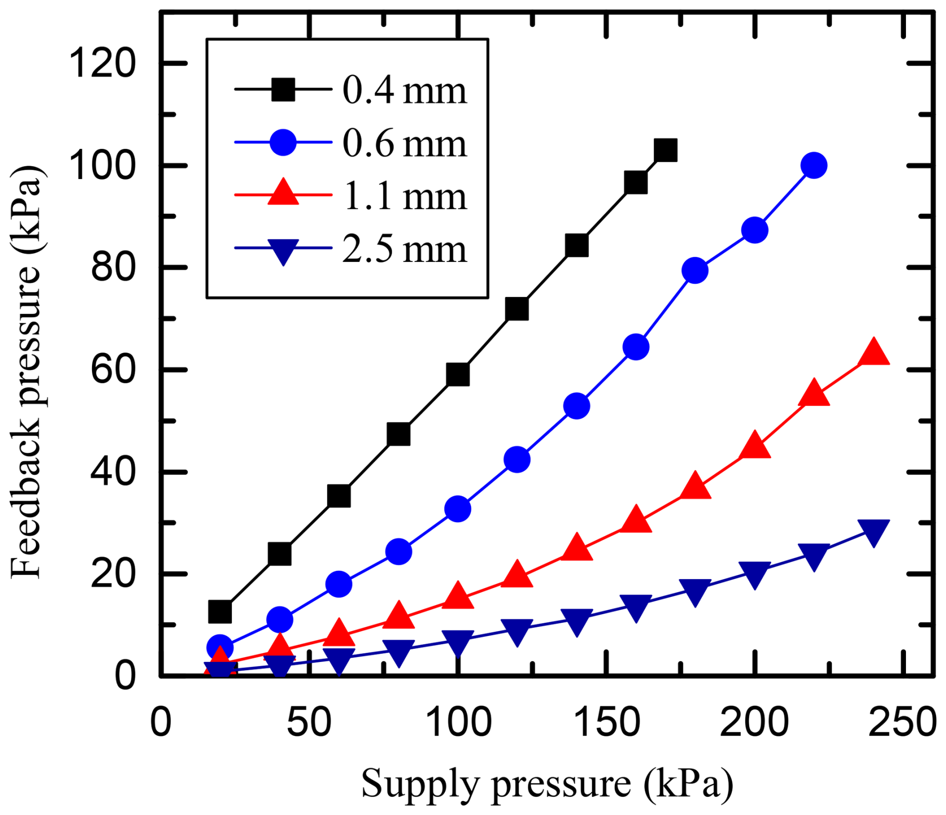
Keeping the distance between the object and the nozzle constant, the pressure state of the feedback port is tested under different supply pressures, as shown in Fig. 10. As can be seen from the figure (under the same supply pressure), the shorter the distance, the higher the pressure at the feedback port. At the same distance, the pressure at the feedback port increases with the increase of the supply pressure, and it maintains a good linear relationship.
3.1 Structure of the self-feedback pneumatic gripper
According to the airflow proximity sensor, the structure of the self-feedback pneumatic gripper was designed as shown in Fig. 11. The main body is a low-friction cylinder fixed to the base flange, and the airflow sensor is fixed to the lower part of the base flange. The end of the piston rod is connected to the top flange, while four connecting rods are connected around it. The other end of the connecting rod is connected to four clamping jaws, while the middle part of the clamping jaw is hinged on the base flange.
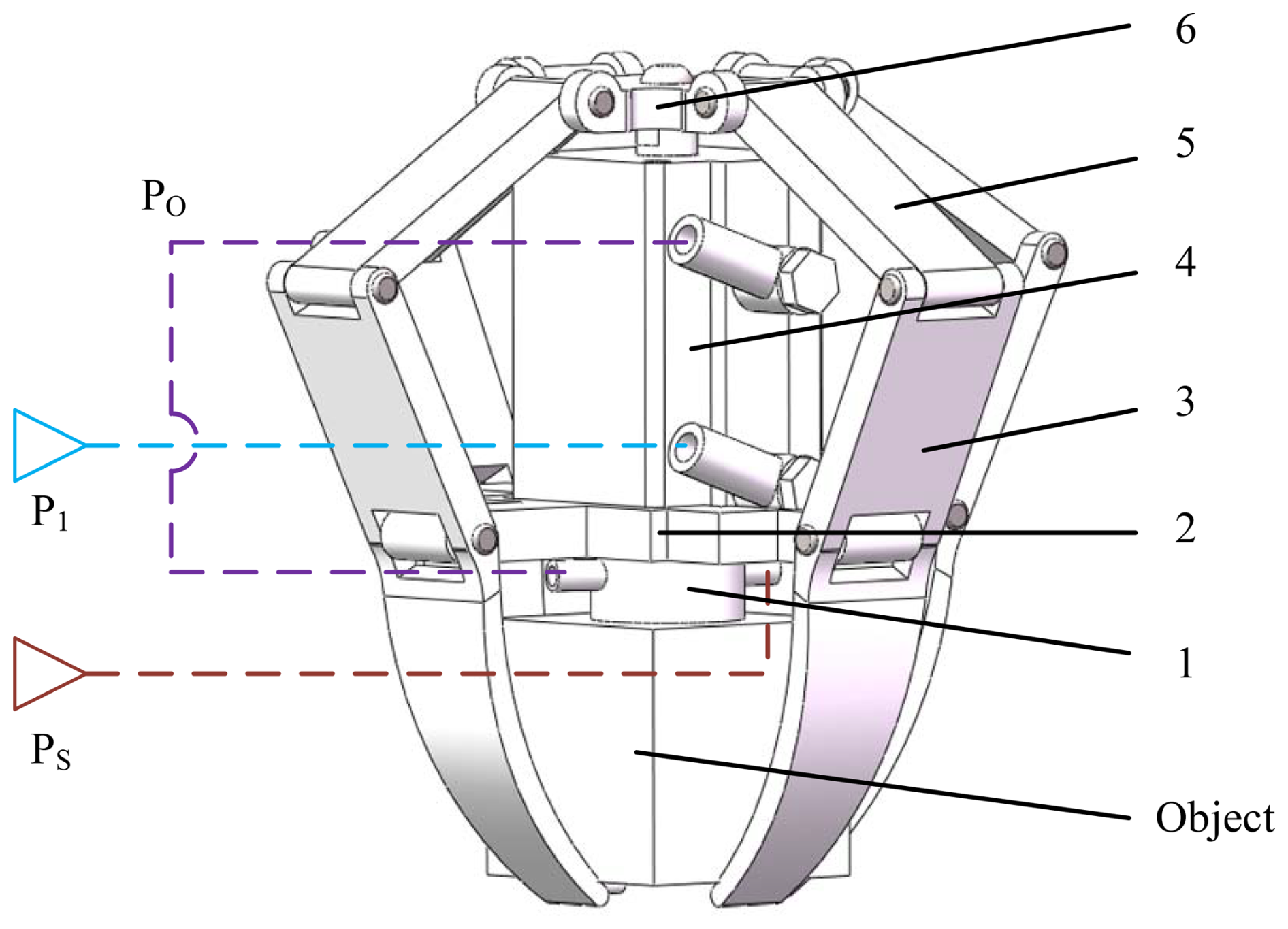
Figure 11Pneumatic circuit of clamping device: 1 – sensor, 2 – base flange, 3 – clamping jaw, 4 – cylinder, 5 – rod, and 6 – top flange.
The rodless chamber is connected to supply pressure P1. The air supply pressure PS is connected to the supply port of the sensor. The rod chamber is connected to the feedback port. PO is the feedback pressure of the feedback port. When the gripper is far away from the object, the feedback pressure is atmospheric pressure. The piston rod extends, and the jaws open when the gripper approaches the object; the feedback pressure PO increases as the distance decreases. Also, the pressure in the rodless chamber increases. When pressure PO reaches a certain value, the piston rod retracts. The clamping jaw grasps the object against the nozzle, completing the grasping action. The entire process is completed autonomously without the intervention of any electronic sensors or controllers.
3.2 Grasping force analysis
The force situation after the gripper stably grasped a 50 × 50 × 50 mm acrylic block is shown in Fig. 12. The telescopic motion of the piston rod is simplified as the translational motion of the slider, and the connecting rod and clamp are simplified as rod components without thickness. Therefore, the system is simplified as a connecting rod slider system. Since the four claws are the same, only one of them needs to be analyzed.
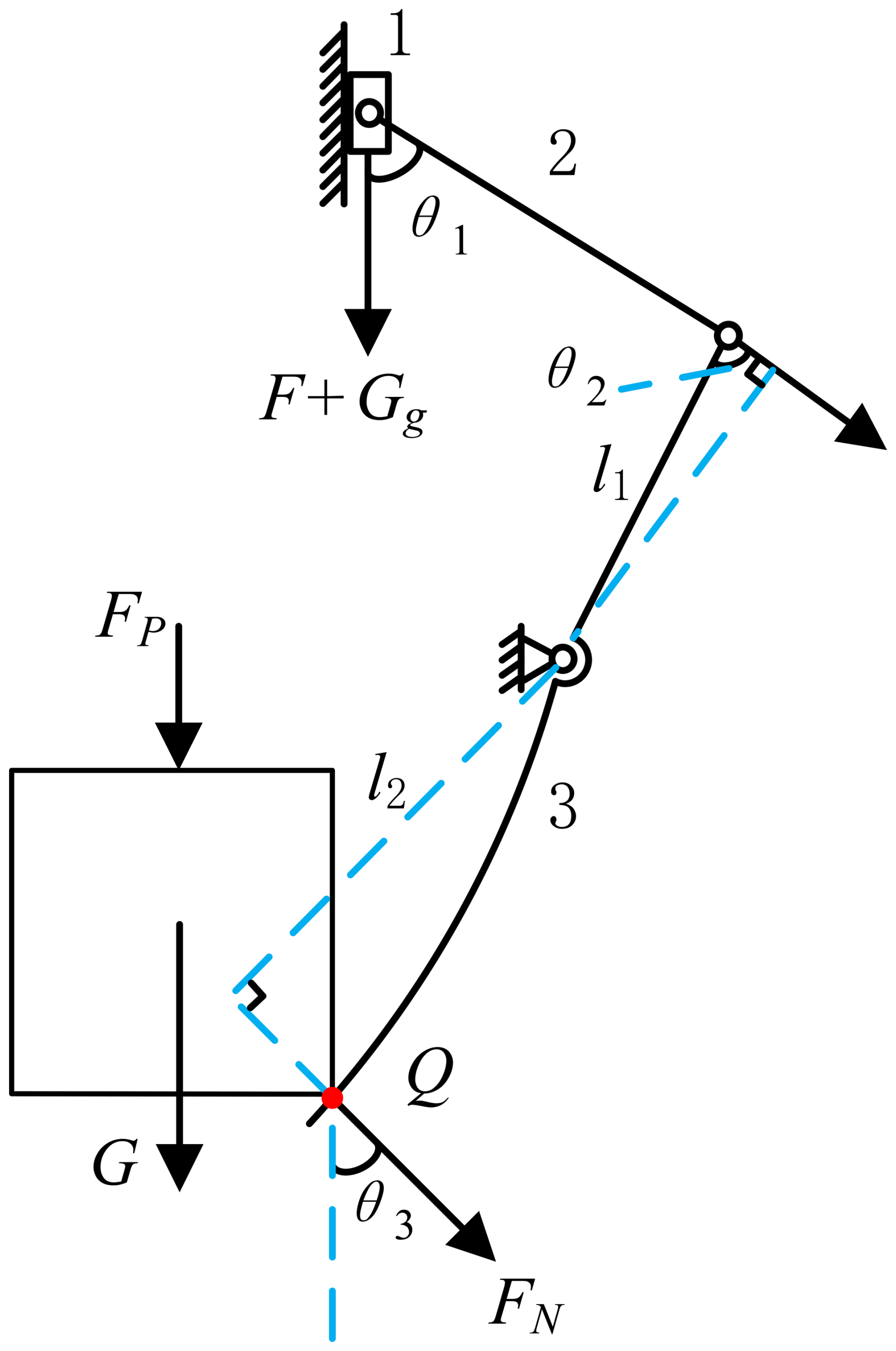
The force acting on slider 1 is the force acting on the piston rod, which is the air pressure in the two chambers of the cylinder.
where PO is the feedback pressure, P1 is the pressure in the rodless chamber, S1 and S2 are areas in the rodless chamber and the rod chamber (S1=490.6 mm2, S2=412.1 mm2), Ff is friction, and Gg is gravity of the piston and piston rod (Gg=200 g).
The bending moment generated by connecting rod 2 to connecting rod 3 is
where l1 is the length of the clamping jaw's upper arm (l1=56 mm), θ1 is the angle between the connecting rod and the vertical direction (θ1=58.4°), and θ2 is the angle between the clamping jaw's upper arm and the connecting rod (θ2=85.3°).
When the gripper grasps the acrylic block, assuming that the force FN acted on point Q, perpendicular to the gripper, and ignoring the frictional force, the resulting bending moment is
where l2 is the length of the arm of force at the point of application (l2=71 mm).
When grasping stably, the torque acting on connecting rod 3 is balanced; it could be solved as
Acrylic blocks are subjected to gravity G, gripper force FN, and pressure from the sensor, as well as air pressure FP from the nozzle. To achieve stable gripping, the pressure between the object and the sensor must be higher than 0 MPa; that is,
where S3 is the area of the nozzle, and θ3 is the angle between the force and the vertical direction (θ3=41°).
By combining Eqs. (1), (4), and (5) and ignoring friction, the minimum feedback pressure can be solved as follows:
where .
When gas supply P1 is 0.01 MPa and PS is 0.1 MPa, the feedback pressure PO can be calculated as 0.023 MPa, corresponding to a sensing distance of 0.8 mm. This means that when the distance between the acrylic block and the gripper reaches 0.8 mm, the gripper can automatically grab the acrylic block.
4.1 Grasping effect
to experimentally verify the working process and grasping effect of the self-feedback pneumatic gripper based on the airflow proximity sensor, a self-feedback grasping experimental system as shown in Fig. 13 was constructed. The gripper was fixed to the profile frame through a connecting piece, and the object being grasped directly below was placed on the up-and-down-moving platform. When the platform moves up, the distance between the object and the gripper decreases. After the airflow proximity sensor senses the object, the gripper automatically grasps the object.
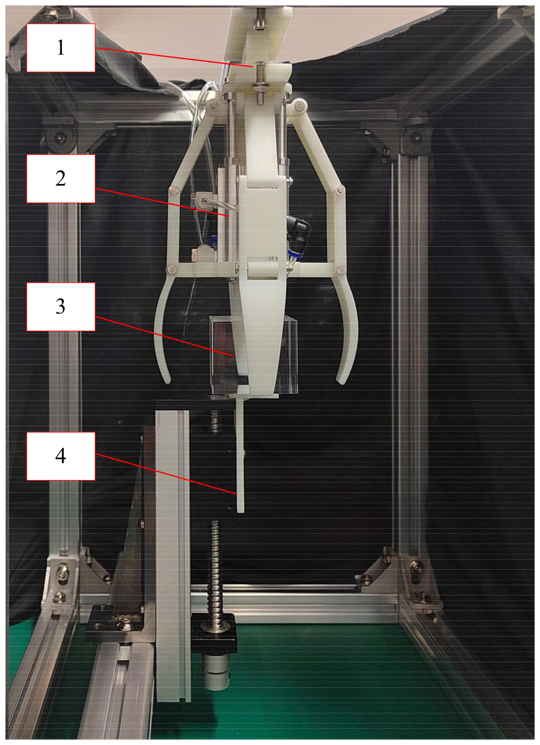
Figure 13Self-feedback grasping experimental system: 1 – connector, 2 – self-feedback pneumatic gripper, 3 – object, 4 – moving platform.

Figure 14Different object grasping effects: (a) wooden blocks; (b) acrylic block; (c) plastic balls; (d) wooden cylinder.
Objects of different shapes such as cubes, spheres, and cylinders made of different materials such as acrylic, wood, and plastic were selected. Under the conditions of supply pressure with P1 = 0.01 MPa and PS = 0.1 MPa, the grasping effect was tested, as shown in Fig. 14. As can be seen from the figure, the self-feedback pneumatic gripper could stably and reliably grasp objects of various materials and shapes.
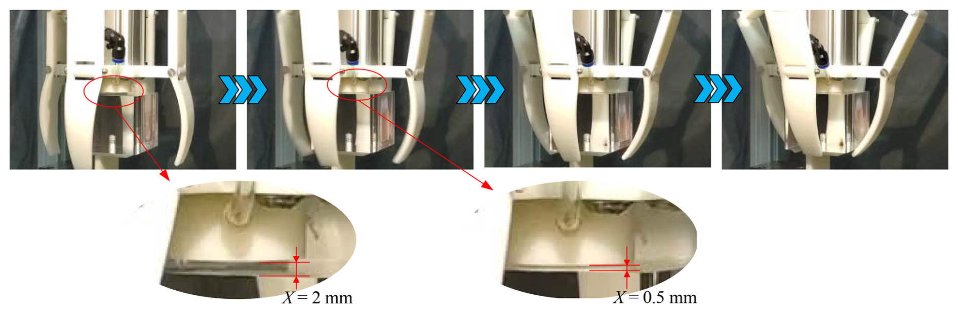
Figure 15 shows the action process of grasping the acrylic block. When the distance between the acrylic block and the nozzle was 2 mm, the pressure at the feedback port was not sufficient to drive the gripper to grasp, and the clamping jaw remained open. When the distance was reduced to 0.5 mm, the feedback pressure could overcome the initial force in the rodless chamber, and the clamping jaw began to contract. During the grasping process, the clamping jaw caused the acrylic to move upwards, bringing it closer to the nozzle. This increased the feedback pressure and clamping force, ensuring a reliable grasp. The entire action process was smooth, reliable, and autonomous.
4.2 Maximum gripping quality
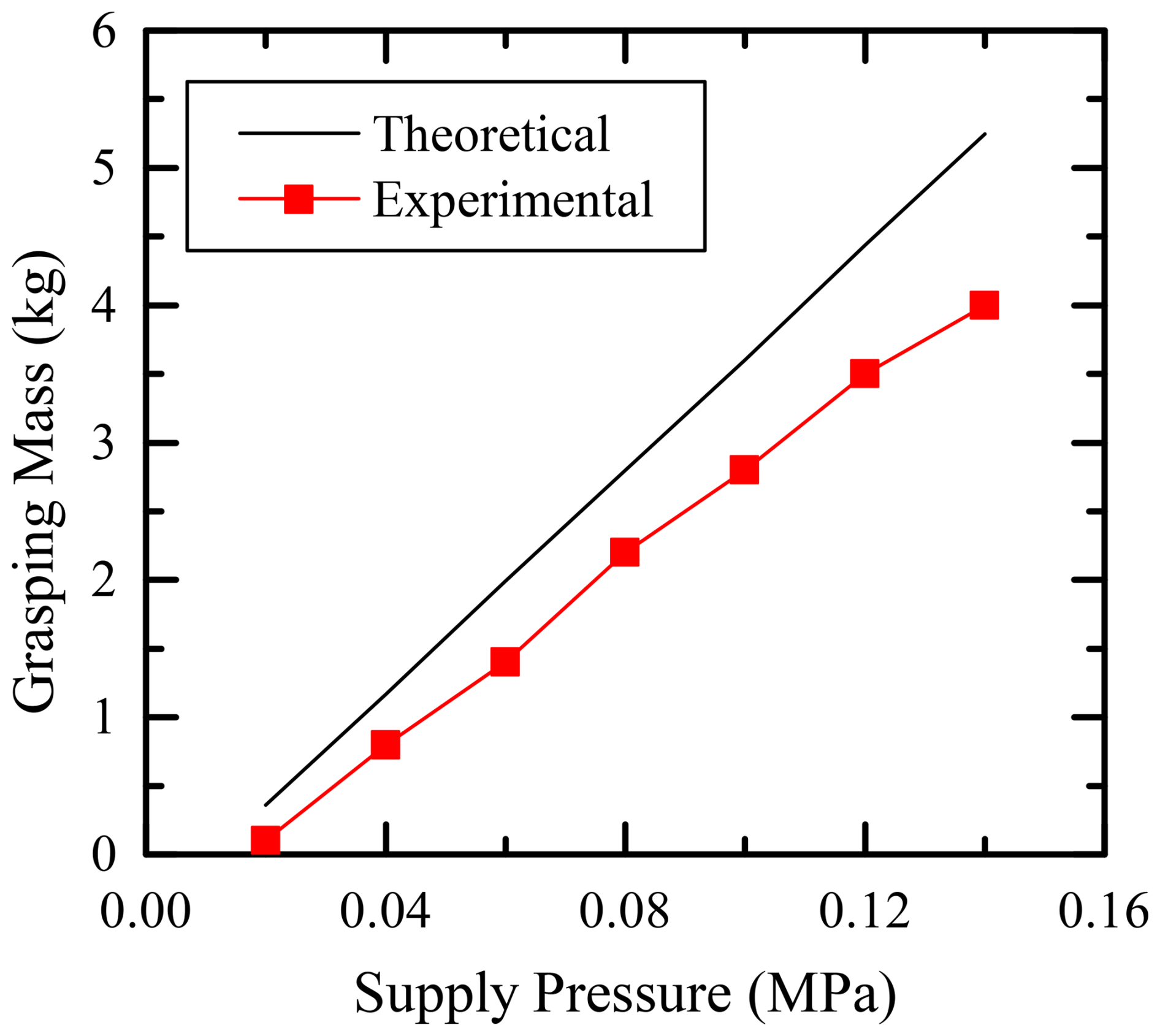
The relationship between the mass of the grasped object and the supply pressure can be obtained from Eq. (5) as follows:
In an ideal situation, when the object is in close contact with the nozzle without leakage, PO=PS. The maximum mass of the object that can be grasped is represented by Eq. (8). It can be seen that the maximum grasping mass is a linear function of the gas supply pressure PS.
The following steps were taken. Maintain a pressure of P1 = 0.01 MPa, select an acrylic block with a gripping size of 50 × 50 × 50 mm, and connect a load cell at the bottom. Drag the load cell vertically downwards, record the maximum pulling force when the grasped object is pulled away from the gripper, and calculate the maximum grasping mass. The grasping ability was tested under different air supply pressures (PS), and the results are shown in Fig. 16. In the actual grasping process, although the object is in close contact with the nozzle under the action of the gripper, it is not completely sealed and there is air leakage, so the actual maximum grasping mass is less than the theoretical calculation value.
4.3 Application scenarios
The gripper in this article can be applied to most industrial scenarios that require gripping, handling, or assembling workpieces. As shown in Fig. 17, the gripper is installed at the end of the two-axis moving platform to simulate the transportation of parts in industry. Firstly, the horizontal cylinder is operated to position the gripper directly above workstation 1. Secondly, the vertical cylinder is operated to move downwards, and the gripper approaches the acrylic block. When the distance decreases, the gripper automatically senses and grabs the acrylic block. Then, the gripper is operated directly above workstation 2. The vertical cylinder descends, and the gripper releases the block at workstation 2. The experiment completes the operation of transporting the block from workstation 1 to workstation 2.
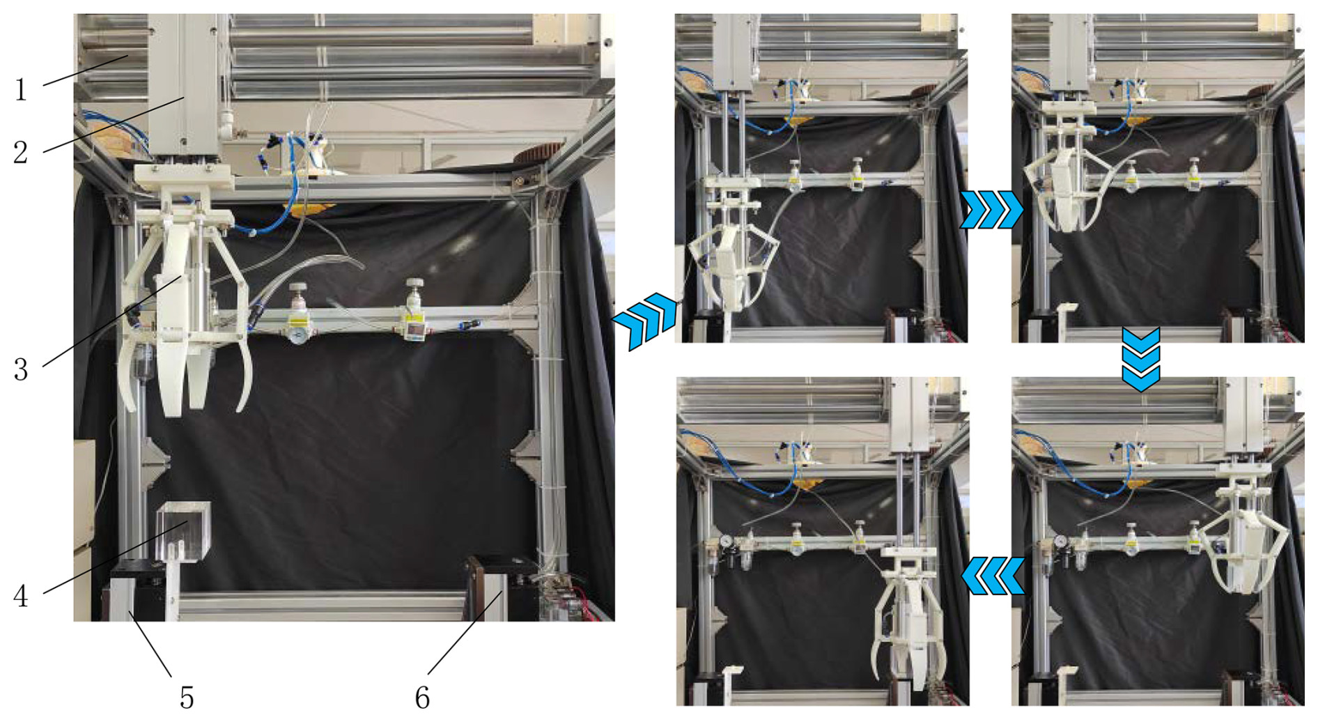
Figure 17Object handling experiment: 1 – horizontal cylinder, 2 – horizontal cylinder, 3 – gripper, 4 – object, 5 – workstation 1, 6 – workstation 2.
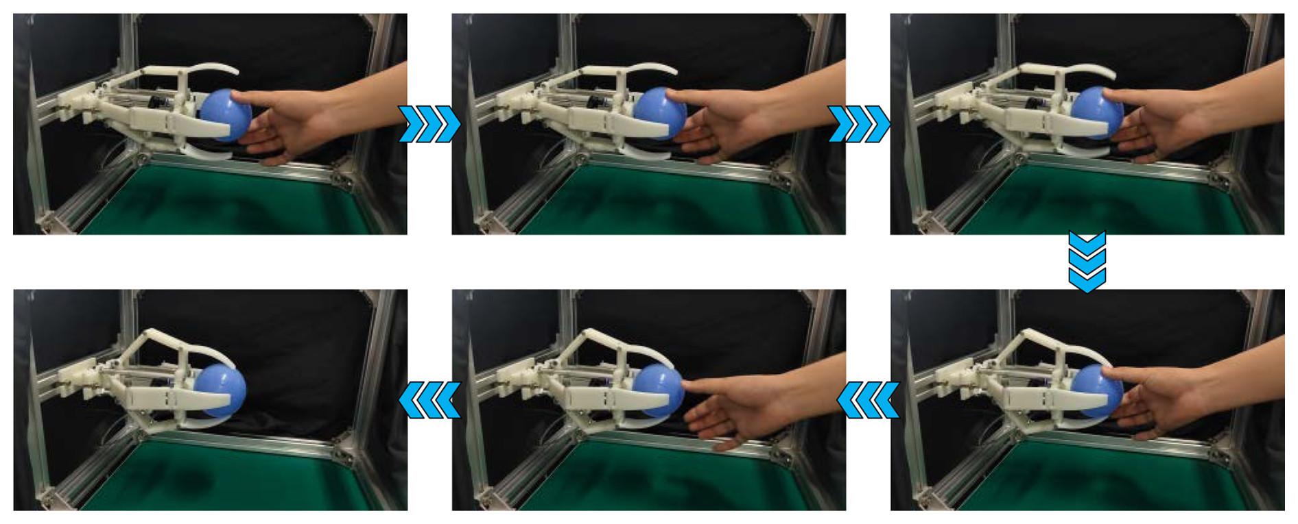
The sensor can also be used in robotic hands to complete an interaction between robots and humans. Figure 18 shows the scenes of a human transferring an object to the gripper. In the experiment, the gripper is manually handed the plastic ball. The gripper automatically completes grasping after sensing the touch. In the past, this perception is achieved through advanced electronic biosensors. But now, there is a new way of sensing and interacting with the results of this research.
At present, pneumatic systems rely on electronic sensors and controllers to achieve closed-loop control. This article proposes a self-feedback driving method based on the principle of airflow proximity induction, which provides a new solution for closed-loop control of pneumatic systems. It can also be applied to human–computer interaction scenarios such as robots and robotic arms. Some conclusions can be drawn as follows.
-
An airflow proximity sensor was proposed to address the issue of current pneumatic systems lacking self-sensing and a self-feedback drive. It can provide distance-sensing feedback, where the pressure at the feedback port increases as the distance between the nozzle and the object decreases. At the same time, it also has the ability to drive the downstream pneumatic actuator.
-
A self-feedback pneumatic gripper was developed. The experimental results demonstrate that the gripper remains open when the gripper is far away from the object. When the gripper approaches the object, the feedback pressure increases, and the gripper actively grasps the object. The entire process does not require the intervention of any electronic sensors or controllers and is completed autonomously. When the air supply pressure is 0.1 MPa, the maximum gripping mass is 2.8 kg.
-
There is a difference between the simulation results and the experimental results in Fig. 9, and some possible reasons are given in the article. In future research, we will focus on this issue. It will be valuable to have a discussion on the design tradeoffs related to the use of 3D printing for fabricating the sensor, including potential impacts on precision and durability.
The data that supports the findings of this study are available from the corresponding author (Jiabin Yang) upon reasonable request.
JY conceived the presented idea. YN and JP conducted structural design, simulation optimization, and experiments. JY and QO wrote and reviewed the paper.
The contact author has declared that none of the authors has any competing interests.
Publisher's note: Copernicus Publications remains neutral with regard to jurisdictional claims made in the text, published maps, institutional affiliations, or any other geographical representation in this paper. While Copernicus Publications makes every effort to include appropriate place names, the final responsibility lies with the authors.
The authors thank the editors and reviewers for their efforts.
This paper was edited by Zi Bin and reviewed by two anonymous referees.
Dou, M.: Design and Research of Gas Induced Soft Gripper, Nanjing University of Science and Technology, https://doi.org/10.27241/d.cnki.gnjgu.2023.002319, 2023 (in Chinese).
Makino, Y., Asamura, N., and Shinoda, H.: A Cutaneous Feeling Display Using Suction Pressure, SICE 2003 Annual Conference, Fukui, Japan, 4–6 August 2003, IEEE, 2096–2099, https://ieeexplore.ieee.org/document/1323846 (last access: 21 January 2025), 2003.
Ning, H., Du, M., Gong, J., and Li, H.: Analysis of the Flow Field in the Lord and Measuring Nozzles and Parameter Optimization of the Differential Pressure Pneumatic Gauge Based on the CFD, Machine Tool & Hydraulics, 40, 36–39, https://doi.org/10.3969/j.issn.1001-3881.2012.11.011, 2012 (in Chinese).
Pal, A., Goswami, D., and Martinez, R.: Elastic energy storage enables rapid and programmable actuation in soft machines, Adv. Funct. Mater., 30, 1906603, https://doi.org/10.1002/adfm.201906603, 2020.
Partridge, A. and Conn, A.: Passive, reflex response units for reactive soft robotic systems, IEEE Robotics and Automation Letters, 5, 4014–4020, https://doi.org/10.1109/LRA.2020.2985618, 2020.
Rothemund, P., Ainla, A., Belding, L., Preston, D. J., Kurihara, S., and Suo, Z., Whitesides G. M.: A soft, bistable valve for autonomous control of soft actuators, Science Robotics, 3, eaar7986, https://doi.org/10.1126/scirobotics.aar7986, 2018.
Shi, K.: Design of Pneumatic Sensor with Lager Measurement Range, Hefei University of Technology, https://doi.org/10.27101/d.cnki.ghfgu.2020.001415, 2020 (in Chinese).
Sun, Z., Bao, G., and Li, X.: Experiment research and analysis on pneumatic point tactile display, Journal of Dalian Maritime University, 35, 89–93, https://doi.org/10.16411/j.cnki.issn1006-7736.2009.01.029, 2009 (in Chinese).
Tawk, C., Zhou, H., Sariyildiz, E., Panhuis, Spinks, G. M., Panhuis, M., and Alici, G.: Design, modeling, and control of a 3D printed monolithic soft robotic finger with embedded pneumatic sensing chambers, IEEE-ASME T. Mech., 26, 876–887, https://doi.org/10.1109/TMECH.2020.3009365, 2020.
Wang, F., Zhang, H., Deng, S., and Niu, X.: Study on Pneumatic Sensor with High Precision, Tool Engineering, 43, 102–105, https://doi.org/10.3969/j.issn.1000-7008.2009.07.032, 2008 (in Chinese).
Wu, M., Zheng, X., Liu, R., Hou, N., Afridi, W., Afridi, R., Guo, X., Wu, J., Wang, C., and Xie, G.: Glowing Sucker Octopus (Stauroteuthis syrtensis)-Inspired Soft Robotic Gripper for Underwater Self-Adaptive Grasping and Sensing, Adv. Sci., 9, 2104382, https://doi.org/10.1002/advs.202104382, 2022.
Yang, H., Chen, Y., Sun, Y., and Hao, L.: A novel pneumatic soft sensor for measuring contact force and curvature of a soft gripper, Sensor. Actuat. A-Phys., 266, 318–327, https://doi.org/10.1016/j.sna.2017.09.040, 2017.
Zhu, J.: Research on Reflection-type Pneumatic Sensor with Large Measurement Range, Hefei University of Technology, https://doi.org/10.7666/d.y1700924, 2010 (in Chinese).