the Creative Commons Attribution 4.0 License.
the Creative Commons Attribution 4.0 License.
An anti-parallelogram ring four-array rolling mechanism with multiple rolling gaits for mobile robots
Zhiyuan Xun
Guanglong Du
Wenbo Zhu
Wei Yu
Changjiang Liu
Jun Wang
Compared with the traditional mobile robots, the new concept mobile robots have greater deformation capability and richer mobile gait; similarly, they have a better capability to adapt to the environment. This paper presents a ring four-array rolling mechanism that consists of four anti-parallelogram mechanisms with revolute joints. The mechanism is connected by four anti-parallelograms in a looped configuration and has a not-totally-closed ring shape, whose external contour is similar to that of a quadrangular prism. The mechanism has planar and spherical patterns of locomotion, in which the planar pattern of locomotion includes the parallelogram rolling gait and the anti-parallelogram tumbling gait, and the spherical pattern of locomotion includes the spherical rolling gait. On this basis, the kinematic analysis of the two patterns of locomotion is carried out to obtain the positions of each point and the center of mass (CM) of the mechanism. The feasibility of the rolling locomotion of the mechanism is verified by the moving trajectory of the CM. According to analyzing the feasibility of the mechanism's obstacle-crossing and moving strategy, the mechanism is made to complete the switch between different motion modes. Through the establishment of a dynamic model and simulation, the analysis of the rolling gait of the mechanism is completed, and a prototype is made for experimental research. The results show that the anti-parallelogram ring four-array rolling mechanism has the basic rolling capability of linear movement and steering. Furthermore, in the initial state of the mechanism, the mechanism enables flexible switching between multiple rolling gaits.
- Article
(4244 KB) - Full-text XML
- BibTeX
- EndNote
Traditional mobile robots can be classified into wheeled (Li et al., 2019; Guan and Liu, 2019; Borkar et al., 2023; Tagliavini et al., 2022), tracked (Chen et al., 2023; Sampada et al., 2023; Ugenti et al., 2023; Wang et al., 2023), and footed robots (Ding et al., 2023; Yan et al., 2022; Zhang et al., 2020; Biswal and Mohanty, 2021; Fei and Liu, 2021) in terms of their mode of movement. Among them, the rolling movement of wheeled robots is considered to be a highly efficient way of movement (Armour and Vincent, 2006) because the relationship between the rolling movement and the ground contact area is the line contact or small rectangular surface contact and the friction energy consumption in the rolling process is small, so the rolling movement has a high mobility efficiency (Amir and Mojabi, 2002; Phipps and Minor, 2006).
New concepts for mobile robots are gradually being proposed for greater environmental adaptability and obstacle-crossing performance (Li et al., 2018; Haddadin et al., 2019; Hoerner and Abbaszadeh, 2022; Zhao et al., 2023; Teng et al., 2024). Among them, whole-body-deforming mechanisms composed of parallel mechanisms, which are traditionally used as operators (Wu et al., 2008, 2010, 2013), have both moving and operating capabilities. Hamlin and Sanderson (1994) pioneered the development of a variable geometry truss with a walking capability by combining a concentric multilink spherical joint with a parallelogram mechanism, leading to the construction of tetrahedral and octahedral robots. Lee et al. (2000) and Lee and Sanderson (2002) explored a class of modular polyhedral robots with a high degree of redundancy, transitioning from planar polycyclic mechanisms to spatial mechanisms and proposing tetrahedral and icosahedral robots with the capability to roll. Lyder et al. (2008) introduced a hierarchical modular robot featuring passively retractable flexible linkage modules, actively retractable rigid linkage modules, and pintle-shaped vertex modules, allowing for shape adaptation through peristalsis to accommodate surroundings. Tian et al. (2014) explored two mobile devices based on variations of a single-parallelogram mechanism with 1 degree of freedom (DOF). The mechanisms can execute sliding and crawling motions along the ground, and the techniques of controlling the motors to change the locomotion modes and walking directions at the singular position of the mechanism can be useful in the mechanism design of mobile robots with multiple locomotion modes. Sun et al. (2019) proposed a new Bricard-like mechanism composed of three anti-parallelogram units, and the mechanism can be used as a unit to construct deployable mechanisms and deployable polyhedron mechanisms in the future due to its excellent folding performance. Liu et al. (2020) dealt with the construction of a novel family of reconfigurable deployable Bricard-like mechanisms with angulated elements (AEs). The reconfigurable dual AE unit is designed by considering the layers and sizes of links. Given the folding capability and the reassembly feasibility, these Bricard-like mechanisms can be used as modules to construct deployable polyhedral mechanisms and large deployable mechanisms in the future. Xian (2022) introduced the motion/structure mode analysis and classification of n-RR planar parallelogram mechanisms. This work provides a foundation for the construction and analysis of several variable-DOF mechanisms composed of planar parallelogram mechanisms. Moreover, modular robots (Dai et al., 2022; Uchida et al., 2019) and linkage mechanism with possible application in robotics (Li et al., 2018, 2020; Sun et al., 2023; Zhang et al., 2020) are gradually gaining prominence and advancing.
In our previous research, we proposed the concept of geometric robots which have typical geometric shape characteristics and possess a large overall deformation capability. As a consequence, geometric robots have better mobility performance. On that basis, we designed a planar four-bar mechanism the appearance of which is presented as a single parallelogram (the entity is a hollow quadrilateral and it has a quadrilateral cross section) (Liu et al., 2012). The parallelogram rolling mechanism can become tumbled by changing the CM, which can continuously roll along a linear movement is achieved by alternately fixing the articulated units, and has the capability of continuous linear movement (Xun et al., 2015; Li et al., 2017). The anti-parallelogram tumbling mechanism is similar to the parallelogram rolling mechanism, which can continuously roll along a linear movement. In addition, the anti-parallelogram tumbling mechanism has better stability and rigidity compared to the parallelogram rolling mechanism (Sun et al., 2020). The spherical four-bar rolling mechanism allows for rolling along the circumference. The axes of the revolute joints of a spherical four-bar mechanism converge at a point, and the mechanism can roll in a circumference around this point of convergence (Ma et al., 2018; Liu et al., 2012).
As we all know, the parallelogram and anti-parallelogram are typical planar four-bar mechanisms, while the spherical four-bar mechanism is a form of the spatial mechanism. The parallelogram mechanism and the anti-parallelogram mechanism can realize the forward and backward rolling and tumbling, respectively, and the spherical rolling mechanism can perform spatial rolling and rolls along a fixed arc. In this paper, we attempt to design a linkage mechanism that can integrate the characteristics of the parallelogram rolling mechanism, anti-parallelogram tumbling mechanism, and spherical four-bar rolling mechanism. Moreover, compared with our previous design of the rhombohedron rolling mechanism (Xun et al., 2016), we expect the linkage mechanism to be capable of switching flexibly in multiple rolling gaits (parallelogram rolling gait, anti-parallelogram tumbling gait, and spherical rolling gait) to obtain flexible rolling capability. By employing these capabilities, the flexibility of the mechanism can be increased, thus enhancing environmental adaptability.
2.1 Description of the mechanism
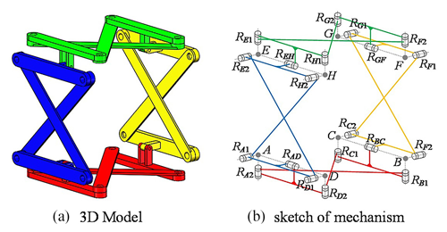
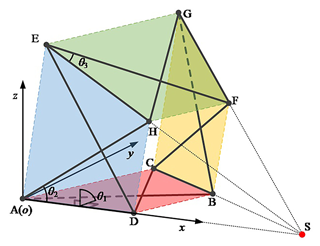
The anti-parallelogram ring four-array rolling mechanism consists of four anti-parallelogram mechanisms connected in series to form a ring; consequently, this configuration possesses the integration of multiple patterns of locomotion, and the mechanism is connected by four revolute joints (RAD, RBC, RGF, and REH), bringing the total to 16 bars and 20 revolute joints within the mechanism. Each revolute joint within the articulated plane formed by the anti-parallelogram mechanism is parallel to the others and perpendicular to the revolute joints at the ends of the articulated plane. To achieve isotropy, the outer contour of the individual anti-parallelogram mechanism is configured as a square. Consequently, all anti-parallelogram mechanisms have equal lengths of the opposite sides of the bars, defined as l1, and all cross-bars have equal lengths, measured as . The three-dimensional model of the anti-parallelogram ring four-array rolling mechanism is presented in Fig. 1.
2.2 Degree of freedom and movement pattern
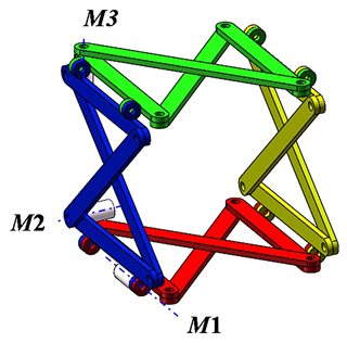
When the opposite sides of the anti-parallelogram mechanism in each articulated plane are parallel and the two adjacent articulated planes are perpendicular to each other, this state is defined as the initial state of the mechanism. In this state, the anti-parallelogram ring four-array rolling mechanism has 3 degrees of freedom. Since there are two sets of opposing articulated planes in the mechanism, in the initial state, 2 degrees of freedom actuate a set of opposing planes of the anti-parallelogram mechanism, while the remaining degree of freedom actuates the tandem formation of the parallelogram mechanism (also referred to as the large toroidal mechanism). The drive configuration of this mechanism is shown in Fig. 2.
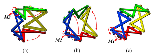
Due to the special characteristics of the mechanism composition, the anti-parallelogram ring four-array rolling mechanism has two patterns of locomotion: the planar pattern of locomotion and the spherical pattern of locomotion. The planar pattern of locomotion includes the parallelogram rolling gait and the anti-parallelogram tumbling gait. The parallelogram deformation is driven by the drive motor M1, as shown in Fig. 3, while the anti-parallelogram deformation is driven by the drive motors M2 or M3, which are shown in Fig. 3.
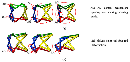
In the spherical pattern of locomotion, the four revolute joints, RAD, RBC, RGF, and REH, of the mechanism will converge at one point. The drive motors M2 and M3 actuate in concert, enabling control over the opening and closing steering angle of the mechanism. The drive motor M1 can deform the mechanism into a spherical four-bar mechanism. Figure 4a shows that the change in the opening and closing angle of the mechanism can be controlled by the drive motors M2 and M3, and this change is used by the robot to adjust the forward direction. Figure 4b shows that the spherical motion is realized by driving the motor M1, and the deformation is used for the robot to travel in the form of a spherical four-bar mechanism so as to achieve the function of changing direction.
2.3 The process of switching
The mechanism has three patterns of locomotion, including the planar pattern of locomotion (Fig. 5a), the initial state (Fig. 5b), and the spherical pattern of locomotion (Fig. 5c). The process of switching between patterns of locomotion: in the initial state, the motor M1 or M2 can be driven so that the mechanism can change from the initial state to the planar pattern of locomotion; the planar pattern of locomotion includes the parallelogram pattern of locomotion and the anti-parallelogram pattern of locomotion. By driving M1, the mechanism will roll in a parallelogram gait (Fig. 5d). By driving M2, the mechanism will roll in an anti-parallelogram gait (Fig. 5e). In the initial state, the motor M2 and M3 can be driven cooperatively, the mechanism can change and close the steering angle, and in the adjustment process, the transition of the mechanism from the initial state to the spherical pattern of locomotion can be achieved.
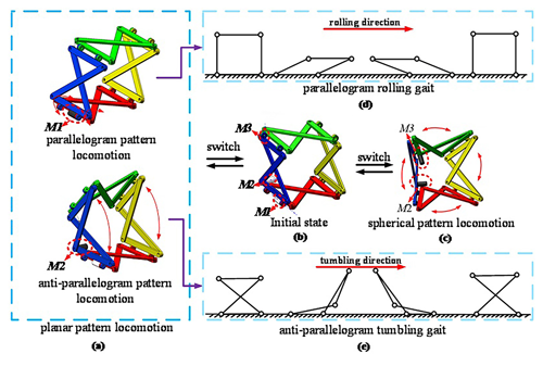
Figure 5The process of the switch between the patterns of locomotion: (a) planar pattern of locomotion, (b) initial state, (c) spherical pattern of locomotion, (d) parallelogram rolling gait, and (e) anti-parallelogram tumbling gait.
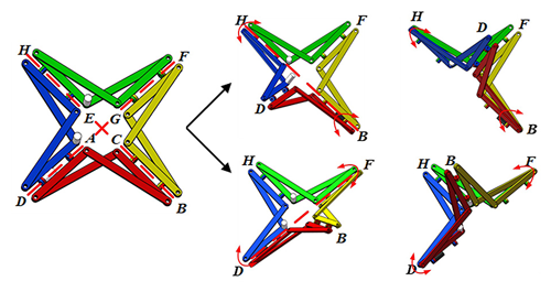
Additionally, with further adjustments to the drive motors M2 and M3, the bars of the mechanism and the revolute joints, RAD, RBC, RGF, and REH, can reach a coplanar state. In this state, the mechanism can be folded and deformed along the axes DF and HB, as illustrated in Fig. 6, and it can be seen that the mechanism can be folded and deformed along the axes DF to form a planar mechanism, DFB(H), where the axes BC and HE overlap, and when folded and deformed along the axis HB, it becomes the plane planar mechanism HBD(F), where the axes AD and FG overlap. In this state, the mechanism can be transformed into the coplanar state, in which the overall envelope size and occupied area of the mechanism are minimized. The mechanism can be further combined with scissor-like mechanisms (Hu et al., 2023), which is conducive to transportation and suitable for scenes with hidden needs.
In this state, the mechanism still has 3 degrees of freedom, but the driving position changes. Specifically, if the drive motor is mounted on the revolute joint RAD, the mechanism will not be able to actively fold and deform along the axis HB.
3.1 Kinematic analysis of patterns of locomotion
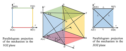
To analyze the movement of the anti-parallelogram ring four-array rolling mechanism in the planar pattern of locomotion, we first abstract it into a geometrical model based on the mechanism's sketch without loss of generality. Then the coordinate system is established on this basis. The original point of the coordinate system is A, with the x axis aligned with AD, the y axis lying in plane ABCD and perpendicular to the x axis, and the z axis determined according to the right-hand rule, as depicted in Fig. 7.
In Fig. 7, the mechanism is in its initial state. It can be observed that point C is located on the y axis, and point E is located on the z axis. In this state, it is easy to prove that the revolute joints, RAD, REH, RFG, and RBC, in the large ring mechanism are parallel to one another.
From Fig. 7, it is evident that the projection of the mechanism onto the y–z plane can be represented as a parallelogram mechanism and the projection onto the x–z plane can be represented as an anti-parallelogram mechanism given the mechanism's initial position. The length of bar AD is denoted as l1, and the length of bar AH is denoted as l2.
The mechanism possesses 3 degrees of freedom in the initial state. θ1 represents the dihedral angle between planes ADHE and ADBC, controlling the deformation movement of the four articulated planes. θ2 is for controlling the deformation movement of a set of anti-parallelogram mechanisms in plane ADHE and plane BCGF, and θ3 is for controlling the deformation movement of a set of anti-parallelogram mechanisms in plane EHFG and plane ADBC.
Since the mechanism is in the initial state, the revolute joints, RAD, REH, RFG, and RBC, are maintained parallel to each other. In other words, the initial angle of θ1 is 90°, and the initial angles of θ2 and θ3 can be deduced from Eq. (1):
3.2 Deformation pattern of the parallelogram rolling gait
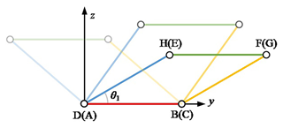
Since the projection of the mechanism onto the y–z plane forms a parallelogram, in the parallelogram rolling gait, θ1 serves as the driving angle, while θ2 and θ3 maintain the initial angle, as illustrated in Fig. 8; with a change in driving angle θ1, the mechanism can show different shapes.
Due to the unique projection angle, points D, B, F, and H are visible, while points A, C, G, and E are obscured. However, each point's position in the mechanism can be obtained based on the corresponding geometric relationships, and the results are provided in the following equations:
Assuming that the weight of the bars is proportional to their length and that the CM of each bar is located at the geometric center of the bar, let the CM point of the mechanism in this state be point N based on the above coordinates. The coordinate of the CM of the mechanism can be calculated as follows:
3.3 Deformation pattern of the anti-parallelogram tumbling gait
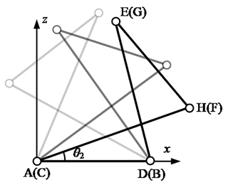
Similarly, the projection of the mechanism onto the x–z plane represents the anti-parallelogram mechanism, where the deformation is driven by angle θ2, and θ1 and θ3 are maintained constant at their initial angles, as depicted in Fig. 9; with a change in driving angle θ2, the mechanism can show different shapes.
Due to the unique projection angle, points A, D, H, and E are visible, while points C, B, F, and G are obscured. However, each point's position in the mechanism can be obtained based on the corresponding geometrical relationships, and the results are provided in the following equations:
Equivalently, assume that the weight of the bars is proportional to their length and that the CM of each bar is located at the geometric center of the bar. Let the center of the mass point of the mechanism in this state be point N. Based on the above coordinates, the CM coordinate of the mechanism can be calculated as follows:
where xE denotes the x axis coordinate of vector rE and zE denotes its z-axis coordinate.
3.4 Kinematic analysis of the spherical pattern of locomotion
The coordinate system of the spherical pattern of locomotion is aligned with the plane state coordinate system, as illustrated in Fig. 10. As is well known, the spherical four-bar mechanism requires the four revolute joints to form a single ring in a series, and the axes of the four revolute joints converge at a point. To briefly prove this, when the revolute joints RAD and RBC are not parallel, the lines AD and BC must intersect at a point in plane ADBC, denoted as point S. The lines AD and EH intersect at a point in plane ADEH, denoted as point S′. Since and AS = AS′, point S coincides with point S′. Using this method, it can be proven that the revolute joints RAD, RBC, and REH converge at point S. Similarly, it can be proven that RAD, RBC, and RFG converge at point S. Therefore, it can be established that point S is the convergence point for the revolute joints, RAD, REH, RFG, and RBC, causing the mechanism to move spherically around point S at this time. When the revolute joints RAD and RBC are parallel, the mechanism enters the planar pattern of locomotion, thus indirectly explaining the essential principle of the two-pattern switching process.
In the spherical pattern of locomotion, the movements maintained by θ2 and θ3 are coupled with each other, which means that θ2=θ3. Both θ2 and θ3 adjust the degree of opening and closing of the mechanism and the position of the center of rotation through their respective angle changes, which can also be understood as the change in the position of point S in the coordinate system. The movement of θ1 and the movement of θ2 and θ3 are independent of each other. θ1 adjusts the angle between faces to realize the mechanism by the sphere of the four bars. Since θ2=θ3, θ2 is used in all analyses in this paper for simplicity.
Firstly, obtaining the vectors of the points on plane ABCD when the mechanism is in the spherical pattern of locomotion is straightforward:
The calculation is made since point S is in plane ADBC, and its vector can be obtained by Eq. (7):
Since plane ADHE and plane ADBC rotate around the x axis, resulting in a dihedral angle of θ1, the vectors of points H and E are obtained using the rotation matrix.
Therefore, vectors rH and rE can be expressed as
Since the four anti-parallelogram mechanisms lie in congruent planes – namely, planes ADBC, ADHE, EHFG, and GFBC are exactly identical – and the mechanism is symmetric about plane SHB, points A and G as well as D and F are symmetric about plane SHB. The space vectors of points G and F can be determined using the symmetry property by utilizing vectors rS, rB, and rH. The equation of plane SHB can be expressed as
Equations (6), (7), and (8) are substituted into Eq. (10) to obtain
where , d2=sin θ2, and d3=cos θ2, Further, plane SHB can be expressed as
where k1=(l2d2)2sin θ1, , and .
Since point A and point G are symmetrical about plane SHB, then vector rAG is parallel to the normal vector of plane SHB. Let rG=[xG yG zG]T. According to Eq. (12), rG can be obtained by
where T is the norm of vector rG. In addition, as , it can be obtained that
Therefore, Eq. (15) is substituted into Eq. (13), and it can be obtained that
Let , , K3=2d1(l2d2)2, and . Equation (16) can be simplified as follows:
In the same way, it can be obtained that
where , , , , and .
Based on the position of each point on the mechanism, the CM position of the mechanism can be obtained as follows:
Let l1=l and . The projection of the zero-moment point (ZMP) in the support region of the mechanism in the static state is shown in Fig. 11 below. At 0° ≤ θ1 ≤ 180°, the projection of the overall CM on the ground is always within its support region, and therefore movement can only be achieved with the aid of dynamic properties.
The ZMP theory is employed to analyze the movement feasibility of the anti-parallelogram ring four-array rolling mechanism. When the ZMP of the mechanism exceeds the support region, the mechanism will be destabilized or even tipped over. For walking robots, it should be ensured that the ZMP of the robot does not exceed the support region of the foot so that the robot can step forward in a stable state. However, for a rolling mechanism, rolling is achieved by making the ZMP exceed the support region of the mechanism, resulting in destabilization. In the following, ZMP theoretical analysis will be used to calculate whether the ZMP of the mechanism can exceed the support region and result in rolling. The ZMP formula is
In the formula, n is the overall number of components of the mechanism; mi is the mass of the ith component; xi, yi, and zi are the coordinates of the center of gravity of the component; , , and are the accelerations of the first component in the direction of the x axis, y axis, and z axis; and g is the acceleration due to gravity. From the above analysis, it can be seen that the mechanism is divided into the planar pattern of locomotion and the spherical pattern of locomotion. The planar pattern of locomotion is subdivided into the parallelogram rolling gait and the anti-parallelogram tumbling gait.
4.1 Planar pattern of locomotion movement feasibility analysis
Firstly, the parallelogram rolling gait in the planar pattern of locomotion is analyzed. When the projection of the mechanism on the y–z plane is a parallelogram, the support region of the mechanism in the y-axis direction is . When ZMP exceeds the support region, the mechanism will turn over. So, the rolling condition of the mechanism is
or
Let the mass of the link with length l1 be m1, the mass of the link with length l2 be m2, and the driving angle . Bringing them into Eq. (23), we obtain
where and .
The effects of the variation in θ1 on yZMP are analyzed when the mechanism is in the initial state, θ1 = 90°. Let l1 = 0.15 m, l2 = 0.21 m, m1 = 0.034 kg, and m2 = 0.048 kg. The yZMP curves of θ1 increasing from 90 to 180° and decreasing from 90 to 0° is shown in Fig. 12.
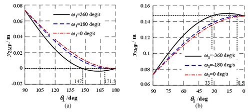
Figure 12The curves of yZMP in parallelogram rolling gait. (a) θ1 increasing from 90 to 180°. (b) θ1 decreasing from 90 to 0°.
In Fig. 12a, θ1 increases from 90 to 180°. When ω = 0, yZMP will not exceed the supporting area. In the case of ω = 180° s−1, yZMP moves out of the supporting area when θ1 ≈ 171.5°. In the case of ω = 360° s−1, yZMP moves out of the supporting area when θ1 ≈ 147.0°. In Fig. 12b, θ1 decreases from 90 to 0°. When ω = 0, yZMP will also not exceed the supporting area. In the case of ω = −180° s−1, yZMP moves out of the supporting area when θ1 ≈ 8.5°. In the case of ω = −360° s−1, yZMP moves out of the supporting area when θ1 ≈ 33.0°.
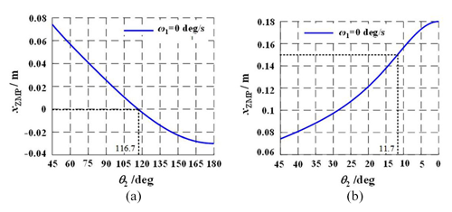
Figure 13The curves of xZMP in anti-parallelogram tumbling gait. (a) θ1 increasing from 45 to 180°. (b) θ1 decreasing from 45 to 0°.
In addition, the anti-parallelogram tumbling gait in the planar pattern of locomotion is analyzed. The projection of the mechanism on the x–z plane is an anti-parallelogram, the mechanism can roll along the x-axis direction in anti-parallelogram tumbling gait, and the supporting area is [0, l1]. The tumbling conditions of the mechanism is
or
Let . The curve of xZMP changing with θ2 can be obtained based on the ZMP theory when the mechanism is in the initial state, θ2 = 45°. When ω = 0, the mechanism can turn over and make a rolling movement. In Fig. 13a, θ2 increases from 45 to 180°, yZMP moves out of the supporting area when θ2 ≈ 116.7°. In Fig. 13b, θ2 decreases from 45 to 0°, and yZMP moves out of the supporting area when θ2 ≈ 11.7°.
It can be found that as increases, the mechanism rolls more easily in the parallelogram rolling gait and the anti-parallelogram tumbling gait.
4.2 Spherical pattern of locomotion movement feasibility analysis
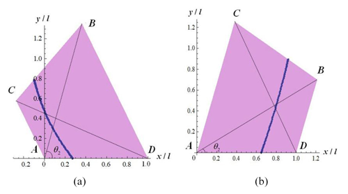
In the spherical pattern of locomotion, the supporting area of the mechanism is an isosceles trapezoid. The area of support can be changed by adjusting θ2 and θ3. The difference from the planar pattern of locomotion is that the feasibility analysis of the spherical pattern of locomotion needs to consider the position relationship between both xZMP and yZMP with the supporting area.

Figure 14The relationship between the ZMP and the supporting area in the spherical rolling gait. (a) θ2=θ3 = 40°. (b) θ2=θ3 = 35°. (c) θ2=θ3 = 30°.
Set the initial value of θ1 to be 90°, and different values of θ2 and θ3 are considered. Figure 14 shows the ZMP projection of the mechanism on the x–y plane and its relationship with the supporting area when θ2=θ3 = 40°, θ2=θ3 = 35°, and θ2=θ3 = 30°, respectively. It can be found that when θ2 and θ3 increase, the mechanism needs a larger ω to realize rolling movement, and the steering angle of the rolling mechanism is larger.
4.3 Obstacle-crossing locomotion movement feasibility analysis
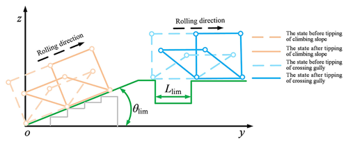
A combination of several simple obstacles with complex obstacles, which can be broadly divided into convex and concave obstacles, was set up. Due to the crawler-type rolling form in this mechanism, convex obstacles, such as vertical obstacles and continuous steps, can be equivalent to a slope. Concave obstacles are mainly gully. Further, we analyze the limit angle of the mechanism to climb the slope. Based on the ZMP analysis of the planar pattern of locomotion, the coordinate system is rotated according to point o, and it is easy to find the limit angle of the mechanism to climb the slope, denoted as θlim (θlim ≈ 48.2°). We classify the slope-climbing state of the mechanism into the state before tipping of climbing slope and the state after tipping of climbing slope. When the slope angle is greater than 48.2°, the mechanism cannot climb up the slope. When the slope angle is smaller than or equal to 48.2°, the mechanism can climb up the slope. Moreover, we analyze the limit width of the mechanism to cross the gully. It is not hard to find that the limit of the mechanism to cross the gully is the length of the mechanism's step, denoted as Llim. We classify the gully-crossing state of the mechanism into the state before the tipping of crossing the gully and the state before the tipping of crossing the gully. When the width of the gully is smaller than the length of the mechanism's step, the mechanism can cross the gully and vice versa, as shown in Fig. 15.
Figure 16a shows the rolling of the robot in the complex terrain, where the surrounding terrain of the robot is divided by environmental awareness. The gray area is the terrain that the robot cannot cross, and the white area is the terrain that the robot can arrive. By dividing the surrounding terrain, the robot can select the optimal route and utilize its existing gaits to complete rolling under the complex terrain. Figure 16b shows the structural outline of the robot under the optimal line. We list four types of obstacles: vertical slope obstacles, stone obstacles, gully obstacles, and sawtooth pavement obstacles. The robot can cross the above obstacle types by its own deformation. It is notable that guaranteeing the mechanism to effectuate precise commutation under diverse gaits in the circumstances of external stochastic interference (Ahmadi et al., 2024) constitutes a crucial problem, and a driver or ancillary device is customarily appended to accomplish the exact commutation of different gaits. The same is true for this paper.

Figure 18The simulation of parallelogram rolling gait:(a) gait 1, (b) gait 2, (c) gait 3, and (d) gait 4.
4.4 Moving strategy
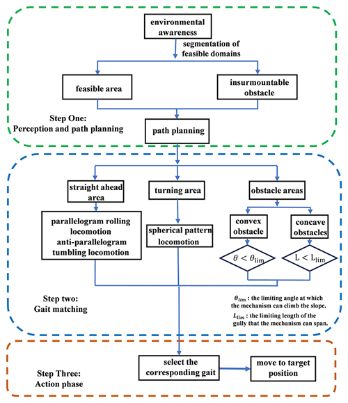
The moving strategy is used to match the terrain with the gait and is divided into three steps. Step one in the moving strategy is perception and path planning, where the sensors carried on the robot perform environment awareness, the surrounding terrain of the robot is divided into the insurmountable obstacles in the surrounding terrain that are marked, and the rest is the feasible area. The robot rolling path is planned inside the feasible area. Step two is gait matching, where we classify the area in the path into a straight-ahead area, turning area, and obstacle area. Different areas are matched with corresponding gaits. Specifically, the straight-ahead area has the parallelogram rolling locomotion and the anti-parallelogram tumbling locomotion. The turning area has the spherical pattern of locomotion. The obstacle area has convex and concave obstacles. The decision condition for whether a convex obstacle can be crossed is if the equivalent slope of convex obstacles is less intense than the limiting angle of the mechanism to climb, and the concave obstacle can be crossed if the width of the concave is smaller than the limit length of the mechanism. In short, the different regions adopt the matching gaits, and the two gaits cooperate with each other to complete the movement. Step three is the action phase, where the robot faces different types of obstacles to choose the corresponding gait, along the planned robot path, moving to the target location, as shown in Fig. 17.
5.1 Rolling gait simulation
The simulation based on anti-parallelogram ring four-array rolling mechanism is carried out to plan the rolling gait based on the feasibility analysis and verify the mechanism's rolling capability. The parameters of the simulation mechanism are given in Table 1.
In the parallelogram rolling gait, M2 and M3 are locked (θ2 = θ3 = 45°), and the mechanism is controlled by M1 (the initial angle of θ1 is 90°). By adjusting the driving angle, the mechanism rolls to the right, as shown in Fig. 18, from the initial state, as θ1 rotates about 81° with ω1 = 180° s−1. The mechanism begins to tumble to the right, and when the ZMP of the mechanism exceeds the support area, the motor stops, and the mechanism flips and travels further forward. Subsequently, the motor is reversed and the drive angle θ1 is flipped to the initial angle at the same speed and the mechanism will return to the initial position. By alternately changing the drive angle, the mechanism can be made to roll continuously in a linear direction.
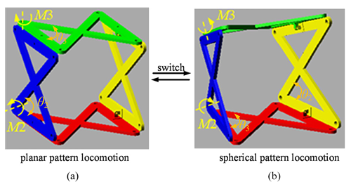
Figure 20The simulation of movement pattern switching. (a) Planar pattern of locomotion. (b) Spherical pattern of locomotion.
In the anti-parallelogram tumbling gait, M1 and M3 are locked (θ1 = 90°, θ3 = 45°), and the mechanism is controlled by M2 (the initial angle of θ2 is 45°). By adjusting the driving angle, the mechanism rolls to the right, as shown in Fig. 19. From the initial state, as θ2 rotates about 35°, the mechanism begins to tumble to the right. Similarly to the parallelogram rolling gait, the mechanism can realize the tumbling movement along a linear movement by alternating the rotation direction of the drive motor.

Figure 21The simulation of spherical rolling gait: (a) gait 1, (b) gait 2, (c) gait 3, and (d) gait 4.
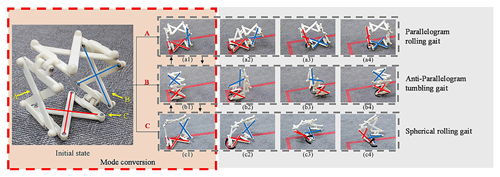
Figure 22Schematic diagram of morphology transition process and relationship. (a1–a4) Parallelogram rolling gait. (b1–b4) Anti-parallelogram tumbling gait. (c1–c4) Spherical rolling gait.
The process of switching between the planar pattern of locomotion and the spherical pattern of locomotion is shown in Fig. 20. The drive motor M1 is locked, and θ1 maintains a 90° angle. M2 and M3 are driven cooperatively to make θ2 and θ3 decrease from 45 to 35° and realize the switching of movement pattern.
In the spherical pattern of locomotion, M2 and M3 are locked (θ2 = θ3 = 35°), and the mechanism is controlled by M1 (the initial angle of θ1 is 90°). By adjusting the driving angle, the mechanism rolls around a point, as shown in Fig. 21. From the initial state, as θ1 rotates about 80° with ω1 = 360° s−1, the mechanism begins to turn over. The steering capability of the mechanism is realized by turning over several times.
5.2 Prototype experiments
The model prototype of the anti-parallelogram ring four-array rolling mechanism is made to verify the switching of the three rolling gaits, which has been described in the introduction part of this paper, and the deformation process in the rolling and the switching between the three rolling gaits are mainly verified here. As shown in Fig. 22, in the initial state, A, B, and C are the three observation directions, Fig. 22a1–a4 show the parallelogram rolling gait. Figure 22b1–b4 show the anti-parallelogram tumbling gait. Figure 22c1–c4 show the spherical rolling gait.
Through the verification of the model prototype, the mechanism can integrate the characteristics of the parallelogram rolling mechanism, the anti-parallelogram tumbling mechanism, and the spherical four-bar rolling mechanism. In the future, specific design and testing can be carried out according to actual application scenarios.
In this paper, an anti-parallelogram ring four-array rolling mechanism is proposed which has planar and spherical patterns of locomotion. The planar pattern of locomotion is subdivided into the parallelogram rolling gait and the anti-parallelogram tumbling gait. The CM of the mechanism is acquired through kinematic analysis, and its movement feasibility is analyzed through ZMP theory. By analyzing the feasibility of the mechanism's obstacle-crossing and moving strategy, the mechanism can complete a seamless switch between the corresponding motion modes under different area. The rolling capability and the capability to switch between spherical and planar patterns of locomotion of the mechanism are verified through simulation analysis and prototype experiments. The mechanism has achieved our expected results, switching flexibly between multiple rolling gaits (parallelogram rolling gait, anti-parallelogram tumbling gait, and spherical rolling gait). When the mechanism is in the coplanar state, the mechanism has a preferable hiding capability. By adjusting the angle of the anti-parallelogram articulated unit in the spherical pattern of locomotion, it has the capability to smoothly adjust the angle in a large range in the direction of movement of the mechanism. In future work, we will be adjusting a portion of its connecting bar profile to reduce the impact of the ground on the mechanism in order to achieve greater rolling efficiency. Larger-scale deformation is one of the highlights of this paper. We will investigate the role of scaling functions in improving the adaptability of mechanism, and through the use of modular components in practical application and in-depth research, the design can be further simplified while retaining its functional advantages. Through the modular design of the mechanical system and control system, it will be possible to simplify the complexity of the mechanism while retaining the functional advantages of the robot, thereby improving its processability and maintainability. Subsequent prototypes will add wear, maintenance, and durability tests and improve the applicability and applicability of the prototype through prototype testing.
All the data used in this article can be made available upon reasonable request. Please contact the first author (xzyxun@126.com).
ZX proposed and developed the general concept of the paper, and performed the mechanism design and analysis. GD, JW, and WZ organized the paper images. WY and CL were responsible for the paper calibration. QG guided the writing of the paper.
The contact author has declared that none of the authors has any competing interests.
Publisher's note: Copernicus Publications remains neutral with regard to jurisdictional claims made in the text, published maps, institutional affiliations, or any other geographical representation in this paper. While Copernicus Publications makes every effort to include appropriate place names, the final responsibility lies with the authors.
This work was supported by the Science and Technology Planning Project of Guangdong (grant nos. 2021B0101420003, 2020ZDZX3013, 2023ZZ03), the Guangdong Basic and Applied Basic Research Foundation (grant no. 2023B1515120064), the Science and Technology Planning Project of Guangzhou (grant no. 202206030007, grant no. 2023ZD001 from the Nansha District, and grant no. 2023GH01 from the Development District), the Guangdong–Macao Advanced Intelligent Computing Joint Laboratory (grant no. 2020B1212030003), and the Opening Project of the Key Laboratory of Safety of Intelligent Robots for State Market Regulation (grant no. GQI-KFKT202205).
This research has been supported by the Science and Technology Planning Project of Guangdong (grant nos. 2021B0101420003, 2020ZDZX3013, 2023ZZ03), the Guangdong Basic and Applied Basic Research Foundation (grant no. 2023B1515120064), the Science and Technology Planning Project of Guangzhou (grant no. 202206030007, grant no. 2023ZD001 from the Nansha District, and grant no. 2023GH01 from the Development District), the Guangdong–Macao Advanced Intelligent Computing Joint Laboratory (grant no. 2020B1212030003), and the Opening Project of the Key Laboratory of Safety of Intelligent Robots for State Market Regulation(grant no. GQI-KFKT202205).
This paper was edited by Zi Bin and reviewed by Mohammad Naeim Moradi and two anonymous referees.
Ahmadi, I., Moradi, M. N., and Panah, M. D.: Dynamic response analysis of nanoparticle-nanobeam impact using nonlocal theory and meshless method, Struct. Eng. Mech., 89, 135–153, https://doi.org/10.12989/sem.2024.89.2.135, 2024.
Amir, H. J. A. and Mojabi, P.: Introducing August: a novel strategy for an omnidirectional spherical rolling robot, IEEE Int. Conf. Robot., 4, 3527–3533, https://doi.org/10.1109/ROBOT.2002.1014256, 2002.
Armour, R. H. and Vincent, J. F. V.: Rolling in nature and robotics: A review, J. Bionic Eng., 3, 195–208, https://doi.org/10.1016/S1672-6529(07)60003-1, 2006.
Biswal, P. and Mohanty P. K.: Development of quadruped walking robots A review, Ain Shams Engineering Journal, 12, 2017–2031, https://doi.org/10.1016/j.asej.2020.11.005, 2021.
Borkar, K. K., Aljrees, T., Pandey, S. K., Kumar, A., Singh, M. K., Sinha, A., Singh, K. U., and Sharma, V.: Stability Analysis and Navigational Techniques of Wheeled Mobile Robot: A Review, Applied Sciences-Robotics and Automation, 11, 3302, https://doi.org/10.3390/pr11123302, 2023.
Chen, B., Huang, K., Pan, H. N., Ren, H., Chen, X., Xiao, J. H., Wu, W. Q., and Lu, H. M.: Geometry-based flipper motion planning for articulated tracked robots traversing rough terrain in real-time, J. Field Robot., 40, 2010–2029, https://doi.org/10.1002/rob.22236, 2023.
Dai, Y., Xiang, F. C., Liu, Z. X., Li, Z. L., Qu, W. Y., and Zhang, Q. H.: Modular Robotic Design and Reconfiguring Path Planning, Appl. Sci., 12, 723, https://doi.org/10.3390/app12020723, 2022.
Ding, L., Hu, L., Liu, Y. Q., Gao, H. B., Deng, Z. Q., Zhang, Y. D., and Tang, C. P.: Design and optimization of a deep-sea multimode crawling–swimming hexapod robot with leg-propeller, Ocean Eng., 280, 114485, https://doi.org/10.1016/j.oceaneng.2023.114485, 2023.
Fei, G. B. and Liu F. G.: Generalized control algorithm and artificial intelligence technology for quadruped walking robot, J. Phys. Conf. Ser., 1982, 012020, https://doi.org/10.1088/1742-6596/1982/1/012020, 2021.
Guan, S. and Liu, X. W.: EEG Signal Radio Frequency Control Wheeled Robot Based on Bi-objective Chaotic Particle Swarm Optimization Algorithm, IOP Conf. Ser.-Mat. Sci., 686, 012008, https://doi.org/10.1088/1757-899X/686/1/012008, 2019.
Haddadin, S., Johannsmeier, L., and Ledezma, F. D.: Tactile Robots as a Central Embodiment of the Tactile Internet, P. IEEE, 107, 471–487, https://doi.org/10.1109/JPROC.2018.2879870, 2019.
Hamlin, G. J. and Sanderson, A. C.: A novel concentric multilink spherical joint with parallel robotics applications, IEEE Int. Conf. Robot., 2, 1267–1272, https://doi.org/10.1109/ROBOT.1994.351313, 1994.
Hoerner, S. and Abbaszadeh, S.: design concept and kinematic model for a soft aquatic robot with complex bio-mimicking motion, J. Bionic Eng., 19, 16–28, https://doi.org/10.1007/s42235-021-00126-4, 2022.
Hu, S. H., Liu, R., Li, R. M., Huang, T. Q., Li, Y. Z., and Yao, Y. A.: Design and analysis of a size-tunable tetrahedron rolling mechanism based on deployable RRR chains, Mech. Mach. Theory, 183, 105284, https://doi.org/10.1016/j.mechmachtheory.2023.105284, 2023.
Lee, W. H. and Sanderson, A. C.: Dynamic rolling linkage and control of modular robots, IEEE T. Robotic. Autom., 18, 32–41, https://doi.org/10.1109/70.988972, 2002.
Lee, W. H., Sanderson, A. C., and York, N.: Dynamic rolling of modular robots, IEEE Int. Conf. Robot., 3, 2840–2846, https://doi.org/10.1109/ROBOT.2000.846458, 2000.
Li, R. M., Yao, Y. A., and Kong, X. W.: Reconfigurable deployable polyhedral mechanism based on extended parallelogram mechanism, Mech. Mach. Theory, 116, 467–480, https://doi.org/10.1016/j.mechmachtheory.2017.06.014, 2017.
Li, Y. W., Ge, S. R., Dai, S. M., Zhao, L. L., Yan, X. C., Zheng, Y. W., and Shi, Y.: Kinematic Modeling of a Combined System of Multiple Mecanum-Wheeled Robots with Velocity Compensation, Multidisciplinary Digital Publishing Institute, 20, 75, https://doi.org/10.3390/s20010075, 2019.
Li, Y. Z., Yao, Y. A., and He, Y. Y.: Design and analysis of a multi-mode mobile robot based on a parallel mechanism with branch variation, Mech. Mach. Theory, 130, 276–300, https://doi.org/10.1016/j.mechmachtheory.2018.07.018, 2018.
Li, Y. Z., Wang, Z. R., Xu, Y. G., Dai, J. S., and Zhao, Z. M.: A deformable tetrahedron rolling mechanism (DTRM) based on URU branch, Mech. Mach. Theory, 153, 104000, https://doi.org/10.1016/j.mechmachtheory.2020.104000, 2020.
Liu, C. H., Li, R. M., Yao, Y. A., Tian, Y. B., Zhang, N., Ji, Y. Y., and Kong, F. Z.: Rolling 4R linkages, Mech. Mach. Theory, 48, 1–14, https://doi.org/10.1016/j.mechmachtheory.2011.10.005, 2012.
Liu, R., Li, R., and Yao, Y. A.: Reconfigurable deployable Bricard-like mechanism with angulated elements, Mech. Mach. Theory, 152, 103917, https://doi.org/10.1016/j.mechmachtheory.2020.103917, 2020.
Lyder, A., Garcia, R. F. M., and Stoy K.: Mechanical design of Odin, an extendable heterogeneous deformable modular robot, 2008 IEEE/RSJ International Conference on Intelligent Robots and Systems, Nice, France, 22–26 September 2008, 883–888, https://doi.org/10.1109/IROS.2008.4650888, 2008.
Ma, X. S., Zhang, K. T., and Dai, J. S.: Novel spherical-planar and Bennett-spherical 6R metamorphic linkages with reconfig urable motion branches, Mech. Mach. Theory, 128, 628–647, https://doi.org/10.1016/j.mechmachtheory.2018.05.001, 2018.
Phipps, C. C. and Minor, M. A.: Introducing the Hex-a-ball, a Hybrid Locomotion Terrain Adaptive Walking and Rolling Robot, Climbing and Walking Robots, 17, 525–532, https://doi.org/10.1007/3-540-26415-9_63, 2006.
Sampada, A., Peter, R., Tejas, R., Raghav, S., Peize, H., and Virvaj R.: Gecko adhesion based sea star crawler robot, Frontiers in Robotics and AI, 10, 273–289, https://doi.org/10.3389/frobt.2023.1209202, 2023.
Sun, X. M., Yu, Z. G., and Zhao, H. F.: Design and Analysis of Reconfigurable Deployable Polyhedral Mechanisms With Straight Elements, J. Mech. Robot., 11, 044502, https://doi.org/10.1115/1.4043601, 2019.
Sun, X. M., Li, R. M., Xun, Z., and Yao, Y. A.: A new Bricard-like mechanism with anti-parallelogram units, Mech. Mach. Theory, 147, 103753, https://doi.org/10.1016/j.mechmachtheory.2019.103753, 2020.
Sun, X. M., Yu, B., and Yu, Z. G.: Construction Method of Loop-Watt Mechanism Based on Watt Six-bars Units, Mech. Mach. Theory, 2587, 012077, https://doi.org/10.1088/1742-6596/2587/1/012077, 2023.
Tagliavini, L., Colucci, G., Botta, A., Cavallone, P., Baglieri, L., and Quaglia, G.: Wheeled Mobile Robots: State of the Art Overview and Kinematic Comparison Among Three Omnidirectional Locomotion Strategies, J. Intell. Robot. Syst., 106, 57, https://doi.org/10.1007/s10846-022-01745-7, 2022.
Teng, X., Li, Y., Liu, Y., and Yao, Y.: Design and Reconfiguration Analysis of the Trunk Mechanism for a Reconfigurable Wheeled Mobile Platform, ASME J. Mechanisms Robotics, 16, 054505, https://doi.org/10.1115/1.4064740, 2024.
Tian, Y. B., Wei, X. Z., Joneja, A., and Yao, Y. A.: Sliding–crawling parallelogram mechanism, Mech. Mach. Theory, 78, 201–228, https://doi.org/10.1016/j.mechmachtheory.2014.03.013, 2014.
Uchida, Y., Saito, T., and Hatakeyama, T.: Development of a multi-purpose module system using Mecanum wheel module, Int. J. Appl. Electrom., 59, 967–975, https://doi.org/10.3233/JAE-171096, 2019.
Ugenti, A., Galati, R., Mantriota, G., and Reina, G.: Analysis of an all-terrain tracked robot with innovative suspension system, Mech. Mach. Theory, 182, 105237, https://doi.org/10.1016/j.mechmachtheory.2023.105237, 2023.
Wang, C. W., Zhang, H., Ma, H. W., Wang, S. S., Xue, X. S., Tian, H. B., and Liu, P.: Simulation and Validation of a Steering Control Strategy for Tracked Robots, Applied Sciences-Robotics and Automation, 13, 11054, https://doi.org/10.3390/app131911054, 2023.
Wu, J., Wang, J. S., Li, T. M., Wang, L. P., and Guan, L. W.: Dynamic dexterity of a planar 2-DOF parallel manipulator in a hybrid machine tool, Robotica, 26, 93–98, https://doi.org/10.1017/S0263574707003621, 2008.
Wu, J., Wang, L., and You, Z.: A new method for optimum design of parallel manipulator based on kinematics and dynamics, Nonlinear Dynam., 61, 717–727, https://doi.org/10.1007/s11071-010-9682-x, 2010.
Wu, J., Li, T. M., and Xu, B. Q.: Force optimization of planar 2-DOF parallel manipulators with actuation redundancy considering deformation, P. I. Mech. Eng. C-J. Mec., 227, 1371–1377, https://doi.org/10.1177/0954406212458055, 2013.
Xian, W. K.: Motion/structure mode analysis and classification of n-RR planar parallelogram mechanisms, Mech. Mach. Theory, 169, 104623, https://doi.org/10.1016/j.mechmachtheory.2021.104623, 2022.
Xun, Z. Y., Guan, Y. H., Xi, L. H., Sun, C. H., and Yao, Y. A.: Three spatial-crossed parallelograms rolling mechanism, J. Mech. Eng., 51, 15–24, 2015.
Xun, Z. Y., Yao, Y. A., Li, Y., Tian, Y. Z., Sun, X. M., Tian, Y. L., and Liu, X. P., A novel rhombohedron rolling mechanism, Mech. Mach. Theory, 105, 285–303, https://doi.org/10.1016/j.mechmachtheory.2016.07.005, 2016.
Yan, C., Shi, K., Zhang, H., and Yao, Y.: Simulation and analysis of a single actuated quadruped robot, Mech. Sci., 13, 137–146, https://doi.org/10.5194/ms-13-137-2022, 2022.
Zhang, N., Shen, L. B., Li, Y. Z., Xun., Z. Y., and Yao, Y. A.: Self-adaptive Deformable Wheel-legged Mobile Mechanism, Mechanical Science and Technology for Aerospace Engineering, 39, 1705–1712, https://doi.org/10.13433/j.cnki.1003-8728.20190320, 2020.
Zhao, Z., Li, Y., Wu, J., and Yao, Y.-A.: Envelop-Climbing Locomotion Planning and Capability Analysis of a Deformable Tetrahedron Rolling Robot, IEEE Robot. Autom. Lett., 8, 4625–4632, https://doi.org/10.1109/LRA.2023.3284374, 2023.
- Abstract
- Introduction
- Mechanism design and degree of freedom analysis
- Kinematic analysis of the mechanism
- Movement feasibility analysis
- Rolling gait simulation and prototype experiments
- Conclusion
- Data availability
- Author contributions
- Competing interests
- Disclaimer
- Acknowledgements
- Financial support
- Review statement
- References


