the Creative Commons Attribution 4.0 License.
the Creative Commons Attribution 4.0 License.
 | 06 May 2025
Design and analysis of a two-stage constant-torque flexure hinge (TS-CTFH) based on fixed-rotation constrained circular-arc segments
Chongxiang Li
Lifang Qiu
Yue Yu
Cuiying Jiang
Shenyuan Dai
This study proposes a pseudo-rigid-body model (4bar-PRBM) for a fixed-rotation constrained circular-arc flexible segment and obtains characteristic parameters expressions using s as a variable. Then, the superposition principle of circular-arc segments is proposed, leading to the development of a novel two-stage constant-torque flexure hinge (TS-CTFH). With the dimension parameter s as a variable, TS-CTFH with different constant-torque output (Tid1 and Tid2) is optimized, which enhances the applicability of the hinge. The accuracy of theoretical analysis and the feasibility of the design scheme are ultimately validated through finite-element analysis (FEA) and testing. The novel TS-CTFH offers a proficient solution for design of grippers, joint rehabilitation devices, and assistive aids for human activities. Simultaneously, the four-bar PRBM offers a user-friendly tool for designing compliant constant-torque mechanisms (CCTMs) with circular-arc segments.
- Article
(1989 KB) - Full-text XML
- BibTeX
- EndNote


Compliant mechanisms (CMs) facilitate the controlled elastic deformation of integrated flexure components to achieve precise force and motion transmission (Howell, 2001). The ability of flexure components to store energy allows for the creation/design of bistable/multistable compliant mechanisms (Howell et al., 2013), compliant constant force/torque mechanisms (Ling et al., 2022), and compliant parallel-guiding mechanisms (Culpepper et al., 2006). In recent years, the study of compliant constant-torque mechanisms (CCTMs) has gained significant attention due to their functional characteristics in rotational motion (Saerens et al., 2022). Within a specified range of operation, CCTMs are capable of delivering nearly constant torques, thereby eliminating the need for complex control structures and excessive sensor usage. The versatility of CCTMs is evident in their widespread application, including rotary positioning stages (Wang et al., 2018), functional joints (Hou and Lan, 2013), and medical robotics (Cheng et al., 2023).
Simultaneously, the mechanical structures and designs of CCTMs exhibit a remarkable diversity. The most commonly used design approach involves optimizing geometric shape parameters of curved beams (Reddy and Zhou, 2017), which necessitates the researcher to provide the initial position and shape function of deformed beams (i.e., to provide the initial value of the optimized variable). (Prakashah and Zhou, 2016). A different approach involves the integration of negative and positive stiffness mechanisms (Zhao et al., 2019; Liu et al., 2020), a commonly employed technique in the design of zero-torque compliant mechanisms (Bilancia et al., 2020). Additionally, precompression of beams can be utilized in the design of CCTMs (Thanaki and Zhou, 2018), effectively reducing the preloading region required for CCTMs (Gandhi and Zhou, 2019). This study enhances the existing pseudo-rigid-body models (PRBMs), offering a robust tool for the design and optimization of a two-stage constant-torque flexure hinge.
Previous research and design efforts have explored circular beam structures. Edwards et al. (2001) introduced a PRBM for initially curved pinned-pinned segments (Edwards et al., 2001). Venkiteswaran and Su (2016) developed a PRBM for circular-arc segments to effectively handle combined force and moment loads (Venkiteswaran and Su, 2016). Building upon this foundation, they proposed a versatile 3R PRBM capable of accurately capturing the behavior of initially curved and straight compliant beams (Venkiteswaran and Su, 2018). Compared to straight beams, the stress distribution of the circular-arc segment in large deformations exhibits greater uniformity (Phan et al., 2024). The design of circular-arc segments offers ease in terms of shape and structural parameters, making them suitable for application in compliant mechanisms (Roach and Howell, 2002). To facilitate the utilization of circular-arc segments in CCTM design, it is imperative to develop a user-friendly tool for their design and analysis.
Primarily, this study presents an innovative contribution through the introduction of an enhanced 4bar-PRBM, wherein the characteristic parameters are proposed using s as a variable in Sects. 2 and 3. Secondarily, a novel design concept for a two-stage constant-torque flexure hinge (TS-CTFH) is proposed. TS-CTFH is optimized with respect to s to achieve various constant-torque output values Tid1 and Tid2 in Sect. 4. Building on this foundation, a prototype of TS-CTFH was developed, exhibiting constant-torque output values of Tid1 and Tid2 at 44.08 and 82.50 N mm, respectively. Finally, finite-element analysis (FEA), theoretical analysis, and testing results are compared to validate the accuracy of 4bar-PRBM and demonstrate the effectiveness of TS-CTFH design in Sect. 5, thereby showcasing the practicality of utilizing 4bar-PRBM for optimizing TS-CTFH.
2.1 Problem formulation
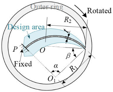
As depicted in Fig. 1, a flexible segment initially shaped as a circular arc exhibits a significant deflection. This kind of constraint of segment can be employed in design of the hinges, where the flexible segment is constrained as follows: one end (P) is fixed, while the other end (Q) moves along a trajectory of a circular arc under constraint of the link (OQ bar). The applied load is represented by the moment (M0) on the OQ bar. To establish a relationship between the moment (M0) and the angle (θ) of the OQ bar, a pseudo-rigid-body model, abbreviated as 4bar-PRBM, for the fixed-rotation constrained circular-arc segment was proposed, as illustrated in Fig. 2.
In Fig. 1, R1 and α denote the radius and central angle of the circular-arc segment PQ. R2 and θ denote the length and rotational angle of the OQ bar. β denotes the position angle of OQ bar, and M0 represents the applied external load. In Fig. 2, KΘ1, KΘ2, γ1, γ2, and γ3 represent the characteristic parameters of 4bar-PRBM, and li (i=1, 2, 3) represents the length of pseudo-rigid bars.
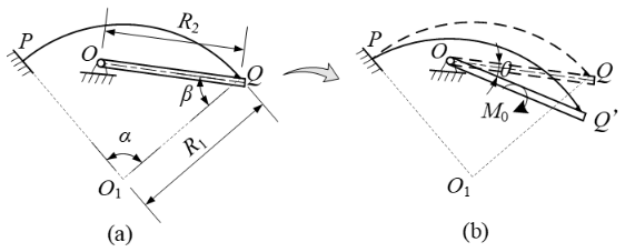
Figure 1Fixed-rotation constrained circular-arc segment (a) prior to applying the load and (b) subsequent to applying the load.
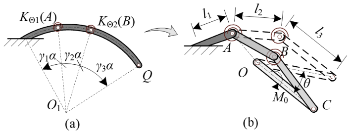
Figure 2PRBM of fixed-rotation constrained circular-arc segment (4bar-PRBM): (a) characteristic parameters and (b) pseudo-rigid bars and pseudo-rigid joints.
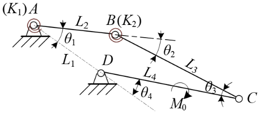
The M0–θ relationship of the fixed-rotation constrained circular-arc segment can be obtained by investigating the 4bar-PRBM and its equivalent four-bar linkage, as indicated in Fig. 3. The 4bar-PRBM uses five characteristic parameters to identify kinematic and torque-angle characteristics of the segment, namely, the stiffness coefficients (KΘ1, KΘ2) and the position factors (γ1, γ2, and γ3).
2.2 Determination of 4bar-PRBM characteristic parameters
The relation between spring stiffness Ki and stiffness coefficient KΘi is as follows:
where
E represents the elastic modulus of material; L denotes the length of circular-arc segment; I stands for the moment of inertia of the cross section; and w and t, respectively, indicate the width and thickness of circular-arc segment.
In Fig. 2, the lengths of each pseudo-rigid bar li, and in Fig. 3, the lengths of each rigid rod Li, are as follows:
The initial values of angles (the values θ10∼θ40 are the initial values of θ1∼θ4) between the rods in Fig. 3 are as follows:
When the CD bar rotates by θ under the influence of M0, the angles between the rods in Fig. 3 are as follows:
The torques generated by the pseudo-hinges A and B are as follows:
Using the principle of virtual work, an expression for the output torque M0 in terms of the included angle θ4 can be obtained as follows:
M0 approximation error e1 is defined as sum of the squared differences between the predicted and actual torques at each loading step. (The angle of each loading step is uniform, and there are altogether N loading steps.)
where M0Pj is the value calculated using Eq. (8) and M0Qj is the FEA values. In FEA, a fixed constraint is imposed at the P end, and rotational displacement is set at the Q end, with the adoption of automatic mesh, program-controlled solver type, and large deflection setting. Then, the torque (M0Qj) data can be obtained in post-processing.
A fitness function can be formulated as a minimization objection function as follows:
Finally, specific values of the characteristic parameters γ1, γ2, γ3, KΘ1, and KΘ2 of the 4bar-PRBM are ultimately determined using MATLAB based on Eq. (10).
3.1 Determination of the constant-torque output region and dimensions of the circular-arc segment
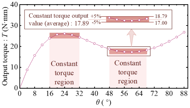
The determination of the constant-torque output region is as follows: if the torque output value does not deviate from the mean by more than 5 % within a certain angular region (usually greater than 10°), the region is set as the constant-torque output region, and the mean torque value in region is the constant-torque output value, as shown in Fig. 4.
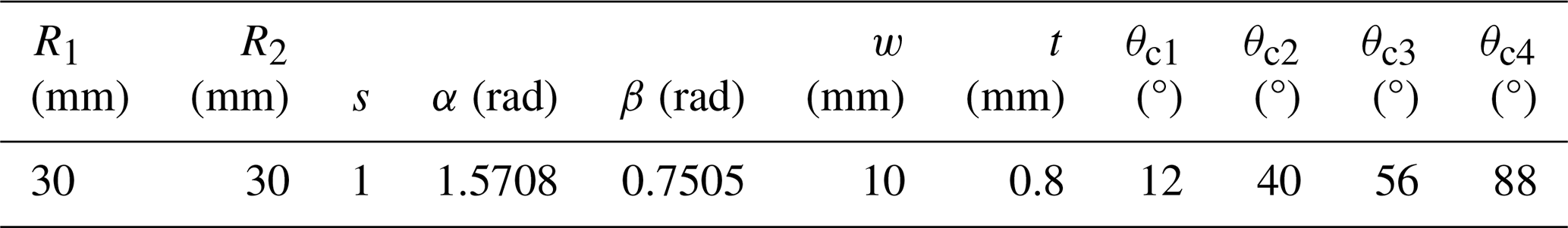
It is necessary to study the relationship between the characteristic parameters (γ1, γ2, γ3, KΘ1, and KΘ2) and dimensions (R1, R2, α, and β). As shown in Fig. 5, the rotational radius R2 determines the size of the hinge, radius and angle (R1 and α) determine the length of the circular-arc segment, and β determines the relative position of the circular-arc segment. Additionally, the width (w) and thickness (t) of the circular-arc beam primarily affect the spring stiffness Ki (as per Eq. 1) and hence the torque output. The initial dimensions of circular-arc segment are given in Table 1. The definition of the ratio s is as follows: here:
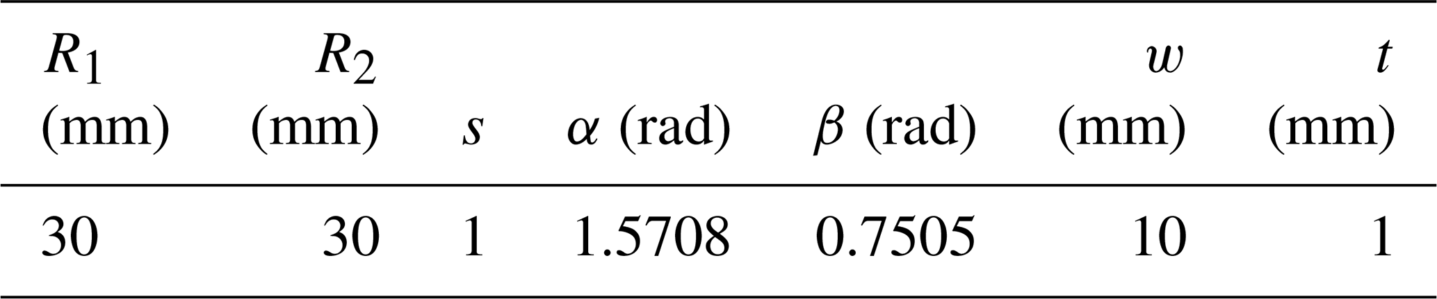
Ratio s determines the magnitude of circular-arc segment relative to the hinge. To achieve desired large deformation, it is recommended that α lies within the range of 1.48 to 1.75, β lies within the range of 0.69 to 0.87, s lies within the range of 0.85 to 1.15.
In FEA, modeling can be conducted based on Fig. 5 and Table 1. A fixed constraint is imposed at the P end, and rotational displacement is set on the outer surface of the outer ring. Then, the torque–angle data of the outer ring can be obtained in post-processing.
In order to improve the accuracy and versatility of the 4bar-PRBM, it is necessary to obtain the characteristic parameter expressions of the 4bar-PRBM under different sizes (s), which enables the 4bar-PRBM to be used for related structural design and serves as a basis for subsequent constant-torque flexure hinge design.
3.2 4bar-PRBM characteristic parameters in terms of the variable s
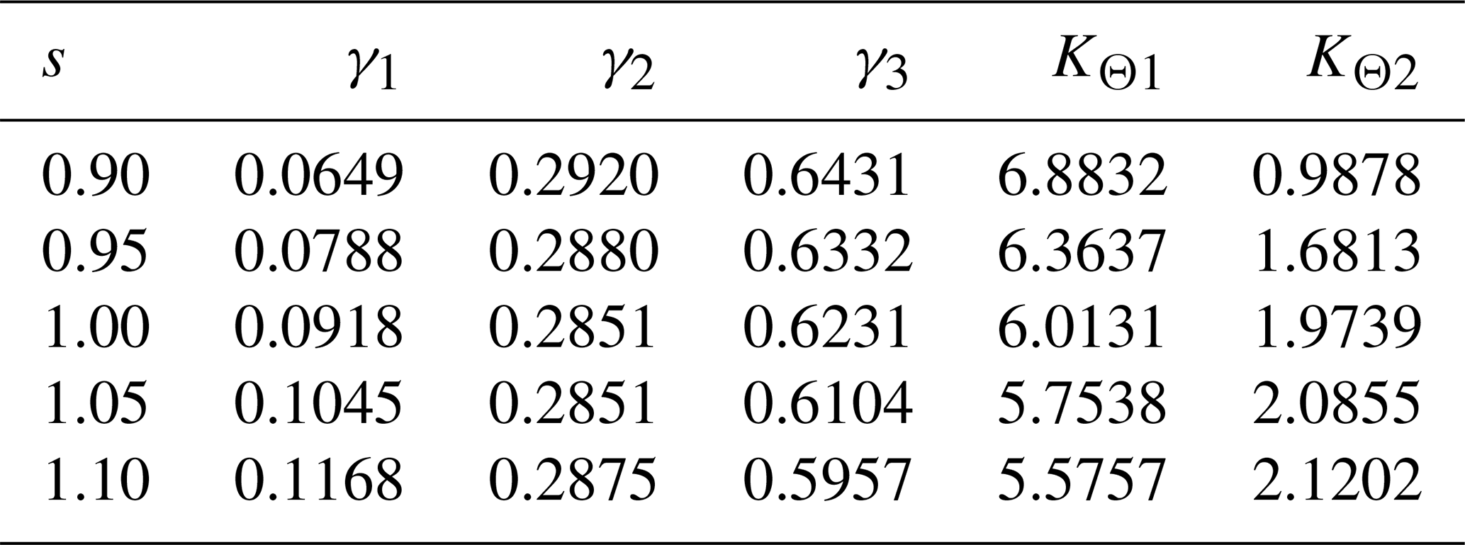
According to Eq. (10), the MATLAB software is employed for the solution with s(R1) as the variable, and the characteristic parameters, as presented in Table 2, can be obtained. Subsequently, under the condition of a goodness of fit greater than 0.95 and the lowest number of polynomial terms, polynomial fitting is conducted. The relationship between the characteristic parameters and the variable s obtained by fitting is as follows:
Table 2Characteristic parameters of corresponding to different svalues.
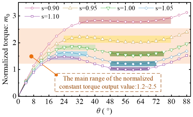
The load torque M0 (derived via FEA and computation) is normalized as , and the m0–θ curve displayed in Fig. 6 is obtained. It is known from Fig. 6 that the ratio s affects the amplitude of the overall curve but has a limited influence on the trend of the curve. Specifically, the constant-torque regions are mostly within 20–40° and 48–76°, and the range of the constant-torque output value (normalized) m0 is approximately from 1.2 to 2.5. Therefore, the constant-torque output value Tid of a single circular-arc segment is selected as follows:
4.1 Superposition principle and mechanical design
Figure 7 illustrates the superposition of two circular-arc segments (Cir-1 and Cir-2), where one segment (Cir-1) initially rotates by θc and then synchronously rotates with the other segment (Cir-2), resulting in a two-stage constant-torque output.
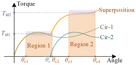
After superposition, the region θc1–θc2 exhibits a constant-torque output of Tid1, while the region θc3–θc4 demonstrates a constant-torque output of Tid2. The curve expression of Ts–θ for the segments after superposition is as follows:
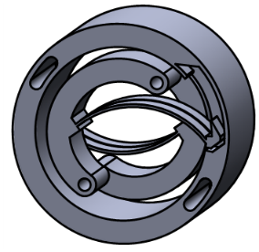
M01 and M02 represent torque outputs of the individual Cir-1 segment and Cir-2 segment, respectively. The number of Cir-1 segments (n1) and Cir-2 segments (n2) determines the circular-arc trajectory of the end of circular-arc segments. To ensure this trajectory, a circular array distribution is required for the Cir-1 segment; thus, n1 should be greater than or equal to 2, as depicted in Fig. 8a. Additionally, as displayed in Fig. 8b, the groove and block are structured in a way that allows both Cir-2 and Cir-1 to turn and deform together after an outer-ring rotation of θc. When , a two-stage constant-torque flexure hinge that is displayed in Fig. 9 is obtained. In this study, the quantities of Cir-1 and Cir-2 are both taken as minimum values (namely, ).
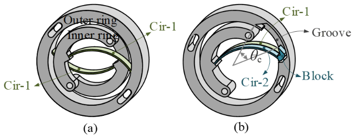
Figure 8Mechanical design of superimposed circular-arc segments: (a) Cir-1 and Cir-1 and (b) Cir-1 and Cir-2.
4.2 Optimization for the two-stage constant-torque output with s as variable
It can be known from Sect. 3.2 that the ratio s has a minor influence on the trend of the m0–θ curve but that it has an impact on the overall amplitude of the curve. Thus, the same dimension parameters can be chosen for Cir-1 and Cir-2, and the desired ratio of constant-torque output can be selected as Tid1 : . The value range of Tid1 can be selected as follows:
The objective function is to minimize the difference between a chosen constant-torque value Tid1 and Tid2 and output torque Ts (θ), which can be expressed as
This equation can be solved using MATLAB.
The material used for TS-CTFH is PA12, Poisson's ratio μ is 0.34, and the bending modulus E is 2.0 GPa. The bending strength of PA12 is capable of reaching 100 MPa. Its dimension parameters are presented in Table 3.
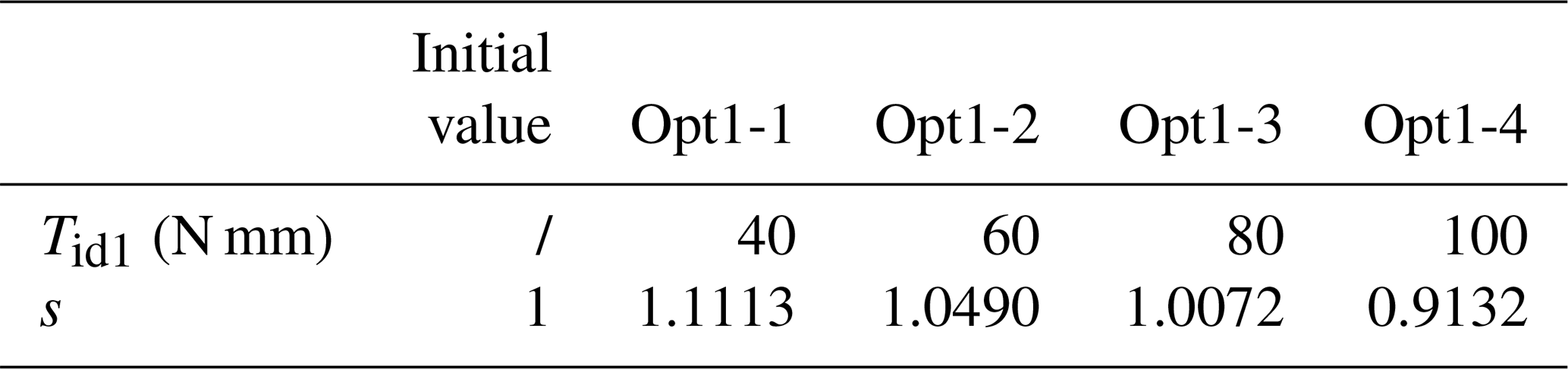
According to the parameters specified in Eq. (15) and Table 3, the range of Tid1 is calculated to be 43.46–90.55 N mm, and the range 40–100 N mm is selected here. Subsequently, for optimization analysis based on Eq. (16), different constant-torque output targets for Tid1 are selected, resulting (Opt1) in the findings presented in Table 4. The value of θc is established at 40°. The values of θc1 and θc2 are determined, based on the constant-torque output regions in the first half of the m0–θ curve in Fig. 6 (primarily concentrated within 16–40°), to be 12 and 40°, respectively. The constant-torque output region in the second half of the curve is supposed to be 40–88°. Considering the 16° loading region, ultimately, θc3 and θc4 are chosen to be 56 and 88°, respectively.
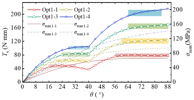
Based on the results of Table 4 and Eqs. (8) and (14), the Ts–θ curve can be derived, as depicted in Fig. 10. The respective constant-torque output regions are indicated thereon. Additionally, the Tid1–Tid2 for Opt1-1 to 1-4 is, respectively, 46.71–78.54 N mm, 63.21–120.82 N mm, 82.82–164.48 N mm, and 102.84-206.08 N mm. The maximum stresses of circular-arc segments are 65.18, 94.17, 118.79, and 141.0 MPa, respectively. Opt1-1 and 1-2 possess a relatively large constant-torque output region and do not exceed the bending strength of the material. Therefore, the two-stage constant-torque output functionality of TS-CTFH has been essentially accomplished.
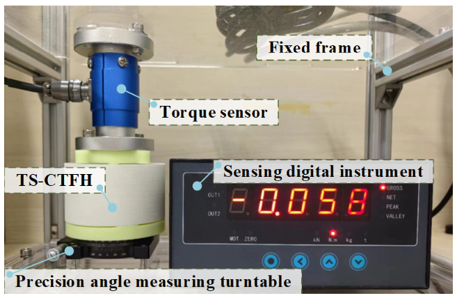
5.1 Prototype and experimental platform
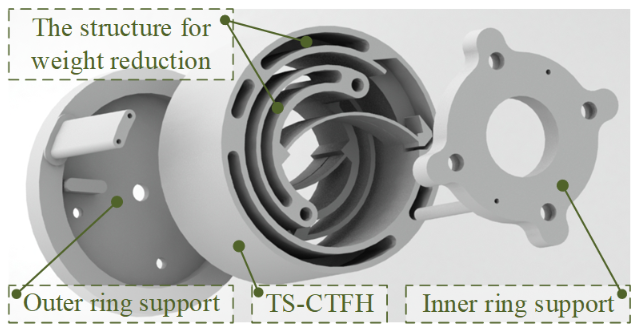
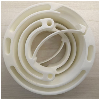
In this section, a confirmatory experiment on Opt1-1 is performed. The TS-CTFH, designed based on parameters optimized by Opt1-1, incorporates weight reduction structures on both the outer and inner rings along with through holes for installing the outer-ring support and inner-ring support as depicted in Fig. 11. Utilizing laser sintering technology, a 3D printed prototype of the TS-CTFH was fabricated, as shown in Fig. 12.
The test platform is depicted in Fig. 13. When outer-ring support rotates at a specific angle, driven by a precision angle measuring turntable, the torque output of inner-ring support can be measured using a torque sensor.
5.2 Experimental results
After Opt1-1 optimization, the circular-arc segments obtained are subjected to FEA analysis, and the Ts–θ curve of TS-CTFH is calculated using the 4bar-PRBM and the principle of superposition. Finally, experimental testing is conducted on the prototype. The results obtained from Opt1-1, including the theoretical, FEA, and test results, are presented in Fig. 14. Error 1 represents the discrepancy between the theory and FEA, with an average error of 2.00 % and a maximum error of 3.90 %. Error 2 indicates the deviation between the test and FEA, with an average error of 3.20 % and a maximum error of 6.93 %. Error 3 is the difference between FEA and theoretical values of the maximum stress in Cir-1, with a maximum error of 3.67 %.
In the experiment, a value was measured every 8°, and the average of three measurements was taken. Experimental results indicate that the constant-torque output regions are 16–40° and 56–88° (which have been marked in Fig. 14). Subsequently, the average torque output within the regions of 16–40° and 56–88° was computed, thereby obtaining the constant-torque output values Tid1 and Tid2 (namely 44.08 and 82.50 N mm). The experimental results demonstrate that the TS-CTFH possesses a two-stage constant-torque output function. These findings validate the accuracy of the 4bar-PRBM and affirm the effectiveness of the optimization strategy.
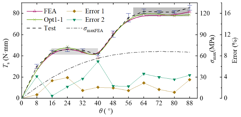
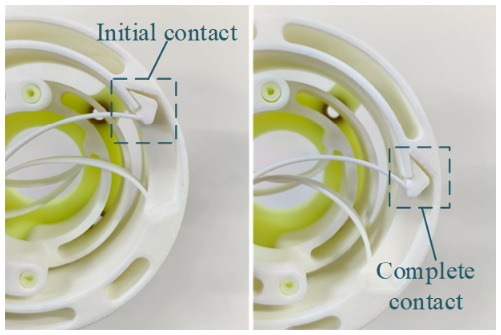
Furthermore, when the rotation angle was 40°, a notable deviation emerged in experimental results. Its primary cause lies in the fact that roughness of prototype surface led to premature contact between the block and the groove. However, this contact was not firm (with an existing gap), as depicted in Fig. 15. When the rotation angle increased, the gap narrowed, and contact became more stable, thereby reducing the errors.
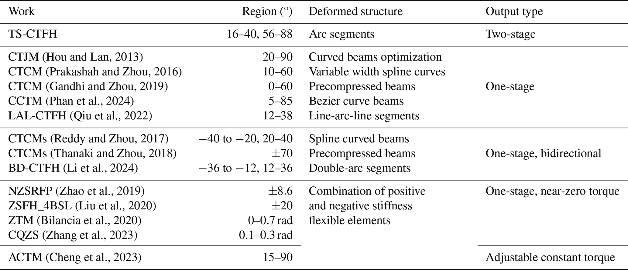
6.1 Comparison of TS-CTFH and other compliant constant-torque mechanisms
TS-CTFH exhibits the characteristics of a two-stage constant-torque output, thereby enhancing the functionality of CTFH and presenting a novel approach to its design. Table 5 presents a comparison between TS-CTFH and existing CCTMs in terms of their constant-torque regions, deformation structure, and torque output type.
Some CCTMs are characterized by large strokes, enabling their application in specific functional joints. CCTMs with zero-torque output characteristics have demonstrated applicability in shock absorption systems and bearing replacement applications, as identified by Bilancia et al. (2020) Furthermore, adjustable constant force/torque mechanisms can be applied well in the medical field.
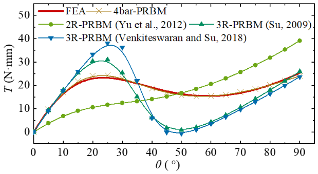
The 2R PRBM (Yu et al., 2012) and 3R PRBM (Su, 2009) were proposed, as depicted in Fig. 16a and b, to capture the deformation and end-point trajectory of a flexible cantilever beam subjected to free-end force and moment loading. Furthermore, a 3R PRBM (Venkiteswaran and Su, 2018) specifically designed for initially curved beams was introduced. The T–θ curves of CTFH obtained by directly utilizing these PRBM parameters are illustrated in Fig. 17. It is evident that the existing PRBMs exhibit significant inaccuracies and fail to accurately fit the T–θ characteristics of the constrained flexible beam shown in Fig. 1. Therefore, the four-bar PRBM proposed in this study introduces an innovative approach for the design of CCTMs with circular-arc segments while serving as a user-friendly tool for their implementation.
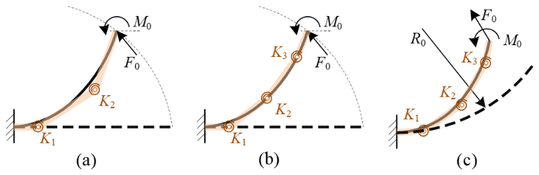
Figure 16Existing PRBMs in references: (a) 2R PRBM (Yu et al., 2012), (b) 3R PRBM (Su, 2009), and (c) 3R PRBM (Venkiteswaran and Su, 2018).
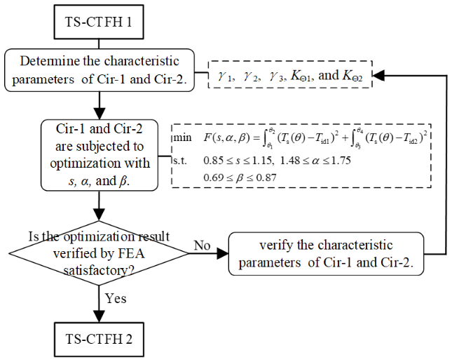
6.2 The further optimization of TS-CTFH
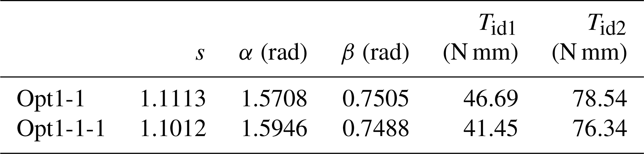
When contemplating the further optimization of Opt1-1, dimension parameters (s, α, and β) can be concurrently regarded as design variables. The optimization procedure is depicted in Fig. 18. Based on Opt1-1, identical dimension parameters are selected for Cir-1 and Cir-2, and dimension parameters (s, α, and β) are regarded as design variables to optimize the output torques Tid1 and Tid2. The expression is
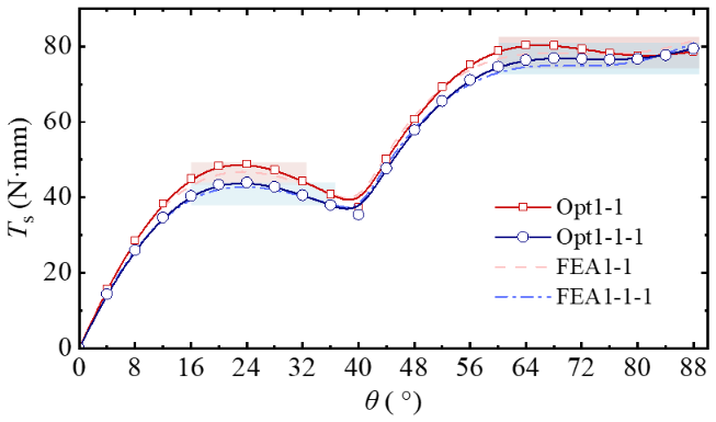
The ultimate optimization outcome (Opt1-1-1) is presented in Table 6. By conducting the simulation of the optimized circular-arc segments, the result shown in Fig. 19 is obtained. It can be concluded that the simulation results of Tid1 and Tid2 for Opt1-1-1 are 40.92 and 76.35 N mm, respectively. Moreover, the torque output of the first stage of Opt1-1-1 is smoother, attaining a more desirable two-stage constant-torque output effect.
Primarily, this study introduces the 4bar-PRBM for a fixed-rotation constrained circular-arc segment and provides the corresponding characteristic parameters for different s values. Based on this, expressions of the characteristic parameters are derived using the ratio s as a variable.
Secondarily, the superposition principle is employed to design circular-arc segments, resulting in the development of a two-stage constant-torque flexure hinge (TS-CTFH). Based on the optimized parameters of Opt1-1, a prototype of TS-CTFH was fabricated using 3D printing technology.
Finally, an experimental test is conducted to compare the FEA, theoretical analysis, and testing results. The maximum error between theory and FEA is determined to be 3.90 %, while the maximum error between the test and FEA is found to be 6.93 %. These findings validate the accuracy of the 4bar-PRBM model and confirm the effectiveness of optimization outcomes. The constant-torque output regions of the TS-CTFH prototype are identified as 16–40° and 56–88°, with the torque values Tid1 and Tid2 determined to be 44.08 and 82.50 N mm, respectively, thereby achieving the functionality of a two-stage constant-torque output.
All the data used in this paper can be obtained upon request from the corresponding author.
CL developed the method and wrote the majority of the paper. LQ conceived the idea. YY focused on the optimal design of CTFH. CJ and SD assisted with the simulation and the experiment. All the authors read and approved the final paper.
The contact author has declared that none of the authors has any competing interests.
Publisher's note: Copernicus Publications remains neutral with regard to jurisdictional claims made in the text, published maps, institutional affiliations, or any other geographical representation in this paper. While Copernicus Publications makes every effort to include appropriate place names, the final responsibility lies with the authors.
The authors are grateful for the support provided by National Natural Science Foundation of China (grant no. 51475037) and Scientific and Technological Innovation Foundation of Foshan (grant no. BK22BF008).
This research has been supported by the National Natural Science Foundation of China (grant no. 51475037) and Scientific and Technological Innovation Foundation of Foshan (grant no. BK22BF008).
This paper was edited by Haiyang Li and reviewed by three anonymous referees.
Bilancia, P., Smith, S. P., Berselli, G., Magleby, S. P., and Howell, L. L.: Zero torque compliant mechanisms employing pre-buckled beams, J. Mech. Des., 142, 1–4, https://doi.org/10.1115/1.4046810, 2020.
Cheng, Z., Savarimuthu, T. R., Foong, S., and Tan, U. X.: Design of Adjustable Constant Force/Torque Mechanisms for Medical Applications, J. Mech. Robot., 15, 1–10, https://doi.org/10.1115/1.4054638, 2023.
Culpepper, M. L., DiBiasio, C. M., Panas, R. M., Magleby, S., and Howell, L. L.: Simulation of a carbon nanotube-based compliant parallel-guiding mechanism: A nanomechanical building block, Appl. Phys. Lett., 89, 11–14, https://doi.org/10.1063/1.2388143, 2006.
Edwards, B. T., Jensen, B. D., and Howell, L. L.: A pseudo-rigid-body model for initially-curved pinned-pinned segments used in compliant mechanisms, J. Mech. Des. Trans. ASME, 123, 464–472, https://doi.org/10.1115/1.1376396, 2001.
Gandhi, I. and Zhou, H.: Synthesizing constant torque compliant mechanisms using precompressed beams, J. Mech. Des., 141, 1–7, https://doi.org/10.1115/1.4041330, 2019.
Howell, L. L.: Compliant Mechanisms, Wiley-Interscience, 480 pp., ISBN 047138478X, 2001.
Howell, L. L., Magleby, S. P., and Olsen, B. M.: Handbook of Compliant Mechanisms, Wiley, 352 pp., ISBN 1119953456, 2013.
Hou, C. W. and Lan, C. C.: Functional joint mechanisms with constant-torque outputs, Mech. Mach. Theory, 62, 166–181, https://doi.org/10.1016/j.mechmachtheory.2012.12.002, 2013.
Li, C., Qiu, L., Dai, S., and Jiang, C.: Research on a double-arc constant-torque flexure hinge with bidirectional output, Precis. Eng., 89, 381–392, https://doi.org/10.1016/j.precisioneng.2024.07.004, 2024.
Ling, J., Ye, T., Feng, Z., Zhu, Y., Li, Y., and Xiao, X.: A survey on synthesis of compliant constant force/torque mechanisms, Mech. Mach. Theory, 176, 104970, https://doi.org/10.1016/j.mechmachtheory.2022.104970, 2022.
Liu, T., Bi, S., Yao, Y., Dong, Z., Yang, Q., and Liu, L.: Research on zero-stiffness flexure hinge (ZSFH) based on spring four-bar linkage(4BSL), Mech. Mach. Theory, 143, 103633, https://doi.org/10.1016/j.mechmachtheory.2019.103633, 2020.
Phan, T. V., Truong, V. M., Pham, H. T., and Nguyen, V. K.: Design of a Novel Large-Stroke Compliant Constant-Torque Mechanism Based on Chained Beam-Constraint Model, J. Mech. Robot., 16, 1–10, https://doi.org/10.1115/1.4063980, 2024.
Prakashah, H. N. and Zhou, H.: Synthesis of constant torque compliant mechanisms, J. Mech. Robot., 8, 1–8, https://doi.org/10.1115/1.4034885, 2016.
Qiu, L., Li, C., Dai, S., and Yu, Y.: Research on the line-arc-line constant-torque flexure hinge (LAL-CTFH) based on improved pseudo-rigid-body model (PRBM), Mech. Mach. Theory, 174, 104878, https://doi.org/10.1016/j.mechmachtheory.2022.104878, 2022.
Reddy, B. P. and Zhou, H.: IMECE2017-70333, 1–10, 2017.
Roach, G. M. and Howell, L. L.: Evaluation and comparison of alternative compliant overrunning clutch designs, J. Mech. Des., 124, 485–491, https://doi.org/10.1115/1.1480414, 2002.
Saerens, E., Furnémont, R., Legrand, J., Langlois, K., García, P. L., Crispel, S., Rossini, M., Verstraten, T., Vanderborght, B., and Lefeber, D.: Constant Torque Mechanisms: A Survey, Appl. Mech. Rev., 74, 1–18, https://doi.org/10.1115/1.4054565, 2022.
Su, H. J.: A pseudorigid-body 3r model for determining large deflection of cantilever beams subject to tip loads, J. Mech. Robot., 1, 1–9, https://doi.org/10.1115/1.3046148, 2009.
Thanaki, M. and Zhou, H.: Synthesizing bidirectional constant torque compliant mechanisms using precompressed beams, ASME Int. Mech. Eng. Congr. Expo. Proc., 4A-2018, 1–9, https://doi.org/10.1115/IMECE2018-86469, 2018.
Venkiteswaran, V. K. and Su, H. J.: Pseudo-rigid-body models for circular beams under combined tip loads, Mech. Mach. Theory, 106, 80–93, https://doi.org/10.1016/j.mechmachtheory.2016.08.011, 2016.
Venkiteswaran, V. K. and Su, H. J.: A Versatile 3R Pseudo-Rigid-Body Model for Initially Curved and Straight Compliant Beams of Uniform Cross section, J. Mech. Des., 140, 1–8, https://doi.org/10.1115/1.4040628, 2018.
Wang, P., Yang, S., and Xu, Q.: Design and Optimization of a New Compliant Rotary Positioning Stage with Constant Output Torque, Int. J. Precis. Eng. Manuf., 19, 1843–1850, https://doi.org/10.1007/s12541-018-0213-x, 2018.
Yu, Y. Q., Feng, Z. L., and Xu, Q. P.: A pseudo-rigid-body 2R model of flexural beam in compliant mechanisms, Mech. Mach. Theory, 55, 18–33, https://doi.org/10.1016/j.mechmachtheory.2012.04.005, 2012.
Zhang, C., He, J., Zhou, G., Wang, K., Xu, D., and Zhou, J.: Compliant quasi-zero-stiffness isolator for low-frequency torsional vibration isolation, Mech. Mach. Theory, 181, 105213, https://doi.org/10.1016/j.mechmachtheory.2022.105213, 2023.
Zhao, H., Zhao, C., Ren, S., and Bi, S.: Analysis and evaluation of a near-zero stiffness rotational flexural pivot, Mech. Mach. Theory, 135, 115–129, https://doi.org/10.1016/j.mechmachtheory.2019.02.003, 2019.
- Abstract
- Introduction
- 4bar-PRBM of a fixed-rotation constrained circular-arc segment
- Expressions of the characteristic parameters of 4bar-PRBM with respect to dimension parameters
- Design of a two-stage constant-torque flexure hinge (TS-CTFH)
- Experimental testing
- Discussion
- Conclusions
- Data availability
- Author contributions
- Competing interests
- Disclaimer
- Acknowledgements
- Financial support
- Review statement
- References