the Creative Commons Attribution 4.0 License.
the Creative Commons Attribution 4.0 License.
 | 09 Apr 2025
Investigation of cutting performance of coated micro-textured tools for cutting aluminum alloys
Tiantian Xu
Lintao Xie
Chunlu Ma
Qinghua Li
Due to the high thermal conductivity and large thermal expansion coefficient of aluminum alloy materials, significant cutting forces are easily generated during metal processing, which affects the quality of the finished product. In this paper, by deeply exploring the mechanism of micro-textures on tool surfaces, we designed and prepared three types of micro-textured tools with identical morphologies but differing distributions. Cutting tests were conducted to analyze the specific impact of micro-textures on the rake and flank faces of the tool on cutting performance. To further optimize the cutting efficiency of these micro-textured tools, a coating treatment was applied to their surfaces, and an in-depth study was conducted on the changes in cutting performance under the synergistic effect of micro-textures and coating materials. The research results indicate that tools with micro-textures on both the rake and the flank faces exhibit optimal cutting performance. Furthermore, such tools with coated micro-textures can further reduce cutting forces by 21.57 % and cutting temperatures by 7.56 %, effectively facilitating the smooth discharge of chips and preventing the accumulation of cutting heat on the tool surface. This paper explores the interaction between micro-textures and coating materials, as well as their specific impacts on cutting performance, providing a theoretical foundation for subsequent research on coated micro-textured tools.
- Article
(9444 KB) - Full-text XML
- BibTeX
- EndNote


In recent years, with the continuous development of tribology, relevant research scholars have proposed a concept of surface micro-texturing (Wang et al., 2022; Sharma et al., 2021; Sundar et al., 2023). Surface micro-texturing refers to the machining of tiny, geometrically arranged shapes according to certain rules on the surface of the friction subsurface to improve the surface properties by changing the physical structure of the material surface (Su et al., 2023; Wang et al., 2020). With the development of microfabrication, surface micro-texturing has been successfully combined with mechanical components such as bearings, gears, engine cylinders, and guide rails and has been proven to be an effective means to improve tribological properties.
Yang et al. (2020) processed micro-textures with different densities on the surface of mold steel and conducted comparative tests on smooth samples. It was found that the fluctuation value of the coefficient of friction of the micro-texture was much larger than that of the smooth specimen during the wear-in stage and that the coefficient of friction was lower than that of the surface friction of the smooth condition after the wear-in stage, and it was also found that the surface wear of the specimen decreased with the increase in the density of the micro-texture on the surface. Hao et al. (2020) fabricated the micro-texture with different dimensions on the inner surface of hybrid ceramic bearings and compared the stability of the micro-texture bearings with three kinds of micro-texture bearings and conventional bearings for three different area ratios and conventional bearings in terms of stability. The test results show that the micro-texture has little effect on the amplitude of the bearing rotor system at low speeds, and with the increase in rotational speed, the micro-texture bearing promotes the reduction in amplitude of 22.6 % compared with the conventional bearing system. It can be seen that the reasonable surface micro-texture can significantly improve the friction coefficient of the friction vice and optimize the use performance.
At present, the most commonly used methods for the preparation of surface micro-texturing include laser processing, electric discharge machining (EDM), photolithography, and ultrasonic processing, among which laser processing is the most widely used (Škamat et al., 2021; Lin and Hong, 2021; Wu et al., 2020). With the continuous development of tribology and micromachining technology, relevant studies have shown that high-performance surface textiles can realize good friction reduction and anti-wear and antibonding functions, which provides a new research direction for the study of friction reduction and anti-wear on tool surfaces. Sun et al. (2021) investigated the effect of micro-texturing on tool wear resistance during the cutting of titanium alloys and found that parallel-fluted micro-textured tools can reduce the coefficient of friction by 14 %. Compared with conventional tools, the surface wear rate of parallel-groove micro-textured tools was reduced by 35 %–70 % and the surface roughness was improved by 29 %. Wang et al. (2021) prepared micro-textures on the surface of diamond tools using a laser, investigated their friction and cutting properties, and found that the cutting force and friction coefficients of the micro-textured diamond tools were reduced, except for the concentric micro-textures. Meanwhile, the cutting performance of single crystal diamond tools was effectively improved. Fouathiya et al. (2021) in order to prevent the adhesion of titanium alloy chips to the tool during the cutting process, prepared micro-textured tools with different geometries and sizes on the surface of the tool and carried out practical cutting tests; it was found that the cross-shaped micro-textured tools significantly contributed to the reduction in the cutting force, the coefficient of friction, and the phenomenon of tool wear. Yu et al. (2020) for the composite micro-textured in the lubricated condition, the simulation test results showed that the bionic micro-textured tool was superior to the conventional tool in both dry and wet lubrication conditions, and the machining efficiency was found to be significantly improved in the lubricated condition. In addition, a new lubrication method, i.e., a small amount of lubrication, is proposed, which has the best lubrication effect and greatly reduces the use of cutting fluid. The above studies have shown that micro-texturing on specific positions on the tool surface can improve the friction state between the tool and chip contact surface during the cutting process and optimize the cutting performance of the tool.
However, with the concept of green manufacturing, the use of cutting fluid is often avoided when cutting. Under dry cutting conditions, the tool surface is exposed to high temperature and pressure for a long time, and the surface friction is intense, which is easy to cause wear. Although the micro-textured tool can improve the surface friction state during cutting, cutting without lubricating oil can easily cause tool wear (Szczotkarz et al., 2021; Salur et al., 2021; Şirin et al., 2021). Based on this relevant research, scholars have proposed a new method of combining the two friction reduction methods of tool surface coating and microfabrication; firstly, microfabrication is prepared on the surface of the tool, and then coating is carried out on the basis of micro-textured tools to optimize the cutting performance of the tool using the synergistic effect of the microfabrication and the coating material properties (Tang et al., 2021; Duan et al., 2022; Xin et al., 2022; Guo et al., 2023). Guo et al. (2023) used finite-element simulation to simulate the machining performance of three kinds of micro-textured tools for machining high-temperature alloys under two different material conditions and found that the addition of coating materials on the surface of the tools can effectively improve the machining efficiency and also that different shapes of the micro-textured tools produce different degrees of secondary cutting during the cutting process. Wu et al. (2022) took the TiAlN-coated carbide tools as a research object and explored the influence of laser parameters (laser energy, scanning speed, and number of scans) on the groove morphology of TiAlN-coated tools and the bonding state between the coating and the substrate. It was found that when the laser energy was 10 µJ, the scanning speed was 0.7 mm s−1, the number of scans was five, the groove micro-textured morphology was the most ideal, and the surface wear of the inserts with the groove micro-textured morphology was reduced by 25 % compared with that of the conventional tools. Based on the above research on coated micro-textured tools, it is found that the high hardness and heat resistance of the coating material can protect the surface texture of the tool, which can further improve the friction and wear resistance of the micro-textured tool and prolong the tool life.
Through the above research, it can be seen that previous research often focuses on optimizing the cutting performance of the tool by preparing the micro-texture on the surface of the front face of the tool, and less research focuses on the back face of the tool; the coating material on the surface of the tool is relatively simple, and the effect of the composite coating material on the cutting performance of the tool is not considered. This paper, through the actual cutting aluminum alloy test, found that the cutting easily causes chip curl winding, cutting force and rough surface of the workpiece after machining, and other test phenomena. Therefore, the micro-textured structure was prepared on both the front and back surfaces of the tool, and the coating treatment was carried out on the tool to investigate the effects of micro-textured structure distribution and coating material on the cutting performance.
2.1 Test materials and equipment
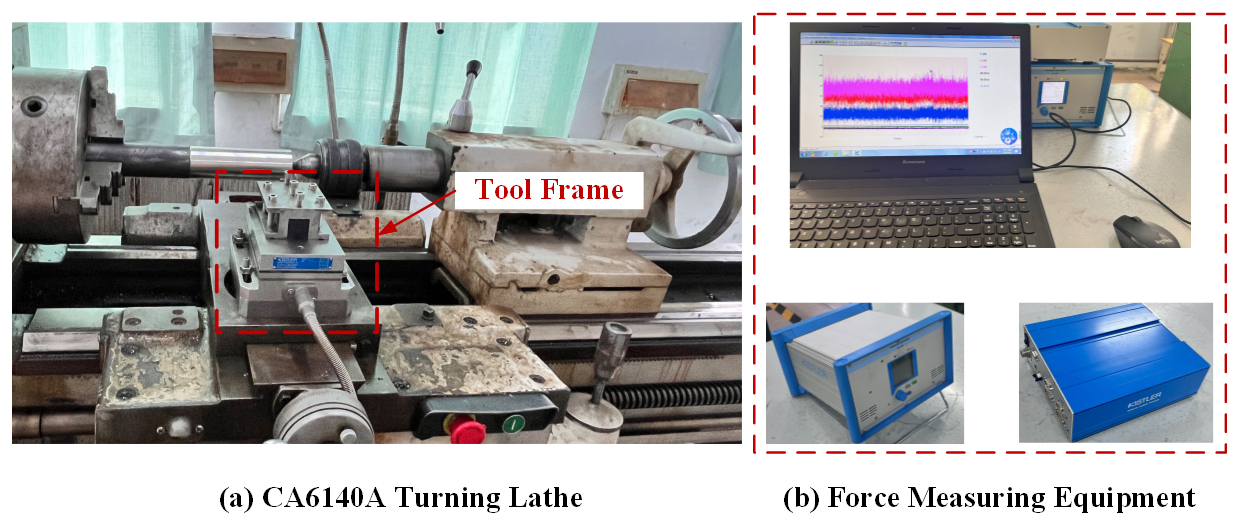
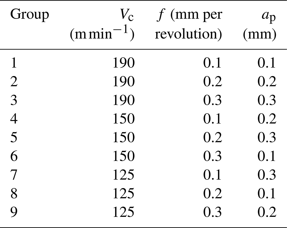
In order to investigate the effect of the cutting amount on the cutting performance of cemented carbide materials, the cutting test of dry cutting aluminum alloy bar stock was carried out using the test equipment shown in Fig. 1, and the cutting amount is shown in Table 1. The tool used for the test is a carbide tool, and the workpiece is a round bar of aluminum alloy with a diameter of 50 mm and a length of 200 mm, with the surface of the bar pretreated and the top holes machined at both ends.
During the aluminum alloy cutting test, a Kistler 9527B force gauge was installed at the bottom of the tool holder to measure the three-way cutting force, and data on the interaction force generated between the tool and the workpiece during the cutting process were collected. After the cutting process was completed, the surface roughness of the machined aluminum alloy workpiece was measured several times using a three-dimensional profilometer. The collected data were analyzed to study the effect of the cutting dosage on the cutting force and surface roughness.
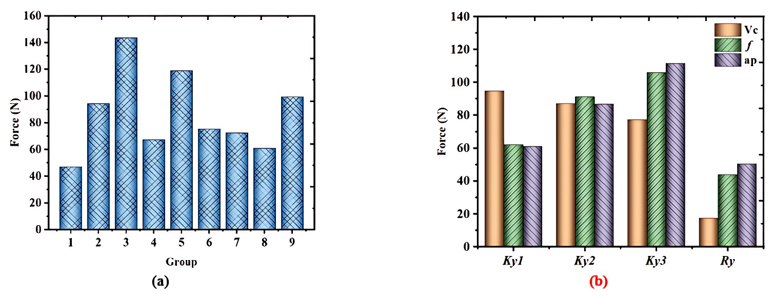
Figure 2Effect of cutting parameters on cutting forces: (a) effect of cutting parameters on cutting forces and (b) cutting force analysis of the cutting force range analysis.
2.2 Analysis of experimental results
2.2.1 Effect of cutting parameters on the cutting force
Cutting force is an important factor affecting the machining accuracy in the cutting process and is the general term for the force between the tool and the workpiece in the cutting process. The size of the cutting force affects the quality, efficiency, and tool life of the cutting process. Therefore, the cutting force generated during the cutting of aluminum alloy is collected, and the influence of cutting parameters on the cutting force is plotted as shown in Fig. 2. From the graph, it can be seen that when the cutting dosage such as the one in test group 1 is used, the cutting force is the smallest; when the cutting quantity is as in group 3, the cutting force is the largest.
In order to obtain the effect of cutting amount on the cutting force, the data in Fig. 1a are analyzed by polar analysis, and the cutting force polar analysis graph is plotted as shown in Fig. 1b, where Kyi denotes the average value of the cutting force at the ith level and Ry denotes the polar deviation. From Fig. 1b, it can be seen that the depth of cut, feed, and cutting speed affect the cutting force in descending order. It is also found that the cutting force generated increase with the increase in the cutting amount. This is due to the fact that as the cutting amount increases; the material removal rate per unit time increases; the material deformation of the cutting layer of the workpiece intensifies; the number of chips produced at the same time increases; and the vibration of the machine tool during machining intensifies, leading to an increase in the cutting force.
2.2.2 Effect of cutting parameters on surface roughness
After the cutting aluminum alloy test, the machined bar is placed on the test bench, and the surface quality of the workpiece is measured using a three-dimensional profiler; the surface morphology of the machined workpiece is shown in Fig. 3, and the observation of the surface morphology of the workpiece reveals that the widths of the cutter marks on the surface of the workpiece after machining with different cutting dosages are not the same. When the spindle speed is high, the cutting marks formed are more compact and smooth; the marks formed by a higher feed are wider, and the marks formed by a higher depth of cut are deeper. Observation of Fig. 3 reveals that there are different degrees of damage on the surface of the workpiece after machining is completed. Figure 3a has burrs generated on the surface of the workpiece, and Fig. 3b has obvious red heat on the surface of the workpiece, which is due to the fact that during the cutting process, the chips accumulate on the surface of the tool, and the cutting heat generated during the cutting accumulates on the surface of the tool, which results in the adhesion of the chips and affects machine accuracy.
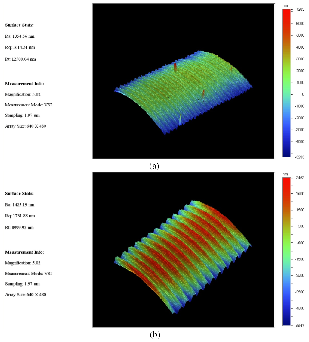
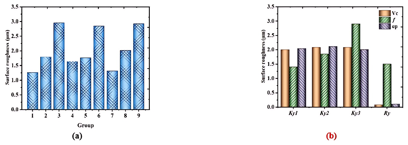
Figure 4Effect of cutting parameters on surface roughness: (a) effect of cutting parameters on surface roughness and (b) surface roughness polarization analysis.
To further analyze the impact of the nine sets of cutting parameters in Table 1 on the surface roughness of the machined workpiece, the surface roughness of each processed group was statistically recorded. The surface roughness data of the workpieces are presented in Fig. 4a. Additionally, a range analysis of these data was conducted, as shown in Fig. 4b. From the figure, it can be seen that as the surface roughness fluctuates significantly with the change in cutting dosage, in which the surface roughness is the smallest when the cutting parameters is as in test group 1 and the surface roughness is the largest when the cutting amount is as in test group 3. It was also found that the influence on the surface roughness from the largest to the smallest is the feed, depth of cut, and cutting speed. This is due to the fact that with the increase in cutting speed, the lathe drives the workpiece to rotate rapidly, and the vibration generated by high-speed rotation leads to an increase in the roughness of the machined surface, while too high a rotational speed is prone to causing the temperature of the machining area to rise, leading to plastic deformation of the cutting layer of the workpiece material and the chip curling phenomenon. In order to avoid this situation, we should choose the appropriate cutting dosage and avoid the use of excessive cutting speed so as to ensure the surface quality of the machined surface and machining stability.
From the above analysis of the effect of the cutting amount on cutting force and surface roughness, it can be seen that when the cutting amount is selected unreasonably, it leads to the decline of machining accuracy. Therefore, the selection of tool material and cutting parameters is crucial for improving the cutting efficiency and machining quality of aluminum alloy materials.
3.1 Analysis of the mechanism of friction reduction and anti-wear effect of micro-textures
In the metal cutting process, the friction between the tool surface chip and the resistance to the elastic–plastic deformation of the machined material is the main source of cutting force (Yang et al., 2017). For cutting, the friction between the tool and the chip is mainly concentrated on the front face of the tool, and the friction directly affects the shape of the chip, tool wear, and surface quality of the workpiece after machining. In the microscopic state, the contact between the two objects can be regarded as point–peak contact, in the cutting process, which means that the contact area between the tool and the workpiece is subjected to the role of the load applied by the machine tool, resulting in an increase in the number of points of contact in the contact area, the contact area increases. The applied external load is usually concentrated in the point peak, the point peak is subjected to stress to reach the yield limit value of the material, and the material produces plastic deformations. Therefore, the actual contact area between the tool and the workpiece can be expressed as follows:
where FN is the load on the contact surface and σs is the extruded yield limit of the contact material.
The friction generated during cutting can be expressed as follows:
where τs is the shear strength.
Therefore, the friction coefficient in the point–peak contact region is
Substituting Eq. (3) into Eq. (1) yields
From Eq. (4), it can be seen that the friction coefficient in the point–peak contact area between the tool and the workpiece can be determined by the ratio of the shear strength to the extruded yield limit of the material, from which it can be seen that the modified friction coefficient is a constant. From Eq. (1), it can be seen that in the area of close contact on the tool surface, there is also an increase in the external load and the actual contact area. When the actual contact area increases to the theoretical contact area A1, that is, A=A1, then even if the external load continues to increase, the actual contact area is always equal to the theoretical contact area. At this time, the friction force can be expressed as follows:
The coefficient of friction can be expressed as follows:
It can be seen from Eq. (6) that the friction coefficient of the contact area decreases with the decrease in the contact area when the external load is a constant value. Therefore, the theory of friction reduction and antifriction of the micro-textured tool is proposed by preparing micro-texture in the close contact area of the front face of the tool to improve the actual contact area between the tool and the chip to change the friction state of the tool surface and then reduce the cutting force, and the micro-textured tool action mechanism diagram is shown in Fig. 5.
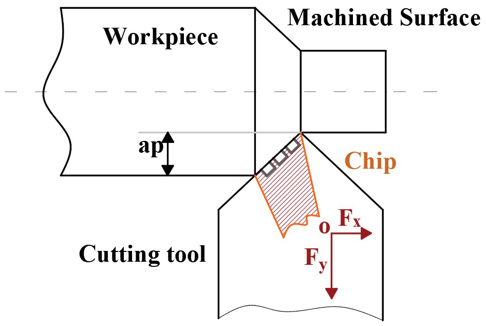
Figure 6 shows the theoretical analysis of the cutting force of the cutting tool model, and the direction of chip outflow is the same as the direction of the tool eating resistance Ft during cutting. Therefore, Ft is decomposed into axial force Fx and radial force Fy, while the main cutting force Fz remains unchanged. Therefore, the three-way cutting force equation can be obtained as follows: the main cutting force Fz, axial force Fx and radial force Fy (Orra and Choudhury, 2018; Rosas et al., 2022) are
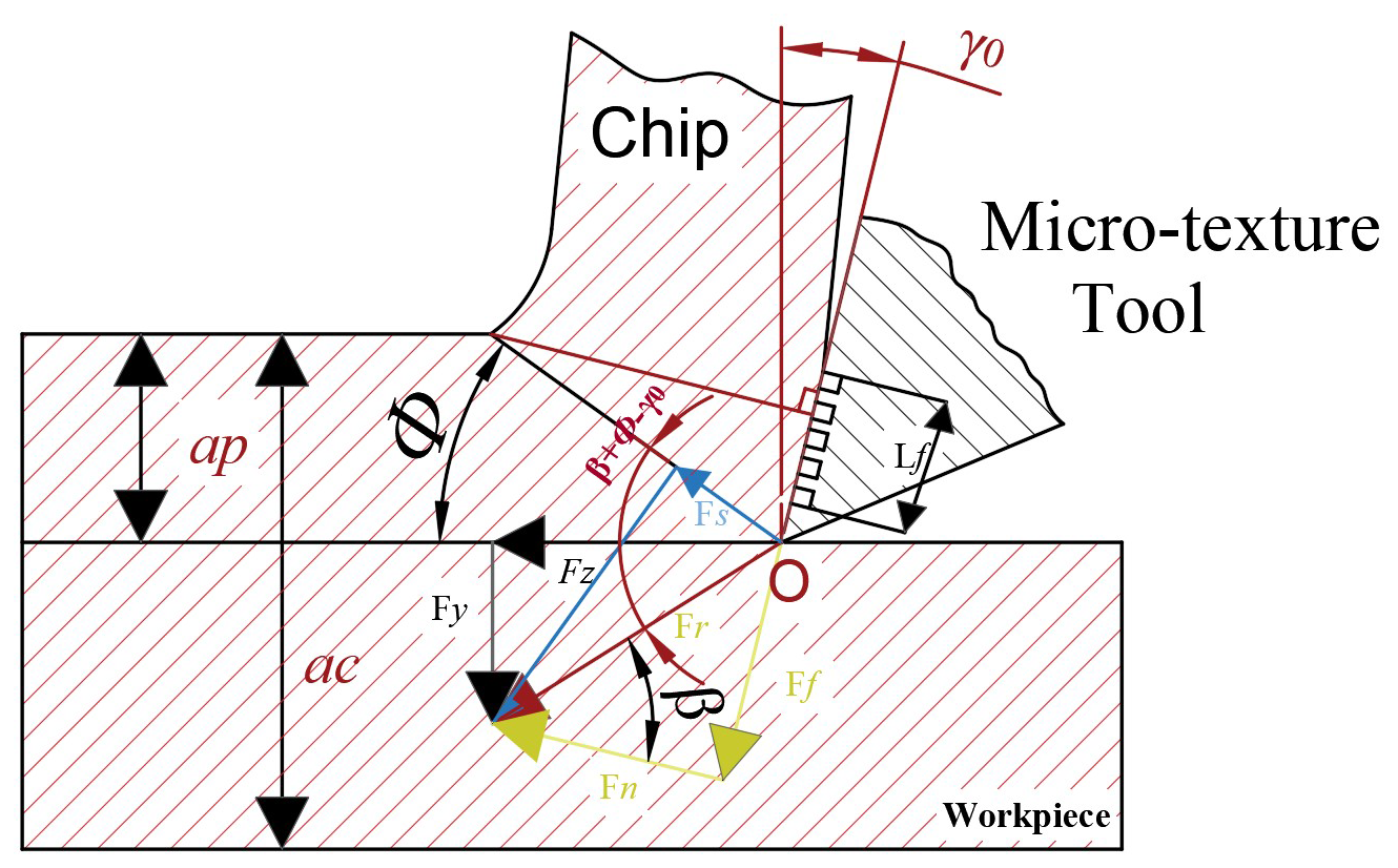
where is the actual contact length of the tool chip, Lf is the theoretical contact length of the tool chip, l0 is the width of the micro-texture, and n is the number of micro-textured in the contact area of the tool chip. In Eq. (6), ac is the width of the cut, ψr is the residual deflection angle, β is the friction angle, γ0 is the leading angle of the tool, and ψλ is the outflow angle of the chip. As shown in Eq. (9), the existence of tool surface structure makes the actual contact length of the tool chip smaller than the theoretical contact length of the tool chip. As shown in Eqs. (7)–(9), there is a positive correlation between the three-directional cutting force and the theoretical contact length of the tool and chip in the micro-textured tool.
3.2 Analysis of the mechanism of action of coating materials
In order to optimize the performance of the tool in dry cutting conditions to obtain high-quality parts and components, the relevant researchers and scholars investigated the coating treatment on the tool surface so that the tool surface is coated with refractory-metal or non-metallic compounds with high hardness, high abrasion resistance, and other properties of the better hard-coating materials; the micro-textured coating tool preparation process is shown in Fig. 7.
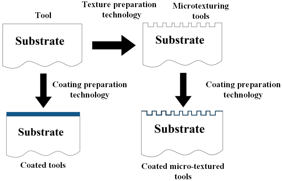
The coating material acts as a chemical and thermal barrier, avoiding direct contact between the tool and the chip; reducing the friction and interaction between the tool and the workpiece; and enhancing the tool's oxidation resistance, adhesion resistance, and abrasive wear resistance, thus prolonging the tool's service life (Tong Xin et al., 2022; Duan et al., 2022; Wang et al., 2024). Surface weaving technology prepares different types of micro-textures on the tool surface, which can improve the tribological behavior of the tool chip contact surface and the contact surface. Therefore, in this paper, surface micro-texturing technology and coating technology are combined to prepare coated micro-textured tools to further optimize tool performance.
Cutting tool machining is a complex process. In recent years, thanks to the rapid development of high-performance computers and finite simulation, finite-element simulation technology in the field of cutting has been widely used for the study of cutting performance of the tool to provide a theoretical basis for the study of cutting performance.
4.1 Three-dimensional modeling
Three kinds of micro-textured tool models and traditional tool models with the same shape but different positions were designed by three-dimensional modeling software, respectively: a front-facing grooved micro-textured tool, named the Q tool; a back-facing grooved micro-textured tool, named the H tool; and a front-and-back-facing grooved micro-textured tool, named the QH tool; as well as the traditional tool, named the T tool, as shown in Fig. 8. The specific parameters of the micro-textures are as follows: the width of the micro-texture is 50 µm, depth of the micro-texture is 50 µm, minimum edge distance of the micro-texture (distance from the main cutting edge) is 200 µm, and spacing of the micro-texture is 200 µm.
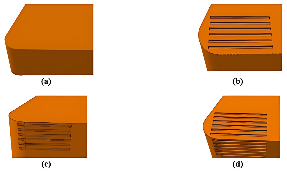
Figure 8A three-dimensional model of the tool; (a) T tool, (b) Q micro-texturing tool, (c) H micro-texturing tool, and (d) QH micro-texturing tool.
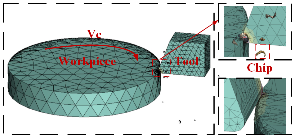
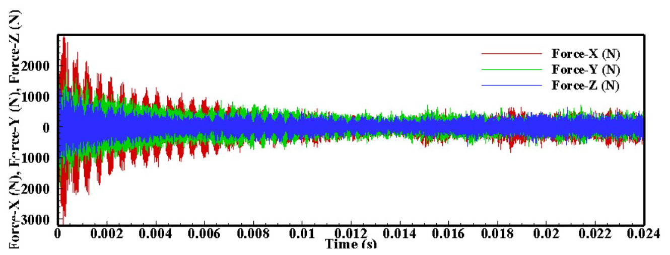
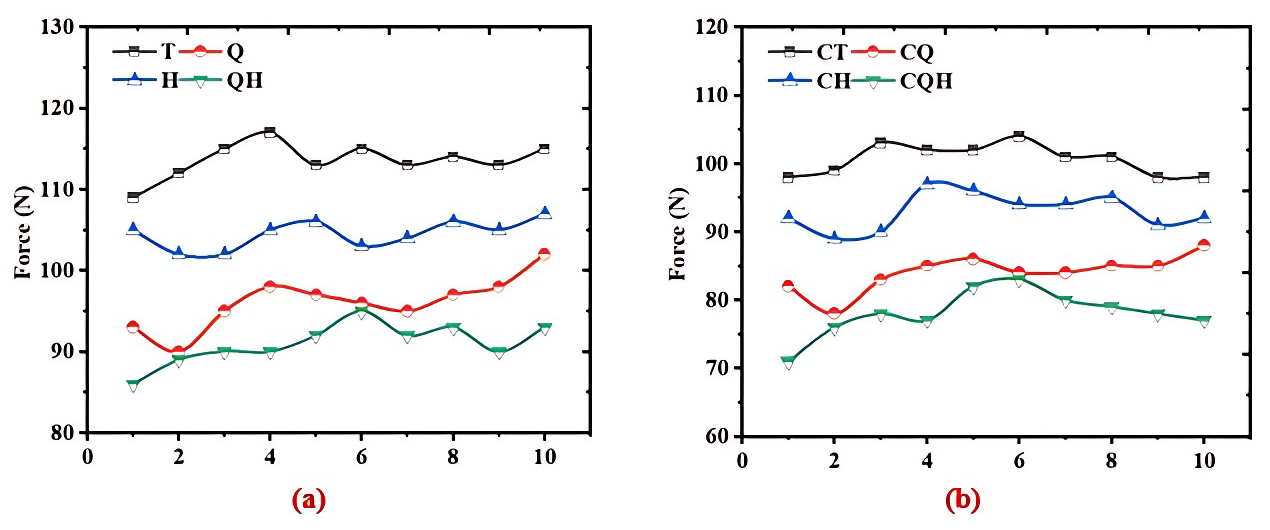
Figure 11Comparison of cutting forces between coated micro-textured and micro-textured tools; (a) cutting forces of micro-textured tools and (b) cutting forces of coated micro-textured tools.
With dry cutting being more and more widely used, the mechanical properties of the tool requirements are higher, and with the application of alloys, stainless steel, titanium alloys, composites, and other difficult-to-process materials, the hardness, toughness, resistance to high-temperature oxidation, thermal stability, and other properties of the tool material put forward higher requirements. The application of tool coating makes the tool obtain good cutting performance, so this paper on the micro-textured tool surface and traditional tool surface coating treatment aims to explore the micro-textured and coated material synergistic effect on the cutting performance of the tool.
The TiAlN material is formed by adding Al to the TiN material layer for wear resistance. When cutting at high temperature, the Al element oxidizes to generate dense Al2O3, which plays the role of antioxidation and anti-diffusion wear as well as heat insulation. Therefore, TiAlN coating has high hardness, wear resistance, and resistance to high-temperature oxidation, suitable for machining titanium alloy, aluminum alloy, and other difficult-to-process materials. Therefore, in this paper, a 5 µm layer of TiAlN material coated on the surface of the tool is selected for the study. The four types of tools after coating are named as follows: coated conventional tool is the CT tool, coated front-facing grooved micro-textured tool is the CQ tool, coated back-facing grooved micro-textured tool is the CH tool, and coated front-and-back-facing grooved micro-textured tool is the CQH tool.
4.2 Coated micro-textured cutting tool aluminum alloy tests
In the cutting simulation experiment, the tool material is set to be cemented carbide, the workpiece material is aluminum alloy, and the cutting dosage used in the test is the cutting speed of 150 m min−1, feed of 0.2 mm per revolution, and depth of cut of 0.3 mm. During the cutting process, the initial ambient temperature is set to 20 °C. The cutting speed is set to 0.1 mm per revolution, and the cutting depth is 0.1 mm. In the simulation process, mesh is an important concept, which refers to the three-dimensional space divided into many small cubes, each of which contains a certain amount of matter and information. The significance of this is to discretize a complex object or system into small pieces, allowing us to calculate and analyze it numerically. Therefore, the maximum mesh size of the tool away from the cutting region is set to 0.1 mm, and the refinement size of the micro-textured part is set to 0.01 mm; the maximum size of the workpiece away from the cutting-layer part is set to 3 mm, and the mesh of the cutting layer on the surface is refined. The finite-element simulation meshing of the tool and workpiece is shown in Fig. 9.
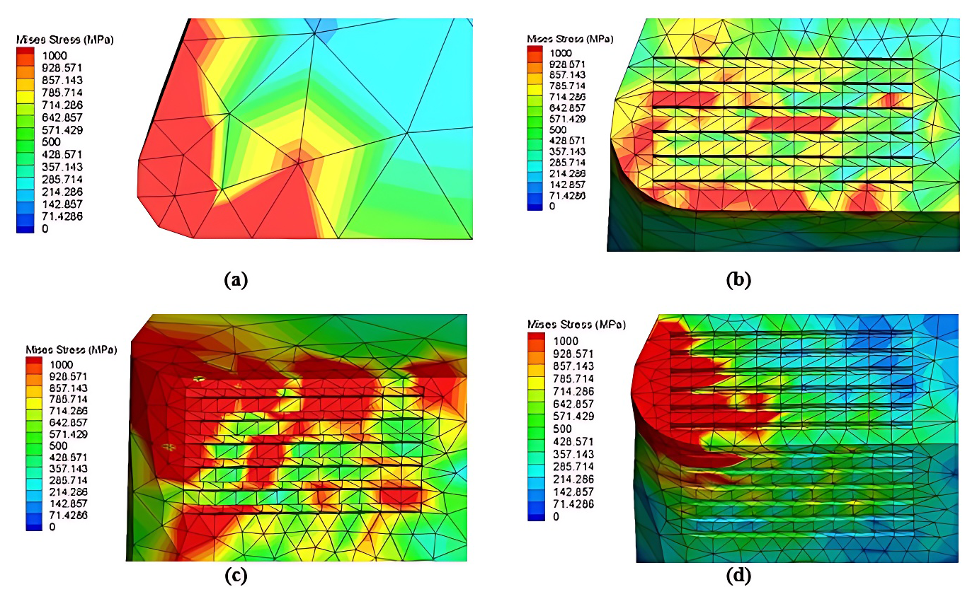
Figure 12Stress distribution on tool surface: (a) T tool surface stress, (b) Q tool surface stress, (c) H tool surface stress, and (d) QH tool surface stress.
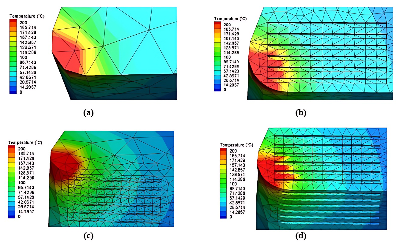
Figure 13Surface temperature distribution of conventional and micro-textured tools: (a) T tool surface temperature, (b) Q tool surface temperature, (c) H tool surface temperature, and (d) QH tool surface temperature.
4.3 Simulation test results and analysis
4.3.1 Influence of lubrication condition on cutting force
After the cutting simulation test is completed, the results of the simulation are processed using the postprocessing module of the finite-element simulation software to generate the cutting force fluctuation diagram of the micro-texturing cutting tool aluminum alloy, as shown in Fig. 10. Observing the cutting force fluctuation diagram, it can be seen that when the cutting starts, the tip of the tool starts to touch the workpiece slowly, the tip part and the cutting layer of the material are extruded, and the cutting force rises sharply. As the cutting proceeds, it enters the smooth cutting stage, and the cutting force stabilizes year by year. Due to the discrete nature of the data, cutting simulation of cutting force fluctuations affecting the processing and analysis of data, with the help of simulation software data fitting function, these discrete data are fitted to a smooth curve and easy to observe, and data extraction is performed; in order to improve the accuracy of the cutting stabilization stage to select 10 points as the cutting force data points, the cutting force data of these data points are recorded for analysis. During the cutting simulation experiment, the cutting parameters were set to a cutting speed of 150 m min−1, a feed rate of 0.2 mm per revolution, and a cutting depth of 0.3 mm. The resulting cutting force from the simulation was 113° N, while the actual cutting force measured in the physical cutting test was 118.88° N. A comparative analysis of these results indicates that the error between the simulation and the actual test falls within an acceptable range, demonstrating that this cutting simulation holds significant practical relevance and application value.
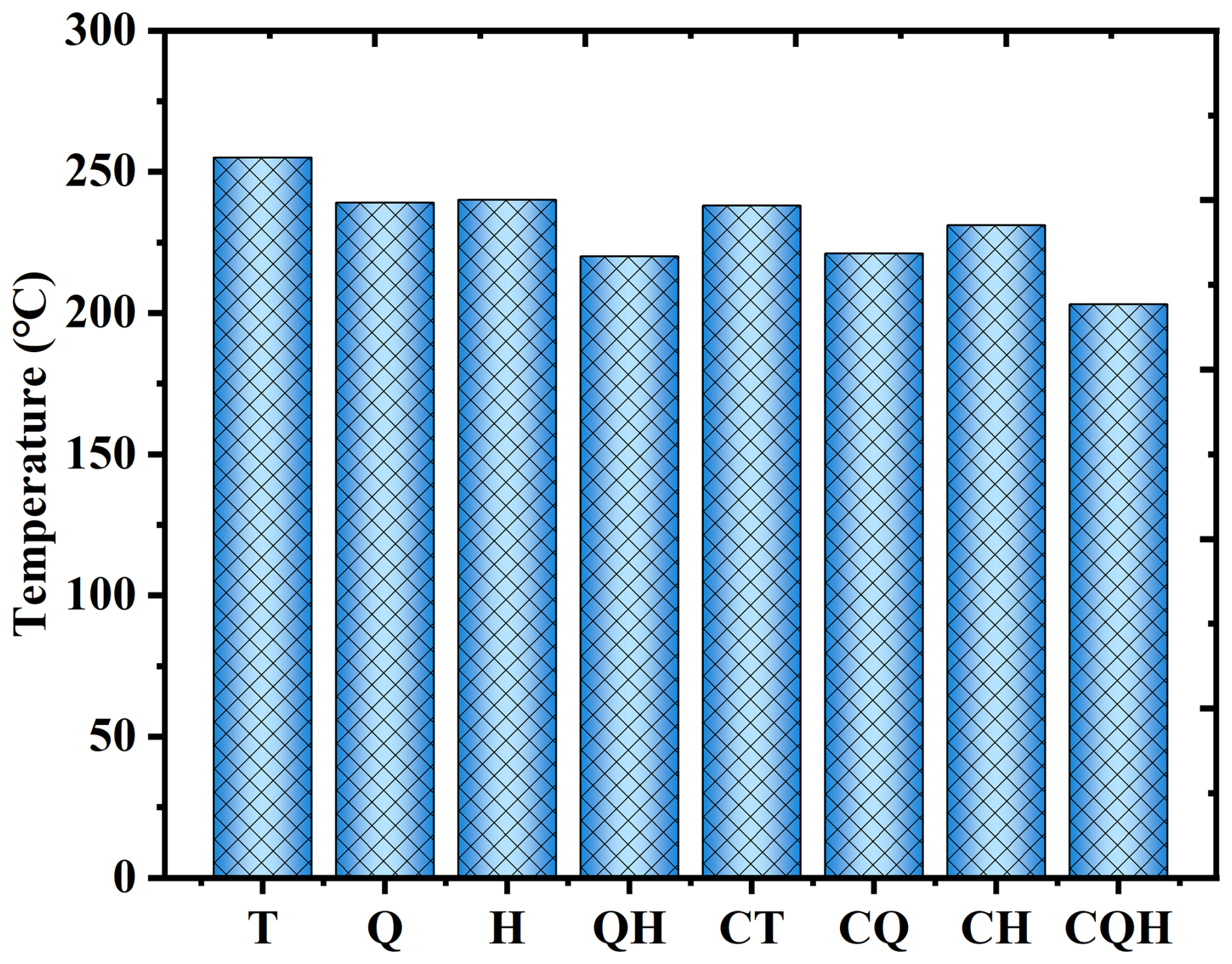
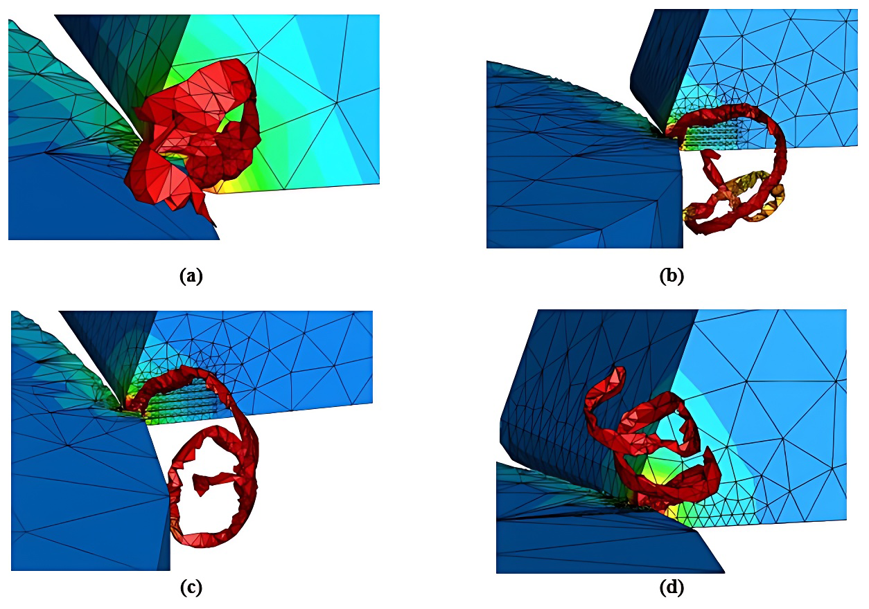
Figure 15Chip profile of the tool: (a) T tool chip morphology, (b) Q tool chip morphology, (c) H tool chip morphology, and (d) QH tool chip morphology.
Figure 11 shows the comparison between the cutting force with and without a coated micro-textured tool and conventional tool; it can be seen from Fig. 11a that all three micro-textured tools promoted the reduction in the cutting force compared to the conventional tool, in which the Q tool, H tool, and QH tool promoted the reduction in the cutting force of 15.40 %, 8.01 %, and 19.89 %, respectively. This is due to the fact that during the cutting process, the cutting area of the front face of the tool is in close contact with the cutting layer of the workpiece, and the presence of micro-texturing on the front face of the tool makes the contact area between the tool surface and the chip decrease, reducing the frictional resistance and promoting the reduction in the cutting force. Comparison between the three types of micro-textured structure tool found that the presence of micro-texture on the front and rear cutting surfaces at the same time to promote the reduction in the cutting force is significantly better than a single micro-texture tool. The presence of micro-texture on the front and rear cutting surfaces of the QH tool at the same time in the working area further reduces the contact area of the cutting area, thus reducing the friction force.
Figure 11b shows the graph of the effect of coated conventional tools and coated micro-textures on the cutting forces, from which it is clear that the coated micro-textured tools further promote the reduction in cutting forces as compared to the coated conventional tools, in which the coated CQ tools, coated CH tools, and coated CQH tools promote the reduction in cutting forces of 16.50 %, 7.55 %, and 21.57 %, respectively. It was also found that the cutting forces generated while cutting by the coated tools were significantly lower than those of the uncoated tools. This is due to the fact that the coated material has a lower coefficient of friction, which reduces the friction when the tool is in contact with the workpiece, resulting in a further reduction in the cutting force. At the same time, because the coating can improve the hardness and wear resistance of the tool surface, the wear rate of the tool is reduced, the service life of the tool is extended, and the stability and accuracy of cutting are improved.
Mises stress is an important measure of a material's strength and tensile capacity. It is not a real existing stress but a stress representation to describe the deformation behavior of a material under complex stress states. In engineering design and material evaluation, this equivalent stress can more accurately predict the yield and deformation behavior of materials. Figure 12 the Mises stress distribution on the surface of four types of tools. From the figure, it can be seen that the traditional tool Mises stress is more likely to be concentrated in the cutting area of the front face of the tool, and the high Mises stress will lead to localized wear and fatigue of the tool surface. This stress accelerates the wear process of the tool, especially under high speeds and heavy-load cutting conditions, which tends to cause fatigue cracks on the tool surface and reduce the tool life. For the three micro-textures, the high Mises stress is usually concentrated in the micro-texture site, which is due to the perpendicular relationship between the edge of the micro-texture and the tool surface, which is more likely to result in the concentration of Mises stress, and it can be seen that the micro-texture improves the location of the concentration of Mises stress on the tool surface.
4.3.2 Influence of lubrication state on cutting temperature
The cutting temperature is the result of the conversion of mechanical energy into thermal energy during the cutting process, and the cutting temperature is affected by a variety of factors, including cutting speed, feed rate, depth of cut, tool material, and lubrication conditions. The level of cutting temperature has an important impact on the machining process and tool performance, is an important evaluation index of cutting performance, so the cutting temperature generated by the tool in the simulation process is analyzed, Fig. 13 shows the distribution of cutting temperature on the surface of the traditional tool and micro-textured tool.
From the figure, it can be seen that for the traditional tool, the high-temperature region is concentrated in the tip of the tool, and gradually spreads to the interior, and the boundary between the high-temperature region and the low-temperature region is very obvious. For the micro-textured tool, the high-temperature region spreads to the micro-textured part because the micro-textured part is not in close contact with the chip, which makes the tool surface heat dissipation space larger and increases the heat exchange area on the tool surface, which makes the micro-textured tool have better heat dissipation conditions.
Figure 14 shows the comparison between cutting temperatures with and without coated tools, and from the figure, it can be seen that the cutting temperatures generated during the cutting simulation tests using the four uncoated tools are usually higher than the coated tools, where the coated tools with micro-textures on both front and rear tool faces generate the lowest cutting temperatures. Compared to uncoated conventional tools, Q, H, and QH tools promote a 6.27 %, 5.88 %, and 13.73 % decrease in cutting temperatures, respectively; compared to coated conventional tools, coated CQ, coated CH, and coated CQH tools show a 7.14 %, 2.94 %, and 7.56 % decrease in cutting temperatures, respectively. This is due to the fact that micro-texturing can help direct lubricant flow to the cutting zone more effectively during the cutting process, improving lubrication and further reducing friction and heat buildup. By reducing friction and heat, improving lubrication conditions, and enhancing cutting stability, micro-texturing can increase machining efficiency and productivity without sacrificing machining quality.
4.3.3 Influence of lubrication on chips
The chip is the material in processing, under the cutting action of the tool, with the material surface-layer plastic deformation and shear along the front corner of the tool surface, separated from the material in small pieces of material, i.e., waste. When cutting aluminum alloy, if the selected cutting dosage and tool materials are unreasonable, they will lead to poor chip morphology, affecting the friction of the tool surface will increase tool wear and reducing the cutting efficiency of the tool while shortening the service life of the tool; therefore, it is necessary to study the morphology of the chip. Figure 15 shows the chip morphology generated by four types of tools from which it can be seen that all four types of tools produce slender curly chips. Due to the presence of micro-texture on the tool surface, the cutting temperature are promoted to decrease, and as the cutting force decreases, the deformation of the workpiece removal-layer material decreases, and the friction on the tool surface decreases, which in turn affects the shaping of the chips. In addition, the coated micro-texture can promote the smooth discharge of chips and reduce the friction behavior of chips and tool surface. At the same time, the micro-textured part can be used as a storage container for tiny chips, avoiding the abrasive wear of the tool caused by tiny chips squeezing into the working area of the tool surface.
After the above simulation of aluminum alloy cutting with and without coated micro-texturing tools and conventional tools, it can be seen that the micro-texturing tools can promote the reduction in the cutting force and cutting temperature, and the coating material further enhances the cutting performance of the micro-texturing tools, in which the coating of the front and rear cutting surfaces are micro-texturing tools with optimal cutting performance.
In response to the carbide cutting tool aluminum alloy cutting force and machining accuracy and other issues, this paper, through the preparation of micro-textured structure in the front face of the tool and the use of the micro-textured structure of the role of the mechanism to optimize the cutting performance of the tool and, in the surface of the tool near the coating treatment, to explore the micro-textured structure and lubrication state of the impact on the cutting performance of the research, we find the following:
-
Through nine groups of cutting aluminum alloy cutting orthogonal test and cutting force and surface roughness of the polar analysis, it can be seen that the cutting force impact is, from large to small, on the depth of cut, feed, cutting speed and that the surface roughness impact is, from large to small, on for the feed, depth of cut, cutting speed.
-
Through the cutting simulation of three micro-texturing tools and conventional tools, it can be seen that the tool with micro-texturing on both the front and the back surfaces promotes a 19.89 % decrease in cutting force and a 13.73 % decrease in cutting temperature, which is superior to the other two kinds of micro-texturing tools and conventional tools in terms of its cutting performance.
-
By way of coating treatment on the surface of the tool, cutting simulation tests of coated conventional tools and coated micro-textured tools, it is found that the coating material further promotes the cutting performance of the front-and-back micro-textured tools, promoting a 21.57 % decrease in cutting force and a 7.56 % decrease in cutting temperature, and at the same time, the coating material and the micro-textures synergistically promote the outflow of chips to avoid the cutting heat on the surface of the tool buildup.
| Vc | cutting speed |
| f | feed |
| ap | cutting depth |
| FN | load on the contact surface |
| σs | extruded yield limit of the contact material |
| A | actual contact area between the tool and the workpiece |
| Ff | friction generated during cutting |
| τs | shear strength |
| μ | friction coefficient |
| actual contact length of the tool chip | |
| Lf | theoretical contact length of the tool chip |
| l0 | width of the micro-texture |
| n | number of micro-textures in the contact area of the tool chip |
| ac | width of the cut |
| ψr | residual deflection angle |
| β | friction angle |
| γ0 | leading angle of the tool |
| ψλ | outflow angle of the chip |
| Fx | axial force |
| Fy | radial force |
| Fz | main cutting force |
| T | conventional tool |
| Q | front-facing grooved micro-textured tool |
| H | back-facing grooved micro-textured tool |
| QH | front-and-back-facing grooved micro-textured tool |
| CT | coated conventional tool |
| CQ | coated front-facing grooved micro-textured tool |
| CF | coated back-facing grooved micro-textured tool |
| CQH | coated front- and back-facing grooved micro-textured tool |
Data will be made available on request.
TX constructed the overall framework of the paper and wrote the paper; LX completed the corresponding data analysis and performed the validation; CM performed data curation and visualization; and QL developed the methodology, supervised the research, and reviewed and edited the paper.
The contact author has declared that none of the authors has any competing interests.
Publisher's note: Copernicus Publications remains neutral with regard to jurisdictional claims made in the text, published maps, institutional affiliations, or any other geographical representation in this paper. While Copernicus Publications makes every effort to include appropriate place names, the final responsibility lies with the authors.
The authors are grateful to the anonymous reviewers and the editor for their comments on and suggestions for improving our paper. Here we need to thank the following organizations for their strong support: Jilin Provincial Department of Education.
This research has been supported by the Jilin Provincial Department of Education (grant no. 2024LY501L08).
This paper was edited by Xichun Luo and reviewed by two anonymous referees.
Duan, Z., Chen, L., and Li, B.: Effect of micro-textured morphology with different wettabilities on tool cutting performance, Int. J. Adv. Manuf. Tech., 123, 1745–1754, https://doi.org/10.1007/s00170-022-10284-2, 2022.
Fouathiya, A., Meziani, S., Sahli, M., and Barrière, T.: Experimental investigation of microtextured cutting tool performance in titanium alloy via turning, J. Manuf. Process., 69, 33–46, https://doi.org/10.1016/j.jmapro.2021.07.030, 2021.
Guo, D., Wang, D., Wu, S., Qi, H., and Saetang, V.: Investigation on turning of Inconel 718 using differently coated microtextured tools, P. I. Mech. Eng. E-J. Pro., 239, 754–764, https://doi.org/10.1177/09544089231191720, 2023.
Hao, X., Sun, H., Wang, L., Ali, Q., Li, L., and He, N.: Fabrication of micro-texture on cylindrical inner surface 25 and its effect on the stability of hybrid bearing, Int. J. Adv. Manuf. Tech., 109, 1671–1680, https://doi.org/10.1007/s00170-020-05750-8, 2020.
Lin, Z. and Hong, M.: Femtosecond Laser Precision Engineering: From Micron, Submicron, to Nanoscale, Ultrafast Science, 2021, https://doi.org/10.34133/2021/9783514, 2021.
Orra, K. and Choudhury, S. K.: Tribological aspects of various geometrically shaped micro-textures on cutting insert to improve tool life in hard turning process, J. Manuf. Process., 31, 502–513, https://doi.org/10.1016/j.jmapro.2017.12.005, 2018.
Rosas, J., Lopes, H., Guimarães, B., Piloto, P. A., Miranda, G., Silva, F. S., and Paiva, O. C.: Influence of Micro-Textures on Cutting Insert Heat Dissipation, Appl. Sci., 12, 6583, https://doi.org/10.3390/app12136583, 2022.
Salur, E., Kuntoğlu, M., Aslan, A., and Pimenov, D. Y.: The Effects of MQL and Dry Environments on Tool Wear, Cutting Temperature, and Power Consumption during End Milling of AISI 1040 Steel, Metals, 11, 1674, https://doi.org/10.3390/met11111674, 2021.
Sharma, R., Pradhan, S., and Bathe, R. N.: Design and fabrication of honeycomb micro-texture using femtosecond laser machine, Mater. Manuf. Process., 36, 1314–1322, https://doi.org/10.1080/10426914.2021.1906898, 2021.
Şirin, Ş., Sarıkaya, M., Yıldırım, Ç. V., and Kıvak, T.: Machinability performance of nickel alloy X-750 with SiAlON ceramic cutting tool under dry, MQL and hBN mixed nanofluid-MQL, Tribol. Int., 153, 106673, https://doi.org/10.1016/j.triboint.2020.106673, 2021.
Škamat, J., Černašėjus, O., Zhetessova, G., Nikonova, T., Zharkevich, O., and Višniakov, N.: Effect of Laser Processing Parameters on Microstructure, Hardness and Tribology of NiCrCoFeCBSi/WC Coatings, Materials, 14, 6034, https://doi.org/10.3390/ma14206034, 2021.
Su, S., Wang, C., Mi, G., Xiong, L., Zhang, W., and Wang, J.: A study of the effect of laser micro-texture on bond strength and fracture mechanism of paint layer, Mater. Chem. Phys., 309, 128411, https://doi.org/10.1016/j.matchemphys.2023.128411, 2023.
Sun, X., Wang, X., Hu, Y., and Duan, J. A.: The effect of micro-texture on wear resistance of WC/Co-based tools during cutting Ti-6Al-4V, Appl. Phys. A, 127, 453, https://doi.org/10.1007/s00339-021-04576-9, 2021.
Sundar, A. S., Kar, A., Mugada, K. K., and Kumar, A.: Enhancement of microstructure, micro-texture, and mechanical properties of Al6061 friction stir welds using the developed static shoulder welding tool, Mater. Charact., 203, 113148, https://doi.org/10.1016/j.matchar.2023.113148, 2023.
Szczotkarz, N., Mrugalski, R., Maruda, R. W., Królczyk, G. M., Legutko, S., Leksycki, K., Dębowski, D., and Pruncu, C. I.: Cutting tool wear in turning 316L stainless steel in the conditions of minimized lubrication, Tribol. Int., 156, 106813, https://doi.org/10.1016/j.triboint.2020.106813, 2021.
Tang, S., Liu, P., Su, Z., Lei, Y., Liu, Q., and Liu, D.: Preparation and cutting performance of nano-scaled Al2O3-coated micro-textured cutting tool prepared by atomic layer deposition, High Temp. Mater. Proc., 40, 77–86, https://doi.org/10.1515/htmp-2021-0021, 2021.
Wang, D., Zhang, Z., Kollmann, J., and Oeser, M.: Development of aggregate micro-texture during polishing and correlation with skid resistance, Int. J. Pavement Eng., 21, 629–641, https://doi.org/10.1080/10298436.2018.1502436, 2020.
Wang, D., Yin, H., and Feng, L.: Study on the effect of micro-texture coating tool on the milling quality of wood surface, Lubr. Sci., 36, 387–395, https://doi.org/10.1002/ls.1699, 2024.
Wang, J., Bai, X., Shen, X., Liu, X., and Wang, B.: Effect of micro-texture on substrate surface on adhesion performance of electroless NiP coating, J. Manuf. Process., 74, 296–307, https://doi.org/10.1016/j.jmapro.2021.12.025, 2022.
Wang, Q., Yang, Y., Yao, P., Zhang, Z., Yu, S., Zhu, H., and Huang, C.: Friction and cutting characteristics of micro-textured diamond tools fabricated with femtosecond laser, Tribol. Int., 154, 106720, https://doi.org/10.1016/j.triboint.2020.106720, 2021.
Wu, J., Zhao, J., Qiao, H., Hu, X., and Yang, Y.: The New Technologies Developed from Laser Shock Processing, Materials, 1, 1453, https://doi.org/10.3390/ma13061453, 2020.
Wu, X., Zhan, J., and Mei, S.: Optimization of Micro-Texturing Process Parameters of TiAlN Coated Cutting Tools by Femtosecond Laser, Materials, 15, 6519, https://doi.org/10.3390/ma15196519, 2022.
Xin, T., Pei, H., and Shucai, Y.: Coating and micro-texture techniques for cutting tools, J. Mater. Sci., 57, 17052–17104, https://doi.org/10.1007/s10853-022-07704-9, 2022.
Yang, S., Zhou, Y., Zhang, Y., Tong, X., and Liu, W.: Prediction of surface roughness for milling titanium alloys by microweave configuration ball end milling cutters, Journal of Harbin Institute of Technology, 22, 141–146, https://doi.org/10.15938/j.jhust.2017.03.026, 2017.
Yang, X., Fu, Y., Ji, J., Chen, T., and Pan, C.: Study on tribological properties of surface concave convex micro-texture on the mold steel, Ind. Lubr. Tribol., 72, 1167–1171, https://doi.org/10.1108/ILT-03-2020-0081, 2020.
Yu, Q., Zhang, X., Miao, X., Liu, X., and Zhang, L.: Performances of concave and convex microtexture tools in turning of Ti6Al4V with lubrication, Int. J. Adv. Manuf. Tech., 109, 1071–1092, https://doi.org/10.1007/s00170-020-05656-5, 2020.
- Abstract
- Introduction
- Carbide cutting tool aluminum alloy test
- Theoretical analyses
- Simulation of aluminum alloy cutting by coated micro-textured tools
- Conclusions
- Appendix A: List of abbreviations
- Data availability
- Author contributions
- Competing interests
- Disclaimer
- Acknowledgements
- Financial support
- Review statement
- References