the Creative Commons Attribution 4.0 License.
the Creative Commons Attribution 4.0 License.
 | 19 Feb 2024
Improved flux linkage observer for position estimation of permanent magnet synchronous linear motor
Wenbin Yu
Guolai Yang
Liqun Wang
Darui Lin
Ahmed Al-Zahrani
With the development of motor technology, sensorless control attracts more and more attention. In this paper, an improved flux linkage observer is proposed to overcome issues including inaccurate initial positions and sampling noise. The voltage and current models are combined, and a sliding-mode observer is designed based on the hybrid model to obtain the compensation voltage. Therefore, the estimated flux linkage after compensation can greatly resist the influence caused by inaccurate initial positions or sampling noise. Phase-locked loop technology is used to process the estimated flux linkage to get the stable estimated speed and position. The proposed scheme has a simple structure and only one parameter. It is easy to use and adjust in practice. The simulation and experimental results verify that the proposed algorithm is effective, and the estimated flux linkage and position is accurate with an inaccurate initial position.
- Article
(4911 KB) - Full-text XML
- BibTeX
- EndNote


Permanent magnet synchronous linear motors (PMSLMs) are widely used in various fields such as precision machining, oilfield equipment, rail transportation, etc. due to their special motion, high thrust density and high motion accuracy (Cao et al., 2015; Pellegrino et al., 2012). Because of the unique structure, a long-enough position detection system is always needed in PMSLMs for a good control performance (Lin et al., 2021). On the other hand, linear position encoders are susceptible to damage and need regular maintenance (Cao et al., 2019; Lu et al., 2011). Especially in harsh environments, external impacts or collisions very easily damage the linear position encoder and make the system unable to work properly. These all greatly limit the application and development of PMSLMs. Therefore, a sensorless control algorithm is of great significance to the PMSLM.
With the development, many sensorless control algorithms have been proposed to estimate the speed and position of rotors accurately. Some scholars achieved real-time estimation by injecting high-frequency pulse signals at zero or low speed (Wang et al., 2019; Ofori et al., 2015). This method makes use of the salient effect of the motor and analyzes the current response, which carries position information. However, this method is powerless for the motor whose salient effect is not obvious, and the high-frequency signal also increases the loss. Model reference adaptation (Cirrincione et al., 2013; Cheng et al., 2015), Kalman filtering (Pasqualotto et al., 2023; Lu et al., 2011), state observer (Accetta et al., 2014; Zhang et al., 2020) and other methods based on intelligent-control theory establish the rotor state observer according to the motor mathematical model and adjust the model in real time according to the operating state to accurately estimate the speed and position. These methods have strong robustness and anti-interference ability and are suitable for observing the motor state under long-term operation. On the other hand, the algorithms are also complex and require high computing capacity. The estimation effect at low speeds is also not ideal. The position estimation based on back electromotive force (EMF) has the advantages of simple structure, less calculation and fast response, but it also has the problems of low detection accuracy and being easily affected by a change in motor parameters (Hussain and Toliyat, 2015; Zhang et al., 2021; Wang and Ge, 2010). Especially at low speeds, the back EMF is too small, which makes the speed and position estimations more sensitive to noise. The position estimation based on flux linkage is simple in structure and is easy to implement. The integration process greatly reduces the influence of current noise, but it also increases the influence of direct current (DC) bias. The open-loop detection method also makes the algorithm less anti-interference oriented (Zhao et al., 2019; Xiao et al., 2021). Each method has its advantages and disadvantages. To establish a suitable sensorless position estimation algorithm and to increase the reliability and anti-interference ability on the basis of simple structure and less computation is also one of the purposes of this paper.
It is a key step to obtain the stator flux linkage by integrating the back EMF of the motor. Theoretically, the flux linkage obtained by integrating the back EMF can still work properly even at low speeds. For the DC bias and high-frequency noise of the current sensor (Pavlitov et al., 2014; Du et al., 2020), some scholars design various types of high-pass or low-pass filters to eliminate the impact (Cupertino et al., 2010; Xiao et al., 2017). Although it brings amplitude attenuation and phase offset, it also achieves good practical results. In fact, the integral process for the flux linkage always requires an accurate initial value of the flux linkage, i.e., the exact initial position of the motor. The inaccurate initial value of integration will lead to errors in the flux linkage estimation and have a negligible effect on the speed and position estimation, which has not been considered in much of the literature (Wang et al., 2012; Yang et al., 2022; Ting et al., 2019). In practical applications, due to the external interference, the direct drive of PMSLMs is more likely to lead to inaccurate initial positions. When the inaccurate initial position is used to calculate the flux linkage, error occurs, which will affect the speed and position estimation.
To solve this problem and establish a position estimation scheme with good performance, an improved flux linkage observer is proposed in this paper. Sliding-mode control is widely known and used for its good robustness and anti-interference capacity (Afifa et al., 2023). The same sliding-mode observer is also famous because of its strong nonlinearity. Sliding-mode theory can always have a good performance in nonlinearity issues, and it can also be used in this paper. Different from the traditional open-loop calculation method, the flux linkage is calculated through the voltage model firstly and then uses the inaccurate flux linkage to estimate the current through the current model. Finally, a sliding-mode observer is established based on the estimated current and the actual current, and the output is applied to the voltage model as the compensation voltage to form a closed-loop structure. The output of the sliding-mode observer, as the compensation voltage, is used to correct the inaccurate flux linkage. Then, the inaccurate flux linkage will tend towards the actual value under the action of the sliding-mode observer. Compared to the other observers, the proposed observer has the advantages of a simple structure, only one parameter, reliable anti-interference and being easy to implement. The widely known and annoying chattering problem caused by a nonlinear sliding-mode function (Ahmad et al., 2023) can also be effectively suppressed because of the integral item in the modified flux linkage.
Section 1 of this paper is an overview of position estimation and puts forward the existing problems. Section 2 describes the voltage, current model and common position calculation method of the motor. In Sect. 3, the improved flux linkage observer algorithm proposed in this paper is analyzed, and its stability is proved. Sections 4 and 5 simulate and experiment with the proposed flux linkage observer to further illustrate its performance. Section 6 summarizes the full paper.
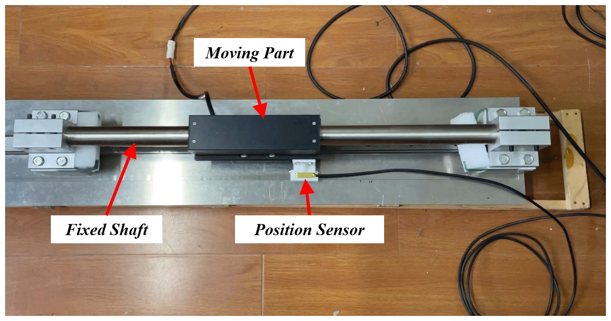
The motor used in this paper is a surface-mounted PMSLM shown in Fig. 1. The windings are internal in the moving part, and permanent magnets are also internal in the fixed shaft. Injecting current into the windings, the moving part can move along the shaft. For good control performance, the position sensor is always needed and should cover the full length. As mentioned before, position information will be replaced by a sensorless scheme in this paper. To simplify the analysis, there are some assumptions that we have outlined below:
- a.
all three phases of the motor have the same resistance and inductance;
- b.
the mutual inductance of the windings are ignored;
- c.
electromagnetic losses and eddy current effects are ignored.
These simplifications are acceptable and reasonable for the topic in this paper because, under normal operating conditions, the influences of these factors are very small and can be ignored (Zhang et al., 2016). The composite flux linkage produced by permanent magnets and windings is called stator flux linkage, and that produced by permanent magnets is called rotor flux linkage. The two-phase voltage model in a static coordinate system can be expressed as
The stator current model in static coordinate system can be expressed as
According to Eq. (1),
Calculate the stator flux linkage from Eq. (3) and substitute the result into Eq. (2) to obtain the position angle:
The electrical angle can be obtained from Eq. (4), and the actual rotor angle is . For linear motors, the actual movement position should be expressed as
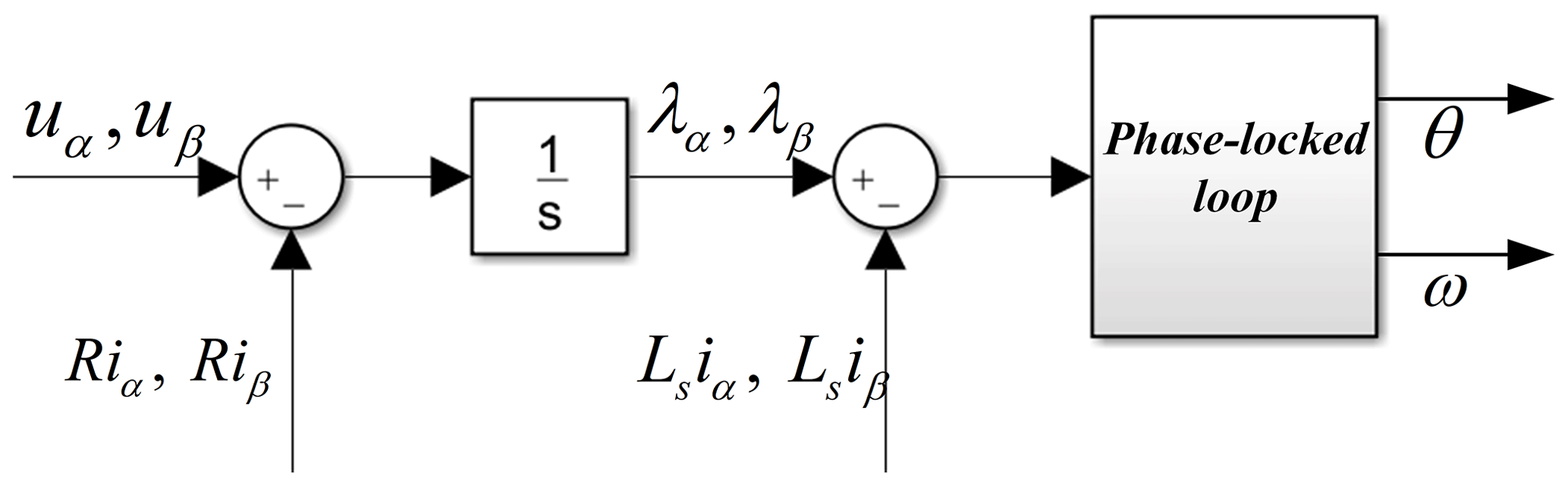
Actually, the noise in the current and voltage signal makes the estimated position and speed directly calculated by arctangent very rough. Therefore, the phase-locked loop technology is used in this paper instead of Eq. (4) to obtain a smooth estimated position and speed. The traditional position estimation method based on stator flux linkage and phase-locked loop (PLL) is shown in Fig. 2. To eliminate the influence of DC bias, current and voltage measurement noise, other forms of transfer functions are used to replace the pure integration (Pavlitov et al., 2014; Xiao et al., 2017), and this has achieved good results. Little attention has been paid to the problem of an inaccurate initial position of the motor in the literature.
3.1 Flux linkage error analysis and observer
To solve the problem of the initial estimated position being inaccurate due to uncertain interference, the traditional method of stator flux linkage estimation is improved upon in this section. For voltage error caused by inverter nonlinearity, noise in the measuring current, inaccurate initial-phase angle and other interference factors, Eq. (3) can be rewritten as
Flux linkages λα and λβ are affected by errors of voltage, current and initial value of flux linkage. The integral initial-value error of the stator flux linkage of the αβ axis may be caused by the inaccurate initial-position estimation, or it may be caused by the inconsistency between the actual value and the motor flux linkage mark. This results in a fixed offset of the estimated flux linkage value. To calculate the stator flux linkage more accurately, it is necessary to compensate for these errors.
Although Δλα0 and Δλβ0 are fixed, it still can be expressed as a form of the integral of nonlinear time-varying functions δα and δβ.
Let
Thus, Eq. (6) can be further expressed as
For various possible errors, there is both eα and eβ in the flux linkage calculation, and they are always unknown. Actually, the estimated flux linkages and are calculated by Eq. (9) without eα and eβ so that, if the compensation voltage eα and eβ can be observed, the estimated flux linkage will be more accurate.
By combining Eqs. (2) and (9), the two-phase current in the static coordinate system calculated by estimated flux linkage can be expressed as
For various errors caused by nonlinear factors in Eq. (6), a sliding-mode observer is established using the estimated current and actual current to calculate the compensation voltage. The sliding-mode function and sliding-mode observer are expressed as
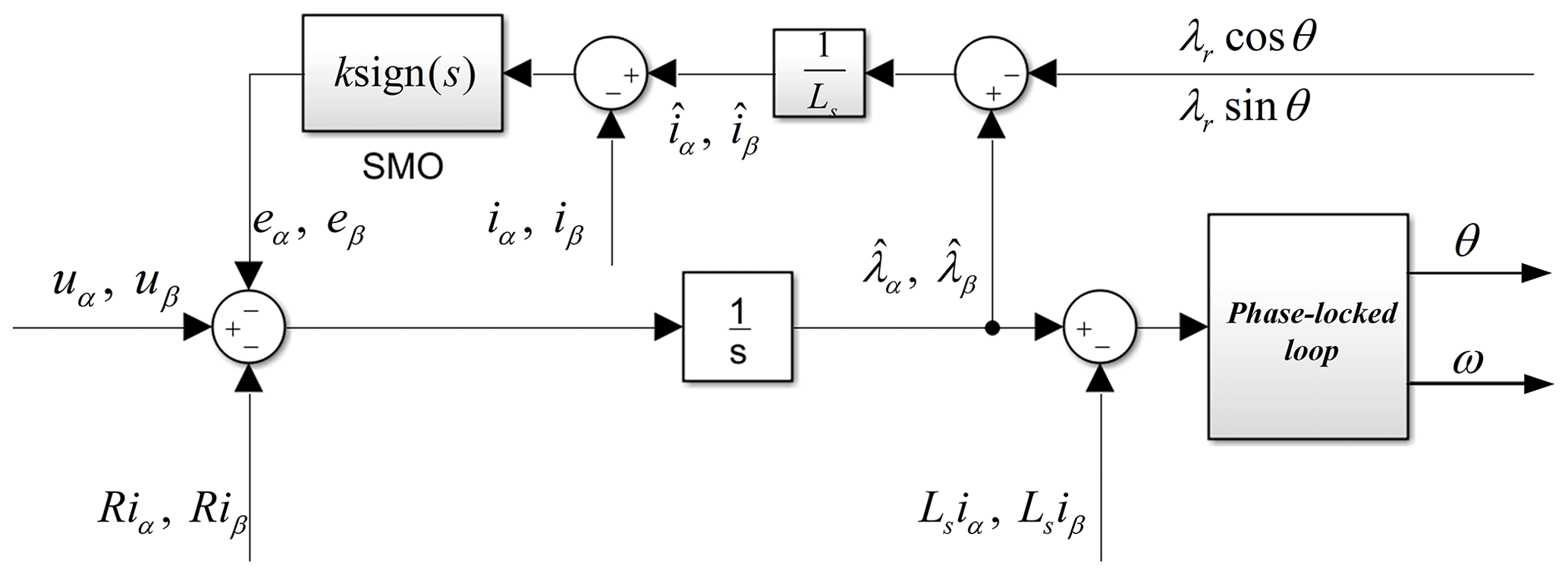
When the error in the system is suppressed by the compensation voltage, the estimated flux linkage will be consistent with the actual value, and the estimated current will also be consistent with the actual value. The improved flux linkage estimation scheme is shown in Fig. 3. The proposed observer is simple in structure, is easy to implement, and has only one parameter. It is very suitable for practical applications and has significant advantages.
3.2 Proof of stability
Taking the α axis as an example, the stability of the flux linkage observer is proved by the Lyapunov function. We construct the function and its first derivative as
Obviously, the Vα is greater than zero.
According to Eqs. (9) and (10), the estimated current is
We substitute Eqs. (11) and (12) into Eq. (15):
We differentiate Eq. (16):
We substitute Eq. (17) into Eq. (14):
From Eq. (18), if , there is
When the sliding-mode coefficient k satisfies Eq. (19), the compensation voltage obtained by the constructed sliding-mode observer will make the estimated current converge with the actual current, and the estimated flux linkage will converge with the actual flux linkage.
According to Eqs. (1) and (2),
Substituting Eq. (20) into Eq. (19), we can get
In addition, according to Eqs. (9) and (12), the estimated flux linkage and the compensation voltage eα have
During the operation of the motor, the stator flux linkage always changes in a sine or cosine manner. The α-axis estimated flux linkage can be expressed as
From Eqs. (22) and (23), there is
As the sliding-mode coefficient approaches or exceeds the maximum amplitude of the back EMF, the compensation voltage will become the main signal, and its effect will be greater than that of the back EMF. To ensure the main function of the back EMF, the sliding-mode coefficient k should also satisfy k<ωλr. Therefore, if , the compensation voltage obtained by the sliding-mode observer can make the estimated flux linkage converge to the actual value λα, and the proof of the β axis is same.
The improved flux linkage observer proposed in this paper has a good suppression effect on the inaccurate position estimation caused by the high-frequency noise of voltage and current, uncertain interference, and inaccurate initial position and has a good anti-interference capacity and stability. Next, the proposed observer will be verified by simulation and experiments.
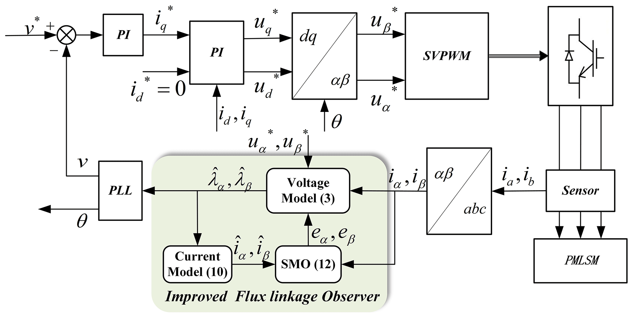
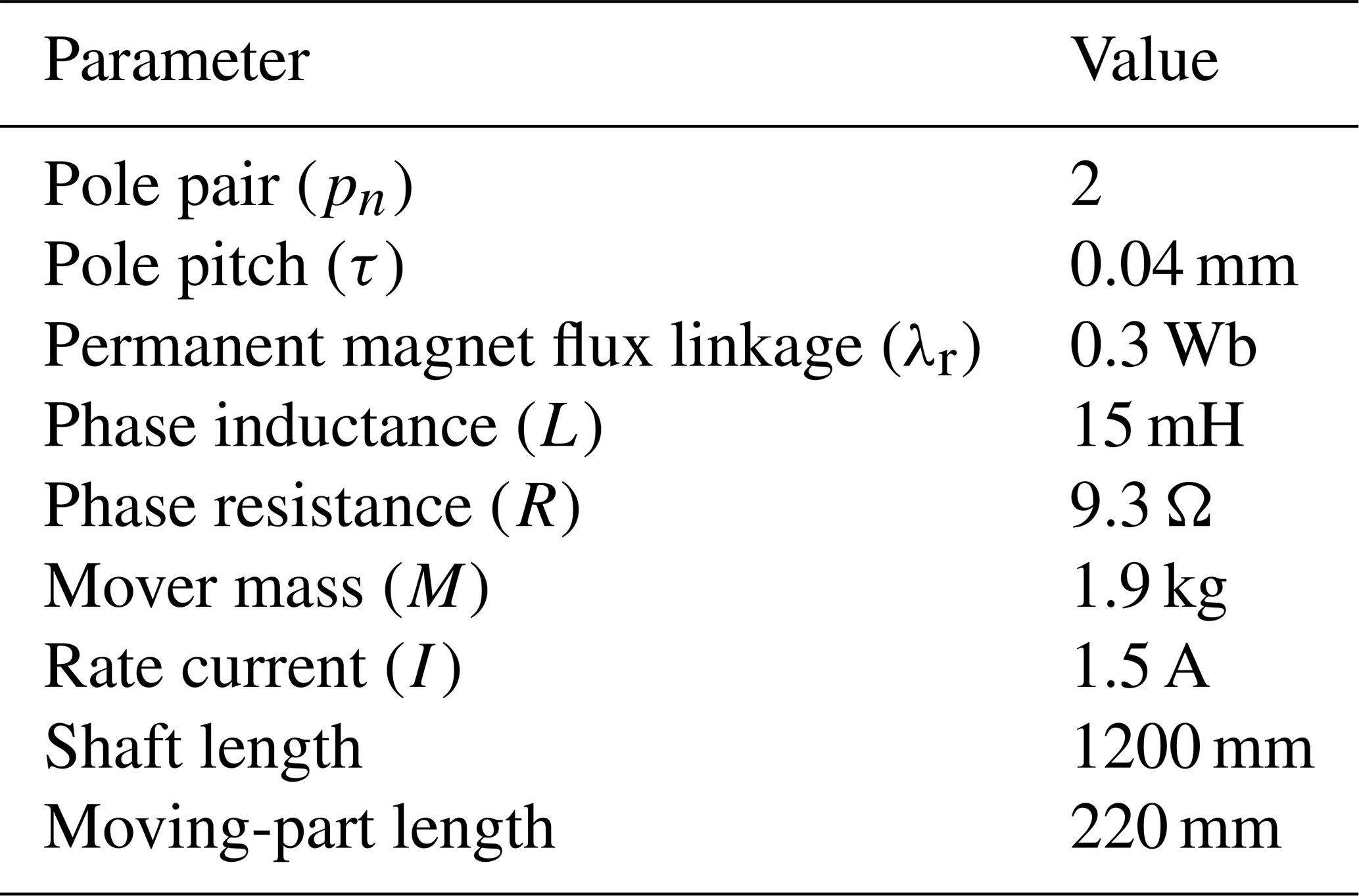
To further examine the actual performance of the improved observer, some simulations are carried out according to the mathematical model of PMSLMs. The MATLAB/Simulink is used in this paper, and its version is 2016b. The common space vector pulse width modulation (SVPWM) drive scheme is used to control the motor, and the frequency of the inverter is 10 kHz. The controller adopts a simple PI controller, including speed loop control and current loop control. The control system is shown in Fig. 4, and the motor parameters are shown in Table 1. Actually, the proposed flux linkage observer only needs the voltage and current of the αβ axis to estimate the position. The current data are sampled by the current sensor. The voltages uα and uβ are replaced by the control voltages and . Due to the nonlinear effect of the inverter, there is a delay and error between the expected voltage and the actual voltage. Much of the literature has studied the characteristics of inverter and proposed voltage compensation schemes. The flux linkage observer proposed in this paper classifies it as voltage error disturbance, which can also be well compensated for by the nonlinear sliding-mode observer and can be easily implemented.
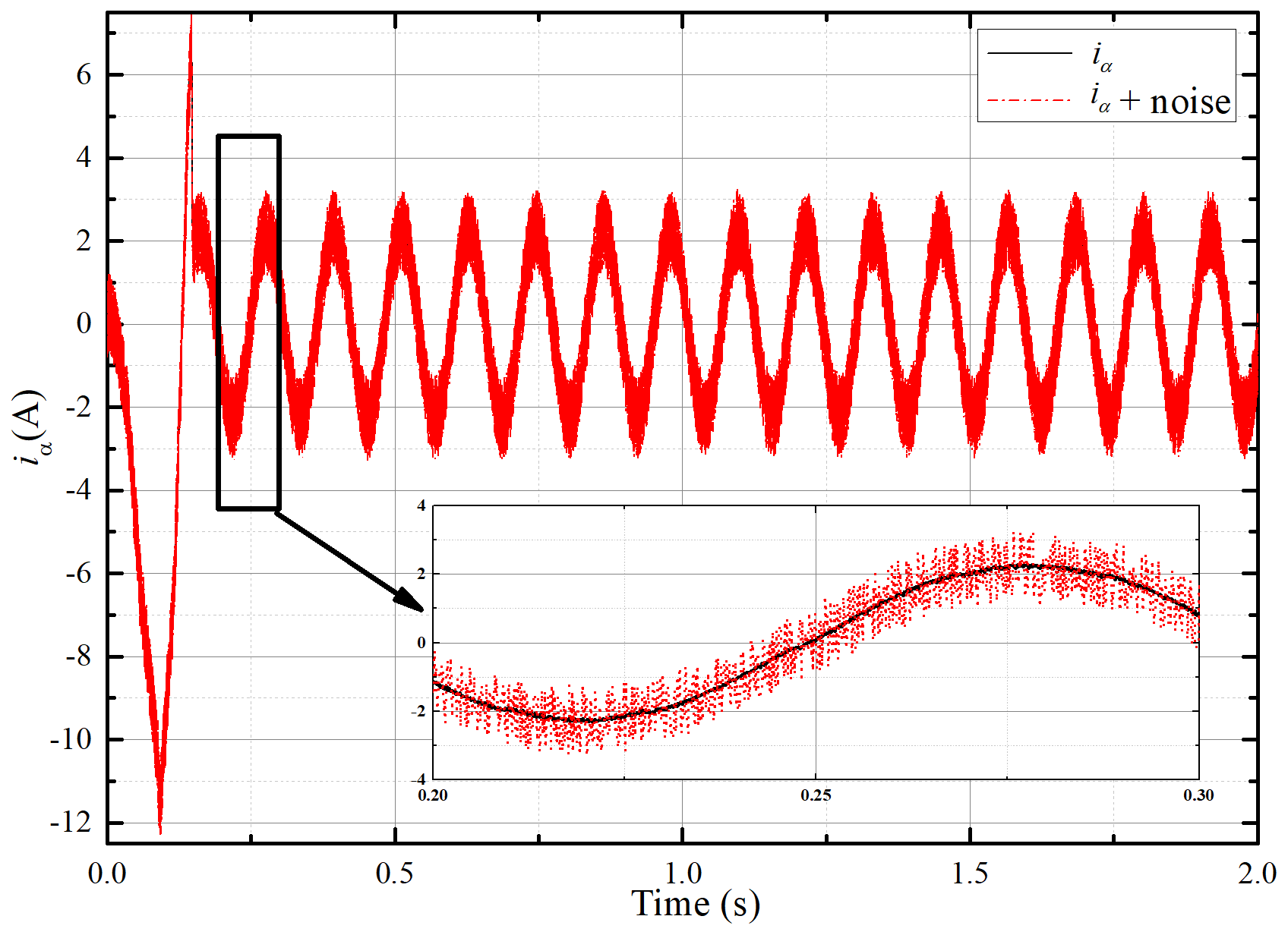
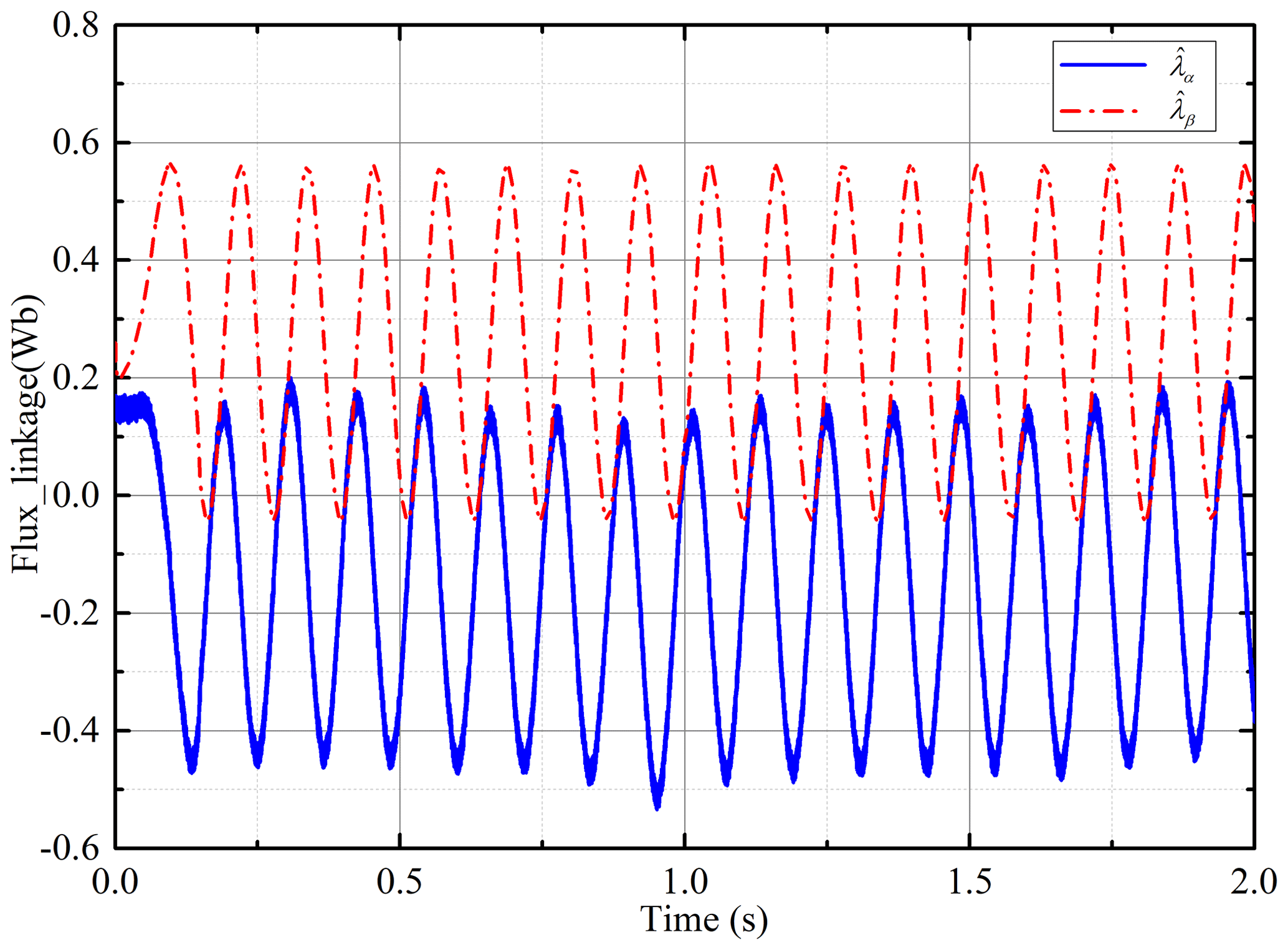
To simulate the possible current noise in actuality, a random disturbance with amplitude 1 A is added to the currentiα. The actual current and the current added random noise are shown in Fig. 5. It can be found that random noise accounts for a large proportion of the output current. Actually, the current noise will not be so large; this is to simulate a sufficiently bad situation. The initial position of the d axis is zero at the beginning – i.e., λα=λr, λβ=0 in Eq. (3). This can also be expressed as λα=λrcos θ0, λβ=λrsin θ0, θ0=0. In fact, the initial position of the motor cannot always be obtained accurately, which results in the difference between the integral initial value of the stator flux linkage set by the controller and the actual value. It makes the estimated flux linkage difficult to calculate accurately. For this problem, the estimated position of the d axis is set as 60∘ in the simulation. Then, the initial flux linkage errors Δλα0 and Δλβ0 in Eq. (6) can be obtained. The convention voltage or current models demonstrate difficulty in dealing with these adverse conditions effectively. The estimated flux linkages and under the convention way are shown in Fig. 6, which shows that the error is very large. The estimated speed and position are completely unusable.
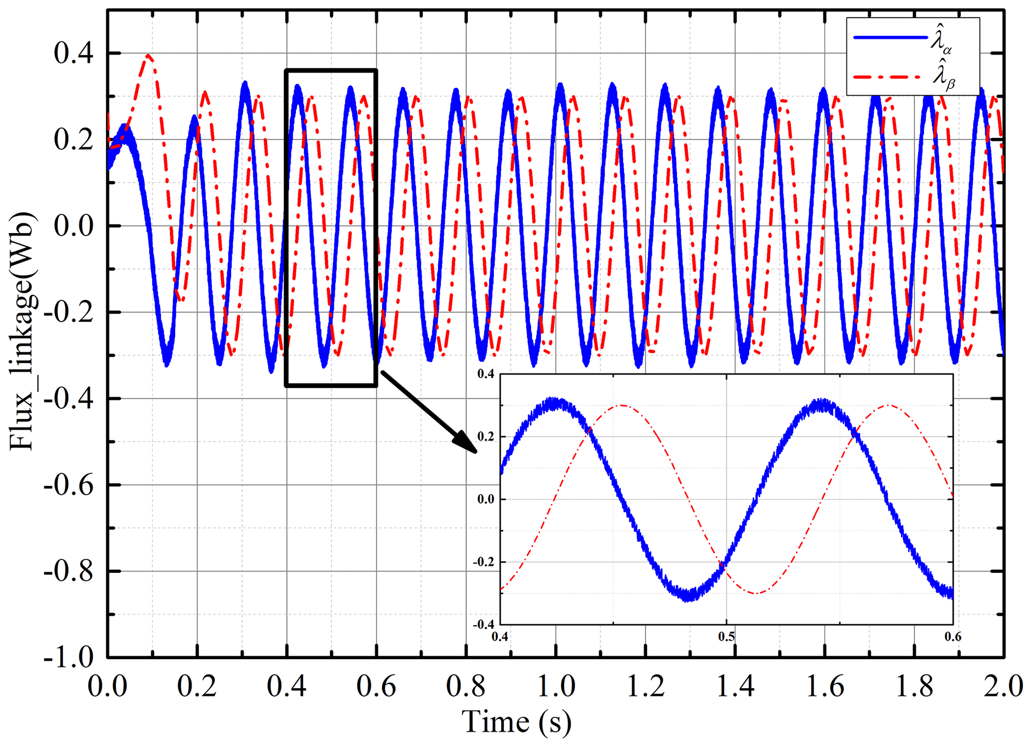
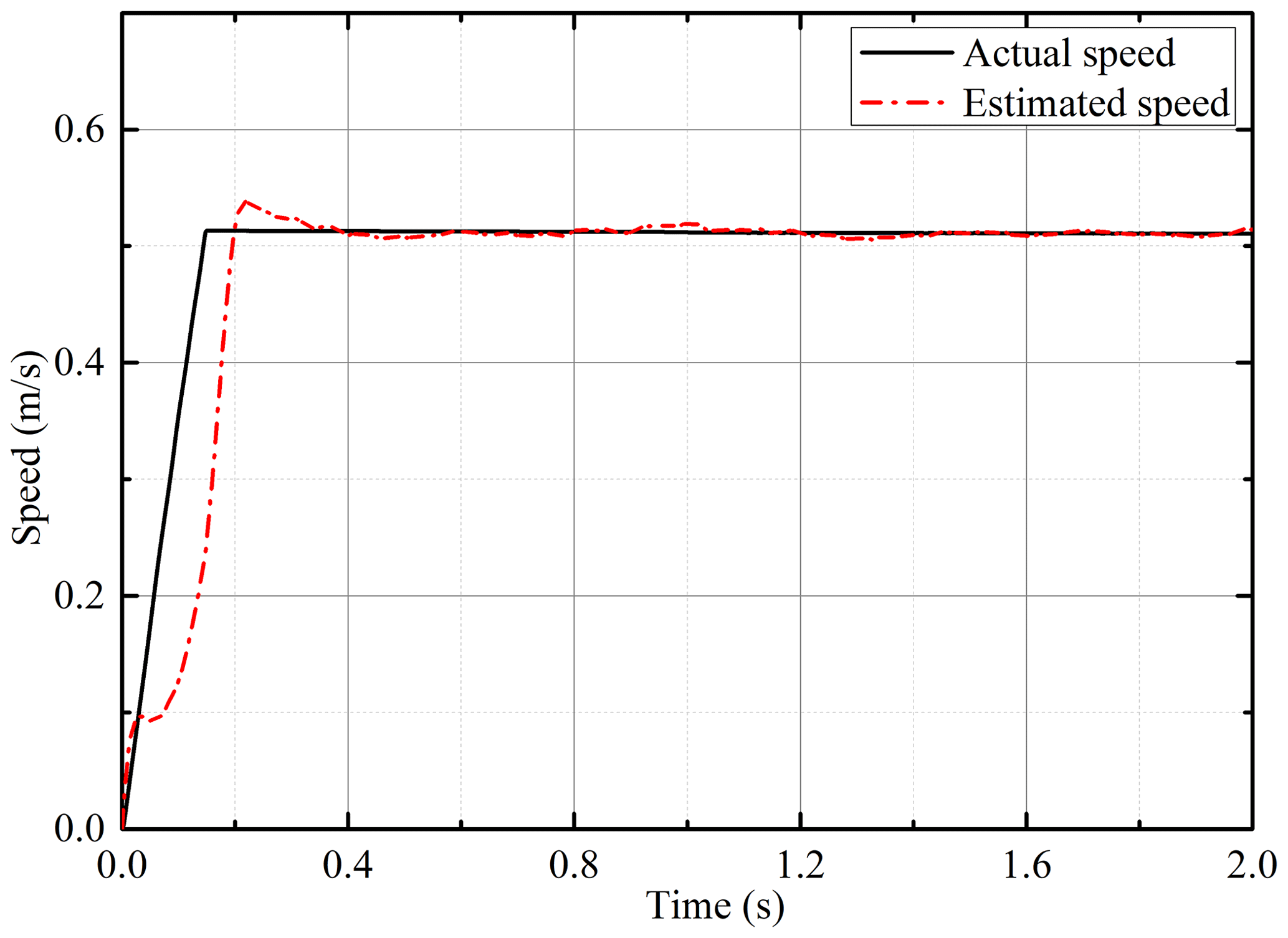
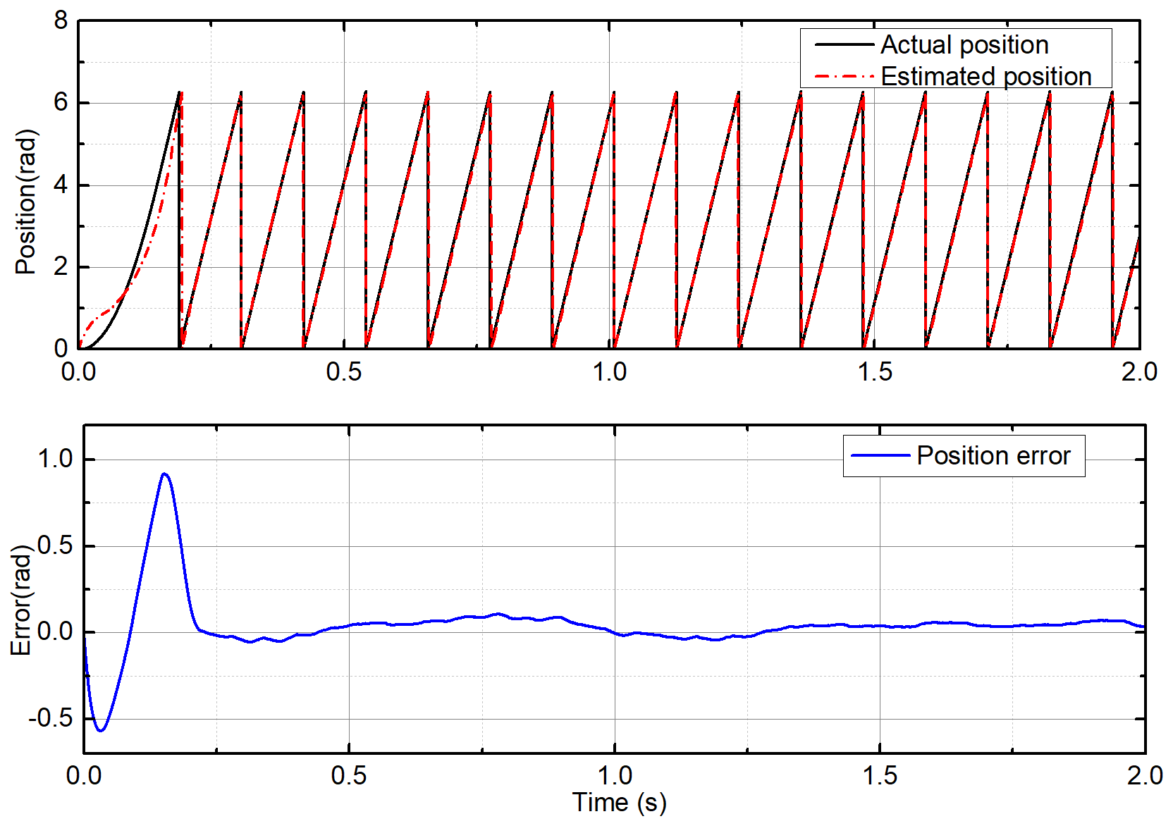
Using the improved flux linkage observer proposed in this paper, simulations are performed under constant load and uniform speed. The estimation of the flux linkage is shown in Fig. 7. Under the influence of the current noise and the error of the integral initial value, the estimated value of the flux linkage can still converge to the true value and stabilize quickly. The estimated speed of the PMSLM is shown in Fig. 8. In the initial stage of motor start-up, the estimated speed can quickly and stably converge to the actual value after a short adjustment. The estimated position and position errors are shown in Fig. 9. Similarly, in the initial stage of start-up, the position error is large. After a short adjustment, the estimated position can keep up with the actual position steadily, and the error can converge to near zero.
Because of the fixed coefficient k in the sliding-mode observer, the current error is difficult to maintain at zero all the time when approaching the steady state. Therefore, the compensation voltage has high-frequency chattering. This is also the common issue with the sliding-mode theory. However, the integration process in flux linkage calculation has largely eliminated this high-frequency chattering. We can find that the sliding-mode observer combined with the flux linkage estimation is very effective. There is no need to do more processing for the chattering. This is also the advantage of the improved scheme in this paper. As the coefficient k is small, it means that more fine adjustment can be obtained, but it will also affect the convergence speed.
Under the condition of variable speeds, the proposed observer is simulated and tested. The speed of the PMSLM changes from 0.5 to 0.7 m s−1 at 1 s. As shown in Fig. 10, the estimated flux linkage converges to the actual value after a short adjustment at the beginning. At 1 s, the sudden change in speed changes the estimated flux linkage, but it quickly stabilizes again. The estimated speed is shown in Fig. 11, and it can track the actual speed well. When the actual speed changes, the estimated speed also has a good dynamic respond. Figure 12 shows the estimated position and position error. The sudden change in the speed leads to a small deviation of the position estimation, and it can converge with the actual position quickly. The estimated speed curve under load change is depicted in Fig. 13. The load force has a step change at 1 s. When the load suddenly changes, the estimated speed tracks the actual speed well, and the system returns to stability quickly. Figure 14 shows the estimated position and error. It can be found that the load change has no significant impact on the position estimation. Due to the strong nonlinearity characteristic of the sign function in the sliding-mode observer, the strong anti-disturbance capability is retained. Although the sign function that seems simple and rough will cause chattering in most applications, the integral operation in flux linkage calculation effectively makes up for the shortcoming. These all show that the sensorless scheme has a strong anti-interference ability.
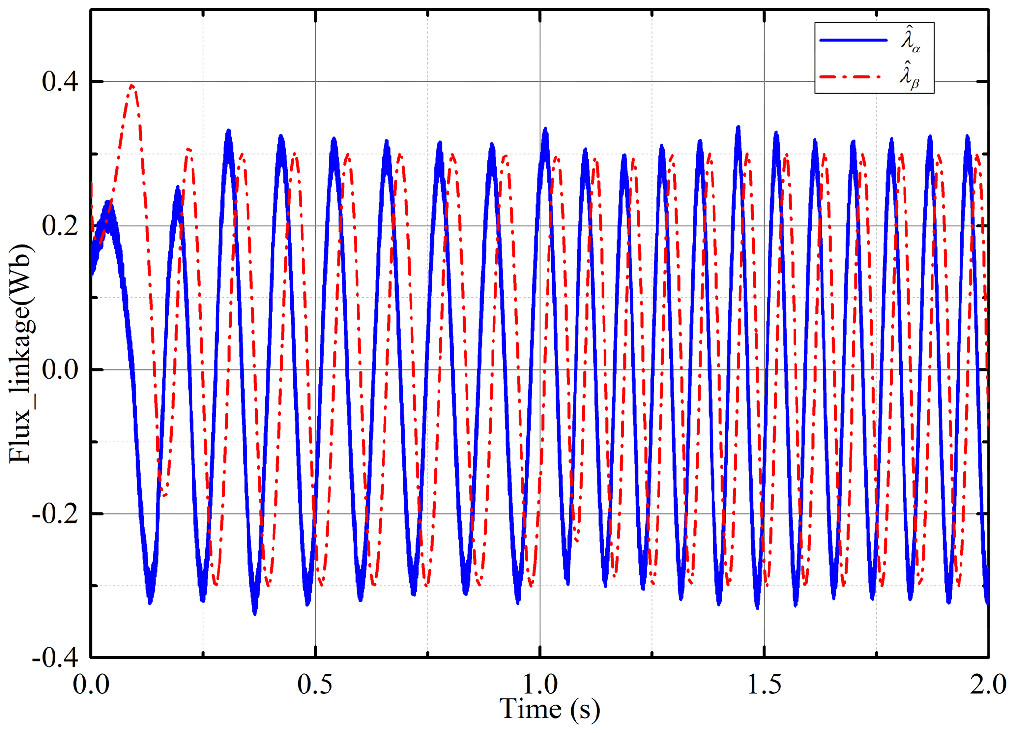
Figure 10Estimated flux linkage with the improved flux linkage observer under variable speeds.
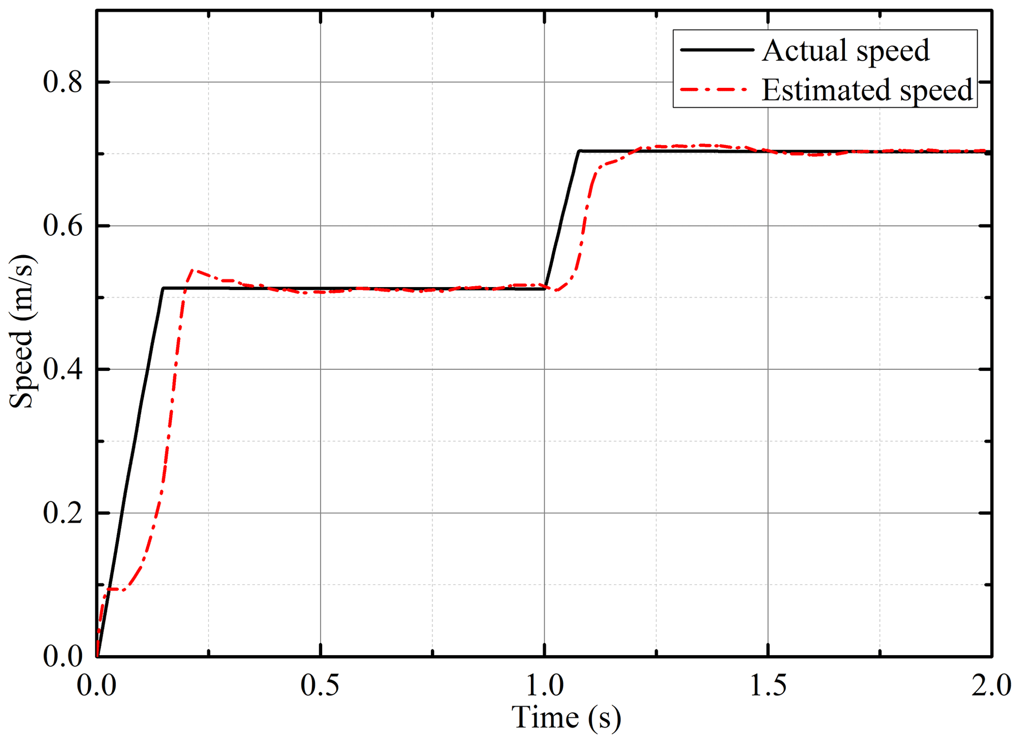
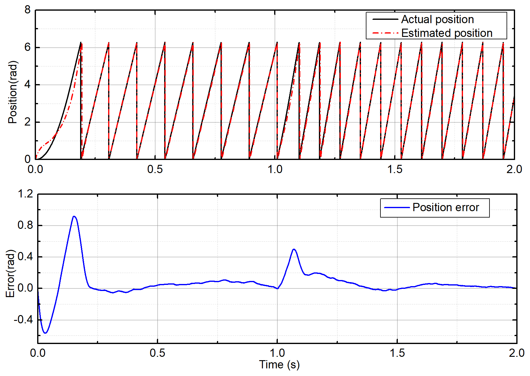
Figure 12Estimated position and error with the improved flux linkage observer under variable speeds.
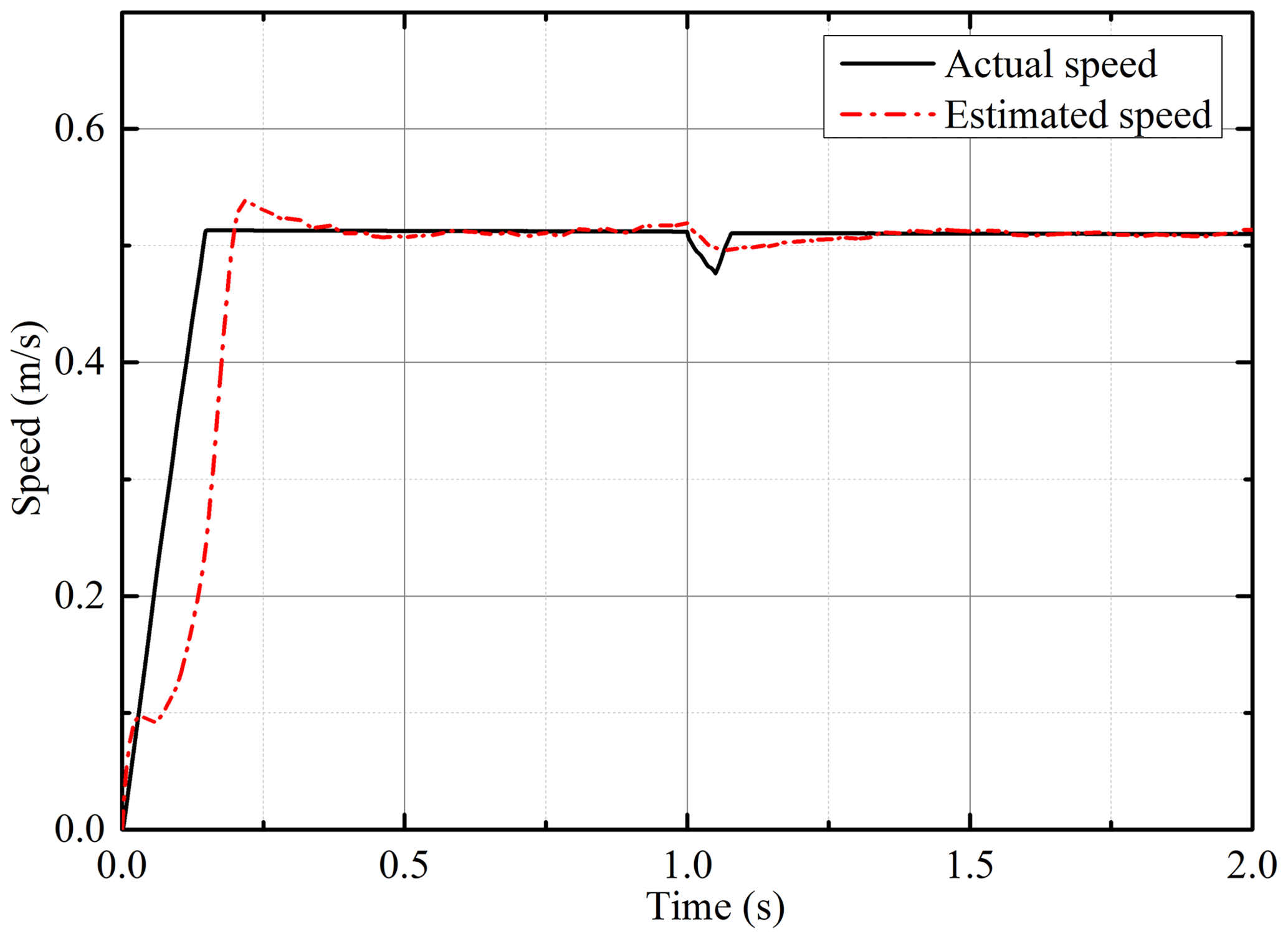
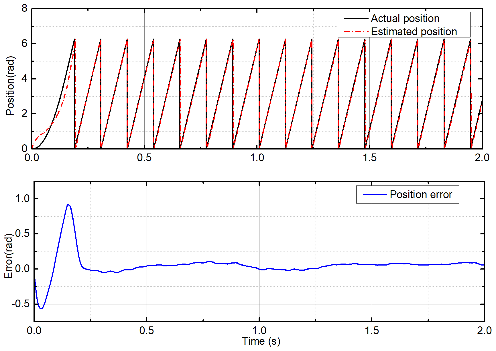
Figure 14Estimated position and error with the improved flux linkage observer under variable loads.
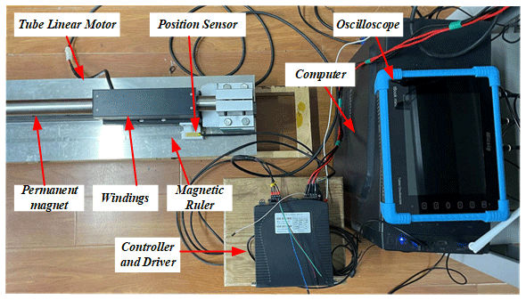
The experiment system used in this paper is shown in Fig. 15, including the tubular PMSLM, position sensor, oscilloscope, computer, controller and driver. The controller and driver are integrated together and communicate with the computer in real time. The control algorithm is set and adjusted through the computer software. The whole control system also adopts the PI control algorithm that is commonly used in practice to establish the current control loop and speed control loop. The position sensor is used to detect the position of the moving part. Commonly, the information from position sensor will feedback to the controller. However, in this paper, the information on position and speed is from the improved sensorless scheme.
The improved flux linkage observer proposed in this paper is established with the voltage and current data collected by the built-in sensor to estimate the position and speed of the PMSLM. The estimated value is compared with the actual position and speed obtained by the position sensor. Oscilloscope is used to display relevant signals for observation and debugging. Due to the limit of the length of the PMSLM and the experiment equipment, the performance of the proposed flux linkage observer can only be verified under different speeds. The overall movement time is 1 s, and the motor movement speed is changed at 0.5 s. There is an artificial deviation between the motor's actual initial position and the estimated initial position. The flux linkage, speed and position estimations of the motor are tested under the action of the improved flux linkage observer when the permanent magnet synchronous linear motor (PMSLM) is in operation.
The inaccuracy of the initial position will cause error in the calculation of the flux linkage during operation. The estimated flux linkage using the convention voltage model without a flux linkage observer is shown in Fig. 16. It can be found that the flux linkage always has a deviation and is asymmetrical. This greatly affects the performance of the estimated position and speed. Figure 17 shows the variation of the estimated flux linkage under the action of the proposed observer. Obviously, the initial error can be greatly compensated for by the improved flux linkage observer, and the estimated flux linkage converges with the actual value quickly. At 0.5 s, the controller makes the motor speed change. At the same time, the estimated flux linkage is also adjusted by the observer and soon returns to stability again. It can be found that the improved flux linkage observer has a good compensation effect on the rotor flux linkage estimation error caused by the initial-position error.
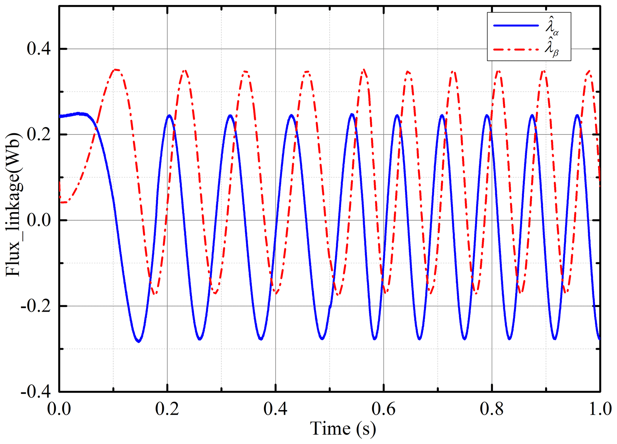
Figure 16The estimated flux linkage with the inaccurate initial-phase angle under the convention voltage model.
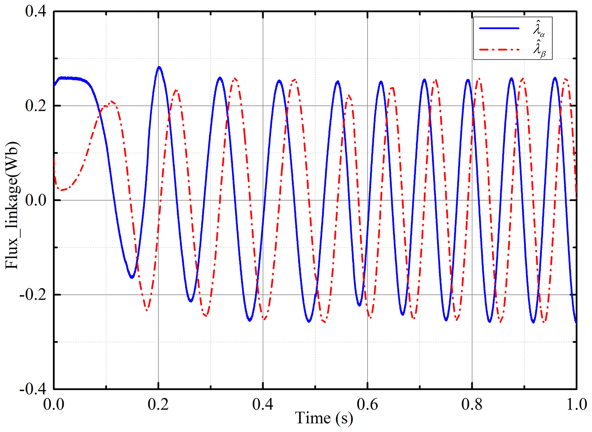
Figure 17The estimated flux linkage with the inaccurate initial-phase angle under the improved flux linkage observer.
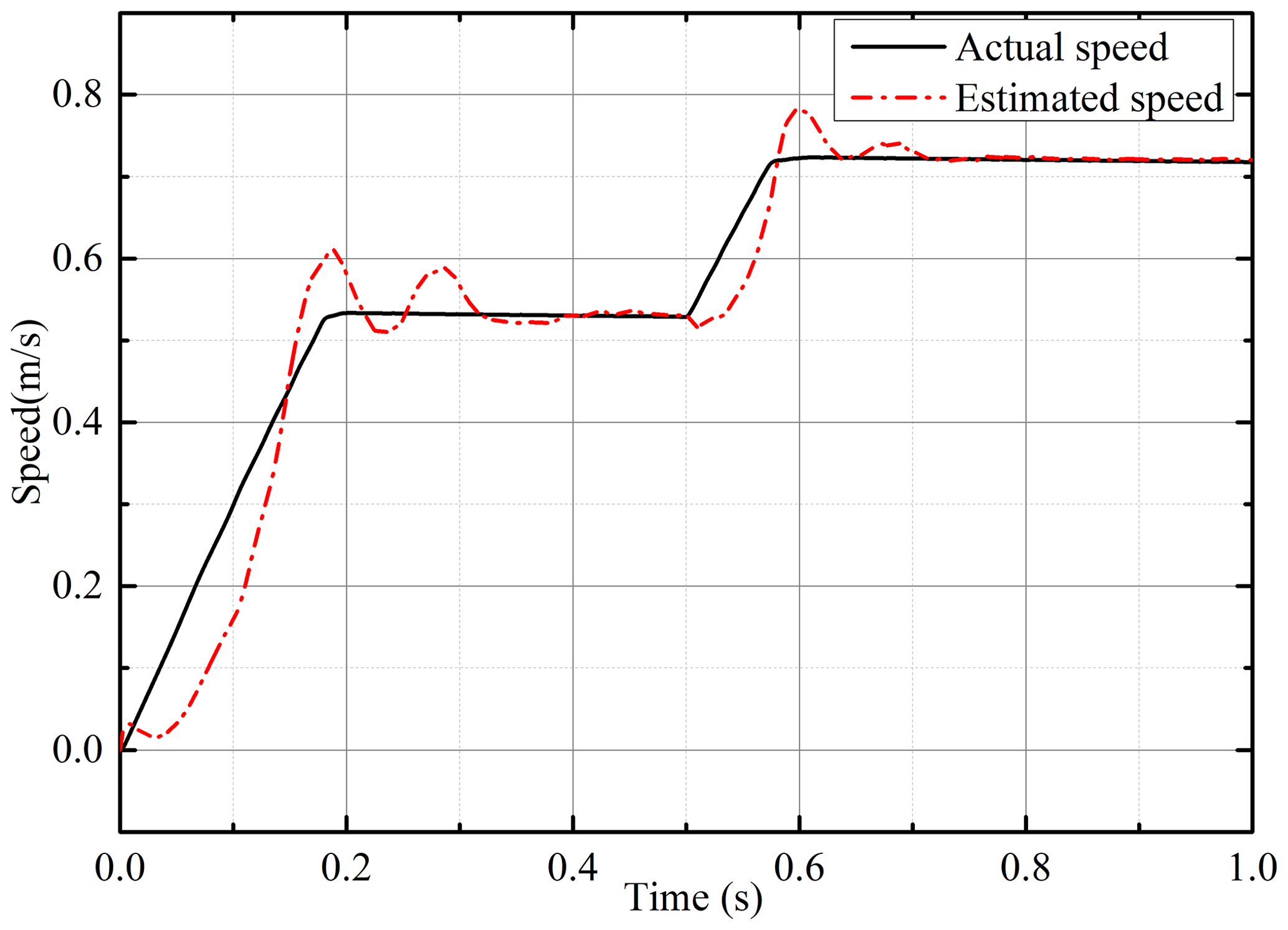
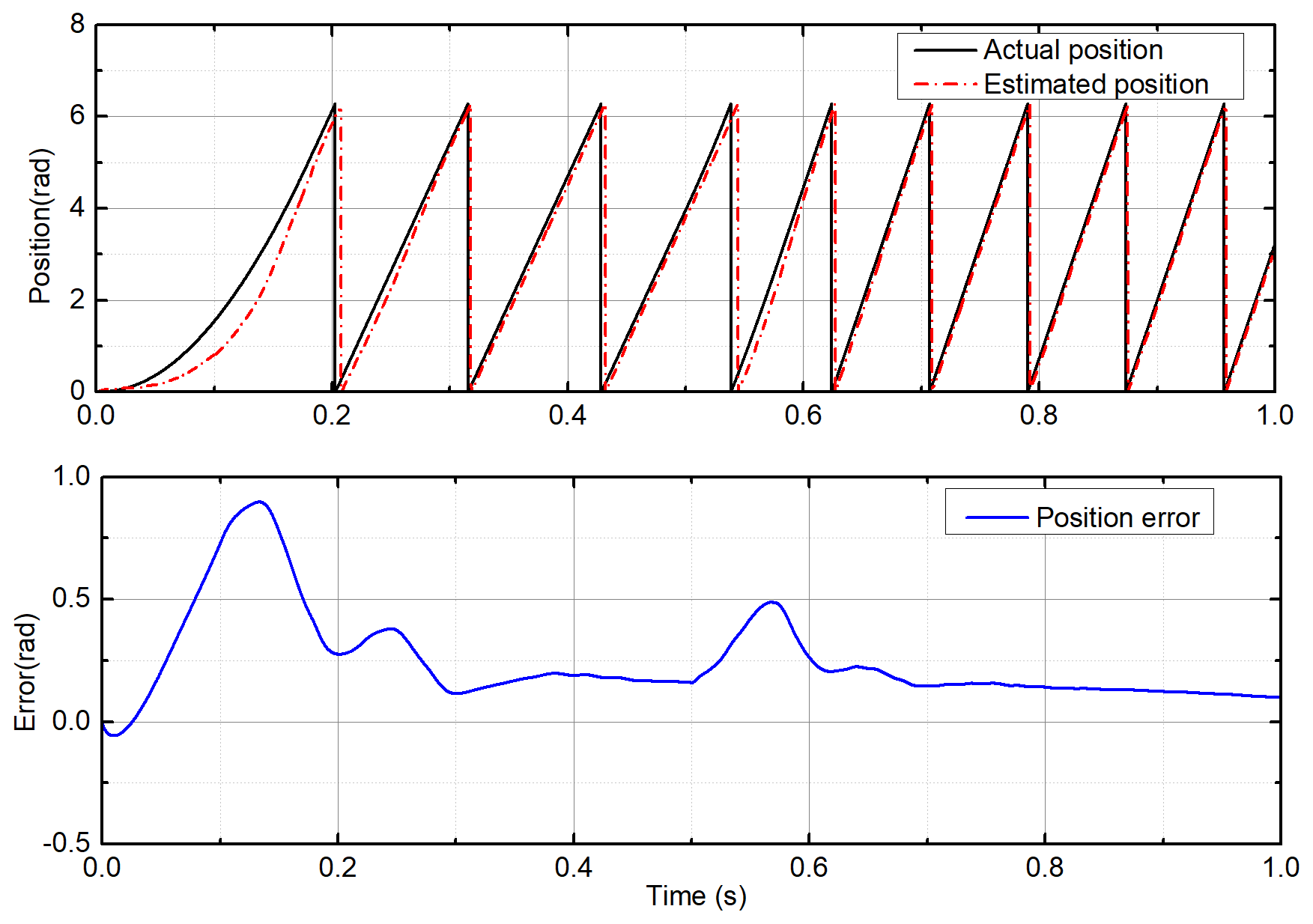
Figures 18 and 19 show the speed and position estimation of the PMSLM based on the corrected rotor flux linkage. In Fig. 18, at the beginning, the estimated speed fluctuates slightly around the actual speed. This is because the estimated flux linkage is inaccurate, and the estimated speed is stable until the initial flux linkage error is well compensated for. At 0.5 s, as the actual speed changes, the estimated speed can still track the actual speed quickly and converge to the actual speed after a short fluctuation. It can be clearly found that the speed fluctuation at 0.5 s is smaller and shorter. This shows that the proposed observer has a good performance in terms of dynamic response after the initial error is compensated for and can respond to system changes in time. The position estimation shown in Fig. 19 also has the same change. At the beginning, the estimated position is inaccurate. As the initial flux linkage error is compensated for, the estimated position constantly approaches the real position. At 0.5 s, the position error also has a small sudden change with the motor speed change, and it returns to stability again. The steady error of the estimated position is about 2 mm, and it gradually approaches the real position.
In this paper, an improved flux linkage observer of PMSLM is proposed, which can effectively suppress the speed and position estimation errors caused by the inaccurate initial position, high-frequency current noise and voltage error that may exist in practice. Firstly, the voltage model is used to calculate the stator flux linkage preliminarily, and the estimated current is calculated through the preliminary stator flux linkage using the current model. Then, a sliding-mode observer is established according to the estimated current and the actual current. The output of the observer is used as a compensation part of the voltage model to further correct the flux linkage. The theoretical model of the improved flux linkage observer is analyzed. The range of the coefficient in the observer is analyzed, and the proof of system stability is also shown in this paper. At last, the simulation and experiments show that the improved observer can greatly compensate for the estimated error and have a good dynamic response ability, especially for the initial-position error in practice. The proposed improved flux linkage observer has a simple structure and only one parameter. The common issues with regard chattering in sliding mode also have been effectively suppressed. It is suitable for practical applications.
| uα, uβ, iα, iβ | αβ-axis voltage and current |
| eα, eβ | Compensation voltage |
| Δuα, Δuβ | Voltage error |
| R | Phase resistance |
| Δiα, Δiβ | Current error |
| Ls | αβ-axis inductance |
| λα, λβ | Stator flux linkage component |
| θ | Estimated angle |
| λα0, λβ0 | Initial value of flux linkage |
| θ0 | Initial-phase angle |
| Δλα0, Δλβ0 | Initial-value error of flux linkage |
| ω | Estimated speed |
| , | Estimated stator flux linkage component |
| sα, sβ | Sliding-mode function |
| λr | Flux linkage of permanent magnets |
| k | Sliding-mode gain |
| Estimated permanent magnet flux linkage | |
| τ | Pole pitch |
| , | Estimated current |
| pn | Pole pair |
No data sets were used in this article.
WY conducted theoretical analysis and verification and wrote the manuscript. GY and LW provided experimental assistance. DL and AAZ collected the experimental results and created the figures.
The contact author has declared that none of the authors has any competing interests.
Publisher’s note: Copernicus Publications remains neutral with regard to jurisdictional claims made in the text, published maps, institutional affiliations, or any other geographical representation in this paper. While Copernicus Publications makes every effort to include appropriate place names, the final responsibility lies with the authors.
This research has been supported by the National Postdoctoral Program for Innovative Talents (grant no. BX2021126), the National Natural Science Foundation of China (grant no. 52105106), and the China Postdoctoral Science Foundation (grant no. 2021M701711).
This paper was edited by Zi Bin and reviewed by two anonymous referees.
Accetta, A., Cirrincione, M., Pucci, M., and Vitale, G.: Neural Sensorless Control of Linear Induction Motors by a Full-Order Luenberger Observer Considering the End Effects, IEEE Trans. Ind. Appl., 50, 1891–1904, https://doi.org/10.1109/TIA.2013.2288429, 2014.
Afifa, R., Ali, S., Pervaiz, M., and Lqbal, J.: Adaptive backstepping integral sliding mode control of a mimo separately excited DC motor, Robotics, 12, 105, https://doi.org/10.3390/robotics12040105, 2023.
Ahmad, S., Uppal, A., Azam, M., and Lqbal, J.: Chattering free sliding mode control and state dependent Kalman filter design for underground gasification energy conversion process, Electronics, 12, 876, https://doi.org/10.3390/electronics12040876, 2023.
Cao, R., Cheng, M., and Zhang, B.: Speed control of complementary and modular linear flux-switching permanent-magnet motor, IEEE Trans. Ind. Electron., 62, 4056–4064, https://doi.org/10.1109/TIE.2015.2390194, 2015.
Cao, R., Jiang, N., Lu, M., Zhang, Y., and Cheng, M.: Sliding mode observer based sensorless vector control of LFSPM motor for long distance drive system, IET Electr. Power App., 13, 643–651, https://doi.org/10.1049/iet-epa.2018.5505, 2019.
Cheng, M., Kong, L., Zhang, B., and Wang, Z.: Sensorless vector control of complementary and modular linear flux-switching permanent magnet motor based on MRAS and SVPWM, 2015 18th International Conference on Electrical Machines and Systems (ICEMS), 25–28 October 2015, Pattaya, Thailand, IEEE, 1597–1602, https://doi.org/10.1109/ICEMS.2015.7385296, 2015.
Cirrincione, M., Accetta, A., Pucci, M., and Vitale, G.: MRAS Speed Observer for High-Performance Linear Induction Motor Drives Based on Linear Neural Networks, IEEE Trans. Power Electron., 28, 123–134, https://doi.org/10.1109/TPEL.2012.2200506, 2013.
Cupertino, F., Giangrande, P., Salvatore, L., and Pellegrino, G.: Model based design of a sensorless control scheme for permanent magnet motors using signal injection, 2010 IEEE Energy Conversion Congress and Exposition, 12–16 September 2010, Atlanta, GA, USA, IEEE, 3139–3146, https://doi.org/10.1109/ECCE.2010.5618469, 2010.
Du, B., Zhao, T., Han, S., Song, L., and Cui, S.: Sensorless Control Strategy for IPMSM to Reduce Audible Noise by Variable Frequency Current Injection, IEEE Trans. Ind. Electron., 67, 1149–1159, https://doi.org/10.1109/TIE.2019.2898621, 2020.
Hussain, H. A. and Toliyat, H. A.: Back-EMF based sensorless vector control of tubular PM linear motors, 2015 IEEE International Electric Machines & Drives Conference (IEMDC), 10–13 May 2015, Coeur d'Alene, ID, USA, IEEE, 878–883, https://doi.org/10.1109/IEMDC.2015.7409164, 2015.
Lin, Z., Guo, H., and Xu, J.: Research on a New Sensorless Control of High Power Segmented Permanent Magnet Linear Synchronous Motor by The Improved Sliding Mode Observer, 24th International Conference on Electrical Machines and Systems (ICEMS), 31 October–3 November 2021, Gyeongju, Republic of Korea, IEEE, 862–866, https://doi.org/10.23919/ICEMS52562.2021.9634460, 2021.
Lu, H. G., Jiang, M., Li, S. W., and Liu, B. Y.: Position Sensorless Control Based on Augmented Extended Kalman Filter for Permanent Magnet Linear Synchronous Motor, Appl. Mech. Mater., 88–89, 350–354, https://doi.org/10.4028/www.scientific.net/AMM.88-89.350, 2011.
Ofori, E., Husain, T., Sozer, Y., and Husain, I.: A Pulse-Injection-Based Sensorless Position Estimation Method for a Switched Reluctance Machine Over a Wide Speed Range, IEEE Trans. Ind. Appl., 51, 3867–3876, https://doi.org/10.1109/TIA.2015.2420618, 2015.
Pasqualotto, D., Rigon, S., and Zigliotto, M.: Sensorless Speed Control of Synchronous Reluctance Motor Drives Based on Extended Kalman Filter and Neural Magnetic Model, IEEE Trans. Ind. Electron., 70, 1321–1330, https://doi.org/10.1109/TIE.2022.3159962, 2023.
Pavlitov, C., Tashev, T., Dimitrov, A., Gorbounov, Y., and Rusinov, R.: Rotor position estimation for a sensorless switched reluctance motor drive with the aid of real time adaptive filter, 2014 16th International Power Electronics and Motion Control Conference and Exposition, 21–24 September 2014, Antalya, Turkey, IEEE, 77–81, https://doi.org/10.1109/EPEPEMC.2014.6980576, 2014.
Pellegrino, G., Vagati, A., Boazzo, B., and Guglielmi, P.: Comparison of induction and PM synchronous motor drives for EV application including design examples, IEEE Trans. Ind. Appl., 48, 2322–2332, https://doi.org/10.1109/TIA.2012.2227092, 2012.
Ting, C., Chang, Y., and Chen, Y.: Backstepping direct thrust force control for sensorless PMLSM drive, IET Electr. Power App., 13, 322–331, https://doi.org/10.1049/iet-epa.2018.5269, 2019.
Wang, F. and Ge, Q.: Long Stator Linear Synchronous Motor Sensorless Control Based on Hypothetical Reference Frame, Trans. of China Electrotechnical Society, 25, 37–40, 2010.
Wang, G., Liu, R., Zhao, N., Ding, D., and Xu, D.: Enhanced Linear ADRC Strategy for HF Pulse Voltage Signal Injection-Based Sensorless IPMSM Drives, IEEE Trans. Power Electron., 34, 514–525, https://doi.org/10.1109/TPEL.2018.2814056, 2019.
Wang, L., Lu, Q., and Ye, Y.: Sensorless mover position estimation of permanent magnet linear synchronous motor, Electric Machines and Control, 16, 7–12, 2012.
Xiao, D., Ye, J., Fang, G., Xia, Z., Wang, X., and Emadi, A.: Improved Feature-Position-Based Sensorless Control Scheme for SRM Drives Based on Nonlinear State Observer at Medium and High Speeds, IEEE Trans. Power Electron., 36, 5711–5723, https://doi.org/10.1109/TPEL.2020.3030007, 2021.
Xiao, G., Tu, W., Suo, C., Tang, L., and Yang, K: Research and design of speed control for high speed sensorless brushless DC motor with commutation compensation, 2017 20th International Conference on Electrical Machines and Systems (ICEMS), 11–14 August 2017, Sydney, NSW, Australia, IEEE, 1–5, https://doi.org/10.1109/ICEMS.2017.8056026, 2017.
Yang, C., Song, B., Xie, Y., Lu, S., and Tang, X.: Stable Simultaneous Inertia and Disturbance Torque Identification for SPMSM Drive Systems Subject to Mismatched Rotor Flux Linkage, IEEE J. Em. Sel. Top. P., 10, 2445–2462, https://doi.org/10.1109/JESTPE.2021.3111122, 2022.
Zhang, T., Xu, Z., and Gerada, C.: A Nonlinear Extended State Observer for Sensorless IPMSM Drives With Optimized Gains, IEEE Trans. Ind. Appl., 56, 1485–1494, https://doi.org/10.1109/TIA.2019.2959537, 2020.
Zhang, X., Hou, B., and Yang M.: Deadbeat predictive current control of permanent-magnet synchronous motors with stator current and disturbance observer, IEEE Trans. Power Electron., 32, 3818–3834, https://doi.org/10.1109/TPEL.2016.2592534, 2016.
Zhang, Y., Yin, Z., Bai, C., Wang, G., and Liu, J.: A Rotor Position and Speed Estimation Method Using an Improved Linear Extended State Observer for IPMSM Sensorless Drives, IEEE Trans. Power Electron., 36, 14062–14073, https://doi.org/10.1109/TPEL.2021.3085126, 2021.
Zhao, W., Yang, A., Ji, J., Chen, Q., and Zhu, J.: Modified Flux Linkage Observer for Sensorless Direct Thrust Force Control of Linear Vernier Permanent Magnet Motor, IEEE Trans. Power Electron., 34, 7800–7811, https://doi.org/10.1109/TPEL.2018.2879411, 2019.